WO2022085079A1 - 回転子、電動機、圧縮機および冷凍サイクル装置 - Google Patents
回転子、電動機、圧縮機および冷凍サイクル装置 Download PDFInfo
- Publication number
- WO2022085079A1 WO2022085079A1 PCT/JP2020/039412 JP2020039412W WO2022085079A1 WO 2022085079 A1 WO2022085079 A1 WO 2022085079A1 JP 2020039412 W JP2020039412 W JP 2020039412W WO 2022085079 A1 WO2022085079 A1 WO 2022085079A1
- Authority
- WO
- WIPO (PCT)
- Prior art keywords
- permanent magnet
- rotor
- axis
- magnetic pole
- rotor core
- Prior art date
- Legal status (The legal status is an assumption and is not a legal conclusion. Google has not performed a legal analysis and makes no representation as to the accuracy of the status listed.)
- Ceased
Links
Images











Classifications
-
- H—ELECTRICITY
- H02—GENERATION; CONVERSION OR DISTRIBUTION OF ELECTRIC POWER
- H02K—DYNAMO-ELECTRIC MACHINES
- H02K1/00—Details of the magnetic circuit
- H02K1/06—Details of the magnetic circuit characterised by the shape, form or construction
- H02K1/22—Rotating parts of the magnetic circuit
-
- H—ELECTRICITY
- H02—GENERATION; CONVERSION OR DISTRIBUTION OF ELECTRIC POWER
- H02K—DYNAMO-ELECTRIC MACHINES
- H02K1/00—Details of the magnetic circuit
- H02K1/06—Details of the magnetic circuit characterised by the shape, form or construction
- H02K1/22—Rotating parts of the magnetic circuit
- H02K1/27—Rotor cores with permanent magnets
-
- H—ELECTRICITY
- H02—GENERATION; CONVERSION OR DISTRIBUTION OF ELECTRIC POWER
- H02K—DYNAMO-ELECTRIC MACHINES
- H02K7/00—Arrangements for handling mechanical energy structurally associated with dynamo-electric machines, e.g. structural association with mechanical driving motors or auxiliary dynamo-electric machines
- H02K7/14—Structural association with mechanical loads, e.g. with hand-held machine tools or fans
Definitions
- This disclosure relates to rotors, motors, compressors and refrigeration cycle devices.
- the rotor In the compressor motor, the rotor is fixed to the shaft connected to the compression mechanism.
- the compression mechanism portion has a rotating portion eccentric with respect to the central axis of the shaft in order to compress the refrigerant. Therefore, a centrifugal force acts on the motor due to the compression operation by the compression mechanism.
- the rotor is provided with a balance weight for canceling the above centrifugal force. Further, in addition to the balance weight, an electric motor in which the air gap between the rotor and the stator is made non-uniform in the circumferential direction has also been proposed (see, for example, Patent Document 1).
- the balance weight is composed of a non-magnetic material such as brass, which has a large specific gravity. In order to reduce the manufacturing cost of the motor, it is desirable to reduce the size of the balance weight.
- the present disclosure has been made in order to solve the above-mentioned problems, and an object thereof is to reduce the size of the balance weight portion of the rotor.
- the rotor in the present disclosure is provided in the compressor.
- the rotor has an annular rotor core about the axis.
- a first permanent magnet constituting the first magnetic pole is arranged on the rotor core.
- a second permanent magnet constituting a second magnetic pole is arranged adjacent to the first permanent magnet in the circumferential direction about the axis.
- a balance weight portion is attached to the end portion of the rotor core in the direction of the axis.
- the residual magnetic flux density of the second permanent magnet is lower than the residual magnetic flux density of the first permanent magnet.
- At least a part of the first magnetic pole is located at a position facing the balance weight portion in the direction of the axis.
- a magnetic attraction force is generated by the difference in magnetic flux density between the first magnetic pole and the second magnetic pole of the rotor, and the centrifugal force generated by the balance weight portion can be supplemented. This makes it possible to reduce the size of the balance weight portion.
- FIG. 1 It is sectional drawing which shows the electric motor of Embodiment 1.
- FIG. 2 is sectional drawing which shows the rotor of Embodiment 1.
- FIG. It is a vertical sectional view which shows the rotor of Embodiment 1.
- FIG. It is a perspective view which shows the rotor of Embodiment 1.
- FIG. It is a figure for demonstrating the positional relationship between the permanent magnet of the rotor of Embodiment 1 and a balance weight.
- FIG. It is a schematic diagram which shows the cylinder part of the compressor of Embodiment 1.
- FIG. It is a schematic diagram (A)-(D) which shows the operation of the cylinder part of the compressor of Embodiment 1.
- FIG. It is a graph which shows the hysteresis curve of a permanent magnet. It is sectional drawing which shows the other structural example of the rotor of Embodiment 1.
- FIG. It is a cross-sectional view which shows the rotor of Embodiment 2. It is sectional drawing which shows the other structural example of the rotor of Embodiment 2. It is a vertical sectional view which shows the rotor of Embodiment 3.
- FIG. It is sectional drawing which shows the other structural example of the rotor of Embodiment 3.
- FIG. It is a cross-sectional view which shows the rotor of Embodiment 4. It is sectional drawing which shows the other structural example of the rotor of Embodiment 4.
- FIG. 1 is a cross-sectional view showing the electric motor 100 of the first embodiment.
- the electric motor 100 is a synchronous motor, and is incorporated in the compressor 7 (FIG. 6) to drive the compression mechanism unit 6.
- the electric motor 100 has a rotor 1 that can rotate around the axis Ax, and a stator 5 that surrounds the rotor 1.
- An air gap of, for example, 0.3 to 1.0 mm is formed between the rotor 1 and the stator 5.
- the direction of the axis Ax that defines the rotation center of the rotor 1 is referred to as the "axial direction”.
- the radial direction centered on the axis Ax is defined as the "diameter direction”.
- the circumferential direction centered on the axis Ax is defined as the "circumferential direction", and is indicated by an arrow R in FIG. 1 and the like.
- a cross-sectional view on a plane parallel to the axis Ax is a vertical cross-sectional view
- a cross-sectional view on a plane orthogonal to the axis Ax is a cross-sectional view.
- the stator 5 has a stator core 50 and a coil 55 wound around the stator core 50.
- the stator core 50 is composed of a laminated body in which a plurality of electromagnetic steel sheets are laminated in the axial direction and fixed by caulking or the like.
- the plate thickness of the electromagnetic steel sheet is, for example, 0.1 to 0.7 mm.
- the stator core 50 has an annular yoke portion 51 centered on the axis Ax, and a plurality of teeth 52 extending radially inward from the yoke portion 51.
- the teeth 52 are arranged at equal intervals in the circumferential direction.
- the number of teeth 52 is 18 here. However, the number of teeth 52 is not limited to 18, and may be 2 or more.
- a slot 53 which is a space for accommodating the coil 55, is formed between the teeth 52 adjacent to each other in the circumferential direction.
- the number of slots 53 is the same as the number of teeth 52.
- the coil 55 is composed of a magnet wire and is wound around the teeth 52 by a centralized winding or a distributed winding.
- the coil 55 has three-phase winding portions of U phase, V phase and W phase, and these winding portions are connected by Y connection or delta connection.
- an insulating portion made of resin is provided between the stator core 50 and the coil 55.
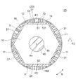
- FIG. 2 is a cross-sectional view showing the rotor 1 of the first embodiment.
- the rotor 1 has a cylindrical rotor core 10 and a permanent magnet 20 attached to the rotor core 10.
- the rotor core 10 is composed of a laminated body in which a plurality of electromagnetic steel sheets are laminated in the axial direction and fixed by caulking or the like.
- the plate thickness of the electromagnetic steel sheet is, for example, 0.1 to 0.7 mm.
- the rotor core 10 has an inner circumference 15 and an outer circumference 16. Both the inner circumference 15 and the outer circumference 16 are circular with the axis Ax as the center.
- a shaft 40 is fixed to the inner circumference 15 of the rotor core 10 by shrink fitting, press fitting, adhesion, or the like.
- the central axis of the shaft 40 is the axis line Ax described above.
- a plurality of magnet insertion holes 11 are formed along the outer circumference 16 of the rotor core 10.
- the magnet insertion hole 11 has a rectangular cross-sectional shape in a plane orthogonal to the axial direction.
- the magnet insertion hole 11 extends in a direction orthogonal to a radial straight line passing through the center in the longitudinal direction.
- the six magnet insertion holes 11 have the same circumferential width and the same radial thickness, and penetrate the rotor core 10 in the axial direction.
- the number of magnet insertion holes 11 is not limited to 6.
- One permanent magnet 20 is inserted into each magnet insertion hole 11 of the rotor core 10. In other words, six permanent magnets 20 are embedded in the rotor core 10. One permanent magnet 20 constitutes one magnetic pole, and the number of poles of the rotor 1 is 6. However, the number of poles of the rotor 1 is not limited to 6, and may be 2 or more.
- These permanent magnets 20 are arranged so that the polarities of the magnetic pole surfaces on the outer peripheral side of the adjacent permanent magnets 20 are opposite to each other. That is, when the magnetic pole surface on the outer peripheral side of a certain permanent magnet 20 is N pole, the magnetic pole surface on the outer peripheral side of the adjacent permanent magnet 20 is S pole.
- the six permanent magnets 20 include five first permanent magnets 21 and one second permanent magnet 22.
- the magnetic pole composed of the first permanent magnet 21 is referred to as the first magnetic pole P1.
- the magnetic pole configured by the second permanent magnet 22 is referred to as a second magnetic pole P2.
- the first permanent magnet 21 and the second permanent magnet 22 have the same circumferential width, the same radial thickness, and the same axial length. That is, the first permanent magnet 21 and the second permanent magnet 22 have the same shape.
- Both the first permanent magnet 21 and the second permanent magnet 22 are composed of a rare earth magnet, more specifically a rare earth sintered magnet. However, the composition of the first permanent magnet 21 and the second permanent magnet 22 are different, and therefore the residual magnetic flux density is different.
- the residual magnetic flux density of the second permanent magnet 22 is lower than the residual magnetic flux density of the first permanent magnet 21. That is, the magnetic force of the second permanent magnet 22 is smaller than the magnetic force of the first permanent magnet 21. Due to the difference in the residual magnetic flux density between the first permanent magnet 21 and the second permanent magnet 22, a magnetic attraction force that supplements the centrifugal force of the balance weight portion is generated, as will be described later.
- Flux barriers 12 are formed on both sides of the rotor core 10 in the circumferential direction of each magnet insertion hole 11.
- a thin wall portion is formed between the flux barrier 12 and the outer peripheral portion 16 of the rotor core 10. The thin portion is formed to have the same width as the thickness of the magnetic steel sheet in order to suppress the short-circuit magnetic flux between adjacent magnetic poles.
- a slit 13 is formed in the region between each magnet insertion hole 11 and the outer peripheral region 16 in the rotor core 10, that is, in the outer peripheral region.
- the slit 13 is formed to smooth the magnetic flux density distribution on the surface of the rotor 1.
- the eight slits 13 are arranged symmetrically with respect to the circumferential center, that is, the polar center of each magnet insertion hole 11.
- the number and arrangement of the slits 13 are arbitrary.
- the magnet insertion hole 11 into which the first permanent magnet 21 is inserted is referred to as a "first magnet insertion hole”
- the magnet insertion hole 11 into which the second permanent magnet 22 is inserted is referred to as a "second magnet insertion hole”.
- each magnet insertion hole 11 may be inserted in each magnet insertion hole 11.
- one magnetic pole is formed by two or more permanent magnets 20 inserted into one magnet insertion hole 11.
- each magnet insertion hole 11 may extend in a V shape that is convex toward the inner peripheral side.
- FIG. 3 is a vertical sectional view showing the rotor 1.
- FIG. 4 is a perspective view showing the rotor 1.
- a balance weight 31 is attached to one end of the rotor core 10 in the axial direction.
- a balance weight 32 is attached to the other end of the rotor core 10 in the axial direction.
- the balance weights 31 and 32 are both made of brass, for example.
- the balance weights 31 and 32 are fixed to the rotor core 10 by, for example, rivets or the like.
- the balance weight 31 has a disk-shaped end plate portion 31b centered on the axis Ax, and a balance weight portion 31a formed in a part of the end plate portion 31b in the circumferential direction.
- the balance weight portion 31a is formed, for example, in a semicircular ring centered on the axis Ax.
- the balance weight 32 has a disk-shaped end plate portion 32b centered on the axis Ax, and a balance weight portion 32a formed in a part of the end plate portion 32b in the circumferential direction.
- the balance weight portion 32a is formed, for example, in a semicircular ring centered on the axis Ax.
- the balance weight portion 31a and the end plate portion 31b are integrally formed, but they may be separate bodies.
- the balance weight portion 32a and the end plate portion 32b are integrally formed here, they may be separate bodies.
- the two balance weight portions 31a and 32a are positioned symmetrically with respect to the axis Ax.
- the weights of the balance weight portions 31a and 32a are determined according to the centrifugal force generated by the compression mechanism portion 6 (FIG. 6) described later.
- FIG. 5 is a schematic diagram showing the positional relationship between the permanent magnets 21 and 22 of the rotor 1 and the balance weight portion 31a.
- a part of the first permanent magnet 21, that is, a part of the first magnetic pole P1 is located at a position facing the balance weight portion 31a in the axial direction.
- the second permanent magnet 22, that is, the second magnetic pole P2 is on the side opposite to the balance weight portion 31a with respect to the axis Ax.
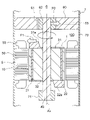
- FIG. 6 is a schematic diagram showing a basic configuration of a compressor 7 provided with an electric motor 100.
- the compressor 7 may be a rotary compressor or a scroll compressor.
- the compressor 7 includes a compression mechanism unit 6, an electric motor 100 that drives the compression mechanism unit 6, a shaft 40 that connects the compression mechanism unit 6 and the electric motor 100, a bearing 71 that rotatably supports the shaft 40, and these. It is provided with a closed container 70 for accommodating the above.
- the axial direction of the shaft 40 is the vertical direction, and the motor 100 is arranged below the compression mechanism portion 6.
- the electric motor 100 may be arranged above the compression mechanism unit 6.
- the closed container 70 is a container made of a steel plate. Inside the closed container 70, the stator 5 of the electric motor 100 is incorporated by shrink fitting, press fitting, welding, or the like.
- the bearing 71 is arranged on the side opposite to the compression mechanism portion 6 with the motor 100 interposed therebetween.
- the compression mechanism portion 6 includes a cylinder 60 having a cylinder chamber 61, a rolling piston 62 as a rotating portion fixed to the shaft 40, and a vane 63 (FIG. 7) that divides the inside of the cylinder chamber 61 into a suction side and a compression side.
- a vane 63 FIG. 7
- the cylinder chamber 61 has a circular cross section centered on the axis Ax, and a rolling piston 62 attached to the shaft 40 is located inside the cylinder chamber 61.
- the rolling piston 62 has a cylindrical shape, and its center is eccentric with respect to the axis Ax. When the shaft 40 rotates, the rolling piston 62 rotates eccentrically in the cylinder chamber 61.
- the cylinder 60 is formed with a vane groove 64 into which the vane 63 is inserted.
- One end of the vane groove 64 communicates with the cylinder chamber 61, and the other end of the vane groove 64 communicates with the back pressure chamber.
- the vane 63 is provided so as to be reciprocating in the vane groove 64.
- the vane 63 is pushed out from the vane groove 64 into the cylinder chamber 61 by a spring and is in contact with the outer peripheral surface of the rolling piston 62.
- the cylinder 60 is formed with a suction port 65 for sucking refrigerant gas from the outside of the closed container 70 into the cylinder chamber 61.
- the suction port 65 is connected to the accumulator by, for example, a suction tube.
- the cylinder 60 is also provided with a discharge port (not shown).
- a discharge port (not shown).
- the discharge valve provided in the discharge port opens, and the refrigerant gas is discharged from the cylinder chamber 61 into the closed container 70.
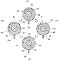
- FIGS. 8 (A) to 8 (D) are schematic views showing the compression operation of the refrigerant in the cylinder 60 due to the rotation of the shaft 40.
- the vane 63 divides the space formed by the inner peripheral surface of the cylinder chamber 61 and the outer peripheral surface of the rolling piston 62 into two operating chambers.
- the operating chamber communicating with the suction port 65 functions as a suction chamber for sucking the low-pressure refrigerant gas
- the other operating chamber functions as a compression chamber for compressing the refrigerant.
- the rolling piston 62 rotates eccentrically in the cylinder chamber 61, so that the refrigerant gas is sucked into the cylinder chamber 61 from the suction port 65 (FIG. 7), and the cylinder chamber 61 is sucked. It is compressed within 61. The refrigerant gas compressed in the cylinder chamber 61 is discharged into the closed container 70 from the discharge port.
- the balance weight portion 31a on the compression mechanism portion 6 side is arranged on the side opposite to the eccentric shaft of the rolling piston 62 with respect to the axis Ax, and the balance weight portion 32a on the bearing 71 side is arranged on the eccentric shaft of the rolling piston 62. It is placed on the same side as. Further, the weight of the balance weight portion 31a is set to be heavier than the weight of the balance weight portion 32a.
- the centrifugal force generated in the balance weight portion 31a is defined as the centrifugal force F1.
- the first permanent magnet 21 and the second permanent magnet 22 of the rotor 1 have the same shape.
- the residual magnetic flux density of the second permanent magnet 22 is lower than the residual magnetic flux density of the first permanent magnet 21.
- the residual magnetic flux density (Br) of a permanent magnet indicates the magnitude of the magnetic flux that can be generated by a permanent magnet.
- FIG. 9 is a diagram showing the relationship between the magnetic flux density and the magnetic field of a general permanent magnet. In FIG. 9, the intersection of the hysteresis curve (BH) and the vertical axis represents the residual magnetic flux density Br.
- the magnetic flux density Bg at the air gap can be obtained by the following equation (1).
- Bg 1 / (1 + Pc ⁇ ⁇ rec) ⁇ Br ... (1)
- the ⁇ rec of the equation (1) is the recoil magnetic permeability which is the slope of the hysteresis curve.
- the recoil magnetic permeability ⁇ rec is generally a numerical value of 1 to 1.2, and the difference due to the difference in the material of the permanent magnet is small.
- the magnetic flux density Bg at the air gap is proportional to the residual magnetic flux density Br if the shape of the permanent magnet does not change. That is, by using permanent magnets having different residual magnetic flux densities Br, the magnetic flux densities in the air gap, that is, the magnetic flux densities on the surface of the rotor can be changed.
- the residual magnetic flux density of the second permanent magnet 22 is lower than the residual magnetic flux density of the first permanent magnet 21. Therefore, as shown in FIG. 5, the magnetic flux density on the surface of the rotor 1 is low on the second magnetic pole P2 side (lower side in the figure) and higher on the first magnetic pole P1 side (upper side in the figure).
- the force attracted by the rotor 1 and the stator 5 is small on the second magnetic pole P2 side (lower side in the figure) and larger on the first magnetic pole P1 side (upper side in the figure). Therefore, when looking at the rotor 1 as a whole, a magnetic attraction force F2 is generated in the direction from the second magnetic pole P2 toward the first magnetic pole P1.
- a part of the first permanent magnet 21, that is, a part of the first magnetic pole P1 is located at a position facing the balance weight portion 31a in the axial direction as shown by an arrow A1 in FIG.
- the second permanent magnet 22, that is, the second magnetic pole P2 is on the side opposite to the balance weight portion 31a with respect to the axis Ax.
- the magnetic attraction force F2 is generated in the same direction as the centrifugal force F1 (FIG. 6) generated by the balance weight portion 31a. Can be done. As a result, the centrifugal force F1 generated by the balance weight portion 31a can be reduced, and the balance weight portion 31a can be miniaturized.
- the amount of brass and the like constituting the balance weight portion 31a can be reduced, and the manufacturing cost of the motor 100 can be reduced.
- first permanent magnet 21 and the second permanent magnet 22 have the same shape, all the six magnet insertion holes 11 of the rotor core 10 can be formed into the same shape. Therefore, as the rotor core 10, a rotor core having a general configuration can be used.
- the rotor 1 has two balance weight portions 31a and 32a, but the first permanent magnet 21, that is, the first magnetic pole P1 faces the balance weight portion to be miniaturized in the axial direction. It may be arranged as follows. Further, the second permanent magnet 22, that is, the second magnetic pole P2 may be arranged on the side opposite to the balance weight portion which is desired to be miniaturized with respect to the axis Ax.
- the number of the second magnetic poles P2 of the rotor 1 was one.
- the rotor 1 may be provided with two or more second magnetic poles P2 adjacent to each other. In this case, it is desirable that the number of the second magnetic poles P2 is an even number.
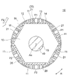
- FIG. 10 shows a configuration example of a rotor 1 having two second magnetic poles P2, that is, two second permanent magnets 22.
- the number of the first magnetic poles P1 is four, and the number of the second magnetic poles P2 is two.
- the number of the second magnetic poles P2 is an even number, the imbalance of the magnetic flux flow in the rotor core 10 can be reduced, the magnetic flux leakage to the shaft 40 can be suppressed, and the permanent magnet 20 can be suppressed. It becomes possible to effectively utilize the magnetic flux of.
- the number of the second magnetic poles P2 increases with respect to the number of the first magnetic poles P1
- the magnetic flux interlinking the coil 55 of the stator 5 decreases. Therefore, it is desirable that the number of the second magnetic poles P2 is smaller than the number of the first magnetic poles.
- first permanent magnet 21 and the second permanent magnet 22 are both rare earth magnets here, but the present invention is not limited thereto.
- the first permanent magnet 21 may be a rare earth magnet and the second permanent magnet 22 may be a ferrite magnet. This point will be described in the sixth embodiment.
- a part of the first magnetic pole P1 that is, three of the five first magnetic poles P1 face the balance weight portion 31a in the axial direction, but the first magnetic pole All of P1 may face the balance weight portion 31a in the axial direction. That is, at least a part of the first magnetic pole P1 may face the balance weight portion 31a in the axial direction.
- the rotor 1 of the first embodiment has a first permanent magnet 21 constituting the first magnetic pole P1 and a second permanent magnet 22 constituting the second magnetic pole P2.
- the residual magnetic flux density of the second permanent magnet 22 is lower than the residual magnetic flux density of the first permanent magnet 21.
- At least a part of the first magnetic pole P1 is located at a position facing the balance weight portion 31a in the axial direction.
- the balance weight portion 31a can be miniaturized, and the manufacturing cost of the electric motor 100 can be reduced.
- first permanent magnet 21 and the second permanent magnet 22 have the same shape, all the magnet insertion holes 11 of the rotor core 10 can have the same shape. That is, as the rotor core 10, a rotor core having a general configuration can be used, and the manufacturing cost can be further reduced.
- the number of the second permanent magnets 22 is set to an even number, the imbalance of the magnetic flux flow in the rotor core 10 is reduced, the magnetic flux leakage to the shaft 40 is suppressed, and the magnetic flux of the permanent magnet 20 is reduced. It can be used effectively.
- the balance weight portion 31a is located in the direction opposite to the eccentric direction of the rolling piston 62 of the compression mechanism portion 6 (that is, the direction of the centrifugal force F0 shown in FIG. 6) with respect to the axis Ax, the compression mechanism portion The centrifugal force applied to the shaft 40 during the operation of 6 can be effectively offset.
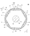
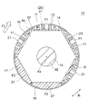
- FIG. 11 is a cross-sectional view showing the rotor 1A of the second embodiment.
- the rotor core 10 of the rotor 1A has six magnet insertion holes 11, and a permanent magnet 20 is inserted into each magnet insertion hole 11. That is, the rotor 1A has six permanent magnets 20 and has six poles. However, the number of poles is not limited to 6.
- the six permanent magnets 20 include five first permanent magnets 21 and one second permanent magnet 23.
- the magnetic pole composed of the first permanent magnet 21 is referred to as the first magnetic pole P1.
- the magnetic pole configured by the second permanent magnet 23 is referred to as a second magnetic pole P2.
- the first permanent magnet 21 and the second permanent magnet 23 are made of the same material. Therefore, the first permanent magnet 21 and the second permanent magnet 23 have the same residual magnetic flux density as each other.
- the first permanent magnet 21 has a width W1 in the circumferential direction
- the second permanent magnet 23 has a width W2 in the circumferential direction.
- the width W2 of the second permanent magnet 23 is narrower than the width W1 of the first permanent magnet 21 (W1> W2).
- the first permanent magnet 21 and the second permanent magnet 23 have the same radial thickness and the same axial length.
- the width W2 of the second permanent magnet 23 is narrower than the width W1 of the first permanent magnet 21, the amount of magnetic flux emitted from the second permanent magnet 23 is smaller than the amount of magnetic flux emitted from the first permanent magnet 21. Therefore, the magnetic flux density on the surface of the rotor 1A is low on the second magnetic pole P2 side (lower side in the figure) and higher on the first magnetic pole P1 side (upper side in the figure).
- the attractive force attracted by the rotor 1A and the stator 5 is small on the second magnetic pole P2 side (lower side in the figure) and larger on the first magnetic pole P1 side (upper side in the figure).
- a magnetic attraction force F2 is generated in the direction from the second magnetic pole P2 toward the first magnetic pole P1.
- a part of the first permanent magnet 21, that is, a part of the first magnetic pole P1 is located at a position facing the balance weight portion 31a in the axial direction.
- the second permanent magnet 23, that is, the second magnetic pole P2 is on the opposite side of the axis Ax from the balance weight portion 31a.
- a magnetic attraction force F2 is generated in the same direction as the centrifugal force F1 generated by the balance weight portion 31a. do.
- the centrifugal force F1 by the balance weight portion 31a can be reduced, and the balance weight portion 31a can be miniaturized.
- the rotor 1A may be provided with two or more second magnetic poles P2 adjacent to each other. In this case, it is desirable that the number of the second magnetic poles P2, that is, the number of the second permanent magnets 23 is an even number.
- FIG. 12 shows a configuration example of a rotor 1A having two second magnetic poles P2, that is, two second permanent magnets 23.
- the number of the second magnetic poles P2 is an even number, as described in the first embodiment, the imbalance of the magnetic flux flow in the rotor core 10 is reduced, and the magnetic flux leakage to the shaft 40 is suppressed. This makes it possible to effectively use the magnetic flux of the permanent magnet 20.
- the rotor 1A of the second embodiment is configured in the same manner as the rotor 1 of the first embodiment.
- the circumferential width W2 of the second permanent magnet 23 is narrower than the circumferential width W1 of the first permanent magnet 21, and the first magnetic pole P1 Is located at a position facing the balance weight portion 31a in the axial direction. Therefore, due to the difference in magnetic flux density between the first magnetic pole P1 side and the second magnetic pole P2 side on the surface of the rotor 1A, a magnetic attraction force F2 is generated in the same direction as the centrifugal force F1 by the balance weight portion 31a. As a result, the balance weight portion 31a can be miniaturized and the manufacturing cost of the electric motor 100 can be reduced.
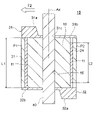
- FIG. 13 is a vertical sectional view showing the rotor 1B of the third embodiment.
- the rotor core 10 of the rotor 1B has six magnet insertion holes 11, and a permanent magnet 20 is inserted into each magnet insertion hole 11. That is, the rotor 1B has six permanent magnets 20 and has six poles. However, the number of poles is not limited to 6.
- the six permanent magnets 20 include five first permanent magnets 21 and one second permanent magnet 24.
- the magnetic pole composed of the first permanent magnet 21 is referred to as the first magnetic pole P1.
- the magnetic pole configured by the second permanent magnet 24 is referred to as a second magnetic pole P2.
- the first permanent magnet 21 and the second permanent magnet 24 are made of the same material. Therefore, the first permanent magnet 21 and the second permanent magnet 24 have the same residual magnetic flux density as each other.
- the first permanent magnet 21 has a length L1 in the axial direction
- the second permanent magnet 24 has a length L2 in the axial direction.
- the length L2 of the second permanent magnet 24 is shorter than the length L1 of the first permanent magnet 21 (L1> L2).
- the first permanent magnet 21 and the second permanent magnet 24 have the same circumferential width and the same radial thickness.
- the amount of magnetic flux emitted from the second permanent magnet 24 is smaller than the amount of magnetic flux emitted from the first permanent magnet 21. .. Therefore, the magnetic flux density on the surface of the rotor 1B is low on the second magnetic pole P2 side (right side in the figure) and high on the first magnetic pole P1 side (left side in the figure).
- a part of the first permanent magnet 21, that is, a part of the first magnetic pole P1 is located at a position facing the balance weight portion 31a in the axial direction.
- the second permanent magnet 24, that is, the second magnetic pole P2 is on the side opposite to the balance weight portion 31a with respect to the axis Ax.
- a magnetic attraction force F2 is generated in the same direction as the centrifugal force F1 generated by the balance weight portion 31a. do.
- the centrifugal force F1 by the balance weight portion 31a can be reduced, and the balance weight portion 31a can be miniaturized.
- the rotor 1B may be provided with two or more second magnetic poles P2 adjacent to each other. In this case, it is desirable that the number of the second magnetic poles P2, that is, the number of the second permanent magnets 24 is an even number.
- FIG. 14 shows a configuration example of a rotor 1B having two second magnetic poles P2, that is, two second permanent magnets 24.
- the number of the second magnetic poles P2 is an even number, as described in the first embodiment, the imbalance of the magnetic flux flow in the rotor core 10 is reduced, and the magnetic flux leakage to the shaft 40 is suppressed. This makes it possible to effectively use the magnetic flux of the permanent magnet 20.
- the rotor 1B of the third embodiment is configured in the same manner as the rotor 1 of the first embodiment.
- the axial length L2 of the second permanent magnet 24 is shorter than the axial length L1 of the first permanent magnet 21, and the first permanent magnet 24 has a first length.
- the magnetic pole P1 is located at a position facing the balance weight portion 31a in the axial direction. Therefore, due to the difference in magnetic flux density between the first magnetic pole P1 side and the second magnetic pole P2 side on the surface of the rotor 1B, a magnetic attraction force F2 is generated in the same direction as the centrifugal force F1 by the balance weight portion 31a. As a result, the balance weight portion 31a can be miniaturized and the manufacturing cost of the electric motor 100 can be reduced.
- FIG. 15 is a vertical sectional view showing the rotor 1C of the fourth embodiment.
- the rotor core 10 of the rotor 1C has six magnet insertion holes 11, and a permanent magnet 20 is inserted into each magnet insertion hole 11. That is, the rotor 1C has six permanent magnets 20 and has six poles. However, the number of poles is not limited to 6.
- the six permanent magnets 20 include five first permanent magnets 21 and one second permanent magnet 25.
- the magnetic pole composed of the first permanent magnet 21 is referred to as the first magnetic pole P1.
- the magnetic pole configured by the second permanent magnet 25 is referred to as a second magnetic pole P2.
- the first permanent magnet 21 and the second permanent magnet 25 are made of materials having different compositions, and the residual magnetic flux densities are different. Specifically, the residual magnetic flux density of the second permanent magnet 25 is lower than the residual magnetic flux density of the first permanent magnet 21.
- the thickness T2 of the second permanent magnet 25 is thicker than the thickness T1 of the first permanent magnet 21 (T1 ⁇ T2).
- the first permanent magnet 21 and the second permanent magnet 25 have the same circumferential width and the same axial length.
- the thickness of the magnet insertion hole 11 into which the second permanent magnet 25 is inserted is the thickness of the first permanent magnet. It is thicker than the thickness of the magnet insertion hole 11 into which 21 is inserted.
- the magnetic flux density on the surface of the rotor 1C is the second magnetic pole. It becomes lower on the P2 side (upper side in the figure) and higher on the first magnetic flux P1 side (lower side in the figure). As a result, a magnetic attraction force F2 is generated on the rotor 1C in the direction from the second magnetic pole P2 to the first magnetic pole P1.
- the thickness T2 of the second permanent magnet 25 is made thicker than the thickness T1 of the first permanent magnet 21 to suppress the decrease in the amount of magnetic flux emitted from the second permanent magnet 25. ing. That is, by increasing the thickness T2 of the second permanent magnet 25, the amount of magnetic flux of the second permanent magnet 25 can be adjusted so that the motor efficiency does not decrease too much.
- a part of the first permanent magnet 21, that is, a part of the first magnetic pole P1 is located at a position facing the balance weight portion 31a in the axial direction.
- the second permanent magnet 25, that is, the second magnetic pole P2 is on the side opposite to the balance weight portion 31a with respect to the axis Ax.
- a magnetic attraction force F2 is generated in the same direction as the centrifugal force F1 generated by the balance weight portion 31a. do.
- the centrifugal force F1 by the balance weight portion 31a can be reduced, and the balance weight portion 31a can be miniaturized.
- the rotor 1C may be provided with two or more second magnetic poles P2 adjacent to each other. In this case, it is desirable that the number of the second magnetic poles P2, that is, the number of the second permanent magnets 25 is an even number.
- FIG. 16 shows a configuration example of a rotor 1C having two second magnetic poles P2, that is, two second permanent magnets 25.
- the number of the second magnetic poles P2 is an even number, as described in the first embodiment, the imbalance of the magnetic flux flow in the rotor core 10 is reduced, and the magnetic flux leakage to the shaft 40 is suppressed. This makes it possible to effectively use the magnetic flux of the permanent magnet 20.
- the rotor 1C of the fourth embodiment is configured in the same manner as the rotor 1 of the first embodiment.
- the residual magnetic flux density of the second permanent magnet 25 is lower than the residual magnetic flux density of the first permanent magnet 21, while the diameter of the second permanent magnet 25 is Since the thickness T2 in the direction is thicker than the thickness T1 in the radial direction of the first permanent magnet 21, the balance weight portion 31a can be miniaturized and the decrease in motor efficiency can be suppressed.
- FIG. 17 is a vertical cross-sectional view showing the rotor 1D of the modified example of the fourth embodiment.
- the distance S2 between the magnet insertion hole 11 into which the second permanent magnet 25 is inserted and the outer circumference 16 of the rotor core 10 is the magnet into which the first permanent magnet 21 is inserted.
- the distance between the insertion hole 11 and the outer circumference 16 of the rotor core 10 is shorter than the distance S1.
- the region 102 on the outer peripheral side of the second permanent magnet 25 is narrower than the region 101 on the outer peripheral side of the first permanent magnet 21.
- the air gap between the rotor 1D and the stator 5 is widened. Therefore, the magnetic flux density on the surface of the rotor 1 is low on the second magnetic pole P2 side (lower side in the figure) and higher on the first magnetic pole P1 side (upper side in the figure).
- the rotor 1D of the modified example is the rotor described in the fourth embodiment except that the region 102 on the outer peripheral side of the second permanent magnet 25 is narrower than the region 101 on the outer peripheral side of the first permanent magnet 21. It is configured in the same manner as 1C.
- the region 102 on the outer peripheral side of each of the second permanent magnets 25 is covered with the first permanent magnet. It can be made narrower than the region 101 on the outer peripheral side of 21.
- the residual magnetic flux density of the second permanent magnet 25 is lower than the residual magnetic flux density of the first permanent magnet 21, and the second permanent magnet 25
- the outer peripheral side region 102 of the first permanent magnet 21 is narrower than the outer peripheral side region 101 of the first permanent magnet 21. Therefore, the magnetic attraction force F2 is generated in the same direction as the centrifugal force F1 generated by the balance weight portion 31a, whereby the balance weight portion 31a can be miniaturized.
- FIG. 19 is a vertical sectional view showing the rotor 1E of the fifth embodiment.
- the rotor core 10 of the rotor 1E has six magnet insertion holes 11, and a permanent magnet 20 is inserted into each magnet insertion hole 11. That is, the rotor 1E has six permanent magnets 20 and has six poles. However, the number of poles is not limited to 6.
- the six permanent magnets 20 include five first permanent magnets 21 and one second permanent magnet 26.
- the magnetic pole composed of the first permanent magnet 21 is referred to as the first magnetic pole P1.
- the magnetic pole configured by the second permanent magnet 26 is referred to as a second magnetic pole P2.
- the first permanent magnet 21 and the second permanent magnet 26 are made of materials having different compositions, and the residual magnetic flux densities are different. Specifically, the residual magnetic flux density of the second permanent magnet 26 is higher than the residual magnetic flux density of the first permanent magnet 21.
- the first permanent magnet 21 has a thickness T1 in the radial direction
- the second permanent magnet 26 has a thickness T2 in the radial direction.
- the thickness T2 of the second permanent magnet 26 is thicker than the thickness T1 of the first permanent magnet 21 (T1 ⁇ T2).
- the first permanent magnet 21 and the second permanent magnet 26 have the same circumferential width and the same axial length.
- the thickness of the magnet insertion hole 11 into which the second permanent magnet 26 is inserted is the thickness of the first permanent magnet. It is thicker than the thickness of the magnet insertion hole 11 into which 21 is inserted.
- the amount of magnetic flux emitted from the second permanent magnet 26 is the first permanent magnet. It is larger than the amount of magnetic flux emitted from the magnet 21.
- the magnetic flux density on the surface of the rotor 1E is high on the second magnetic pole P2 side (upper side in the figure) and lower on the first magnetic pole P1 side (lower side in the figure).
- a magnetic attraction force F2 is generated in the rotor 1E in the direction from the first magnetic pole P1 to the second magnetic pole P2.
- the thickness T2 of the second permanent magnet 26 is thicker than the thickness T1 of the first permanent magnet 21, the magnetic flux density on the second magnetic pole P2 side on the surface of the rotor 1E is increased. It will be even higher. That is, a larger magnetic attraction force F2 can be generated.
- the second permanent magnet 26, that is, the second magnetic pole P2 is located at a position facing the balance weight portion 31a in the axial direction.
- a part of the first permanent magnet 21, that is, a part of the first magnetic pole P1 is on the side opposite to the balance weight portion 31a with respect to the axis Ax.
- the magnetic attraction force F2 is generated in the same direction as the centrifugal force F1 by the balance weight portion 31a. Therefore, the centrifugal force F1 by the balance weight portion 31a can be reduced, and the balance weight portion 31a can be miniaturized.
- the rotor 1E may be provided with two or more second magnetic poles P2 adjacent to each other. In this case, it is desirable that the number of the second magnetic poles P2, that is, the number of the second permanent magnets 26 is an even number.
- FIG. 20 shows a configuration example of a rotor 1E having two second magnetic poles P2, that is, two second permanent magnets 26.
- the number of the second magnetic poles P2 is an even number, as described in the first embodiment, the imbalance of the magnetic flux flow in the rotor core 10 is reduced, and the magnetic flux leakage to the shaft 40 is suppressed. This makes it possible to effectively use the magnetic flux of the permanent magnet 20.
- the rotor 1E of the fifth embodiment is configured in the same manner as the rotor 1 of the first embodiment.
- the residual magnetic flux density of the second permanent magnet 26 is higher than the residual magnetic flux density of the first permanent magnet 21, and the radial direction of the second permanent magnet 26 Since the thickness T2 of the first permanent magnet 21 is thicker than the radial thickness T1 of the first permanent magnet 21, a larger magnetic attraction force F2 can be generated. As a result, the balance weight portion 31a can be made smaller and the manufacturing cost of the electric motor 100 can be reduced.
- FIG. 21 is a vertical sectional view showing the rotor 1F of the sixth embodiment.
- the rotor core 10 of the rotor 1F has six magnet insertion holes 11, and a permanent magnet 20 is inserted into each magnet insertion hole 11. That is, the rotor 1F has six permanent magnets 20 and has six poles. However, the number of poles is not limited to 6.
- the six permanent magnets 20 include five first permanent magnets 21 and one second permanent magnet 27.
- the magnetic pole composed of the first permanent magnet 21 is referred to as the first magnetic pole P1.
- the magnetic pole configured by the second permanent magnet 27 is referred to as a second magnetic pole P2.
- the first permanent magnet 21 is formed of a rare earth magnet
- the second permanent magnet 27 is formed of a ferrite magnet. More specifically, the first permanent magnet 21 is formed of a rare earth sintered magnet, and the second permanent magnet 27 is formed of a ferrite sintered magnet. The residual magnetic flux density of the second permanent magnet 27 is lower than the residual magnetic flux density of the first permanent magnet 21.
- the radial thickness of the second permanent magnet 27 is thicker than the radial thickness of the first permanent magnet 21.
- the slit 13 is not formed on the outer peripheral side of the magnet insertion hole 17, and the magnet insertion hole 17 is also formed in the outer peripheral region of the rotor core 10.
- the outer peripheral side edge 17a extends in an arc shape along the outer peripheral 16 of the rotor core 10, and is the inner peripheral end.
- the edge 17b extends linearly.
- the end face 27a on the outer peripheral side extends along the edge 17a of the magnet insertion hole 17, and the end face 27b on the inner peripheral side extends along the edge 17b of the magnet insertion hole 17. There is. Therefore, the thickness of the second permanent magnet 27 is the thickest at the center in the circumferential direction.
- the first permanent magnet 21 is formed of a rare earth magnet and the second permanent magnet 27 is formed of a ferrite magnet, the residual magnetic flux density of the second permanent magnet 27 is the first permanent magnet. It is higher than the residual magnetic flux density of 21.
- the difference in density is small even if the composition is different, and the difference in density from the electromagnetic steel sheet constituting the rotor core 10 is also small.
- the residual magnetic flux density is low and the difference in density from the rare earth magnet is large.
- the density of electrical steel sheets is 7.7 g / cm 3 and the density of rare earth magnets is 7.3 to 7.5 g / cm 3 , while the density of ferrite magnets is 4.9 to 5.0 g / cm 3. It is cm 3 .
- the magnetic flux density on the second magnetic pole P2 side of the rotor 1F is lower than the magnetic flux density on the first magnetic pole P1 side, and the centrifugal force generated on the second magnetic pole P2 side of the rotor 1F is the first. It is smaller than the centrifugal force generated on the magnetic flux P1 side of. That is, the magnetic attraction force F2 generated in the rotor 1F can be further increased.
- the thickness of the second permanent magnet 27 is made thicker than the thickness of the first permanent magnet 21, and the slit 13 is not formed on the outer peripheral side of the second permanent magnet 27.
- the magnetic flux of the permanent magnet 27 of the above makes it easy to interlock with the coil 55, and suppresses a decrease in motor efficiency.
- the second permanent magnet 27 may be formed of a rare earth bond magnet instead of the ferrite magnet.
- Rare earth bond magnets are magnets made by kneading rare earth magnet powder and resin, molding and solidifying them. The density of the rare earth bond magnet is 4.0 to 6.4 g / cm 3 .
- the residual magnetic flux density of the rare earth bond magnet is lower than that of the rare earth sintered magnet, but higher than the residual magnetic flux density of the ferrite magnet. Therefore, when the second permanent magnet 27 is formed of a rare earth bond magnet, the decrease in magnetic force as in the case of forming the second permanent magnet 27 with a ferrite magnet is suppressed.
- a part of the first permanent magnet 21, that is, a part of the first magnetic pole P1 is located at a position facing the balance weight portion 31a in the axial direction.
- the second permanent magnet 27, that is, the second magnetic pole P2 is on the side opposite to the balance weight portion 31a with respect to the axis Ax.
- the magnetic flux density on the first magnetic pole P1 side becomes higher than the magnetic flux density on the second magnetic pole P2 side on the surface of the rotor 1F.
- the magnetic attraction force F2 is generated in the same direction as the centrifugal force F1 generated by the balance weight portion 31a.
- the centrifugal force F1 by the balance weight portion 31a can be reduced, and the balance weight portion 31a can be miniaturized.
- the rotor 1F may be provided with two or more second magnetic poles P2 adjacent to each other.
- the number of the second magnetic poles P2 that is, the number of the second permanent magnets 27 is an even number.
- FIG. 22 shows a configuration example of a rotor 1F having two second magnetic poles P2, that is, two second permanent magnets 27.
- the number of the second magnetic poles P2 is an even number, as described in the first embodiment, the imbalance of the magnetic flux flow in the rotor core 10 is reduced, and the magnetic flux leakage to the shaft 40 is suppressed. This makes it possible to effectively use the magnetic flux of the permanent magnet 20.
- the shape of the second permanent magnet 27 is not limited to the shape described above, and may be, for example, the same shape as the first permanent magnet 21. In order to suppress the decrease in the interlinkage magnetic flux to the coil 55, it is desirable that the thickness of the second permanent magnet 27 is thicker than that of the first permanent magnet 21.
- the rotor 1F of the sixth embodiment is configured in the same manner as the rotor 1 of the first embodiment.
- the first permanent magnet 21 is formed of a rare earth magnet and the second permanent magnet 27 is formed of a ferrite magnet. Since the residual magnetic flux density and the density of the second permanent magnet 27 are lower than those of the first permanent magnet 21, the magnetic attraction force F2 can be effectively generated. As a result, the balance weight portion 31a can be made smaller and the manufacturing cost of the electric motor 100 can be reduced.
- the circumferential widths W1 and W2 may be set as described in the second embodiment, and the axial lengths L1 and L2 may be set as described in the third embodiment. You may.
- FIG. 23 is a diagram showing the configuration of the refrigeration cycle device 400.
- the refrigeration cycle device 400 includes a compressor 401, a condenser 402, a throttle device (decompression device) 403, and an evaporator 404.
- the compressor 401, the condenser 402, the throttle device 403 and the evaporator 404 are connected by a refrigerant pipe 407 to form a refrigeration cycle. That is, the refrigerant circulates in the order of the compressor 401, the condenser 402, the throttle device 403, and the evaporator 404.
- the compressor 401, the condenser 402, and the throttle device 403 are provided in the outdoor unit 410.
- the compressor 401 is composed of the compressor 7 described with reference to FIG.
- the outdoor unit 410 is provided with an outdoor blower 405 that blows air to the condenser 402.
- the evaporator 404 is provided in the indoor unit 420.
- the indoor unit 420 is provided with an indoor blower 406 that blows air to the evaporator 404.
- the operation of the refrigeration cycle device 400 is as follows.
- the compressor 401 compresses and sends out the sucked refrigerant.
- the condenser 402 exchanges heat between the refrigerant flowing in from the compressor 401 and the outdoor air, condenses the refrigerant, liquefies it, and sends it to the refrigerant pipe 407.
- the outdoor blower 405 supplies outdoor air to the condenser 402.
- the throttle device 403 adjusts the pressure of the refrigerant flowing through the refrigerant pipe 407.
- the evaporator 404 exchanges heat between the refrigerant reduced to a low pressure by the throttle device 403 and the air in the room.
- the refrigerant takes heat from the air, evaporates (vaporizes), and is sent to the refrigerant pipe 407.
- the indoor blower 406 supplies the air deprived of heat by the refrigerant by the evaporator 404 into the room.
- the motors of each embodiment and modified examples have realized a reduction in manufacturing cost by downsizing the balance weight portion. Therefore, it is possible to reduce the manufacturing cost of the refrigerating cycle device 400 having the compressor 401 equipped with the motor.
Landscapes
- Engineering & Computer Science (AREA)
- Power Engineering (AREA)
- Permanent Field Magnets Of Synchronous Machinery (AREA)
Priority Applications (2)
| Application Number | Priority Date | Filing Date | Title |
|---|---|---|---|
| JP2022556861A JPWO2022085079A1 (https=) | 2020-10-20 | 2020-10-20 | |
| PCT/JP2020/039412 WO2022085079A1 (ja) | 2020-10-20 | 2020-10-20 | 回転子、電動機、圧縮機および冷凍サイクル装置 |
Applications Claiming Priority (1)
| Application Number | Priority Date | Filing Date | Title |
|---|---|---|---|
| PCT/JP2020/039412 WO2022085079A1 (ja) | 2020-10-20 | 2020-10-20 | 回転子、電動機、圧縮機および冷凍サイクル装置 |
Publications (1)
| Publication Number | Publication Date |
|---|---|
| WO2022085079A1 true WO2022085079A1 (ja) | 2022-04-28 |
Family
ID=81290321
Family Applications (1)
| Application Number | Title | Priority Date | Filing Date |
|---|---|---|---|
| PCT/JP2020/039412 Ceased WO2022085079A1 (ja) | 2020-10-20 | 2020-10-20 | 回転子、電動機、圧縮機および冷凍サイクル装置 |
Country Status (2)
| Country | Link |
|---|---|
| JP (1) | JPWO2022085079A1 (https=) |
| WO (1) | WO2022085079A1 (https=) |
Citations (5)
| Publication number | Priority date | Publication date | Assignee | Title |
|---|---|---|---|---|
| WO2010021019A1 (ja) * | 2008-08-18 | 2010-02-25 | 株式会社リッチストーン | 偏心駆動スクロール流体機械 |
| JP2011101544A (ja) * | 2009-11-09 | 2011-05-19 | Daikin Industries Ltd | 回転電機 |
| WO2013073264A1 (ja) * | 2011-11-14 | 2013-05-23 | 株式会社安川電機 | モータおよびモータシステム |
| WO2014097478A1 (ja) * | 2012-12-21 | 2014-06-26 | 三菱電機株式会社 | 圧縮機、ヒートポンプ装置、空気調和機及び冷凍機 |
| WO2015193963A1 (ja) * | 2014-06-17 | 2015-12-23 | 三菱電機株式会社 | 圧縮機、冷凍サイクル装置、および空気調和機 |
-
2020
- 2020-10-20 JP JP2022556861A patent/JPWO2022085079A1/ja active Pending
- 2020-10-20 WO PCT/JP2020/039412 patent/WO2022085079A1/ja not_active Ceased
Patent Citations (5)
| Publication number | Priority date | Publication date | Assignee | Title |
|---|---|---|---|---|
| WO2010021019A1 (ja) * | 2008-08-18 | 2010-02-25 | 株式会社リッチストーン | 偏心駆動スクロール流体機械 |
| JP2011101544A (ja) * | 2009-11-09 | 2011-05-19 | Daikin Industries Ltd | 回転電機 |
| WO2013073264A1 (ja) * | 2011-11-14 | 2013-05-23 | 株式会社安川電機 | モータおよびモータシステム |
| WO2014097478A1 (ja) * | 2012-12-21 | 2014-06-26 | 三菱電機株式会社 | 圧縮機、ヒートポンプ装置、空気調和機及び冷凍機 |
| WO2015193963A1 (ja) * | 2014-06-17 | 2015-12-23 | 三菱電機株式会社 | 圧縮機、冷凍サイクル装置、および空気調和機 |
Also Published As
| Publication number | Publication date |
|---|---|
| JPWO2022085079A1 (https=) | 2022-04-28 |
Similar Documents
| Publication | Publication Date | Title |
|---|---|---|
| JP6858845B2 (ja) | ロータ、電動機、圧縮機および空気調和装置 | |
| US10483816B2 (en) | Motor, rotor, compressor, and refrigeration and air conditioning apparatus | |
| US11183892B2 (en) | Consequent pole type rotor, motor having the same, compressor having the same, and fan having the same | |
| JP7362801B2 (ja) | 電動機、圧縮機、送風機、及び冷凍空調装置 | |
| JP6824333B2 (ja) | 電動機、ロータ、圧縮機および冷凍空調装置 | |
| JP6680779B2 (ja) | 圧縮機、および冷凍サイクル装置 | |
| JP7023408B2 (ja) | モータ、圧縮機および空気調和装置 | |
| JP6956881B2 (ja) | 電動機、圧縮機、及び空気調和機 | |
| JP7150181B2 (ja) | モータ、圧縮機、及び空気調和機 | |
| WO2018029818A1 (ja) | 電動機、圧縮機、冷凍空調装置および電動機の製造方法 | |
| JP7038891B2 (ja) | モータ、圧縮機および空気調和装置 | |
| WO2015193963A1 (ja) | 圧縮機、冷凍サイクル装置、および空気調和機 | |
| WO2021070353A1 (ja) | ロータ、電動機、圧縮機、及び空気調和機 | |
| JP7450805B2 (ja) | モータ、圧縮機および冷凍サイクル装置 | |
| WO2022085079A1 (ja) | 回転子、電動機、圧縮機および冷凍サイクル装置 | |
| WO2021260882A1 (ja) | 電動機、圧縮機および冷凍サイクル装置 | |
| JP4096254B2 (ja) | 永久磁石型モータ及び圧縮機 | |
| JPWO2020245903A1 (ja) | 着磁用リング、着磁方法、着磁装置、ロータ、電動機、圧縮機および空気調和装置 | |
| JP7433420B2 (ja) | ロータ、モータ、圧縮機および空気調和装置 | |
| JPWO2020059056A1 (ja) | ステータ、電動機、圧縮機および空気調和装置 | |
| JP7003305B2 (ja) | 圧縮機および空気調和装置 | |
| WO2025126367A1 (ja) | ロータ、モータ、圧縮機および冷凍サイクル装置 | |
| JP7479562B2 (ja) | 電動機、圧縮機および冷凍サイクル装置 | |
| JP4712026B2 (ja) | 永久磁石型モータ及び圧縮機 | |
| WO2022130576A1 (ja) | 電動機、圧縮機および冷凍サイクル装置 |
Legal Events
| Date | Code | Title | Description |
|---|---|---|---|
| 121 | Ep: the epo has been informed by wipo that ep was designated in this application |
Ref document number: 20958632 Country of ref document: EP Kind code of ref document: A1 |
|
| ENP | Entry into the national phase |
Ref document number: 2022556861 Country of ref document: JP Kind code of ref document: A |
|
| NENP | Non-entry into the national phase |
Ref country code: DE |
|
| 122 | Ep: pct application non-entry in european phase |
Ref document number: 20958632 Country of ref document: EP Kind code of ref document: A1 |