WO2022075057A1 - パイロット式電気的駆動弁 - Google Patents
パイロット式電気的駆動弁 Download PDFInfo
- Publication number
- WO2022075057A1 WO2022075057A1 PCT/JP2021/034590 JP2021034590W WO2022075057A1 WO 2022075057 A1 WO2022075057 A1 WO 2022075057A1 JP 2021034590 W JP2021034590 W JP 2021034590W WO 2022075057 A1 WO2022075057 A1 WO 2022075057A1
- Authority
- WO
- WIPO (PCT)
- Prior art keywords
- valve body
- valve
- pilot
- chamber
- main
- Prior art date
- Legal status (The legal status is an assumption and is not a legal conclusion. Google has not performed a legal analysis and makes no representation as to the accuracy of the status listed.)
- Ceased
Links
Images


Classifications
-
- F—MECHANICAL ENGINEERING; LIGHTING; HEATING; WEAPONS; BLASTING
- F16—ENGINEERING ELEMENTS AND UNITS; GENERAL MEASURES FOR PRODUCING AND MAINTAINING EFFECTIVE FUNCTIONING OF MACHINES OR INSTALLATIONS; THERMAL INSULATION IN GENERAL
- F16K—VALVES; TAPS; COCKS; ACTUATING-FLOATS; DEVICES FOR VENTING OR AERATING
- F16K31/00—Actuating devices; Operating means; Releasing devices
- F16K31/02—Actuating devices; Operating means; Releasing devices electric; magnetic
- F16K31/06—Actuating devices; Operating means; Releasing devices electric; magnetic using a magnet, e.g. diaphragm valves, cutting off by means of a liquid
-
- F—MECHANICAL ENGINEERING; LIGHTING; HEATING; WEAPONS; BLASTING
- F16—ENGINEERING ELEMENTS AND UNITS; GENERAL MEASURES FOR PRODUCING AND MAINTAINING EFFECTIVE FUNCTIONING OF MACHINES OR INSTALLATIONS; THERMAL INSULATION IN GENERAL
- F16K—VALVES; TAPS; COCKS; ACTUATING-FLOATS; DEVICES FOR VENTING OR AERATING
- F16K31/00—Actuating devices; Operating means; Releasing devices
- F16K31/12—Actuating devices; Operating means; Releasing devices actuated by fluid
- F16K31/36—Actuating devices; Operating means; Releasing devices actuated by fluid in which fluid from the circuit is constantly supplied to the fluid motor
- F16K31/40—Actuating devices; Operating means; Releasing devices actuated by fluid in which fluid from the circuit is constantly supplied to the fluid motor with electrically-actuated member in the discharge of the motor
-
- Y—GENERAL TAGGING OF NEW TECHNOLOGICAL DEVELOPMENTS; GENERAL TAGGING OF CROSS-SECTIONAL TECHNOLOGIES SPANNING OVER SEVERAL SECTIONS OF THE IPC; TECHNICAL SUBJECTS COVERED BY FORMER USPC CROSS-REFERENCE ART COLLECTIONS [XRACs] AND DIGESTS
- Y02—TECHNOLOGIES OR APPLICATIONS FOR MITIGATION OR ADAPTATION AGAINST CLIMATE CHANGE
- Y02B—CLIMATE CHANGE MITIGATION TECHNOLOGIES RELATED TO BUILDINGS, e.g. HOUSING, HOUSE APPLIANCES OR RELATED END-USER APPLICATIONS
- Y02B30/00—Energy efficient heating, ventilation or air conditioning [HVAC]
- Y02B30/70—Efficient control or regulation technologies, e.g. for control of refrigerant flow, motor or heating
Definitions
- the present invention relates to a pilot type electrically driven valve.
- pilot type electric drive valve that opens and closes a fluid flow path by opening and closing a pilot valve body by an electromagnetic actuator and opening and closing the main valve body in response to the pilot valve body has been known. There is.
- Patent Document 1 when the coil is energized, the plunger is attracted to and attracted to the aspirator, and the pilot valve body moves in the valve opening direction accordingly, and the fluid in the back pressure chamber is discharged through the pilot passage.
- a pilot-type electrically driven valve in which the back pressure chamber is depressurized and the main valve body is lifted by the urging force of the valve opening spring to open the valve.
- An object of the present invention is to provide a pilot type electrically driven valve that can effectively suppress noise generated at the time of valve opening.
- the pilot type electrically driven valve is A valve body with a valve chamber that communicates with the inlet and outlet openings, A pilot valve body that can move relative to the valve body, A main valve body that is movable relative to the valve body and is seated or separated from the valve seat in the valve chamber.
- the pilot valve body has an auxiliary valve body, which is arranged so as to be abuttable or separable and is movable relative to the main valve body.
- a back pressure chamber containing a fluid is formed between the pilot valve body and the auxiliary valve body.
- a pressure equalizing chamber containing a fluid is formed between the main valve body and the sub valve body.
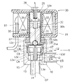
- FIG. 1 is a vertical sectional view showing a pilot-type electrically driven valve according to the first embodiment.
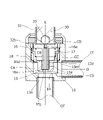
- FIG. 2 is a cross-sectional view showing a main valve body and a sub valve body in a disassembled state.
- FIG. 3 is a cross-sectional view of a main part for explaining the operation of the pilot type electric drive valve, and shows a closed state.
- FIG. 4 is a cross-sectional view of a main part for explaining the operation of the pilot type electric drive valve, and shows a state in which the pilot valve body is separated from the sub valve body.
- FIG. 5 is a cross-sectional view of a main part for explaining the operation of the pilot type electric drive valve, and shows a state in which the auxiliary valve body has started to separate from the main valve body.
- FIG. 1 is a vertical sectional view showing a pilot-type electrically driven valve according to the first embodiment.
- FIG. 2 is a cross-sectional view showing a main valve body and a sub valve body in a dis
- FIG. 6 is a cross-sectional view of a main part for explaining the operation of the pilot type electric drive valve, and shows a state in which the auxiliary valve body is in contact with the guide pipe.
- FIG. 7 is a cross-sectional view of a main part for explaining the operation of the pilot type electric drive valve, and shows a valve open state.
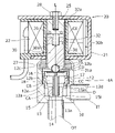
- FIG. 8 is a vertical cross-sectional view showing the pilot type electric drive valve of the second embodiment.
- FIG. 1 is a vertical cross-sectional view showing the pilot type electric drive valve 1 of the first embodiment, and is shown in a state when the valve is closed.
- the pilot type electric drive valve 1 of the illustrated example is used for a refrigerating cycle such as a cooler, and is used in combination with an electromagnetic actuator 20.
- the pilot-type electrically driven valve 1 includes a valve body 10, a main valve body 15 slidably fitted into the valve body 10, and a sub-valve body 16 slidably fitted into the main valve body 15.
- L be the axis of the pilot type electric drive valve 1.
- the valve body 10 is provided with a valve chamber CA inside, and has a bottomed cylindrical shape in which a side wall 12 and a bottom wall 13 are connected in series.
- An outlet opening 13a is formed in the center of the bottom wall 13, and the upper end of the outlet opening 13a constitutes the valve seat 14.
- the outflow pipe OT is connected and fixed to the bottom wall 13 by brazing or the like so as to communicate with the outlet opening 13a.
- the side wall 12 of the valve body 10 is connected to a lower side wall portion 12a on the bottom wall 13 side, an intermediate side wall portion 12b having an inner diameter larger than that of the lower side wall portion 12a, and an upper side wall portion 12c having an inner diameter larger than that of the intermediate side wall portion 12b. It will be set up.
- the upper side wall portion 12c has a thin wall shape so that it can be caulked.
- an inlet opening 12d is formed in the lower side wall portion 12a, and the inflow pipe IT is connected and fixed to the lower side wall portion 12a by brazing or the like so as to communicate with the inlet opening 12d.
- O be the axis of the inflow pipe IT.
- FIG. 2 is a cross-sectional view showing the main valve body 15 and the sub-valve body 16 in a disassembled state, and is shown together with the first coil spring (second elastic member) 17 and the second coil spring (first elastic member) 18.
- the main valve body 15 has a circular tube shape in which the outer diameter gradually decreases toward the lower end. More specifically, the main valve body 15 has a first outer peripheral portion 15a from the lower end thereof, a second outer peripheral portion 15b having a diameter larger than that of the first outer peripheral portion 15a, and a third outer peripheral portion having a diameter larger than that of the second outer peripheral portion 15b. It has a portion 15c and a fourth outer peripheral portion 15d having a diameter larger than that of the third outer peripheral portion 15c.
- the main valve body 15 has a first inner peripheral portion 15e from the lower end thereof, a second inner peripheral portion 15f having a diameter larger than that of the first inner peripheral portion 15e, and a third inner peripheral portion having a diameter larger than that of the second inner peripheral portion 15f. It has a portion 15g and a fourth inner peripheral portion 15h having a diameter larger than that of the third inner peripheral portion 15g.
- the first inner peripheral portion 15e is formed on the radial inner side of the first outer peripheral portion 15a, and the second inner peripheral portion 15f and the third inner peripheral portion 15g are formed on the radial inner side of the second outer peripheral portion 15b.
- the inner peripheral portion 15h of 4 is formed on the inner side in the radial direction of the third outer peripheral portion 15c and the fourth outer peripheral portion 15d.
- a tapered portion 15i is formed between the first outer peripheral portion 15a and the lower end of the main valve body 15, and a first inner circumference is formed between the first inner peripheral portion 15e and the lower end of the main valve body 15.
- a reduced diameter opening (second pilot port) 15j having an inner diameter smaller than that of the portion 15e is formed.
- a first pressure equalizing hole 15k is formed so as to penetrate between the first inner peripheral portion 15e and the first outer peripheral portion 15a, and between the second inner peripheral portion 15f and the second outer peripheral portion 15b.
- a second pressure equalizing hole 15 m is formed so as to penetrate through the above.
- the inner diameter of the first pressure equalizing hole 15k is larger than the inner diameter of the second pressure equalizing hole 15m, but is not limited to this.
- the auxiliary valve body 16 has a shaft portion 16a and a disk portion 16b coaxially connected at the upper end of the shaft portion 16a.
- a counterbore surface 16c is formed coaxially with the shaft portion 16a on the upper surface of the disk portion 16b so as to be one step lower than the periphery.
- the communication hole 16d formed inside the shaft portion 16a is opened at the lower end of the shaft portion 16a and the upper surface of the disk portion 16b.
- a diameter-reduced portion (first pilot port) 16e having a diameter smaller than that of the other portions is formed.
- the lower end of the second coil spring 18 abuts on the stepped surface 12e (FIG. 1) between the lower side wall portion 12a and the intermediate side wall portion 12b of the valve body 10, and the upper end thereof is the main.
- the second coil spring 18 abuts on the stepped surface 15p (FIG. 2) between the third outer peripheral portion 15c and the fourth outer peripheral portion 15d of the valve body 15, and the second coil spring 18 urges the main valve body 15 upward with respect to the valve body 10. are doing.
- the lower surface (top surface) of the disk portion 16b of the auxiliary valve body 16 the outer peripheral surface (inner inner peripheral surface) of the shaft portion 16a, the second inner peripheral portion 15f of the main valve body 15, and the third inner peripheral surface.
- the inner peripheral portion 15g and the fourth inner peripheral portion 15h (outer inner peripheral surface) and the stepped surface 15r (bottom surface) between the first inner peripheral portion 15e and the second inner peripheral portion 15f of the main valve body 15 are internally leveled.
- a pressure chamber CB is formed.
- a stepped surface 15p top surface between the third outer peripheral portion 15c and the fourth outer peripheral portion 15d of the main valve body 15, and the second outer peripheral portion 15b and the third outer peripheral portion 15c (inside inside) of the main valve body 15.
- An external pressure equalizing chamber CC is formed.
- the lower end of the first coil spring 17 abuts on the stepped surface 15q (FIG. 2) between the second inner peripheral portion 15f of the main valve body 15 and the third inner peripheral portion 15g, and the upper end thereof is the auxiliary valve body 16.
- the first coil spring 17 is in contact with the lower surface of the disk portion 16b and is urged so that the auxiliary valve body 16 and the main valve body 15 are separated from each other along the axis L direction.
- the electromagnetic actuator 20 is arranged on a coil unit 22 for energization excitation, a housing 21 arranged so as to cover the outer periphery of the coil unit 22, and a bolt 28 arranged on the upper inner peripheral side of the coil unit 22. It is provided with a bottomed cylindrical or columnar suction element 25 fixed to the housing 21 and a plunger 30 arranged to face the suction element 25.
- a holding hole 31 is provided at the tip of the plunger 30.
- a pilot valve body 35 made of a ball is housed in the holding hole 31.
- the pilot valve body 35 is fixed by caulking the caulked portion 31a that protrudes in a cylindrical shape from the lower end of the plunger 30 in a state where a part of the lower surface thereof is exposed.
- a back pressure chamber CD is formed between the plunger 30 and the accessory valve body 16.
- a vertical hole (spring chamber) 30a and a horizontal hole (pressure equalizing hole) 30b into which a valve closing spring 26 made of a coil spring is inserted and locked are formed in the upper part of the plunger 30.
- a guide pipe 32 is arranged between the coil unit 22 and the suction element 25.
- a plunger 30 is slidably fitted in the guide pipe 32.
- the upper end 32a of the guide pipe 32 is fixed to the outer peripheral step portion of the suction element 25 by TIG welding or the like.
- the outer peripheral portion of the lower end flange-shaped portion 32b of the guide pipe 32 is in contact with the stepped surface between the intermediate side wall portion 12b and the upper side wall portion 12c of the valve body 10.
- the lower end flange-shaped portion 32b of the guide pipe 32 has the ring-shaped member 27 and the side wall 12 by caulking the upper side wall portion 12c of the valve body 10 inward with the ring-shaped member 27 placed on the upper surface thereof. It is fixed so that it is sandwiched between them. Further, the upper side wall portion 12c, the ring-shaped member 27, and the guide pipe 32 are hermetically sealed and fixed by soldering.
- the operation of the pilot type electric drive valve 1 will be described.
- the fluid pressure at the time of valve closing in the inflow pipe IT is P1
- the pressure in the valve chamber upper space CF (see FIG. 6)
- the fluid pressure at the time of valve closing (pressure in the outlet opening 13a) in the outflow pipe OT is P3.
- the valve chamber upper space CF is a space partitioned when the auxiliary valve body 16 rises, but in the present specification, for convenience, the space opposite to the external pressure equalizing chamber CC with the upper end portion of the main valve body 15 sandwiched in the axial direction. Will be described as the valve chamber upper space CF.
- the outlet pressure (pressure in the outlet opening 13a) P3 is assumed to be zero.
- FIG. 3 to 7 are cross-sectional views of a main part for explaining the operation of the pilot type electric drive valve 1.
- FIG. 3 shows a state in which the main valve body 15 is closed.
- the pilot valve body 35 closes the reduced diameter portion 16e of the communication hole 16d of the auxiliary valve body 16, and the tapered portion 15i of the main valve body 15 is seated on the valve seat 14.
- the fluid introduced from the inflow pipe IT through the inlet opening 12d into the valve chamber CA is between the outer peripheral surface of the main valve body 15 and the inner peripheral surface of the valve body 10 (between the sliding surfaces).
- the fluid introduced into the back pressure chamber CD passes between the outer peripheral surface of the plunger 30 and the inner peripheral surface of the guide pipe 32 (between the sliding surfaces), the horizontal hole 30b, and the vertical hole 30a with reference to FIG. It is also guided to the gap space CE formed between the lower end surface of the suction element 25 and the plunger 30.
- the plunger 30 In the pilot-type electric drive valve 1 in the closed state, when the coil unit 22 is energized from a power source (not shown), the plunger 30 is attracted to and attracted to the suction element 25, whereby, as shown in FIG. 4, the pilot The valve body 35 rises in the valve opening direction. Since the internal pressures of the back pressure chamber CD and the gap space CE are equal, the operation of the plunger 30 is not hindered.
- the back pressure chamber CD is filled with a fluid having a pressure substantially equal to the fluid pressure P1 in the inflow pipe IT, the auxiliary valve body 16 is urged downward by the pressure, and the pilot valve body 35 is immediately urged. Does not follow.
- the auxiliary valve body 16 when the reduced diameter portion 16e of the auxiliary valve body 16 is opened by the ascent of the pilot valve body 35, the fluid in the back pressure chamber CD flows out to the outlet opening 13a through the communication hole 16d (see FIG. 4). ). At this time, since the disk portion 16b is urged from below by the fluid pressure P1 in the internal pressure equalizing chamber CB and the urging force of the first coil spring 17, FIG. As shown in, the accessory valve body 16 also starts to rise. Further, as shown in FIG. 6, the auxiliary valve body 16 is locked by the outer periphery of the upper surface of the disk portion 16b coming into contact with the lower surface of the lower end flange-shaped portion 32b of the guide pipe 32.
- the valve chamber upper space CF is not partitioned as a space distinguishable from the back pressure chamber CD and is connected to the back pressure chamber CD, so that the pressure P2 Is equal to the pressure in the back pressure chamber CD. Further, the pressure of the back pressure chamber CD is almost the same as that of P3.
- the forces that urge the main valve body 15 downward are the fluid pressure P1 (the differential pressure between P1 and P3 if P3 is not zero) in the internal pressure equalizing chamber CB and the urging force of the first coil spring 17. .
- the pressure receiving area (the area of the surfaces facing each other along the axis L, the same applies hereinafter) of the main valve body 15 of the external pressure equalizing chamber CC and the valve chamber upper space CF is set to S1 and the internal equalizing is performed.
- the pressure receiving area of the pressure chamber CB is S2, S1 ⁇ S2.
- the spring force of the first coil spring 17 is K1 and the spring force of the second coil spring 18 is K2, then K1 ⁇ K2.
- the left side of equation (1) represents the force to push upward, and the right side represents the force to push downward. (P1-P2) x S1 + K2 ⁇ P1 x S2 + K1 (1)
- Equation (2) is obtained by modifying equation (1).
- the tapered portion 15i separates from the valve seat 14, so that the fluid flowing from the inflow pipe IT into the valve chamber CA flows out to the outflow pipe OT through the valve seat 14 and the outlet opening 13a. .. As shown in FIG. 7, the main valve body 15 is locked to the valve opening position when its upper end abuts on the lower surface of the lower end flange-shaped portion 32b of the guide pipe 32.
- the main valve body 15 does not rise immediately, and further rises after a pressure change in the internal pressure equalizing chamber CB occurs. Then, the valve seat 14 is opened. Therefore, the flow rate of the fluid flowing from the inflow pipe IT to the outflow pipe OT at the time of valve opening can be gradually increased, and the noise generated thereby can be effectively suppressed.
- the spring force K2 of the second coil spring 18 is increased or decreased with respect to the spring force K1 of the first coil spring 17.
- P1 that raises the main valve body 15 can be arbitrarily changed.
- the diameter of the first pressure equalizing hole 15k is reduced, the speed at which the pressure in the internal pressure equalizing chamber CB and the external pressure equalizing chamber CC decreases becomes slow, and the timing for raising the main valve body 15 can be delayed.
- P3 is set to zero, but if P3 is not zero, the main valve body 15 starts to rise when the differential pressure (P1-P3) becomes less than a predetermined value. Assuming that the differential pressure at which the main valve body starts to rise is the threshold value ⁇ P, the timing at which the main valve body rises can be delayed if the threshold value is small.
- FIG. 8 is a vertical cross-sectional view showing the pilot type electric drive valve 1A of the second embodiment, and is shown in a state when the valve is closed.
- the pilot type electric drive valve 1A of the present embodiment differs from the first embodiment in that it does not have a first pressure equalizing hole.
- the main valve body 15 can be kept in the closed position until the differential pressure (P1-P3) between P3 and the internal pressure P1 of the external pressure equalizing chamber CC becomes equal to or less than the threshold value ⁇ P.
- the present invention is not limited to the above-described embodiment.
- any component of the above-described embodiment can be modified.
- any component can be added or omitted in the above-described embodiment.
- a motor type actuator having a screw elevating mechanism may be used, or a normally open type electromagnetic actuator may be used.
Landscapes
- Engineering & Computer Science (AREA)
- General Engineering & Computer Science (AREA)
- Mechanical Engineering (AREA)
- Magnetically Actuated Valves (AREA)
- Fluid-Driven Valves (AREA)
Priority Applications (1)
| Application Number | Priority Date | Filing Date | Title |
|---|---|---|---|
| CN202180044010.3A CN116075662A (zh) | 2020-10-08 | 2021-09-21 | 先导式电驱动阀 |
Applications Claiming Priority (2)
| Application Number | Priority Date | Filing Date | Title |
|---|---|---|---|
| JP2020-170545 | 2020-10-08 | ||
| JP2020170545A JP7329848B2 (ja) | 2020-10-08 | 2020-10-08 | パイロット式電気的駆動弁 |
Publications (1)
| Publication Number | Publication Date |
|---|---|
| WO2022075057A1 true WO2022075057A1 (ja) | 2022-04-14 |
Family
ID=81126490
Family Applications (1)
| Application Number | Title | Priority Date | Filing Date |
|---|---|---|---|
| PCT/JP2021/034590 Ceased WO2022075057A1 (ja) | 2020-10-08 | 2021-09-21 | パイロット式電気的駆動弁 |
Country Status (3)
| Country | Link |
|---|---|
| JP (1) | JP7329848B2 (https=) |
| CN (1) | CN116075662A (https=) |
| WO (1) | WO2022075057A1 (https=) |
Citations (1)
| Publication number | Priority date | Publication date | Assignee | Title |
|---|---|---|---|---|
| JP2010138925A (ja) * | 2008-12-09 | 2010-06-24 | Kayaba Ind Co Ltd | ソレノイドバルブ |
Family Cites Families (5)
| Publication number | Priority date | Publication date | Assignee | Title |
|---|---|---|---|---|
| JPH10338116A (ja) * | 1997-06-09 | 1998-12-22 | Denso Corp | 電磁弁 |
| EP2495482B1 (en) * | 2009-10-30 | 2018-12-12 | Eagle Industry Co., Ltd. | Solenoid valve |
| JP6130684B2 (ja) * | 2013-02-15 | 2017-05-17 | Kyb株式会社 | ソレノイドバルブ |
| CN105782153A (zh) * | 2016-05-04 | 2016-07-20 | 宁波市加力特机械有限公司 | 电动平台液压站压力补偿阀 |
| EP3744978B1 (en) * | 2018-01-26 | 2023-11-15 | Eagle Industry Co., Ltd. | Capacity control valve |
-
2020
- 2020-10-08 JP JP2020170545A patent/JP7329848B2/ja active Active
-
2021
- 2021-09-21 WO PCT/JP2021/034590 patent/WO2022075057A1/ja not_active Ceased
- 2021-09-21 CN CN202180044010.3A patent/CN116075662A/zh active Pending
Patent Citations (1)
| Publication number | Priority date | Publication date | Assignee | Title |
|---|---|---|---|---|
| JP2010138925A (ja) * | 2008-12-09 | 2010-06-24 | Kayaba Ind Co Ltd | ソレノイドバルブ |
Also Published As
| Publication number | Publication date |
|---|---|
| CN116075662A (zh) | 2023-05-05 |
| JP7329848B2 (ja) | 2023-08-21 |
| JP2022062497A (ja) | 2022-04-20 |
Similar Documents
| Publication | Publication Date | Title |
|---|---|---|
| KR102336833B1 (ko) | 가변 용량 압축기용 제어 밸브 | |
| JP5873451B2 (ja) | 弁装置 | |
| CN111279076A (zh) | 容量控制阀及容量控制阀的控制方法 | |
| JP2018021646A (ja) | 感圧制御弁 | |
| JP2018040385A (ja) | 電磁弁 | |
| KR102222565B1 (ko) | 제어밸브 | |
| JP6709926B1 (ja) | 電動弁 | |
| US4275758A (en) | Pressure control valve assembly | |
| JP2001153256A (ja) | 可変容量型圧縮機用制御弁 | |
| WO2017168942A1 (ja) | 電動弁 | |
| CN109578659B (zh) | 流量控制阀 | |
| JP2017110540A (ja) | 可変容量型圧縮機用制御弁 | |
| JP6368897B2 (ja) | 制御弁 | |
| CN112997028A (zh) | 流路切换阀 | |
| CN110792786B (zh) | 电磁阀 | |
| WO2022075057A1 (ja) | パイロット式電気的駆動弁 | |
| JP2009250396A (ja) | 減衰力調整式油圧緩衝器 | |
| CN114096775A (zh) | 容量控制阀 | |
| US12173773B2 (en) | Damping force adjustable shock absorber | |
| JP7333045B2 (ja) | 流量制御弁 | |
| JP5453175B2 (ja) | パイロット式電磁弁 | |
| JP2021134908A (ja) | リリーフ弁 | |
| JP2019138194A (ja) | 可変容量型圧縮機用制御弁 | |
| JP2006188961A (ja) | 可変容量圧縮機用制御弁 | |
| JP6175630B2 (ja) | 制御弁 |
Legal Events
| Date | Code | Title | Description |
|---|---|---|---|
| 121 | Ep: the epo has been informed by wipo that ep was designated in this application |
Ref document number: 21877358 Country of ref document: EP Kind code of ref document: A1 |
|
| NENP | Non-entry into the national phase |
Ref country code: DE |
|
| 122 | Ep: pct application non-entry in european phase |
Ref document number: 21877358 Country of ref document: EP Kind code of ref document: A1 |