WO2022074716A1 - 電力変換装置の制御装置 - Google Patents
電力変換装置の制御装置 Download PDFInfo
- Publication number
- WO2022074716A1 WO2022074716A1 PCT/JP2020/037759 JP2020037759W WO2022074716A1 WO 2022074716 A1 WO2022074716 A1 WO 2022074716A1 JP 2020037759 W JP2020037759 W JP 2020037759W WO 2022074716 A1 WO2022074716 A1 WO 2022074716A1
- Authority
- WO
- WIPO (PCT)
- Prior art keywords
- value
- power
- unit
- switch
- control device
- Prior art date
- Legal status (The legal status is an assumption and is not a legal conclusion. Google has not performed a legal analysis and makes no representation as to the accuracy of the status listed.)
- Ceased
Links
Images

Classifications
-
- H—ELECTRICITY
- H02—GENERATION; CONVERSION OR DISTRIBUTION OF ELECTRIC POWER
- H02M—APPARATUS FOR CONVERSION BETWEEN AC AND AC, BETWEEN AC AND DC, OR BETWEEN DC AND DC, AND FOR USE WITH MAINS OR SIMILAR POWER SUPPLY SYSTEMS; CONVERSION OF DC OR AC INPUT POWER INTO SURGE OUTPUT POWER; CONTROL OR REGULATION THEREOF
- H02M7/00—Conversion of AC power input into DC power output; Conversion of DC power input into AC power output
- H02M7/42—Conversion of DC power input into AC power output without possibility of reversal
- H02M7/44—Conversion of DC power input into AC power output without possibility of reversal by static converters
- H02M7/48—Conversion of DC power input into AC power output without possibility of reversal by static converters using discharge tubes with control electrode or semiconductor devices with control electrode
- H02M7/53—Conversion of DC power input into AC power output without possibility of reversal by static converters using discharge tubes with control electrode or semiconductor devices with control electrode using devices of a triode or transistor type requiring continuous application of a control signal
- H02M7/537—Conversion of DC power input into AC power output without possibility of reversal by static converters using discharge tubes with control electrode or semiconductor devices with control electrode using devices of a triode or transistor type requiring continuous application of a control signal using semiconductor devices only, e.g. single switched pulse inverters
- H02M7/539—Conversion of DC power input into AC power output without possibility of reversal by static converters using discharge tubes with control electrode or semiconductor devices with control electrode using devices of a triode or transistor type requiring continuous application of a control signal using semiconductor devices only, e.g. single switched pulse inverters with automatic control of output wave form or frequency
-
- H—ELECTRICITY
- H02—GENERATION; CONVERSION OR DISTRIBUTION OF ELECTRIC POWER
- H02M—APPARATUS FOR CONVERSION BETWEEN AC AND AC, BETWEEN AC AND DC, OR BETWEEN DC AND DC, AND FOR USE WITH MAINS OR SIMILAR POWER SUPPLY SYSTEMS; CONVERSION OF DC OR AC INPUT POWER INTO SURGE OUTPUT POWER; CONTROL OR REGULATION THEREOF
- H02M7/00—Conversion of AC power input into DC power output; Conversion of DC power input into AC power output
- H02M7/42—Conversion of DC power input into AC power output without possibility of reversal
- H02M7/44—Conversion of DC power input into AC power output without possibility of reversal by static converters
- H02M7/48—Conversion of DC power input into AC power output without possibility of reversal by static converters using discharge tubes with control electrode or semiconductor devices with control electrode
- H02M7/53—Conversion of DC power input into AC power output without possibility of reversal by static converters using discharge tubes with control electrode or semiconductor devices with control electrode using devices of a triode or transistor type requiring continuous application of a control signal
- H02M7/537—Conversion of DC power input into AC power output without possibility of reversal by static converters using discharge tubes with control electrode or semiconductor devices with control electrode using devices of a triode or transistor type requiring continuous application of a control signal using semiconductor devices only, e.g. single switched pulse inverters
- H02M7/5387—Conversion of DC power input into AC power output without possibility of reversal by static converters using discharge tubes with control electrode or semiconductor devices with control electrode using devices of a triode or transistor type requiring continuous application of a control signal using semiconductor devices only, e.g. single switched pulse inverters in a bridge configuration
- H02M7/53871—Conversion of DC power input into AC power output without possibility of reversal by static converters using discharge tubes with control electrode or semiconductor devices with control electrode using devices of a triode or transistor type requiring continuous application of a control signal using semiconductor devices only, e.g. single switched pulse inverters in a bridge configuration with automatic control of output voltage or current
-
- H—ELECTRICITY
- H02—GENERATION; CONVERSION OR DISTRIBUTION OF ELECTRIC POWER
- H02M—APPARATUS FOR CONVERSION BETWEEN AC AND AC, BETWEEN AC AND DC, OR BETWEEN DC AND DC, AND FOR USE WITH MAINS OR SIMILAR POWER SUPPLY SYSTEMS; CONVERSION OF DC OR AC INPUT POWER INTO SURGE OUTPUT POWER; CONTROL OR REGULATION THEREOF
- H02M1/00—Details of apparatus for conversion
- H02M1/08—Circuits specially adapted for the generation of control voltages for semiconductor devices incorporated in static converters
-
- H—ELECTRICITY
- H02—GENERATION; CONVERSION OR DISTRIBUTION OF ELECTRIC POWER
- H02M—APPARATUS FOR CONVERSION BETWEEN AC AND AC, BETWEEN AC AND DC, OR BETWEEN DC AND DC, AND FOR USE WITH MAINS OR SIMILAR POWER SUPPLY SYSTEMS; CONVERSION OF DC OR AC INPUT POWER INTO SURGE OUTPUT POWER; CONTROL OR REGULATION THEREOF
- H02M1/00—Details of apparatus for conversion
- H02M1/12—Arrangements for reducing harmonics from AC input or output
- H02M1/126—Arrangements for reducing harmonics from AC input or output using passive filters
-
- H—ELECTRICITY
- H02—GENERATION; CONVERSION OR DISTRIBUTION OF ELECTRIC POWER
- H02M—APPARATUS FOR CONVERSION BETWEEN AC AND AC, BETWEEN AC AND DC, OR BETWEEN DC AND DC, AND FOR USE WITH MAINS OR SIMILAR POWER SUPPLY SYSTEMS; CONVERSION OF DC OR AC INPUT POWER INTO SURGE OUTPUT POWER; CONTROL OR REGULATION THEREOF
- H02M1/00—Details of apparatus for conversion
- H02M1/32—Means for protecting converters other than automatic disconnection
-
- H—ELECTRICITY
- H02—GENERATION; CONVERSION OR DISTRIBUTION OF ELECTRIC POWER
- H02M—APPARATUS FOR CONVERSION BETWEEN AC AND AC, BETWEEN AC AND DC, OR BETWEEN DC AND DC, AND FOR USE WITH MAINS OR SIMILAR POWER SUPPLY SYSTEMS; CONVERSION OF DC OR AC INPUT POWER INTO SURGE OUTPUT POWER; CONTROL OR REGULATION THEREOF
- H02M1/00—Details of apparatus for conversion
- H02M1/0003—Details of control, feedback or regulation circuits
- H02M1/0009—Devices or circuits for detecting current in a converter
Definitions
- This disclosure relates to a control device for a power conversion device.
- Patent Document 1 discloses a control device for a power conversion device. According to the control device, after the AC voltage synchronized with the voltage of the power system is output from the power conversion device at startup, the control mode of the power conversion device is switched to suppress the inrush current from flowing to the power conversion device. do.
- control device described in Patent Document 1 controls the power conversion device using the value of the output voltage from the inverter. Therefore, a voltage sensor for detecting the output voltage from the inverter is required.
- An object of the present disclosure is to provide a control device for a power conversion device capable of suppressing an inrush current from flowing through the power conversion device with a simple configuration.
- the control device of the power conversion device is a power conversion device in which a power converter, a filter, and a switch are sequentially connected in series from the side of the DC power supply between the DC power supply and the AC power supply.
- a calculation unit that calculates an estimated value of AC power output by the power converter from the value of the AC current flowing between the power converter and the filter and the value of the impedance of the filter, and the switch are opened.
- the target value and the estimated value of the electric power calculated based on the value of the AC current flowing between the filter and the switch and the value of the AC voltage applied between the switch and the AC power supply.
- the operation of the power converter is controlled so that the difference between the current value and the current value is within the preset allowable range, and when the difference between the target value and the estimated value is within the preset allowable range, the opening / closing is performed. It was equipped with a control unit that closes the vessel.
- the control device closes the switch when the difference between the target value and the estimated value of the AC power output by the power converter is within a preset allowable range. Therefore, it is possible to suppress the inrush current from flowing through the power converter with a simple configuration.
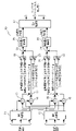
- FIG. 1 It is a block diagram of the power system to which the control device of the power conversion device in Embodiment 1 is applied. It is a block diagram of the control device of the power conversion device in Embodiment 1.
- FIG. It is a block diagram of the main part of the control device of the power conversion device in Embodiment 1. It is a flowchart for demonstrating the outline of the operation of the control device of the power conversion device in Embodiment 1. It is a hardware block diagram of the control device of the power conversion device in Embodiment 1.
- FIG. 1 It is a block diagram of the power system to which the control device of the power conversion device in Embodiment 1 is applied. It is a block diagram of the control device of the power conversion device in Embodiment 1.
- FIG. 1 It is a block diagram of the main part of the control device of the power conversion device in Embodiment 1. It is a flowchart for demonstrating the outline of the operation of the control device of the power conversion device in Embodiment 1. It is a hardware
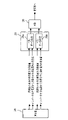
- FIG. 1 is a configuration diagram of a power system to which the control device of the power conversion device according to the first embodiment is applied.
- the power system of FIG. 1 includes a DC power supply 1, an AC power supply 2, and a power conversion device 3.
- the DC power supply 1 is a solar cell.
- the AC power supply 2 is a power system operated by an electric power company or the like.
- the power conversion device 3 is connected between the DC power supply 1 and the AC power supply 2.
- the power converter 3 includes a power converter 4, a harmonic filter 5, a switch 6, a first current detector 7, a second current detector 8, a voltage detector 9, and a control device 10.
- the power converter 4, the harmonic filter 5, and the switch 6 are connected in series in order from the DC power supply 1 side.
- the power converter 4 is provided so as to be able to convert the DC power from the DC power source 1 into AC power.
- the harmonic filter 5 is provided so as to be able to suppress the harmonics of the direct current output from the power converter 4.
- the switch 6 is provided so that the wiring between the harmonic filter 5 and the AC power supply 2 can be closed or opened.
- the first current detector 7 is provided so that the value of the alternating current flowing between the power converter 4 and the harmonic filter 5 can be detected as the value of the inverter output current.
- the second current detector 8 is provided so that the value of the alternating current flowing between the harmonic filter 5 and the switch 6 can be detected as the value of the system current.
- the voltage detector 9 is provided so that the value of the AC voltage applied between the switch 6 and the AC power supply 2 can detect the value of the system voltage.
- the control device 10 is provided so as to be able to control the power converter 4 based on the detection value of the first current detector 7, the detection value of the second current detector 8, and the detection value of the voltage detector 9.
- FIG. 2 is a block diagram of the control device of the power conversion device according to the first embodiment.
- the control device 10 adds the first conversion unit 11, the second conversion unit 12, the first multiplication unit 13, the second multiplication unit 14, the third multiplication unit 15, and the fourth multiplication unit 16.
- Unit 17 first subtraction unit 18, first switching unit 19, second switching unit 20, third switching unit 21, fourth switching unit 22, second subtraction unit 23, third subtraction unit 24, and active power control unit 25.
- the first conversion unit 11 receives input of information on the value of the system voltage.
- the first conversion unit 11 converts the value of the three-phase AC voltage into the value of the d-axis voltage and the value of the q-axis voltage by dq conversion.
- the first conversion unit 11 outputs information on the value of the d-axis voltage and information on the value of the q-axis voltage.
- the second conversion unit 12 receives input of information on the value of the system current.
- the second conversion unit 12 converts the value of the three-phase alternating current into the value of the d-axis current and the value of the q-axis current by dq conversion.
- the second conversion unit 12 outputs information on the value of the d-axis current and information on the value of the q-axis current.
- the first multiplication unit 13 receives input of d-axis voltage value information from the first conversion unit 11.
- the first multiplication unit 13 receives input of information on the value of the d-axis current from the second conversion unit 12.
- the first multiplication unit 13 calculates a value obtained by multiplying the value of the d-axis voltage by the value of the d-axis current.
- the first multiplication unit 13 outputs information on the value obtained by multiplying the value of the d-axis voltage by the value of the d-axis current.
- the second multiplication unit 14 receives input of information on the value of the q-axis voltage from the first conversion unit 11.
- the second multiplication unit 14 receives input of information on the value of the q-axis current from the second conversion unit 12.
- the second multiplication unit 14 calculates a value obtained by multiplying the value of the q-axis voltage by the value of the q-axis current.
- the second multiplication unit 14 outputs information on the value obtained by multiplying the value of the q-axis voltage by the value of the q-axis current.
- the third multiplication unit 15 receives input of information on the value of the q-axis voltage from the first conversion unit 11.
- the third multiplication unit 15 receives input of information on the value of the d-axis current from the second conversion unit 12.
- the third multiplication unit 15 calculates a value obtained by multiplying the value of the q-axis voltage by the value of the d-axis current.
- the third multiplication unit 15 outputs information on the value obtained by multiplying the value of the q-axis voltage by the value of the d-axis current.
- the fourth multiplication unit 16 receives input of d-axis voltage value information from the first conversion unit 11.
- the fourth multiplication unit 16 receives input of information on the value of the q-axis current from the second conversion unit 12.
- the fourth multiplication unit 16 calculates a value obtained by multiplying the value of the d-axis voltage by the value of the q-axis current.
- the fourth multiplication unit 16 outputs information on the value obtained by multiplying the value of the d-axis voltage by the value of the q-axis current.
- the addition unit 17 accepts the input of the output value information of the first multiplication unit 13.
- the addition unit 17 accepts input of information on the output value of the second multiplication unit 14.
- the addition unit 17 calculates the feedback value of the active power by adding the output value of the second multiplication unit 14 to the output value of the first multiplication unit 13.
- the addition unit 17 outputs information on the feedback value of the active power.
- the first subtraction unit 18 accepts the input of the output value information of the third multiplication unit 15.
- the first subtraction unit 18 receives the input of the output value of the fourth multiplication unit 16.
- the first subtraction unit 18 calculates the feedback value of the reactive power by subtracting the output value of the fourth multiplication unit 16 from the output value of the third multiplication unit 15.
- the first subtraction unit 18 outputs information on the feedback value of the reactive power.
- the first switching unit 19 accepts the input of the information of the target value of the active power at the time of synchronization adjustment.
- the target value of the active power at the time of synchronization adjustment is a value based on the value of the inverter current and the value of the system voltage when the switch 6 is open.
- the first switching unit 19 receives input of information on the target value of the active power during normal operation.
- the target value of the active power during normal operation is a value based on the value of the system current and the value of the system voltage when the switch 6 is closed.
- the first switching unit 19 switches the output value when a preset condition is satisfied.
- the first switching unit 19 changes the output value information from the information of the target value of the active power during normal operation to the target of the active power at the time of synchronization when the switch 6 changes from the closed state to the open state.
- Switch to value information For example, the first switching unit 19 changes the output value information from the information of the target value of the active power at the time of synchronization to the target of the active power during normal operation when the switch 6 changes from the open state to the closed state. Switch to value information.
- the second switching unit 20 accepts the input of the feedback value of the active power.
- the second switching unit 20 receives an input of an estimated value of active power.
- the estimated active power is calculated based on the inverter output current as the output power required for the voltage value output from the power converter 4 to match the system voltage value when the switch 6 is open. Value.
- the second switching unit 20 switches the output value when a preset condition is satisfied. For example, the second switching unit 20 switches the output value information from the active power feedback value information to the active power estimated value information when the switch 6 changes from the closed state to the open state. For example, the second switching unit 20 switches the output value information from the information of the estimated value of the active power to the information of the feedback value of the active power when the switch 6 changes from the open state to the closed state.
- the third switching unit 21 accepts input of information on the target value of the reactive power at the time of synchronization adjustment.
- the target value of the reactive power at the time of synchronization adjustment is a value based on the value of the inverter current and the value of the system voltage in the state where the switch 6 is open.
- the third switching unit 21 receives input of information on the target value of the reactive power during normal operation.
- the target value of the reactive power during normal operation is a value based on the value of the system current and the value of the system voltage when the switch 6 is closed.
- the third switching unit 21 switches the output value when a preset condition is satisfied.
- the third switching unit 21 changes the output value information from the information of the target value of the reactive power during normal operation to the target of the reactive power at the time of synchronization when the switch 6 changes from the closed state to the open state.
- Switch to value information For example, the third switching unit 21 changes the output value information from the information of the target value of the reactive power at the time of synchronization to the target of the reactive power at the time of normal operation when the switch 6 changes from the open state to the closed state. Switch to value information.
- the fourth switching unit 22 accepts the input of the information of the invalid power feedback value.
- the fourth switching unit 22 receives input of information on the estimated value of the reactive power.
- the estimated value of the reactive power is calculated based on the inverter output current as the output power required for the value of the voltage output from the power converter 4 to match the value of the system voltage in the open state of the switch 6. Value.
- the fourth switching unit 22 switches the output value when a preset condition is satisfied. For example, the fourth switching unit 22 switches the information of the output value from the information of the feedback value of the reactive power to the information of the estimated value of the reactive power when the switch 6 changes from the closed state to the open state. For example, the fourth switching unit 22 switches the output value information from the information of the estimated value of the reactive power to the information of the feedback value of the reactive power when the switch 6 changes from the open state to the closed state.
- the second subtraction unit 23 receives input of output value information from the first switching unit 19.
- the second subtraction unit 23 receives input of output value information from the second switching unit 20.
- the second subtraction unit 23 calculates a value obtained by subtracting the output value of the second switching unit 20 from the output value of the first switching unit 19.
- the second subtraction unit 23 outputs information of a value obtained by subtracting the output value of the second switching unit 20 from the output value of the first switching unit 19.
- the third subtraction unit 24 receives input of output value information from the third switching unit 21.
- the third subtraction unit 24 receives input of output value information from the fourth switching unit 22.
- the third subtraction unit 24 calculates a value obtained by subtracting the output value of the fourth switching unit 22 from the output value of the third switching unit 21.
- the third subtraction unit 24 outputs information of a value obtained by subtracting the output value of the fourth switching unit 22 from the output value of the third switching unit 21.
- the active power control unit 25 accepts the input of the output value information of the second subtraction unit 23.
- the active power control unit 25 calculates the d-axis current command value based on the output value of the second subtraction unit 23.
- the active power control unit 25 outputs information on the d-axis current command value.
- the reactive power control unit 26 accepts the input of the output value information of the third subtraction unit 24.
- the reactive power control unit 26 calculates the q-axis current command value based on the output value of the third subtraction unit 24.
- the reactive power control unit 26 outputs information on the q-axis current command value.
- the current control unit 27 receives input of d-axis current command value information from the active power control unit 25.
- the current control unit 27 receives input of information on the q-axis current command value from the reactive power control unit 26.
- the current control unit 27 outputs information on the d-axis voltage command value and information on the q-axis voltage command value to the inverter gate pulse generation unit that controls the operation of the power converter 4.
- FIG. 3 is a block diagram of a main part of the control device of the power conversion device according to the first embodiment.
- control device 10 includes a calculation unit 28, a comparison unit 29, and a control unit 30.
- the calculation unit 28 calculates the target value of the active power at the time of synchronization adjustment.
- the target value of the active power at the time of synchronization adjustment is the same value as the active power based on the value of the inverter current and the value of the system voltage when the switch 6 is open.
- the calculation unit 28 outputs information on the target value of the active power at the time of synchronization adjustment to the first switching unit 19 (not shown in FIG. 3).
- the calculation unit 28 calculates an estimated value of the active power output by the power converter 4 from the value of the AC current output from the power converter 4 at the time of synchronization adjustment. Specifically, the calculation unit 28 calculates an estimated value of the active voltage output from the power converter 4 from the value of the inverter output current and the value of the impedance of the harmonic filter 5. The calculation unit 28 calculates an estimated value of active power from the value of the inverter output current and the estimated value of the active voltage. The calculation unit 28 outputs the information of the estimated value of the active power to the second switching unit 20 (not shown in FIG. 3).
- the calculation unit 28 calculates the target value of the reactive power at the time of synchronization adjustment.
- the target value of the active power at the time of synchronization adjustment is the same value as the reactive power based on the value of the inverter current and the value of the system voltage when the switch 6 is open.
- the calculation unit 28 outputs the target value of the reactive power at the time of synchronization adjustment to the third switching unit 21 (not shown in FIG. 3).
- the calculation unit 28 calculates an estimated value of the reactive power output by the power converter 4 from the value of the AC current output from the power converter 4 at the time of synchronization adjustment. Specifically, the calculation unit 28 calculates an estimated value of the invalid voltage output from the power converter 4 from the value of the inverter output current and the value of the impedance of the harmonic filter 5. The calculation unit 28 calculates the estimated value of the reactive power from the value of the inverter output current and the estimated value of the invalid voltage. The calculation unit 28 outputs the information of the estimated value of the reactive power to the fourth switching unit 22 (not shown in FIG. 3).
- the comparison unit 29 includes an active power determination unit 29a and an ineffective power determination unit 29b.
- the active power determination unit 29a receives input of information on the target value of the active power at the time of synchronization adjustment from the calculation unit 28.
- the active power determination unit 29a receives input of information on the estimated value of the active power from the calculation unit 28.
- the active power determination unit 29a compares the target value and the estimated value of the active power at the time of synchronization adjustment.
- the active power determination unit 29a determines whether or not the difference between the target value and the estimated value of the active power at the time of synchronization adjustment is within the preset allowable range. For example, the active power determination unit 29a determines whether or not the target value and the estimated value of the active power at the time of synchronization matching match.
- the active power determination unit 29a outputs information on the determination result as to whether or not the target value and the estimated value of the active power at the time of synchronization matching match.
- the ineffective power determination unit 29b receives input of information on the target value of the ineffective power at the time of synchronization adjustment from the calculation unit 28.
- the reactive power determination unit 29b receives input of information on the estimated value of the reactive power from the calculation unit 28.
- the reactive power determination unit 29b compares the target value and the estimated value of the reactive power at the time of synchronization adjustment.
- the reactive power determination unit 29b determines whether or not the difference between the target value and the estimated value of the reactive power at the time of synchronization and synchronization is within a preset allowable range. For example, the reactive power determination unit 29b determines whether or not the target value and the estimated value of the reactive power at the time of synchronization matching match.
- the ineffective power determination unit 29b outputs information on the determination result as to whether or not the target value and the estimated value of the ineffective power at the time of synchronization matching match.
- the control unit 30 receives input of determination result information from the active power determination unit 29a.
- the control unit 30 receives input of determination result information from the reactive power determination unit 29b.
- the control unit 30 switches between opening and closing the switch 6 based on the determination result of the active power determination unit 29a and the determination result of the ineffective power determination unit 29b. For example, the control unit 30 determines that the difference between the target value of the active power and the estimated value at the time of synchronization adjustment is within a preset allowable range, and the difference between the target value and the estimated value of the reactive power at the time of synchronization adjustment. Closes the switch 6 if is within a preset tolerance. For example, the control unit 30 closes the switch 6 when the target value and the estimated value of the active power at the time of synchronization matching match, and when the target value and the estimated value of the reactive power at the time of synchronization matching match.
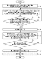
- FIG. 4 is a flowchart for explaining an outline of the operation of the control device of the power conversion device according to the first embodiment.
- step S1 the control device 10 calculates an estimated value of active power and an estimated value of reactive power output by the power converter 4. After that, the control device 10 performs the operation of step S2.
- step S2 the current control unit 27 sets the power converter 4 so that the target value of the active power and the target value of the active power at the time of synchronization matching match the estimated value of the active power and the estimated value of the active power, respectively. Control the operation.
- step S3 the control device 10 determines whether or not the target value of the active power and the target value of the active power at the time of synchronization match the estimated value of the active power and the estimated value of the active power, respectively.
- step S3 If the target value of the active power at the time of synchronization matching does not match the estimated value of the active power in step S3, or if the target value of the active power at the time of synchronization matching does not match the estimated value of the active power, the control device 10 Performs the operation of step S2.
- step S3 When the target value of the active power and the target value of the active power at the time of synchronization matching in step S3 match the estimated value of the active power and the estimated value of the active power, respectively, the control device 10 performs the operation of step S4.
- step S4 the control device 10 closes the switch 6. After that, the control device 10 performs the operation of step S5.
- step S5 the control device 10 operates the power converter 4 so that the feedback value of the active power and the feedback value of the reactive power match the target value of the active power and the target value of the reactive power during normal operation, respectively. To control.
- step S6 the control device 10 determines whether or not there is a request to stop the operation of the power converter 4. If there is no request to stop the operation of the power converter 4 in step S6, the control device 10 performs the operation of step S5. When there is a request to stop the operation of the power converter 4 in step S6, the control device 10 performs the operation of step S7.
- step S7 the control device 10 stops the operation of the power converter 4. After that, the control device 10 performs the operation of step S8.
- step S8 the control device 10 opens the switch 6. After that, the control device 10 ends the operation.
- the control device 10 closes the switch 6 when the difference between the target value of the AC power and the estimated value is within the preset allowable range.
- the synchronization is performed. It can be performed.
- the amplitude, phase angle, and frequency of the voltage output from the power converter 4 and the AC voltage on the input side of the AC power supply 2 at the time of system insertion can be matched. Therefore, it is possible to suppress the inrush current from flowing through the power converter 4 with a simple and inexpensive configuration.
- control device 10 closes the switch 6 when the target value and the estimated value of the AC power match. Therefore, it is possible to more reliably suppress the inrush current from flowing through the power converter 4.
- control device 10 includes a comparison unit 29. Therefore, it is possible to more accurately determine whether or not the target value and the estimated value of the AC power match.
- the control device 10 operates the power converter 4 so that the difference between the power feedback value and the target value of the power during normal operation is within a preset allowable range. To control. Therefore, the power converter 4 can quickly shift to normal operation.
- the DC power supply 1 may be a rectifier.
- the DC power supply 1 may be a battery.
- the DC power supply 1 may be a capacitor.
- the first switching unit 19 may switch the information of the output value when the switch 6 is instructed to open / close. In this case, the information of the output value can be switched even if the control device 10 does not detect the opening / closing of the switch 6.
- the second switching unit 20 may switch the information of the output value when the switch 6 is instructed to open / close. In this case, the information of the output value can be switched even if the control device 10 does not detect the opening / closing of the switch 6.
- the third switching unit 21 may switch the information of the output value when the switch 6 is instructed to open / close. In this case, the information of the output value can be switched even if the control device 10 does not detect the opening / closing of the switch 6.
- the fourth switching unit 22 may switch the information of the output value when the switch 6 is instructed to open / close. In this case, the output value information can be switched even if the control device 10 does not detect the opening / closing of the switch 6.
- the power converter 4 is not limited to the circuit configuration shown in the figure.
- the power converter 4 may have a circuit configuration in which the inverter has multiple levels.
- the power converter 4 may have a circuit configuration in which inverters are connected in a series multi-stage row.
- the power converter 4 may have a circuit configuration in which inverters are connected in parallel.
- the inverter constituting the power converter 4 may be single-phase.
- the harmonic filter 5 is not limited to the circuit configuration shown in the figure.
- the harmonic filter 5 may be used as long as the current flows in the state where the switch 6 is open and the impedance value is known.
- the harmonic filter 5 may be a transformer.
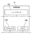
- FIG. 5 is a hardware configuration diagram of the control device of the power conversion device 3 according to the first embodiment.
- Each function of the control device 10 can be realized by a processing circuit.
- the processing circuit comprises at least one processor 100a and at least one memory 100b.
- the processing circuit comprises at least one dedicated hardware 200.
- each function of the control device 10 is realized by software, firmware, or a combination of software and firmware. At least one of the software and firmware is written as a program. At least one of the software and firmware is stored in at least one memory 100b. At least one processor 100a realizes each function of the control device 10 by reading and executing a program stored in at least one memory 100b. At least one processor 100a is also referred to as a central processing unit, a processing unit, an arithmetic unit, a microprocessor, a microcomputer, and a DSP.
- At least one memory 100b is a non-volatile or volatile semiconductor memory such as RAM, ROM, flash memory, EPROM, EEPROM, a magnetic disk, a flexible disk, an optical disk, a compact disk, a mini disk, a DVD, or the like.
- the processing circuit comprises at least one dedicated hardware 200
- the processing circuit may be implemented, for example, as a single circuit, a composite circuit, a programmed processor, a parallel programmed processor, an ASIC, an FPGA, or a combination thereof.
- each function of the control device 10 is realized by a processing circuit.
- each function of the control device 10 is collectively realized by a processing circuit.
- a part may be realized by the dedicated hardware 200, and the other part may be realized by software or firmware.
- the function of the control unit 30 is realized by a processing circuit as dedicated hardware 200, and for functions other than the function of the control unit 30, at least one processor 100a reads a program stored in at least one memory 100b. It may be realized by executing the above.
- the processing circuit realizes each function of the control device 10 by hardware 200, software, firmware, or a combination thereof.
- control device of the power conversion device of the present disclosure can be used for the power system.
Landscapes
- Engineering & Computer Science (AREA)
- Power Engineering (AREA)
- Inverter Devices (AREA)
Abstract
Description
図1は実施の形態1における電力変換装置の制御装置が適用される電力システムの構成図である。
図2は実施の形態1における電力変換装置の制御装置のブロック図である。
図3は実施の形態1における電力変換装置の制御装置の要部のブロック図である。
図4は実施の形態1における電力変換装置の制御装置の動作の概要を説明するためのフローチャートである。
図5は実施の形態1における電力変換装置3の制御装置のハードウェア構成図である。
Claims (4)
- 直流電源と交流電源との間において電力変換器とフィルタと開閉器とが前記直流電源の側から順々に直列に接続された電力変換装置において、前記電力変換器と前記フィルタとの間に流れる交流電流の値と前記フィルタのインピーダンスの値とから前記電力変換器が出力する交流電力の推定値を算出する算出部と、
前記開閉器が開いた状態において、前記フィルタと前記開閉器との間に流れる交流電流の値と前記開閉器と前記交流電源との間にかかる交流電圧の値とに基づいて算出された交流電力の目標値と前記推定値との差が予め設定された許容範囲内となるように前記電力変換器の動作を制御し、前記目標値と前記推定値との差が予め設定された許容範囲内になった場合に前記開閉器を閉じる制御部と、
を備えた電力変換装置の制御装置。 - 前記制御部は、前記目標値と前記推定値とが一致するように前記電力変換装置の動作を制御し、前記目標値と前記推定値とが一致した場合に前記開閉器を閉じる請求項1に記載の電力変換装置の制御装置。
- 前記目標値と前記推定値との差を比較する比較部、
を備え、
前記制御部は、前記比較部の比較において前記目標値と前記推定値との差が予め設定された許容範囲内となった場合に前記開閉器を閉じる請求項1または請求項2に記載の電力変換装置の制御装置。 - 前記制御部は、前記開閉器が閉じた場合に、前記フィルタと前記開閉器との間とに流れる交流電流の値と前記開閉器と前記交流電源との間とにかかる交流電圧の値とに基づいて算出された交流電力のフィードバック値と当該交流電力の目標値との差が予め設定された許容範囲内となるように前記電力変換器の動作を制御する請求項1から請求項3のいずれか1項に記載の電力変換装置の制御装置。
Priority Applications (4)
| Application Number | Priority Date | Filing Date | Title |
|---|---|---|---|
| US17/755,018 US12126277B2 (en) | 2020-10-05 | 2020-10-05 | Control device for power conversion apparatus |
| CN202080070471.3A CN114600363B (zh) | 2020-10-05 | 2020-10-05 | 电力变换装置的控制装置 |
| PCT/JP2020/037759 WO2022074716A1 (ja) | 2020-10-05 | 2020-10-05 | 電力変換装置の制御装置 |
| JP2022506704A JP7287570B2 (ja) | 2020-10-05 | 2020-10-05 | 電力変換装置の制御装置 |
Applications Claiming Priority (1)
| Application Number | Priority Date | Filing Date | Title |
|---|---|---|---|
| PCT/JP2020/037759 WO2022074716A1 (ja) | 2020-10-05 | 2020-10-05 | 電力変換装置の制御装置 |
Publications (1)
| Publication Number | Publication Date |
|---|---|
| WO2022074716A1 true WO2022074716A1 (ja) | 2022-04-14 |
Family
ID=81175211
Family Applications (1)
| Application Number | Title | Priority Date | Filing Date |
|---|---|---|---|
| PCT/JP2020/037759 Ceased WO2022074716A1 (ja) | 2020-10-05 | 2020-10-05 | 電力変換装置の制御装置 |
Country Status (4)
| Country | Link |
|---|---|
| US (1) | US12126277B2 (ja) |
| JP (1) | JP7287570B2 (ja) |
| CN (1) | CN114600363B (ja) |
| WO (1) | WO2022074716A1 (ja) |
Citations (3)
| Publication number | Priority date | Publication date | Assignee | Title |
|---|---|---|---|---|
| JPH09261969A (ja) * | 1996-03-22 | 1997-10-03 | Mitsubishi Electric Corp | インバータ装置 |
| JP2010226871A (ja) * | 2009-03-24 | 2010-10-07 | Toshiba Mitsubishi-Electric Industrial System Corp | 電力供給システム |
| JP2020068552A (ja) * | 2018-10-22 | 2020-04-30 | パナソニックIpマネジメント株式会社 | 電力変換装置 |
Family Cites Families (10)
| Publication number | Priority date | Publication date | Assignee | Title |
|---|---|---|---|---|
| JP2783771B2 (ja) * | 1995-07-13 | 1998-08-06 | 株式会社東芝 | 系統連系インバータ装置の起動運転方法 |
| US7081740B2 (en) * | 2004-12-08 | 2006-07-25 | Kiawe Forest, Llc | Digital duty cycle regulator for DC/DC converters |
| JP6361398B2 (ja) * | 2014-09-16 | 2018-07-25 | 日新電機株式会社 | 系統連系用電力変換装置の制御装置、及び系統連系用電力変換装置 |
| JP5969094B1 (ja) * | 2015-06-24 | 2016-08-10 | 田淵電機株式会社 | 系統連系インバータ装置及び系統連系インバータ装置の系統連系運転起動方法 |
| JP2017046501A (ja) * | 2015-08-27 | 2017-03-02 | パナソニックIpマネジメント株式会社 | 電力変換装置 |
| JP6842953B2 (ja) * | 2017-03-03 | 2021-03-17 | 田淵電機株式会社 | 電力変換装置 |
| WO2019044403A1 (ja) * | 2017-08-31 | 2019-03-07 | 株式会社村田製作所 | 太陽光発電システム、パワーコンディショナ |
| EP3961903A4 (en) * | 2019-04-25 | 2022-04-06 | Mitsubishi Electric Corporation | CONTROL DEVICE |
| US11817774B2 (en) * | 2019-12-10 | 2023-11-14 | Toshiba Mitsubishi-Electric Industrial Systems Corporation | Control device for power converter |
| JP7347683B2 (ja) * | 2020-08-25 | 2023-09-20 | 東芝三菱電機産業システム株式会社 | 電力変換装置の制御装置および電力変換システム |
-
2020
- 2020-10-05 JP JP2022506704A patent/JP7287570B2/ja active Active
- 2020-10-05 US US17/755,018 patent/US12126277B2/en active Active
- 2020-10-05 CN CN202080070471.3A patent/CN114600363B/zh active Active
- 2020-10-05 WO PCT/JP2020/037759 patent/WO2022074716A1/ja not_active Ceased
Patent Citations (3)
| Publication number | Priority date | Publication date | Assignee | Title |
|---|---|---|---|---|
| JPH09261969A (ja) * | 1996-03-22 | 1997-10-03 | Mitsubishi Electric Corp | インバータ装置 |
| JP2010226871A (ja) * | 2009-03-24 | 2010-10-07 | Toshiba Mitsubishi-Electric Industrial System Corp | 電力供給システム |
| JP2020068552A (ja) * | 2018-10-22 | 2020-04-30 | パナソニックIpマネジメント株式会社 | 電力変換装置 |
Also Published As
| Publication number | Publication date |
|---|---|
| CN114600363A (zh) | 2022-06-07 |
| JPWO2022074716A1 (ja) | 2022-04-14 |
| US20220385210A1 (en) | 2022-12-01 |
| CN114600363B (zh) | 2025-07-29 |
| US12126277B2 (en) | 2024-10-22 |
| JP7287570B2 (ja) | 2023-06-06 |
Similar Documents
| Publication | Publication Date | Title |
|---|---|---|
| US10615636B2 (en) | Uninterruptible power supply | |
| US12261549B2 (en) | Control device for applying a power conversion device and power conversion system to control an amplitude and a frequency of a voltage | |
| JP2010068630A (ja) | インバータ制御回路、このインバータ制御回路を備えた系統連系インバータシステム、このインバータ制御回路を実現するためのプログラム、及びこのプログラムを記録した記録媒体 | |
| JP7287570B2 (ja) | 電力変換装置の制御装置 | |
| JP2009171652A (ja) | 電力変換装置 | |
| AU2012364266B2 (en) | Power converter with digital current control circuit | |
| US20220416648A1 (en) | Control device for power converter | |
| US10944336B2 (en) | Power conversion apparatus | |
| JP2016063687A (ja) | 電力変換装置 | |
| JP6852788B2 (ja) | 電力変換装置の制御装置 | |
| JP7156555B2 (ja) | 電力変換器の制御装置 | |
| JP4365376B2 (ja) | 電力変換装置 | |
| US12132394B2 (en) | Controller of power conversion device | |
| KR100685444B1 (ko) | 단상인버터의 병렬제어시스템 | |
| JP7761156B2 (ja) | 制御装置、電力変換装置、電力変換装置の制御方法およびプログラム | |
| JP7859180B2 (ja) | 電力変換装置 | |
| JP2006187089A (ja) | 無停電電源装置及び無停電電源装置の制御方法 | |
| WO2021014540A1 (ja) | 電力変換システム | |
| US10581311B2 (en) | Power conversion device including overcurrent detection with reduced delay | |
| JP7097673B2 (ja) | 系統連系インバータ装置 | |
| JPH07336897A (ja) | 分散電源用インバータ装置及びその制御方法 | |
| WO2024252521A1 (ja) | 電力変換装置 | |
| JP2016100963A (ja) | 系統連系インバータ装置 | |
| JPH099628A (ja) | コンバータ制御装置 | |
| WO2022074803A1 (ja) | 電力変換装置 |
Legal Events
| Date | Code | Title | Description |
|---|---|---|---|
| ENP | Entry into the national phase |
Ref document number: 2022506704 Country of ref document: JP Kind code of ref document: A |
|
| 121 | Ep: the epo has been informed by wipo that ep was designated in this application |
Ref document number: 20956665 Country of ref document: EP Kind code of ref document: A1 |
|
| NENP | Non-entry into the national phase |
Ref country code: DE |
|
| 122 | Ep: pct application non-entry in european phase |
Ref document number: 20956665 Country of ref document: EP Kind code of ref document: A1 |
|
| WWG | Wipo information: grant in national office |
Ref document number: 202080070471.3 Country of ref document: CN |
|
| WWG | Wipo information: grant in national office |
Ref document number: 202217020500 Country of ref document: IN |