WO2022064796A1 - 粘着剤層付き異形偏光板 - Google Patents
粘着剤層付き異形偏光板 Download PDFInfo
- Publication number
- WO2022064796A1 WO2022064796A1 PCT/JP2021/023742 JP2021023742W WO2022064796A1 WO 2022064796 A1 WO2022064796 A1 WO 2022064796A1 JP 2021023742 W JP2021023742 W JP 2021023742W WO 2022064796 A1 WO2022064796 A1 WO 2022064796A1
- Authority
- WO
- WIPO (PCT)
- Prior art keywords
- polarizing plate
- adhesive layer
- sensitive adhesive
- meth
- pressure
- Prior art date
- Legal status (The legal status is an assumption and is not a legal conclusion. Google has not performed a legal analysis and makes no representation as to the accuracy of the status listed.)
- Ceased
Links
Images
Classifications
-
- B—PERFORMING OPERATIONS; TRANSPORTING
- B32—LAYERED PRODUCTS
- B32B—LAYERED PRODUCTS, i.e. PRODUCTS BUILT-UP OF STRATA OF FLAT OR NON-FLAT, e.g. CELLULAR OR HONEYCOMB, FORM
- B32B7/00—Layered products characterised by the relation between layers; Layered products characterised by the relative orientation of features between layers, or by the relative values of a measurable parameter between layers, i.e. products comprising layers having different physical, chemical or physicochemical properties; Layered products characterised by the interconnection of layers
- B32B7/04—Interconnection of layers
- B32B7/12—Interconnection of layers using interposed adhesives or interposed materials with bonding properties
-
- B—PERFORMING OPERATIONS; TRANSPORTING
- B32—LAYERED PRODUCTS
- B32B—LAYERED PRODUCTS, i.e. PRODUCTS BUILT-UP OF STRATA OF FLAT OR NON-FLAT, e.g. CELLULAR OR HONEYCOMB, FORM
- B32B27/00—Layered products comprising a layer of synthetic resin
-
- B—PERFORMING OPERATIONS; TRANSPORTING
- B32—LAYERED PRODUCTS
- B32B—LAYERED PRODUCTS, i.e. PRODUCTS BUILT-UP OF STRATA OF FLAT OR NON-FLAT, e.g. CELLULAR OR HONEYCOMB, FORM
- B32B7/00—Layered products characterised by the relation between layers; Layered products characterised by the relative orientation of features between layers, or by the relative values of a measurable parameter between layers, i.e. products comprising layers having different physical, chemical or physicochemical properties; Layered products characterised by the interconnection of layers
- B32B7/02—Physical, chemical or physicochemical properties
- B32B7/022—Mechanical properties
-
- B—PERFORMING OPERATIONS; TRANSPORTING
- B32—LAYERED PRODUCTS
- B32B—LAYERED PRODUCTS, i.e. PRODUCTS BUILT-UP OF STRATA OF FLAT OR NON-FLAT, e.g. CELLULAR OR HONEYCOMB, FORM
- B32B7/00—Layered products characterised by the relation between layers; Layered products characterised by the relative orientation of features between layers, or by the relative values of a measurable parameter between layers, i.e. products comprising layers having different physical, chemical or physicochemical properties; Layered products characterised by the interconnection of layers
- B32B7/02—Physical, chemical or physicochemical properties
- B32B7/023—Optical properties
-
- C—CHEMISTRY; METALLURGY
- C09—DYES; PAINTS; POLISHES; NATURAL RESINS; ADHESIVES; COMPOSITIONS NOT OTHERWISE PROVIDED FOR; APPLICATIONS OF MATERIALS NOT OTHERWISE PROVIDED FOR
- C09J—ADHESIVES; NON-MECHANICAL ASPECTS OF ADHESIVE PROCESSES IN GENERAL; ADHESIVE PROCESSES NOT PROVIDED FOR ELSEWHERE; USE OF MATERIALS AS ADHESIVES
- C09J201/00—Adhesives based on unspecified macromolecular compounds
-
- C—CHEMISTRY; METALLURGY
- C09—DYES; PAINTS; POLISHES; NATURAL RESINS; ADHESIVES; COMPOSITIONS NOT OTHERWISE PROVIDED FOR; APPLICATIONS OF MATERIALS NOT OTHERWISE PROVIDED FOR
- C09J—ADHESIVES; NON-MECHANICAL ASPECTS OF ADHESIVE PROCESSES IN GENERAL; ADHESIVE PROCESSES NOT PROVIDED FOR ELSEWHERE; USE OF MATERIALS AS ADHESIVES
- C09J7/00—Adhesives in the form of films or foils
- C09J7/30—Adhesives in the form of films or foils characterised by the adhesive composition
- C09J7/38—Pressure-sensitive adhesives [PSA]
-
- G—PHYSICS
- G02—OPTICS
- G02B—OPTICAL ELEMENTS, SYSTEMS OR APPARATUS
- G02B5/00—Optical elements other than lenses
- G02B5/30—Polarising elements
-
- G—PHYSICS
- G02—OPTICS
- G02F—OPTICAL DEVICES OR ARRANGEMENTS FOR THE CONTROL OF LIGHT BY MODIFICATION OF THE OPTICAL PROPERTIES OF THE MEDIA OF THE ELEMENTS INVOLVED THEREIN; NON-LINEAR OPTICS; FREQUENCY-CHANGING OF LIGHT; OPTICAL LOGIC ELEMENTS; OPTICAL ANALOGUE/DIGITAL CONVERTERS
- G02F1/00—Devices or arrangements for the control of the intensity, colour, phase, polarisation or direction of light arriving from an independent light source, e.g. switching, gating or modulating; Non-linear optics
- G02F1/01—Devices or arrangements for the control of the intensity, colour, phase, polarisation or direction of light arriving from an independent light source, e.g. switching, gating or modulating; Non-linear optics for the control of the intensity, phase, polarisation or colour
- G02F1/13—Devices or arrangements for the control of the intensity, colour, phase, polarisation or direction of light arriving from an independent light source, e.g. switching, gating or modulating; Non-linear optics for the control of the intensity, phase, polarisation or colour based on liquid crystals, e.g. single liquid crystal display cells
- G02F1/133—Constructional arrangements; Operation of liquid crystal cells; Circuit arrangements
- G02F1/1333—Constructional arrangements; Manufacturing methods
- G02F1/1335—Structural association of cells with optical devices, e.g. polarisers or reflectors
Definitions
- One embodiment of the present invention relates to a deformed polarizing plate with an adhesive layer.
- Liquid crystal displays are widely used in televisions, notebook computers, monitors, smartphones, etc. because they are thin, lightweight, and have low power consumption.
- the liquid crystal display device has a liquid crystal panel member in which polarizing plates are bonded to both sides of the liquid crystal cell with an adhesive, and the display is performed by controlling the light from the backlight member by the liquid crystal panel member.
- the shape of the main surface of an LCD is generally rectangular, but in recent years, LCDs used in smartphones, in-vehicle monitors, etc. have adopted display devices having shapes other than rectangles and squares (odd shapes). In this case, a deformed polarizing plate with an adhesive layer is used.
- a non-contact portion that does not come into contact with the pressure-sensitive adhesive layer is formed at the end of the polarizing plate on the surface on which the pressure-sensitive adhesive layer of the polarizing plate is formed.
- a polarizing plate with a pressure-sensitive adhesive layer is disclosed.
- a polarizing element protective film such as a triacetyl cellulose film is generally laminated on one surface or both sides of a polarizing element having a polarizing function.
- the structure is adopted.
- a structure in which a polarizing element retardation film is laminated may be adopted. Since each material (each layer) constituting these polarizing plates has different physical and chemical properties, the degree of dimensional change in shrinkage and swelling due to the influence of temperature and humidity and the stress generated in each material are different. However, in the conventional polarizing plate having a rectangular or square shape of the main surface, the problem associated with this dimensional change and stress is not so great.
- One embodiment of the present invention can suppress light leakage that may occur remarkably when a deformed polarizing plate having films provided on both sides of a polarizing element is used, and in particular, the light can be suppressed even after a long period of time at high temperature.
- a deformed polarizing plate with an adhesive layer capable of suppressing leakage is provided.
- polarizing plate is used to include “polarizing film”, and in this specification, there is no particular distinction between a plate, a film, a sheet and the like.
- An adhesive layer is provided on at least one surface of a deformed polarizing plate provided with films on both sides of a polarizing element.
- the deformed polarizing plate is a polarizing plate having a main surface having a shape other than a square or a rectangle.
- the pressure-sensitive adhesive layer meets the following requirements (I) or (II). Deformed polarizing plate with adhesive layer.
- a deformed polarizing plate having films provided on both sides of a polarizing element is used, particularly at a high temperature (eg, 80 ° C.) for a long time. It is possible to provide a polarizing plate with an adhesive layer capable of suppressing the light leakage even after the lapse of (example: 500 hours). Further, according to one embodiment of the present invention, it is possible to provide a deformed polarizing plate with an adhesive layer, which can suppress dimensional changes and warpage that may occur in the polarizing plate and has excellent long-term reliability (durability). can.
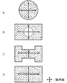
- FIG. 1 is a schematic schematic diagram showing the shape of the main surface of the deformed polarizing plate used in Examples 1 to 3 and Comparative Example 1.
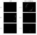
- FIG. 2 is a photograph showing the result of light leakage when the modified polarizing plate with the pressure-sensitive adhesive layer obtained in Example 1 was used.
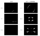
- FIG. 3 is a photograph showing the result of light leakage when the modified polarizing plate with the pressure-sensitive adhesive layer obtained in Comparative Example 1 was used.
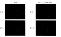
- FIG. 4 is a photograph showing a reference result of light leakage when the polarizing plate with an adhesive layer (not a variant) obtained in Example 1 and Comparative Example 1 is used.
- the deformed polarizing plate with an adhesive layer (hereinafter, also referred to as “the present polarizing plate”) according to the embodiment of the present invention is a deformed polarizing plate in which films (eg, protective film, retardation film) are provided on both sides of a polarizing element.
- a pressure-sensitive adhesive layer (hereinafter, also referred to as “the present pressure-sensitive adhesive layer”) satisfying the following requirements (I) or (II) is provided on at least one surface of the plate.
- the storage elastic modulus (G') of the pressure-sensitive adhesive layer at 80 ° C. is 2.0 ⁇ 10 4 to 1.0 ⁇ 10 5 Pa.
- this polarizing plate According to this polarizing plate, light leakage that may occur remarkably when a deformed polarizing plate having films provided on both sides of a polarizing element can be suppressed, particularly at a high temperature (eg, 80 ° C.) for a long time (eg, eg). The light leakage can be suppressed even after the lapse of 500 hours).
- a high temperature eg, 80 ° C.
- a long time eg, eg.
- the light leakage can be suppressed even after the lapse of 500 hours).
- the present inventor speculates that the reason for this is as follows. The following description is speculative and does not limit the present invention in any way.
- the deformed polarizing plate in one embodiment of the present invention is a polarizing plate having a main surface having a shape other than a square or a rectangle, and specifically, the shape of the main surface is an apex having an internal angle other than 90 °.
- the main surface of the modified polarizing plate is one or both of the surfaces having the largest area of the polarizing plate, and usually refers to a surface perpendicular to the direction in which light travels.
- the non-square and non-rectangular shapes include, for example, circles (including ellipses), triangles, squares and non-rectangular quadrangles (eg, diamonds, trapezoids), polygons of pentagons or more, and notches (recesses) in at least a part.
- circles including ellipses
- triangles squares and non-rectangular quadrangles
- polygons of pentagons or more and notches (recesses) in at least a part.
- a shape having a convex portion, a shape having a curved portion, and a shape having a hole portion (cut out) inside these shapes (including a square or a rectangle) can be mentioned.
- the following 1) to 3) can be considered.
- the direction of the principal stress generated in the polarizing plate is not perpendicular to or parallel to the polarization axis, but the optical axis of the photoelastic double refraction of the polarizing plate (particularly the film) generated by the stress. And, an angle is generated with the polarization axis of the polarizing plate, so that a phase difference derived from the polarizing plate is generated and light leakage occurs.
- the principal stress of the tangent line in the vicinity of the tangent line that is not perpendicular to or parallel to the polarization axis 2) 1) is the polarizing plate.
- the photoelastic birefringence of 1) above is determined by the magnitude of the stress generated in the polarizing plate. From the above, the deformed polarizing plate is more likely to cause light leakage than the polarizing plate having a square or rectangular main surface.
- the effect of the present invention is more likely to be exhibited particularly on the shape having a hole (extracted) inside such as (iii) and (iv) of the above 1).
- the shape of the main surface is a perfect circle, the effect of the present invention is difficult to be exhibited.
- the present polarizing plate may have the present pressure-sensitive adhesive layer on at least one surface of the modified polarizing plate, and may have the present pressure-sensitive adhesive layer on both surfaces of the modified polarizing plate.
- the pressure-sensitive adhesive layer is not particularly limited as long as it satisfies the following requirements (I) or (II), but it is preferable to satisfy the following requirements (I) and (II) from the viewpoint of more exerting the above effects.
- the storage elastic modulus (G') of the pressure-sensitive adhesive layer at 80 ° C. is 2.0 ⁇ 10 4 to 1.0 ⁇ 10 5 Pa.
- the storage elastic modulus (G') is 2. It is 0 ⁇ 10 4 Pa or more, preferably 2.5 ⁇ 10 4 Pa or more, 1.0 ⁇ 10 5 Pa or less, preferably 8.5 ⁇ 10 4 Pa or less, and more preferably 5.0. ⁇ 10 4 Pa or less.
- the storage elastic modulus of the present pressure-sensitive adhesive layer is within the above range, light leakage can be easily suppressed even after a long period of time (example: 500 hours) at a high temperature (example: 80 ° C.).
- the present polarizing plate having high reliability can be easily obtained because the interface with the polarizing plate is less likely to be lifted or peeled off.
- the storage elastic modulus (G') can be measured by the method described in the following Examples.
- the gel fraction of the present pressure-sensitive adhesive layer is 10 to 50% by mass.
- the gel fraction is 10% by mass or more, preferably 15% by mass or more, and 50% by mass or less. It is preferably 48% by mass or less, more preferably 45% by mass or less.
- the gel fraction of the present pressure-sensitive adhesive layer is within the above range, light leakage, particularly light leakage can be easily suppressed even after a long period of time (example: 500 hours) at a high temperature (example: 80 ° C.).
- the present polarizing plate having high reliability can be easily obtained because the interface with the polarizing plate is less likely to be lifted or peeled off.
- the gel fraction can be measured by the method described in the following Examples.
- the photoelastic modulus of the pressure-sensitive adhesive layer is preferably ⁇ 400 ⁇ 10 -12 m 2 / N or more, more preferably ⁇ 300 ⁇ 10 -12 m 2 / N or more, and preferably 400 ⁇ 10 -12 m 2 or more. / N or less, more preferably 300 ⁇ 10 -12 m 2 / N or less.
- the photoelastic coefficient of the pressure-sensitive adhesive layer is within the above range, the phase difference derived from the pressure-sensitive adhesive layer can be reduced, so that light leakage can be suppressed to a higher degree.
- the photoelastic modulus can be measured by the method described in the following Examples.
- the thickness of the pressure-sensitive adhesive layer is not particularly limited, but is usually 5 ⁇ m or more, preferably 10 ⁇ m or more, and usually 75 ⁇ m or less from the viewpoint that a pressure-sensitive adhesive layer having sufficient adhesiveness can be easily obtained. It is preferably 50 ⁇ m or less.
- the present pressure-sensitive adhesive layer is not particularly limited as long as it is a layer satisfying the above-mentioned requirements (I) or (II), but is a (meth) acrylic type from the viewpoint that the pressure-sensitive adhesive layer exhibiting the above-mentioned effect can be easily obtained. It is preferably a pressure-sensitive adhesive layer.
- the (meth) acrylic pressure-sensitive adhesive layer can be formed, for example, by using a pressure-sensitive adhesive composition containing a (meth) acrylic-based polymer.
- the pressure-sensitive adhesive composition may further contain a cross-linking agent, a silane coupling agent, and other components.
- the (meth) acrylic in the present invention refers to acrylic and / or methacrylic. Similar expressions have the same meaning.
- the (meth) acrylic polymer is preferably a (meth) acrylic acid alkyl ester (a-1) and / or an alkoxy group-containing (meth) acrylate (a-2), crosslinkable functional. It can be synthesized by copolymerizing a monomer component having a group (b) and, if necessary, a monomer component containing an aromatic ring-containing monomer (c) and other monomers (d).
- Examples of the (meth) acrylic acid alkyl ester (a-1) include methyl (meth) acrylate, ethyl (meth) acrylate, propyl (meth) acrylate, n-butyl (meth) acrylate, and iso-butyl (meth).
- the (meth) acrylic acid alkyl ester (a-1) is n-butyl acrylate, 2 from the viewpoint that a pressure-sensitive adhesive layer having a storage elastic modulus (G') in the above range can be easily formed.
- G' storage elastic modulus
- -Ethylhexyl acrylate is preferred.
- alkoxy group-containing (meth) acrylate (a-2) examples include alkoxy group-containing (meth) acrylates such as methoxyethyl (meth) acrylate, ethoxyethyl (meth) acrylate, and ethoxyethoxyethyl (meth) acrylate. Be done.
- the alkoxy group-containing (meth) acrylate (a-2) is a methoxyethyl (meth) acrylate from the viewpoint that a pressure-sensitive adhesive layer having a storage elastic modulus (G') in the above range can be easily formed. Is preferable.
- the (meth) acrylic acid alkyl ester (a-1) and / or the alkoxy group-containing (meth) acrylate (a-2) may be used alone or in combination of two or more.
- the amount of the (meth) acrylic acid alkyl ester (a-1) and the alkoxy group-containing (meth) acrylate (a-2) used is 100% by mass based on the total amount of the monomers for synthesizing the (meth) acrylic polymer. It is preferably 55% by mass or more, more preferably 60% by mass or more, preferably 98% by mass or less, and more preferably 95% by mass or less.
- Examples of the monomer (b) having a crosslinkable functional group include 2-hydroxyethyl (meth) acrylate, 4-hydroxybutyl (meth) acrylate, 2-hydroxypropyl (meth) acrylate, and 2-hydroxybutyl (meth).
- Hydroxyl-containing monomers such as acrylates, 6-hydroxyhexyl (meth) acrylates, 1,4-cyclohexanedimethanol mono (meth) acrylates, chloro-2-hydroxypropyl (meth) acrylates, and allyl alcohols; Acrylic acid, methacrylic acid, ⁇ -carboxyethyl (meth) acrylate, 5-carboxypentyl (meth) acrylate, mono (meth) succiloyloxyethyl ester, ⁇ -carboxypolycaprolactone mono (meth) acrylate, crotonic acid, maleic acid Examples thereof include carboxy group-containing monomers such as acid, fumaric acid, itaconic acid, and citraconic acid.
- the monomer (b) having a crosslinkable functional group one kind may be used, or two or more kinds may be used.
- the amount of the monomer (b) having a crosslinkable functional group is preferably 0.5% by mass or more, more preferably 1% by mass, based on 100% by mass of the total amount of the monomers in synthesizing the (meth) acrylic polymer. % Or more, preferably 10% by mass or less, and more preferably 8% by mass or less.
- Examples of the aromatic ring-containing monomer (c) include benzyl (meth) acrylate, phenyl (meth) acrylate, and phenoxyethyl (meth) acrylate.
- the aromatic ring-containing monomer (c) By using the aromatic ring-containing monomer (c), light leakage can be suppressed to a higher degree. Further, by using the aromatic ring-containing monomer (c), a pressure-sensitive adhesive layer having a photoelastic modulus in the above range can be easily obtained.
- the aromatic ring-containing monomer (c) may be used alone or in combination of two or more.
- the aromatic ring-containing monomer (c) is an optional component, but when the aromatic ring-containing monomer (c) is used, the amount used is 100% by mass in total of the monomers used for synthesizing the (meth) acrylic polymer. On the other hand, it is preferably 0.5% by mass or more, more preferably 1% by mass or more, preferably 30% by mass or less, and more preferably 25% by mass or less.
- Examples of the other monomer (d) include, for example.
- the other monomer (d) one type may be used, or two or more types may be used.
- the other monomer (d) is an optional component, but when the other monomer (d) is used, the amount used is 100% by mass of the total amount of the monomers for synthesizing the (meth) acrylic polymer. It is preferably 0.1% by mass or more, more preferably 0.5% by mass or more, preferably 15% by mass or less, and more preferably 10% by mass or less.
- the weight average molecular weight (Mw) of the (meth) acrylic polymer by gel permeation chromatography (GPC) is excellent in adhesive strength and durability, and facilitates an adhesive layer having excellent dimensional change and stress followability of the polarizing plate.
- Mw weight average molecular weight
- polystyrene conversion value it is preferably 500,000 or more, more preferably 600,000 or more, preferably 2 million or less, and more preferably 1.8 million or less.
- the content of the (meth) acrylic polymer is excellent in the balance of performance as an adhesive, and the solid content of the adhesive composition is particularly excellent in that an adhesive layer having excellent adhesive properties can be easily obtained. It is preferably 60 to 99.9% by mass, and more preferably 65 to 99.9% by mass with respect to 100% by mass.
- the (meth) acrylic polymer can be synthesized by copolymerizing the monomer components.
- a method for copolymerization for example, it can be produced by a conventionally known polymerization method such as a solution polymerization method, a bulk polymerization method, an emulsion polymerization method, and a suspension polymerization method, and among these, the solution polymerization method is preferable.
- a polymerization solvent and a monomer component are charged in a reaction vessel, a polymerization initiator is added under an atmosphere of an inert gas such as nitrogen gas, and the reaction initiation temperature is usually 40 ° C. or higher, preferably 50 ° C. or higher.
- the reaction system is usually set to 100 ° C. or lower, preferably 90 ° C. or lower, and the reaction system is maintained at a temperature of usually 50 to 90 ° C., preferably 60 to 90 ° C., and reacted for, for example, 3 to 20 hours (meth).
- Acrylic polymers can be synthesized.
- a polymerization initiator, a chain transfer agent, a polymerizable monomer, and a polymerization solvent may be additionally added during the polymerization reaction.
- polymerization initiator examples include peroxide-based polymerization initiators and azo-based initiators.
- the polymerization initiator may be used alone or in combination of two or more. Further, the polymerization initiator may be added a plurality of times during the polymerization.
- peroxide-based polymerization initiator examples include t-butyl hydroperoxide, cumene hydroperoxide, dicumyl peroxide, benzoyl peroxide, lauroyl peroxide, caproyl peroxide, and di-i-propylperoxy.
- azo-based initiator examples include 2,2'-azobisisobutyronitrile, 2,2'-azobis (4-methoxy-2,4-dimethylvaleronitrile), and 2,2'-azobis (2).
- -Cyclopropylpropionitrile 2,2'-azobis (2,4-dimethylvaleronitrile), 2,2'-azobis (2-methylbutyronitrile), 1,1'-azobis (cyclohexane-1-) Carbonitrile), 2- (carbamoylazo) isobutyronitrile, 2-phenylazo-4-methoxy-2,4-dimethylvaleronitrile, 2,2'-azobis (2-amidinopropane) dihydrochloride, 2,2' -Azobis (N, N'-dimethyleneisobutyramidin), 2,2'-azobis [2-methyl-N- (2-hydroxyethyl) -propionamide], 2,2'-azobis (isobutylamide) dihydrate,
- the polymerization initiator is usually 0.001 part by mass or more, preferably 0.005 part by mass or more, usually 5 parts by mass or less, preferably 3 parts by mass with respect to 100 parts by mass of the monomer component forming the (meth) acrylic polymer. It is used in an amount within the range of parts by mass or less.
- polymerization solvent examples include aromatic hydrocarbons such as benzene, toluene and xylene; aliphatic hydrocarbons such as n-pentane, n-hexane, n-heptane and n-octane; cyclopentane, cyclohexane and cyclo.
- Alicyclic hydrocarbons such as heptane and cyclooctane; ethers such as diethyl ether, diisopropyl ether, 1,2-dimethoxyethane, dibutyl ether, tetrahydrofuran, dioxane, anisole, phenylethyl ether and diphenyl ether; chloroform, carbon tetrachloride , 1,2-Dichloroethane, halogenated hydrocarbons such as chlorobenzene; esters such as methyl acetate, ethyl acetate, propyl acetate, butyl acetate, methyl propionate; acetone, methyl ethyl ketone, diethyl ketone, methyl isobutyl ketone, cyclohexanone, etc.
- ethers such as diethyl ether, diisopropyl ether, 1,2-dimethoxyethane, dibuty
- Ketones such as N, N-dimethylformamide, N, N-dimethylacetamide, N-methylpyrrolidone; nitriles such as acetonitrile and benzonitrile; sulfoxides such as dimethylsulfoxide and sulfolanes.
- One kind of polymerization solvent may be used, or two or more kinds may be used.
- the pressure-sensitive adhesive composition may optionally contain a crosslinking agent.
- a cross-linking agent is not particularly limited as long as it is a cross-linking agent capable of reacting with a (meth) acrylic polymer at room temperature or heating to form a cross-linked structure, and for example, an isocyanate-based cross-linking agent, an epoxy-based cross-linking agent, and the like. Examples thereof include a metal chelate-based cross-linking agent and an aziridine-based cross-linking agent. Of these, isocyanate-based cross-linking agents are particularly preferable. When the cross-linking agent is used, the cross-linking agent used may be one kind or two or more kinds.
- isocyanate-based cross-linking agent examples include isocyanate compounds such as xylylene diisocyanate, tolylene diisocyanate, chlorophenylenedi isocyanate, hexamethylene diisocyanate, tetramethylene diisocyanate, isophorone diisocyanate, diphenylmethane diisocyanate, xylene diisocyanate, and hydrogenated diphenylmethane diisocyanate.
- isocyanate group-containing reaction products obtained by reacting these isocyanate compounds with divalent or higher valent alcohols such as trimethylolpropane, and derivatives such as isocyanurates of these isocyanates.
- epoxy-based cross-linking agent examples include ethylene glycol diglycidyl ether, polyethylene glycol diglycidyl ether, glycerin diglycidyl ether, glycerin triglycidyl ether, 1,3-bis (N, N-diglycidyl aminomethyl) cyclohexane, and N.
- N, N', N'-tetraglycidyl-m-xylylene diamine N, N, N', N'-tetraglycidyl aminophenylmethane
- triglycidyl isocyanurate m-N, N-diglycidyl aminophenylglycidyl
- examples include ether, N, N-diglycidyl toluidine, and N, N-diglycidyl aniline.
- metal chelate-based cross-linking agent examples include polyvalent metals such as aluminum, iron, copper, zinc, tin, titanium, nickel, antimony, magnesium, vanadium, chromium, and zirconium, as well as alkoxide, acetylacetone, and ethyl acetoacetate. Coordinated compounds can be mentioned.
- the content of the cross-linking agent is preferably 0 with respect to 100 parts by mass of the (meth) acrylic polymer in the pressure-sensitive adhesive composition from the viewpoint of excellent balance of performance as a pressure-sensitive adhesive. 0.02 parts by mass or more, more preferably 0.03 parts by mass or more, further preferably 0.04 parts by mass or more, preferably 2 parts by mass or less, more preferably 1 part by mass or less, still more preferably 0.5 parts by mass. It is less than a part. Further, when the cross-linking agent is used in the above range, the pressure-sensitive adhesive layer having the storage elastic modulus and the gel fraction in the above range can be easily formed.
- the pressure-sensitive adhesive composition may optionally contain a silane coupling agent.
- a silane coupling agent is, for example, a polymerizable unsaturated group-containing silicon compound such as vinyltrimethoxysilane, vinyltriethoxysilane, and methacrypropyltrimethoxysilane; 3-glycidoxypropyltrimethoxysilane, 3-.
- Epoxy group-containing silicon compounds such as glycidoxypropylmethyldimethoxysilane, 2- (3,4-epoxycyclohexyl) ethyltrimethoxysilane; 3-aminopropyltrimethoxysilane, N- (2-aminoethyl) -3-amino Amino group-containing silicon compounds such as propyltrimethoxysilane, N- (2-aminoethyl) -3-aminopropylmethyldimethoxysilane; 3-chloropropyltrimethoxysilane; 3- (trimethoxysilyl) propyl 3-oxobutanoate; Examples thereof include oligomer-type silane coupling agents. When the silane coupling agent is used, the silane coupling agent used may be one type or two or more types.
- the content of the silane coupling agent is such that a pressure-sensitive adhesive layer having excellent adhesiveness can be easily obtained, and thus the (meth) acrylic polymer in the pressure-sensitive adhesive composition. It is preferably 0.05 parts by mass or more, more preferably 0.1 parts by mass or more, preferably 5 parts by mass or less, and more preferably 3 parts by mass or less with respect to 100 parts by mass.
- the pressure-sensitive adhesive composition may optionally contain other components as long as the effects of the present invention are not impaired.
- specific examples of such other components include antistatic agents, organic solvents, tackifying resins, adhesive strength reducing agents, antioxidants, ultraviolet absorbers, metal corrosion inhibitors, cross-linking accelerators, and plasticizers. , Organic particles, inorganic particles and the like. As the other components, one kind may be used for each, or two or more kinds may be used.
- the method for forming the pressure-sensitive adhesive layer is not particularly limited, and examples thereof include the following methods.
- the pressure-sensitive adhesive composition is applied onto the peeled substrate.
- the pressure-sensitive adhesive composition contains a solvent, it is usually 50 ° C. or higher, preferably 60 ° C. or higher, usually 150 ° C. or lower, preferably 100 ° C. or lower, usually 1 minute or longer, preferably 2 minutes or longer, usually. Is dried for 10 minutes or less, preferably 7 minutes or less to remove the solvent and form a coating film.
- another peeled base material or polarizing plate is attached to the surface of the coating film (adhesive layer) on the side where the peeled base material is not present.
- it is usually 1 day or more, preferably 3 to 10 days, usually 5 ° C or higher, preferably 15 ° C or higher, usually 60 ° C or lower, preferably 40 ° C or lower, usually 30 to 70% RH, preferably.
- It is cured in an environment of 40 to 70% RH to form an adhesive layer.
- the curing is also referred to as aging.
- the base material is not particularly limited, and examples thereof include base materials made of plastic, paper, metal, glass, and ceramics.
- the thickness of the base material is not particularly limited, but is usually 10 to 500 ⁇ m.
- plastic examples include polyethylene terephthalate (PET), polyvinyl chloride, polyolefin (polypropylene, polyethylene, TPO (olefin thermoplastic elastomer)), polymethylmethacrylate, polycarbonate, polyimide and ABS.
- PET polyethylene terephthalate
- polyvinyl chloride polyvinyl chloride
- polyolefin polypropylene
- polyethylene polyethylene
- TPO olefin thermoplastic elastomer
- polymethylmethacrylate polycarbonate
- polyimide polyimide
- Examples of the method for applying the pressure-sensitive adhesive composition include known methods such as spin coating method, knife coating method, roll coating method, bar coating method, blade coating method, die coating method, gravure coating method, and doctor blade method. Be done.
- ⁇ Deformed polarizing plate> As the deformed polarizing plate, a conventionally known polarizing plate having films provided on both sides of a polarizing element can be used, except that the shape of the main surface thereof is irregular. Further, the deformed polarizing plate may have other layers such as an antiglare layer, a retardation layer, and a viewing angle improving layer.
- the thickness of the modified polarizing plate is not particularly limited, but is usually 10 ⁇ m or more, preferably 15 ⁇ m or more, and usually 500 ⁇ m or less, preferably 300 ⁇ m or less.
- Examples of the polarizing element include a stretched film obtained by incorporating a polarizing component into a film made of a polyvinyl alcohol-based resin and stretching the film.
- Examples of the polyvinyl alcohol-based resin include saponified products of polyvinyl alcohol, polyvinylformal, polyvinyl acetal, and ethylene-vinyl acetate copolymer.
- Polarizing components include, for example, iodine and / or dichroic dyes.
- the thickness of the polarizing element is not particularly limited, but is usually 0.1 ⁇ m or more, preferably 1 ⁇ m or more, and usually 100 ⁇ m or less, preferably 50 ⁇ m or less.
- the film is not particularly limited, and examples thereof include a film conventionally used for a polarizing plate, and preferred examples thereof include a protective film (polarizer protective film) and a retardation film.
- the modified polarizing plate is not particularly limited as long as it has the film on both sides of the polarizing element, and may have, for example, two or more protective films, and may have two or more retardation films. It may also have one or more layers of protective film and one or more layers of retardation film.
- the protective film examples include a film made of a thermoplastic resin.
- the thermoplastic resin include cellulose resins such as triacetyl cellulose, polyester resins, polyether sulfone resins, polysulfone resins, polycarbonate resins, polyamide resins, polyimide resins, polyolefin resins, (meth) acrylic resins, and cyclic polyolefin resins (). Norbornen-based resins), polyarylate resins, polystyrene resins, polyvinyl alcohol resins, and mixtures of two or more selected from these resins.
- the thickness of the protective film is not particularly limited, but is usually 10 ⁇ m or more, preferably 20 ⁇ m or more, and usually 150 ⁇ m or less, preferably 130 ⁇ m or less.
- the retardation film is not particularly limited, and examples thereof include a resin film.
- the resin include polyester resin, polyether sulfone resin, polysulfone resin, polycarbonate resin, polyamide resin, polyimide resin, polyolefin resin, (meth) acrylic resin, cyclic polyolefin resin (norbornene resin), polyarylate resin, and polystyrene.
- resins include resins, polyvinyl alcohol resins, and mixtures of two or more selected from these resins.
- the thickness of the retardation film is not particularly limited, but is usually 10 ⁇ m or more, preferably 20 ⁇ m or more, and usually 150 ⁇ m or less, preferably 130 ⁇ m or less.
- the method for producing the present polarizing plate is not particularly limited, and examples thereof include the following methods.
- a laminate [peeling-treated base material / adhesive layer / peeling-treated base material] is formed by the same method as that described in the column of, and one of the peel-treated base materials is removed from the laminate.
- a method of attaching a polarizing plate to the peeled and exposed pressure-sensitive adhesive layer can be mentioned. Further, the present polarizing plate thus obtained may be processed into a desired shape, if necessary.
- Example 1 76.5 parts by mass of n-butyl acrylate (BA), 3 parts by mass of 2-hydroxyethyl acrylate (2HEA), acrylic acid (AA) in a reaction device equipped with a stirrer, a reflux cooler, a thermometer and a nitrogen introduction tube.
- a reaction device equipped with a stirrer, a reflux cooler, a thermometer and a nitrogen introduction tube.
- AA acrylic acid
- BzA benzyl acrylate
- BzA benzyl acrylate
- ethyl acetate solvent 0.5 part by mass of benzyl acrylate (BzA) and 100 parts by mass of ethyl acetate solvent were charged, and the temperature was raised to 70 ° C. while introducing nitrogen gas.
- 0.1 part by mass of 2,2'-azobisisobutyronitrile was added, and a polymerization reaction was carried out at 70 ° C. for 6 hours under a nitrogen gas atmosphere.
- the mixture was diluted with ethyl acetate to prepare a polymer solution 1 containing an acrylic polymer having a solid content concentration of 30% by mass.
- the weight average molecular weight (Mw) of the obtained acrylic polymer was 1.4 million.
- the Mw of the acrylic polymer was determined by gel permeation chromatography (GPC) method under the following conditions in terms of standard polystyrene.
- -Measuring device HLC-8120GPC (manufactured by Tosoh Corporation) ⁇ GPC column configuration: The following 5-column column (all manufactured by Tosoh Corporation) (1) TSK-GEL HXL-H (guard column) (2) TSK-GEL G7000HXL (3) TSK-GEL GMHXL (4) TSK-GEL GMHXL (5) TSK-GEL G2500HXL ⁇ Dilute with tetrahydrofuran so that the sample concentration is 1.0 mg / cm 3 ⁇ Mobile phase solvent: Tetrahydrofuran ⁇ Flow rate: 1.0 cm 3 / min -Column temperature: 40 ° C
- An isocyanate-based cross-linking agent (“TD-75” Soken Kagaku (“TD-75”) was applied to the obtained polymer solution 1 (solid content concentration 30% by mass) and 100 parts by mass (solid content amount) of the acrylic polymer contained in the polymer solution 1.
- a pressure-sensitive adhesive composition was obtained by mixing 0.045 parts by mass of a silane coupling agent (manufactured by "KBM-403" Shin-Etsu Chemical Industry Co., Ltd.) by 0.5 parts by mass.
- the obtained pressure-sensitive adhesive composition (after defoaming) is applied onto a stripped polyethylene terephthalate film (PET film) using a doctor blade, dried at 90 ° C. for 3 minutes, and dried to a dry film thickness. A 20 ⁇ m coating film was formed.
- the peeled PET film was further attached to the surface of the formed coating film opposite to the surface on which the PET film was attached, and allowed to stand for 7 days in a 23 ° C./50% RH environment for aging. By peeling the coating film from the PET film, an evaluation pressure-sensitive adhesive layer having a thickness of 20 ⁇ m was obtained.
- ⁇ Storage modulus> By laminating 50 of the obtained evaluation pressure-sensitive adhesive layers, a test piece for measuring the storage elastic modulus having a thickness of 1 mm was prepared. Using this test piece, the storage elastic modulus (G') at 80 ° C. was measured using a modular compact reometer MCR300 manufactured by AntonioPaar. The measurement frequency was 1 Hz. The storage elastic modulus (G') of the evaluation pressure-sensitive adhesive layer obtained in Example 1 was 3.0 ⁇ 10 4 Pa.
- ⁇ Photoelastic coefficient> The obtained 50 evaluation pressure-sensitive adhesive layers were bonded together in a 23 ° C./50% RH environment and treated in an autoclave adjusted to 50 ° C./5 atm for 20 minutes to measure a photoelastic modulus with a thickness of 1.0 mm.
- a test piece was prepared. The obtained test piece is cut into a size of 15 mm ⁇ 50 mm, and this is attached to an automatic wavelength scanning ellipsometer (model “M-220”, manufactured by JASCO Corporation) using a jig to change the stress. The retardation (measurement wavelength: 633 nm) was measured while allowing the measurement.
- the slope of a straight line when stress is on the horizontal axis and retardation is on the vertical axis is used as the photoelastic modulus of the pressure-sensitive adhesive layer for evaluation.
- the photoelastic modulus of the evaluation pressure-sensitive adhesive layer obtained in Example 1 was -50 ⁇ 10 -12 m 2 / N.
- the obtained pressure-sensitive adhesive composition (after defoaming) is applied onto a stripped polyethylene terephthalate film (PET film) using a doctor blade, dried at 90 ° C. for 3 minutes, and dried to a dry film thickness.
- a sheet having a coating film of 20 ⁇ m was obtained.
- the obtained sheet has a triacetyl cellulose film (protective film) on both sides of a polyvinyl alcohol film as a polarizing element, and a polarizing plate (thickness 60 ⁇ m) having a circular main surface (shape shown in FIG. 1A).
- the sheet is bonded to one side of the sheet so that the coating surface and the protective film surface are in contact with each other, and allowed to stand for 7 days at 23 ° C./50% RH for aging.
- a polarizing plate with an adhesive layer having a plate was obtained.
- Two polarizing plates with an adhesive layer were prepared, and the PET films were peeled off from the two obtained polarizing plates with an adhesive, respectively, and then using a laminator roll, both sides of an alkaline glass plate having a thickness of 0.5 mm were used.
- Light leakage is achieved by attaching the polarizing plate so that the polarization axes of the polarizing plates are orthogonal to each other and the adhesive layer and the alkali glass plate are in contact with each other, and holding the polarizing plate in an autoclave adjusted to 50 ° C./5 atm for 20 minutes. A test laminate was obtained.
- the obtained light leakage test laminate was irradiated with the light of the backlight of the liquid crystal monitor, the state of the light leakage at that time was photographed with a luminance meter, and the state of the light leakage was observed (initial light leakage).
- the result of this initial light leakage is shown in A-1 of FIG.
- the state of light leakage after 80 ° C. ⁇ 500 hours was similarly observed except that the obtained laminated body for light leakage test was left for 500 hours under the condition of a temperature of 80 ° C./dry for 500 hours. confirmed.
- the result of the light leakage after 80 ° C. ⁇ 500 hours is shown in A-2 of FIG.
- a polarizing plate having a circular main surface shape (shape shown in FIG. 1A)
- a polarizing plate having a main surface shape having a hole (cut out) (shape shown in FIG. 1B) was used.
- the state of light leakage at the initial stage and after 80 ° C. ⁇ 500 hours was observed.
- B-1 and B-2 of FIG. 2 respectively.
- a polarizing plate having a circular main surface shape shape shown in FIG. 1A
- a polarizing plate having a main surface shape having a notch (recess) (shape shown in FIG. 1C) was used.
- C-1 and C-2 of FIG. 2 respectively.
- the results of the light leakage test were visually judged according to the following criteria. Good: No light leakage was confirmed or a slight light leakage was confirmed after 80 ° C. ⁇ 500 hours, but there was no problem in actual use. Possible: Light leakage was confirmed after 80 ° C x 500 hours, but there was no problem in actual use. Impossible: Clear light leakage was confirmed after 80 ° C. ⁇ 500 hours.
- the results of the light leakage test in Table 1 are shown by the following criteria by integrating the results when the light leakage of each of the polarizing plates having the shapes shown in FIGS. 1A to 1C is evaluated according to the above criteria.
- ⁇ All three polarizing plates used were evaluated as “good”.
- ⁇ Of the three polarizing plates used, none of them was evaluated as “impossible”, but there was one or more evaluations of “possible”.
- X Even one of the three polarizing plates used was evaluated as "impossible”.
- Examples 2 to 3, Comparative Example 1 The same procedure as in Example 1 was carried out except that an acrylic polymer was synthesized using the monomer components shown in Table 1 and a pressure-sensitive adhesive composition was obtained using the cross-linking agent shown in Table 1, and the pressure-sensitive adhesive layer for evaluation was obtained. And a polarizing plate with an adhesive layer was obtained. The same evaluation as in Example 1 was performed using the obtained evaluation pressure-sensitive adhesive layer and the polarizing plate with the pressure-sensitive adhesive layer. The results are shown in Table 1.
- "L-45" in Table 1 is an isocyanate-based cross-linking agent manufactured by Soken Chemical Co., Ltd.
- FIG. 3 shows the light leakage of the polarizing plate with the pressure-sensitive adhesive layer obtained in Comparative Example 1, and shows the initial stage and the case where the polarizing plate having a circular main surface (shape shown in FIG. 1A) is used.
- the state of light leakage after 80 ° C. ⁇ 500 hours is shown in A-1 and A-2 of FIG. 3, respectively, and the shape of the main surface is a shape having a hole (cut out) (shape shown in FIG. 1B).
- the state of light leakage at the initial stage and after 80 ° C. ⁇ 500 hours when a plate is used is shown in B-1 and B-2 of FIG. 3, respectively, and the shape of the main surface has a notch (recess) (FIG. 1C).
- the state of light leakage at the initial stage and after 80 ° C. ⁇ 500 hours when the polarizing plate having the shape shown in FIG. 3) is used is shown in C-1 and C-2 of FIG. 3, respectively.
- Example 1 and Comparative Example 1 the state of light leakage at the initial stage and after 80 ° C. ⁇ 500 hours when a polarizing plate having a rectangular shape (shape shown in FIG. 1D) is used is the same as described above. I observed it.
- the state of light leakage at the initial stage and after 80 ° C. ⁇ 500 hours when the pressure-sensitive adhesive layer obtained in Example 1 is used is shown in D-1 and D-2 of FIG. 4, respectively.
- the state of light leakage at the initial stage and after 80 ° C. ⁇ 500 hours when the pressure-sensitive adhesive layer obtained in Comparative Example 1 is used is shown in D'-1 and D'-2 of FIG. 4, respectively.
- the present invention is an invention specialized for a deformed polarizing plate in that light leakage, which is particularly likely to occur in a deformed polarizing plate, can be suppressed.
Landscapes
- Physics & Mathematics (AREA)
- Chemical & Material Sciences (AREA)
- Optics & Photonics (AREA)
- Organic Chemistry (AREA)
- Nonlinear Science (AREA)
- General Physics & Mathematics (AREA)
- Crystallography & Structural Chemistry (AREA)
- Mathematical Physics (AREA)
- Engineering & Computer Science (AREA)
- Mechanical Engineering (AREA)
- Polarising Elements (AREA)
- Adhesives Or Adhesive Processes (AREA)
- Adhesive Tapes (AREA)
Abstract
偏光子の両面にフィルムが設けられた異形偏光板の少なくとも一方の面に粘着剤層を有し、前記異形偏光板が、その主面の形状が正方形および長方形以外の形状の偏光板であり、前記粘着剤層が、下記要件(I)または(II)を満たす、粘着剤層付き異形偏光板。 要件(I):前記粘着剤層の80℃における貯蔵弾性率(G')が、2.0×10⁴~1.0×10⁵Paである 要件(II):前記粘着剤層のゲル分率が10~50質量%である
Description
本発明の一実施形態は、粘着剤層付き異形偏光板に関する。
液晶表示装置(LCD)は、薄型、軽量でかつ消費電力が小さいことから、テレビ、ノートパソコン、モニター、スマートフォン等に広く用いられている。液晶表示装置は、液晶セルの両側に粘着剤で偏光板を貼合した液晶パネル部材を有し、バックライト部材からの光を液晶パネル部材で制御することにより表示が行われている。
LCDは、その主面の形状が長方形であることが一般的であるが、近年、スマートフォンや車載モニター等に使用されるLCDには、長方形や正方形以外の形状(異形)の表示装置が採用される場合があり、この場合には、粘着剤層付き異形偏光板が用いられている。
このような粘着剤層付き異形偏光板として、例えば特許文献1には、偏光板の粘着剤層が形成される面において、粘着剤層と接触しない非接触部が偏光板端部に形成されていることを特徴とする粘着剤層付き偏光板が開示されている。
前記偏光板としては、その力学的性質および光学的耐久性を向上させるため、一般的に、偏光機能を有する偏光子の一方の面または両面に、トリアセチルセルロースフィルム等の偏光子保護フィルムが積層された構造が採用されている。また、外光反射等の問題を抑制するために、偏光子位相差フィルムが積層された構造が採用されることもある。
これら偏光板を構成する各材料(各層)はそれぞれ異なる物理・化学的特性を有しているため、温度や湿度の影響による収縮や膨潤の寸法変化の度合いや、各材料に生じる応力がそれぞれ異なるが、従来の主面の形状が長方形や正方形である偏光板では、この寸法変化や応力に伴う問題がそれほど大きいものではなかった。
これら偏光板を構成する各材料(各層)はそれぞれ異なる物理・化学的特性を有しているため、温度や湿度の影響による収縮や膨潤の寸法変化の度合いや、各材料に生じる応力がそれぞれ異なるが、従来の主面の形状が長方形や正方形である偏光板では、この寸法変化や応力に伴う問題がそれほど大きいものではなかった。
一方で、近年使用されている偏光子の両面にフィルムが設けられた異形偏光板では、前記寸法変化や応力に伴い、光漏れが顕著に生じることが分かった。
しかしながら、前記従来の粘着剤層付き偏光板では、このような光漏れを十分に抑制することはできず、この点で改良の余地があった。
しかしながら、前記従来の粘着剤層付き偏光板では、このような光漏れを十分に抑制することはできず、この点で改良の余地があった。
本発明の一実施形態は、偏光子の両面にフィルムが設けられた異形偏光板を用いる場合に顕著に生じ得る光漏れを抑制できる、特に、高温下で長時間経過後であっても該光漏れを抑制できる粘着剤層付き異形偏光板を提供する。
本発明者らは、前記課題を解決する方法について鋭意検討を重ねた結果、下記構成例によれば前記課題を解決できることを見出し、本発明を完成するに至った。本発明の構成例は以下の通りである。
なお、本明細書では、「偏光板」は「偏光フィルム」を包含する意味で用い、本明細書において、板、フィルム、シート等に特に区別はない。
なお、本明細書では、「偏光板」は「偏光フィルム」を包含する意味で用い、本明細書において、板、フィルム、シート等に特に区別はない。
[1] 偏光子の両面にフィルムが設けられた異形偏光板の少なくとも一方の面に粘着剤層を有し、
前記異形偏光板が、その主面の形状が正方形および長方形以外の形状の偏光板であり、
前記粘着剤層が、下記要件(I)または(II)を満たす、
粘着剤層付き異形偏光板。
要件(I):前記粘着剤層の80℃における貯蔵弾性率(G')が、2.0×10⁴~1.0×10⁵Paである
要件(II):前記粘着剤層のゲル分率が10~50質量%である
前記異形偏光板が、その主面の形状が正方形および長方形以外の形状の偏光板であり、
前記粘着剤層が、下記要件(I)または(II)を満たす、
粘着剤層付き異形偏光板。
要件(I):前記粘着剤層の80℃における貯蔵弾性率(G')が、2.0×10⁴~1.0×10⁵Paである
要件(II):前記粘着剤層のゲル分率が10~50質量%である
[2] 前記粘着剤層の光弾性係数が-400×10-12~400×10-12m2/Nである、[1]に記載の粘着剤層付き異形偏光板。
本発明の一実施形態によれば、偏光子の両面にフィルムが設けられた異形偏光板を用いる場合に顕著に生じ得る光漏れを抑制できる、特に、高温(例:80℃)下で長時間(例:500時間)経過後であっても該光漏れを抑制できる粘着剤層付き偏光板を提供することができる。
また、本発明の一実施形態によれば、偏光板に生じ得る寸法変化や反りを抑制することができ、長期にわたる信頼性(耐久性)に優れる粘着剤層付き異形偏光板を提供することができる。
また、本発明の一実施形態によれば、偏光板に生じ得る寸法変化や反りを抑制することができ、長期にわたる信頼性(耐久性)に優れる粘着剤層付き異形偏光板を提供することができる。
≪粘着剤層付き異形偏光板≫
本発明の一実施形態に係る粘着剤層付き異形偏光板(以下「本偏光板」ともいう。)は、偏光子の両面にフィルム(例:保護フィルム、位相差フィルム)が設けられた異形偏光板の少なくとも一方の面に、下記要件(I)または(II)を満たす粘着剤層(以下「本粘着剤層」ともいう。)を有する。
要件(I):本粘着剤層の80℃における貯蔵弾性率(G')は、2.0×10⁴~1.0×10⁵Paである
要件(II):本粘着剤層のゲル分率は10~50質量%である
本発明の一実施形態に係る粘着剤層付き異形偏光板(以下「本偏光板」ともいう。)は、偏光子の両面にフィルム(例:保護フィルム、位相差フィルム)が設けられた異形偏光板の少なくとも一方の面に、下記要件(I)または(II)を満たす粘着剤層(以下「本粘着剤層」ともいう。)を有する。
要件(I):本粘着剤層の80℃における貯蔵弾性率(G')は、2.0×10⁴~1.0×10⁵Paである
要件(II):本粘着剤層のゲル分率は10~50質量%である
本偏光板によれば、偏光子の両面にフィルムが設けられた異形偏光板を用いる場合に顕著に生じ得る光漏れを抑制できる、特に、高温(例:80℃)下で長時間(例:500時間)経過後であっても該光漏れを抑制できる。本発明者は、この理由を以下のように推測している。なお、以下の説明は推測であって、本発明を何ら限定するものではない。
本発明の一実施形態における異形偏光板は、その主面の形状が正方形および長方形以外の形状の偏光板であり、具体的には、その主面の形状が、内角が90°以外の頂点(凹頂点を含む)を有する多角形、円形、一部に曲線を有する形状、または、これらの形状(正方形や長方形を含む)の内部に穴部(抜き)を有する形状の偏光板である。
前記異形偏光板の主面とは、該偏光板の面積の最も大きい面の一方または両方であり、通常、光が進む方向に対し垂直な面のことをいう。
前記異形偏光板の主面とは、該偏光板の面積の最も大きい面の一方または両方であり、通常、光が進む方向に対し垂直な面のことをいう。
前記正方形および長方形以外の形状とは、例えば、円形(楕円等も含む)、三角形、正方形および長方形以外の四角形(例:ひし形、台形)、五角形以上の多角形、少なくとも一部にノッチ(凹部)や凸部を有する形状、曲線を有する形状、これらの形状(正方形や長方形を含む)の内部に穴部(抜き)を有する形状が挙げられる。
このような異形偏光板では、以下の1)~3)が考えられる。
1)以下の(i)~(iv)では、該偏光板に生じる主応力の方向が偏光軸と垂直または並行ではなく、応力によって生じる偏光板(特に前記フィルム)の光弾性複屈折の光学軸と、偏光板の偏光軸とに角度が生じることで偏光板由来の位相差が生じ、光漏れが生じる。
(i)頂点を有する三角形、四角形、および多角形の場合、その頂点付近
(ii)円形または一部に曲線を有する形状の場合、その接線のうち、偏光軸と垂直または並行ではない接線付近
(iii)内部に穴部(抜き)を有する形状の場合であって、その穴部が頂点を有する三角形、四角形、および多角形の場合、その頂点付近
(iv)内部に穴部(抜き)を有する形状の場合であって、その穴部が円形または一部に曲線を有する形状の場合、その接線のうち、偏光軸と垂直または並行ではない接線付近
2)前記1)の主応力は、偏光板の幾何中心に近い程大きいため、前記(i)~(iv)の場所が、偏光板の幾何中心に近いほど光漏れ量が多い。
3)前記1)の光弾性複屈折は偏光板に生じる応力の大きさによって決まる。
以上のことから、異形偏光板は、主面の形状が正方形や長方形の偏光板よりも光漏れを生じやすい。また、前記2)より、前記1)の(iii)および(iv)のような内部に穴部(抜き)を有する形状に対して、特に本発明の効果がより発揮されやすい。逆に、主面の形状が真円の場合は本発明の効果が発揮されにくい。
1)以下の(i)~(iv)では、該偏光板に生じる主応力の方向が偏光軸と垂直または並行ではなく、応力によって生じる偏光板(特に前記フィルム)の光弾性複屈折の光学軸と、偏光板の偏光軸とに角度が生じることで偏光板由来の位相差が生じ、光漏れが生じる。
(i)頂点を有する三角形、四角形、および多角形の場合、その頂点付近
(ii)円形または一部に曲線を有する形状の場合、その接線のうち、偏光軸と垂直または並行ではない接線付近
(iii)内部に穴部(抜き)を有する形状の場合であって、その穴部が頂点を有する三角形、四角形、および多角形の場合、その頂点付近
(iv)内部に穴部(抜き)を有する形状の場合であって、その穴部が円形または一部に曲線を有する形状の場合、その接線のうち、偏光軸と垂直または並行ではない接線付近
2)前記1)の主応力は、偏光板の幾何中心に近い程大きいため、前記(i)~(iv)の場所が、偏光板の幾何中心に近いほど光漏れ量が多い。
3)前記1)の光弾性複屈折は偏光板に生じる応力の大きさによって決まる。
以上のことから、異形偏光板は、主面の形状が正方形や長方形の偏光板よりも光漏れを生じやすい。また、前記2)より、前記1)の(iii)および(iv)のような内部に穴部(抜き)を有する形状に対して、特に本発明の効果がより発揮されやすい。逆に、主面の形状が真円の場合は本発明の効果が発揮されにくい。
以上のことから、異形偏光板を用いる場合に生じる光漏れを抑制するためには、(A)偏光板の光弾性係数の低減と、(B)前記1)部分における偏光板の応力の低減とが有効であると推測されるが、これらの中でも、異形偏光板では特に(B)が重要になると推測される。
そして、本偏光板によれば、異形偏光板の少なくとも一方の面に前記本粘着剤層を有するため、異形偏光板(特に前記フィルム)に生じる応力を緩和することで前記(B)に係る前記1)に記載の箇所における偏光板の応力を低減でき、異形偏光板を用いる場合に生じる光漏れを抑制できると推測される。
そして、本偏光板によれば、異形偏光板の少なくとも一方の面に前記本粘着剤層を有するため、異形偏光板(特に前記フィルム)に生じる応力を緩和することで前記(B)に係る前記1)に記載の箇所における偏光板の応力を低減でき、異形偏光板を用いる場合に生じる光漏れを抑制できると推測される。
[粘着剤層]
本偏光板は、異形偏光板の少なくとも一方の面に本粘着剤層を有していればよく、異形偏光板の両面に本粘着剤層を有していてもよい。
本粘着剤層は、下記要件(I)または(II)を満たせば特に制限されないが、前記効果がより発揮される等の点から、下記要件(I)および(II)を満たすことが好ましい。
下記要件(I)または(II)を満たす粘着剤層を用いることで、偏光板に生じ得る寸法変化や応力を緩和することができるため、前記効果を奏すると考えられる。
本偏光板は、異形偏光板の少なくとも一方の面に本粘着剤層を有していればよく、異形偏光板の両面に本粘着剤層を有していてもよい。
本粘着剤層は、下記要件(I)または(II)を満たせば特に制限されないが、前記効果がより発揮される等の点から、下記要件(I)および(II)を満たすことが好ましい。
下記要件(I)または(II)を満たす粘着剤層を用いることで、偏光板に生じ得る寸法変化や応力を緩和することができるため、前記効果を奏すると考えられる。
要件(I):本粘着剤層の80℃における貯蔵弾性率(G')は、2.0×10⁴~1.0×10⁵Paである
前記貯蔵弾性率(G')は、2.0×10⁴Pa以上であり、好ましくは2.5×10⁴Pa以上であり、1.0×10⁵Pa以下であり、好ましくは8.5×10⁴Pa以下、より好ましくは5.0×10⁴Pa以下である。
本粘着剤層の貯蔵弾性率が前記範囲にあると、光漏れ、特に、高温(例:80℃)下で長時間(例:500時間)経過後であっても光漏れを容易に抑制でき、さらに、偏光板との界面に浮きや剥がれが生じ難く、信頼性の高い本偏光板を容易に得ることができる。
前記貯蔵弾性率(G')は、具体的には下記実施例に記載の方法で測定できる。
前記貯蔵弾性率(G')は、2.0×10⁴Pa以上であり、好ましくは2.5×10⁴Pa以上であり、1.0×10⁵Pa以下であり、好ましくは8.5×10⁴Pa以下、より好ましくは5.0×10⁴Pa以下である。
本粘着剤層の貯蔵弾性率が前記範囲にあると、光漏れ、特に、高温(例:80℃)下で長時間(例:500時間)経過後であっても光漏れを容易に抑制でき、さらに、偏光板との界面に浮きや剥がれが生じ難く、信頼性の高い本偏光板を容易に得ることができる。
前記貯蔵弾性率(G')は、具体的には下記実施例に記載の方法で測定できる。
要件(II):本粘着剤層のゲル分率が10~50質量%である
前記ゲル分率は、10質量%以上であり、好ましくは15質量%以上であり、50質量%以下であり、好ましくは48質量%以下、より好ましくは45質量%以下である。
本粘着剤層のゲル分率が前記範囲にあると、光漏れ、特に、高温(例:80℃)下で長時間(例:500時間)経過後であっても光漏れを容易に抑制でき、さらに、偏光板との界面に浮きや剥がれが生じ難く、信頼性の高い本偏光板を容易に得ることができる。
前記ゲル分率は、具体的には下記実施例に記載の方法で測定できる。
前記ゲル分率は、10質量%以上であり、好ましくは15質量%以上であり、50質量%以下であり、好ましくは48質量%以下、より好ましくは45質量%以下である。
本粘着剤層のゲル分率が前記範囲にあると、光漏れ、特に、高温(例:80℃)下で長時間(例:500時間)経過後であっても光漏れを容易に抑制でき、さらに、偏光板との界面に浮きや剥がれが生じ難く、信頼性の高い本偏光板を容易に得ることができる。
前記ゲル分率は、具体的には下記実施例に記載の方法で測定できる。
本粘着剤層の光弾性係数は、好ましくは-400×10-12m2/N以上、より好ましくは-300×10-12m2/N以上であり、好ましくは400×10-12m2/N以下、より好ましくは300×10-12m2/N以下である。
本粘着剤層の光弾性係数が前記範囲にあると、粘着剤層由来の位相差を低減できるため、より高度に光漏れを抑制できる。
前記光弾性係数は、具体的には下記実施例に記載の方法で測定できる。
本粘着剤層の光弾性係数が前記範囲にあると、粘着剤層由来の位相差を低減できるため、より高度に光漏れを抑制できる。
前記光弾性係数は、具体的には下記実施例に記載の方法で測定できる。
本粘着剤層の厚さは特に制限されないが、粘着性を十分に有する粘着剤層を容易に得ることができる等の点から、通常は5μm以上、好ましくは10μm以上であり、通常は75μm以下、好ましくは50μm以下である。
〈粘着剤組成物〉
本粘着剤層は、前記要件(I)または(II)を満たす層であれば特に制限されないが、前記効果を奏する粘着剤層を容易に得ることができる等の点から、(メタ)アクリル系粘着剤層であることが好ましい。
前記(メタ)アクリル系粘着剤層は、例えば、(メタ)アクリル系ポリマーを含む粘着剤組成物を用いて形成することができる。該粘着剤組成物は、さらに、架橋剤、シランカップリング剤、およびその他の成分を含んでいてもよい。
なお、本発明における(メタ)アクリルは、アクリルおよび/またはメタクリルのことをいう。同様の表現は同様の意味である。
本粘着剤層は、前記要件(I)または(II)を満たす層であれば特に制限されないが、前記効果を奏する粘着剤層を容易に得ることができる等の点から、(メタ)アクリル系粘着剤層であることが好ましい。
前記(メタ)アクリル系粘着剤層は、例えば、(メタ)アクリル系ポリマーを含む粘着剤組成物を用いて形成することができる。該粘着剤組成物は、さらに、架橋剤、シランカップリング剤、およびその他の成分を含んでいてもよい。
なお、本発明における(メタ)アクリルは、アクリルおよび/またはメタクリルのことをいう。同様の表現は同様の意味である。
・(メタ)アクリル系ポリマー
前記(メタ)アクリル系ポリマーは、好ましくは、(メタ)アクリル酸アルキルエステル(a-1)および/またはアルコキシ基含有(メタ)アクリレート(a-2)、架橋性官能基を有するモノマー(b)、ならびに、必要により、芳香環含有モノマー(c)およびこれら以外のその他のモノマー(d)を含むモノマー成分を共重合することで合成することができる。
前記(メタ)アクリル系ポリマーは、好ましくは、(メタ)アクリル酸アルキルエステル(a-1)および/またはアルコキシ基含有(メタ)アクリレート(a-2)、架橋性官能基を有するモノマー(b)、ならびに、必要により、芳香環含有モノマー(c)およびこれら以外のその他のモノマー(d)を含むモノマー成分を共重合することで合成することができる。
前記(メタ)アクリル酸アルキルエステル(a-1)としては、例えば、メチル(メタ)アクリレート、エチル(メタ)アクリレート、プロピル(メタ)アクリレート、n-ブチル(メタ)アクリレート、iso-ブチル(メタ)アクリレート、t-ブチル(メタ)アクリレート、ペンチル(メタ)アクリレート、ヘキシル(メタ)アクリレート、ヘプチル(メタ)アクリレート、2-エチルヘキシル(メタ)アクリレート、n-オクチル(メタ)アクリレート、iso-オクチル(メタ)アクリレート、n-ノニル(メタ)アクリレート、iso-ノニル(メタ)アクリレート、n-デシル(メタ)アクリレート、iso-デシル(メタ)アクリレート、ラウリル(メタ)アクリレート、ステアリル(メタ)アクリレート、iso-ステアリル(メタ)アクリレートが挙げられる。
前記(メタ)アクリル酸アルキルエステル(a-1)としては、貯蔵弾性率(G')が前記範囲にある粘着剤層を容易に形成することができる等の点から、n-ブチルアクリレート、2-エチルヘキシルアクリレートが好ましい。
前記(メタ)アクリル酸アルキルエステル(a-1)としては、貯蔵弾性率(G')が前記範囲にある粘着剤層を容易に形成することができる等の点から、n-ブチルアクリレート、2-エチルヘキシルアクリレートが好ましい。
前記アルコキシ基含有(メタ)アクリレート(a-2)としては、例えば、メトキシエチル(メタ)アクリレート、エトキシエチル(メタ)アクリレート、エトキシエトキシエチル(メタ)アクリレート等のアルコキシ基含有(メタ)アクリレートが挙げられる。
前記アルコキシ基含有(メタ)アクリレート(a-2)としては、貯蔵弾性率(G')が前記範囲にある粘着剤層を容易に形成することができる等の点から、メトキシエチル(メタ)アクリレートが好ましい。
前記アルコキシ基含有(メタ)アクリレート(a-2)としては、貯蔵弾性率(G')が前記範囲にある粘着剤層を容易に形成することができる等の点から、メトキシエチル(メタ)アクリレートが好ましい。
前記(メタ)アクリル酸アルキルエステル(a-1)および/またはアルコキシ基含有(メタ)アクリレート(a-2)は、1種を用いてもよく、2種以上を用いてもよい。
前記(メタ)アクリル酸アルキルエステル(a-1)およびアルコキシ基含有(メタ)アクリレート(a-2)の使用量は、(メタ)アクリル系ポリマーを合成する際のモノマーの合計100質量%に対し、好ましくは55質量%以上、より好ましくは60質量%以上であり、好ましくは98質量%以下、より好ましくは95質量%以下である。
前記(メタ)アクリル酸アルキルエステル(a-1)およびアルコキシ基含有(メタ)アクリレート(a-2)の使用量は、(メタ)アクリル系ポリマーを合成する際のモノマーの合計100質量%に対し、好ましくは55質量%以上、より好ましくは60質量%以上であり、好ましくは98質量%以下、より好ましくは95質量%以下である。
前記架橋性官能基を有するモノマー(b)としては、例えば、2-ヒドロキシエチル(メタ)アクリレート、4-ヒドロキシブチル(メタ)アクリレート、2-ヒドロキシプロピル(メタ)アクリレート、2-ヒドロキシブチル(メタ)アクリレート、6-ヒドロキシヘキシル(メタ)アクリレート、1,4-シクロヘキサンジメタノールモノ(メタ)アクリレート、クロロ-2-ヒドロキシプロピル(メタ)アクリレート、アリルアルコール等の水酸基含有モノマー;
アクリル酸、メタクリル酸、β-カルボキシエチル(メタ)アクリレート、5-カルボキシペンチル(メタ)アクリレート、コハク酸モノ(メタ)アクリロイルオキシエチルエステル、ω-カルボキシポリカプロラクトンモノ(メタ)アクリレート、クロトン酸、マレイン酸、フマル酸、イタコン酸、シトラコン酸等のカルボキシ基含有モノマーが挙げられる。
アクリル酸、メタクリル酸、β-カルボキシエチル(メタ)アクリレート、5-カルボキシペンチル(メタ)アクリレート、コハク酸モノ(メタ)アクリロイルオキシエチルエステル、ω-カルボキシポリカプロラクトンモノ(メタ)アクリレート、クロトン酸、マレイン酸、フマル酸、イタコン酸、シトラコン酸等のカルボキシ基含有モノマーが挙げられる。
前記架橋性官能基を有するモノマー(b)は、1種を用いてもよく、2種以上を用いてもよい。
前記架橋性官能基を有するモノマー(b)の使用量は、(メタ)アクリル系ポリマーを合成する際のモノマーの合計100質量%に対し、好ましくは0.5質量%以上、より好ましくは1質量%以上であり、好ましくは10質量%以下、より好ましくは8質量%以下である。
前記架橋性官能基を有するモノマー(b)の使用量は、(メタ)アクリル系ポリマーを合成する際のモノマーの合計100質量%に対し、好ましくは0.5質量%以上、より好ましくは1質量%以上であり、好ましくは10質量%以下、より好ましくは8質量%以下である。
前記芳香環含有モノマー(c)としては、例えば、ベンジル(メタ)アクリレート、フェニル(メタ)アクリレート、フェノキシエチル(メタ)アクリレートが挙げられる。
前記芳香環含有モノマー(c)を使用することで、より高度に光漏れを抑制することができる。また、芳香環含有モノマー(c)を使用することで、光弾性係数が前記範囲にある粘着剤層を容易に得ることができる。
前記芳香環含有モノマー(c)を使用することで、より高度に光漏れを抑制することができる。また、芳香環含有モノマー(c)を使用することで、光弾性係数が前記範囲にある粘着剤層を容易に得ることができる。
前記芳香環含有モノマー(c)は、1種を用いてもよく、2種以上を用いてもよい。
前記芳香環含有モノマー(c)は任意成分であるが、該芳香環含有モノマー(c)を使用する場合、その使用量は、(メタ)アクリル系ポリマーを合成する際のモノマーの合計100質量%に対し、好ましくは0.5質量%以上、より好ましくは1質量%以上であり、好ましくは30質量%以下、より好ましくは25質量%以下である。
前記芳香環含有モノマー(c)は任意成分であるが、該芳香環含有モノマー(c)を使用する場合、その使用量は、(メタ)アクリル系ポリマーを合成する際のモノマーの合計100質量%に対し、好ましくは0.5質量%以上、より好ましくは1質量%以上であり、好ましくは30質量%以下、より好ましくは25質量%以下である。
前記その他のモノマー(d)としては、例えば、
(メタ)アクリルアミド、N,N-ジメチル(メタ)アクリルアミド、N-イソプロピル(メタ)アクリルアミド、N,N-ジエチル(メタ)アクリルアミド、(メタ)アクリロイルモルホリン、N-ビニルアセトアミド、ダイアセトン(メタ)アクリルアミド、N,N-ジメチルアミノプロピル(メタ)アクリルアミド、N,N-ジエチルアミノエチル(メタ)アクリルアミド、ビニルピロリドン、メチロール(メタ)アクリルアミド、メトキシエチル(メタ)アクリルアミド等のアミド基含有モノマー;
N,N-ジメチルアミノエチル(メタ)アクリレート、モルホリノエチル(メタ)アクリレート等のアミノ基含有モノマー;
シクロヘキシル(メタ)アクリレート、イソボルニル(メタ)アクリレート、アダマンチル(メタ)アクリレート等の脂環式炭化水素基含有(メタ)アクリレート;
グリシジル(メタ)アクリレート等のエポキシ基含有(メタ)アクリレート;
アセトアセトキシエチル(メタ)アクリレート等のアセトアセチル基含有(メタ)アクリレート;
酢酸ビニル;塩化ビニル;アクリロニトリル;メタクリロニトリル;
が挙げられる。
(メタ)アクリルアミド、N,N-ジメチル(メタ)アクリルアミド、N-イソプロピル(メタ)アクリルアミド、N,N-ジエチル(メタ)アクリルアミド、(メタ)アクリロイルモルホリン、N-ビニルアセトアミド、ダイアセトン(メタ)アクリルアミド、N,N-ジメチルアミノプロピル(メタ)アクリルアミド、N,N-ジエチルアミノエチル(メタ)アクリルアミド、ビニルピロリドン、メチロール(メタ)アクリルアミド、メトキシエチル(メタ)アクリルアミド等のアミド基含有モノマー;
N,N-ジメチルアミノエチル(メタ)アクリレート、モルホリノエチル(メタ)アクリレート等のアミノ基含有モノマー;
シクロヘキシル(メタ)アクリレート、イソボルニル(メタ)アクリレート、アダマンチル(メタ)アクリレート等の脂環式炭化水素基含有(メタ)アクリレート;
グリシジル(メタ)アクリレート等のエポキシ基含有(メタ)アクリレート;
アセトアセトキシエチル(メタ)アクリレート等のアセトアセチル基含有(メタ)アクリレート;
酢酸ビニル;塩化ビニル;アクリロニトリル;メタクリロニトリル;
が挙げられる。
前記その他のモノマー(d)は、1種を用いてもよく、2種以上を用いてもよい。
前記その他のモノマー(d)は任意成分であるが、該その他のモノマー(d)を使用する場合、その使用量は、(メタ)アクリル系ポリマーを合成する際のモノマーの合計100質量%に対し、好ましくは0.1質量%以上、より好ましくは0.5質量%以上であり、好ましくは15質量%以下、より好ましくは10質量%以下である。
前記その他のモノマー(d)は任意成分であるが、該その他のモノマー(d)を使用する場合、その使用量は、(メタ)アクリル系ポリマーを合成する際のモノマーの合計100質量%に対し、好ましくは0.1質量%以上、より好ましくは0.5質量%以上であり、好ましくは15質量%以下、より好ましくは10質量%以下である。
前記(メタ)アクリル系ポリマーのゲルパーミエーションクロマトグラフィー(GPC)による重量平均分子量(Mw)は、粘着力および耐久性に優れ、偏光板の寸法変化や応力に対する追従性に優れる粘着剤層を容易に得ることができる等の点から、ポリスチレン換算値で、好ましくは50万以上、より好ましくは60万以上であり、好ましくは200万以下、より好ましくは180万以下である。
前記(メタ)アクリル系ポリマーの含有量は、粘着剤としての性能のバランスに優れ、特に粘着特性に優れる粘着剤層を容易に得ることができる等の点から、前記粘着剤組成物の固形分100質量%に対し、好ましくは60~99.9質量%、より好ましくは65~99.9質量%である。
前記(メタ)アクリル系ポリマーは、前記モノマー成分を共重合することにより合成することができる。
共重合する方法としては、例えば、溶液重合法、塊状重合法、乳化重合法、懸濁重合法等の従来公知の重合法により製造することができ、これらの中でも溶液重合法が好ましい。
共重合する方法としては、例えば、溶液重合法、塊状重合法、乳化重合法、懸濁重合法等の従来公知の重合法により製造することができ、これらの中でも溶液重合法が好ましい。
具体的には、例えば、反応容器内に重合溶媒およびモノマー成分を仕込み、窒素ガス等の不活性ガス雰囲気下で重合開始剤を添加し、反応開始温度を、通常40℃以上、好ましくは50℃以上、通常100℃以下、好ましくは90℃以下に設定し、通常50~90℃、好ましくは60~90℃の温度に反応系を維持して、例えば3~20時間反応させることにより(メタ)アクリル系ポリマーを合成することができる。
また、前記重合反応中に、重合開始剤、連鎖移動剤、重合性単量体、重合溶媒を適宜追加添加してもよい。
また、前記重合反応中に、重合開始剤、連鎖移動剤、重合性単量体、重合溶媒を適宜追加添加してもよい。
前記重合開始剤としては、例えば、過酸化物系重合開始剤、アゾ系開始剤が挙げられる。
前記重合開始剤は1種を用いてもよく、2種以上を用いてもよい。また、重合中に、重合開始剤を複数回添加してもよい。
前記重合開始剤は1種を用いてもよく、2種以上を用いてもよい。また、重合中に、重合開始剤を複数回添加してもよい。
前記過酸化物系重合開始剤としては、例えば、t-ブチルハイドロパーオキサイド、クメンハイドロパーオキサイド、ジクミルパーオキサイド、ベンゾイルパーオキサイド、ラウロイルパーオキサイド、カプロイルパーオキサイド、ジ-i-プロピルパーオキシジカーボネート、ジ-2-エチルヘキシルパーオキシジカーボネート、t-ブチルパーオキシピバレート、2,2-ビス(4,4-ジ-t-ブチルパーオキシシクロヘキシル)プロパン、2,2-ビス(4,4-ジ-t-アミルパーオキシシクロヘキシル)プロパン、2,2-ビス(4,4-ジ-t-オクチルパーオキシシクロヘキシル)プロパン、2,2-ビス(4,4-ジ-α-クミルパーオキシシクロヘキシル)プロパン、2,2-ビス(4,4-ジ-t-ブチルパーオキシシクロヘキシル)ブタン、2,2-ビス(4,4-ジ-t-オクチルパーオキシシクロヘキシル)ブタン、ジ-t-ブチルパーオキサイドヒドロテレフタレートが挙げられる。
前記アゾ系開始剤としては、例えば、2,2’-アゾビスイソブチロニトリル、2,2’-アゾビス(4-メトキシ-2,4-ジメチルバレロニトリル)、2,2’-アゾビス(2-シクロプロピルプロピオニトリル)、2,2’-アゾビス(2,4-ジメチルバレロニトリル)、2,2’-アゾビス(2-メチルブチロニトリル)、1,1’-アゾビス(シクロヘキサン-1-カルボニトリル)、2-(カルバモイルアゾ)イソブチロニトリル、2-フェニルアゾ-4-メトキシ-2,4-ジメチルバレロニトリル、2,2’-アゾビス(2-アミジノプロパン)ジヒドロクロリド、2,2’-アゾビス(N,N’-ジメチレンイソブチルアミジン)、2,2’-アゾビス〔2-メチル-N-(2-ヒドロキシエチル)-プロピオンアミド〕、2,2’-アゾビス(イソブチルアミド)ジヒドレート、4,4’-アゾビス(4-シアノペンタン酸)、2,2’-アゾビス(2-シアノプロパノール)、ジメチル-2,2’-アゾビス(2-メチルプロピオネート)、2,2’-アゾビス(2-メチル-N-(2-ヒドロキシエチル)プロピオンアミド)等のアゾ化合物が挙げられる。
前記重合開始剤は、(メタ)アクリル系ポリマーを形成するモノマー成分100質量部に対して、通常0.001質量部以上、好ましくは0.005質量部以上、通常5質量部以下、好ましくは3質量部以下の範囲内の量で使用される。
前記重合溶媒としては、例えば、ベンゼン、トルエン、キシレン等の芳香族炭化水素類;n-ペンタン、n-ヘキサン、n-ヘプタン、n-オクタン等の脂肪族炭化水素類;シクロペンタン、シクロヘキサン、シクロヘプタン、シクロオクタン等の脂環式炭化水素類;ジエチルエーテル、ジイソプロピルエーテル、1,2-ジメトキシエタン、ジブチルエーテル、テトラヒドロフラン、ジオキサン、アニソール、フェニルエチルエーテル、ジフェニルエーテル等のエーテル類;クロロホルム、四塩化炭素、1,2-ジクロロエタン、クロロベンゼン等のハロゲン化炭化水素類;酢酸メチル、酢酸エチル、酢酸プロピル、酢酸ブチル、プロピオン酸メチル等のエステル類;アセトン、メチルエチルケトン、ジエチルケトン、メチルイソブチルケトン、シクロヘキサノン等のケトン類;N,N-ジメチルホルムアミド、N,N-ジメチルアセトアミド、N-メチルピロリドン等のアミド類;アセトニトリル、ベンゾニトリル等のニトリル類;ジメチルスルホキシド、スルホラン等のスルホキシド類が挙げられる。
重合溶媒は1種を用いてもよく、2種以上を用いてもよい。
重合溶媒は1種を用いてもよく、2種以上を用いてもよい。
・架橋剤
前記粘着剤組成物は、任意で架橋剤を含んでいてもよい。
このような架橋剤は、常温または加熱下で(メタ)アクリル系ポリマーと反応し、架橋構造を形成し得る架橋剤であれば特に限定されないが、例えば、イソシアネート系架橋剤、エポキシ系架橋剤、金属キレート系架橋剤、アジリジン系架橋剤が挙げられる。これらの中でも特にイソシアネート系架橋剤が好ましい。
前記架橋剤を用いる場合、用いる架橋剤は、1種でもよく、2種以上でもよい。
前記粘着剤組成物は、任意で架橋剤を含んでいてもよい。
このような架橋剤は、常温または加熱下で(メタ)アクリル系ポリマーと反応し、架橋構造を形成し得る架橋剤であれば特に限定されないが、例えば、イソシアネート系架橋剤、エポキシ系架橋剤、金属キレート系架橋剤、アジリジン系架橋剤が挙げられる。これらの中でも特にイソシアネート系架橋剤が好ましい。
前記架橋剤を用いる場合、用いる架橋剤は、1種でもよく、2種以上でもよい。
前記イソシアネート系架橋剤としては、例えば、キシリレンジイソシアネート、トリレンジイソシアネート、クロロフェニレンジイソシアネート、ヘキサメチレンジイソシアネート、テトラメチレンジイソシアネート、イソホロンジイソシアネート、ジフェニルメタンジイソシアネート、キシレンジイソシアネート、水添されたジフェニルメタンジイソシアネートなどのイソシアネート化合物、これらのイソシアネート化合物とトリメチロールプロパンなどの2価以上のアルコール類とを反応させたイソシアネート基含有反応生成物、これらのイソシアネートのイソシアヌレート化物等の誘導体が挙げられる。
前記エポキシ系架橋剤としては、例えば、エチレングリコールジグリシジルエーテル、ポリエチレングリコールジグリシジルエーテル、グリセリンジグリシジルエーテル、グリセリントリグリシジルエーテル、1,3-ビス(N,N-ジグリシジルアミノメチル)シクロヘキサン、N,N,N’,N’-テトラグリシジル-m-キシリレンジアミン、N,N,N’,N’-テトラグリシジルアミノフェニルメタン、トリグリシジルイソシアヌレート、m-N,N-ジグリシジルアミノフェニルグリシジルエーテル、N,N-ジグリシジルトルイジン、N,N-ジグリシジルアニリンが挙げられる。
前記金属キレート系架橋剤としては、例えば、アルミニウム、鉄、銅、亜鉛、スズ、チタン、ニッケル、アンチモン、マグネシウム、バナジウム、クロム、ジルコニウム等の多価金属に、アルコキシド、アセチルアセトン、アセト酢酸エチル等が配位した化合物が挙げられる。
前記架橋剤を用いる場合、該架橋剤の含有量は、粘着剤としての性能のバランスに優れる等の点から、粘着剤組成物中の(メタ)アクリル系ポリマー100質量部に対し、好ましくは0.02質量部以上、より好ましくは0.03質量部以上、更に好ましくは0.04質量部以上であり、好ましくは2質量部以下、より好ましくは1質量部以下、更に好ましくは0.5質量部以下である。
また、架橋剤を前記範囲で用いると、貯蔵弾性率やゲル分率が前記範囲にある粘着剤層を容易に形成することができる。
また、架橋剤を前記範囲で用いると、貯蔵弾性率やゲル分率が前記範囲にある粘着剤層を容易に形成することができる。
・シランカップリング剤
前記粘着剤組成物は、任意でシランカップリング剤を含んでいてもよい。
このようなシランカップリング剤は、例えば、ビニルトリメトキシシラン、ビニルトリエトキシシラン、メタクリロキシプロピルトリメトキシシラン等の重合性不飽和基含有ケイ素化合物;3-グリシドキシプロピルトリメトキシシラン、3-グリシドキシプロピルメチルジメトキシシラン、2-(3,4-エポキシシクロヘキシル)エチルトリメトキシシラン等のエポキシ基含有ケイ素化合物;3-アミノプロピルトリメトキシシラン、N-(2-アミノエチル)-3-アミノプロピルトリメトキシシラン、N-(2-アミノエチル)-3-アミノプロピルメチルジメトキシシラン等のアミノ基含有ケイ素化合物;3-クロロプロピルトリメトキシシラン;3-オキソブタン酸3-(トリメトキシシリル)プロピル;オリゴマー型シランカップリング剤が挙げられる。
前記シランカップリング剤を用いる場合、用いるシランカップリング剤は、1種でもよく、2種以上でもよい。
前記粘着剤組成物は、任意でシランカップリング剤を含んでいてもよい。
このようなシランカップリング剤は、例えば、ビニルトリメトキシシラン、ビニルトリエトキシシラン、メタクリロキシプロピルトリメトキシシラン等の重合性不飽和基含有ケイ素化合物;3-グリシドキシプロピルトリメトキシシラン、3-グリシドキシプロピルメチルジメトキシシラン、2-(3,4-エポキシシクロヘキシル)エチルトリメトキシシラン等のエポキシ基含有ケイ素化合物;3-アミノプロピルトリメトキシシラン、N-(2-アミノエチル)-3-アミノプロピルトリメトキシシラン、N-(2-アミノエチル)-3-アミノプロピルメチルジメトキシシラン等のアミノ基含有ケイ素化合物;3-クロロプロピルトリメトキシシラン;3-オキソブタン酸3-(トリメトキシシリル)プロピル;オリゴマー型シランカップリング剤が挙げられる。
前記シランカップリング剤を用いる場合、用いるシランカップリング剤は、1種でもよく、2種以上でもよい。
前記シランカップリング剤を用いる場合、該シランカップリング剤の含有量は、粘着性に優れる粘着剤層を容易に得ることができる等の点から、粘着剤組成物中の(メタ)アクリル系ポリマー100質量部に対し、好ましくは0.05質量部以上、より好ましくは0.1質量部以上であり、好ましくは5質量部以下、より好ましくは3質量部以下である。
・その他の成分
前記粘着剤組成物は、本発明の効果を損なわない範囲で、任意でその他の成分を含んでいてもよい。このようなその他の成分としては、具体的には、帯電防止剤、有機溶媒、粘着性付与樹脂、粘着力低下剤、酸化防止剤、紫外線吸収剤、金属腐蝕防止剤、架橋促進剤、可塑剤、有機粒子、無機粒子等が挙げられる。
前記その他の成分は、それぞれ1種を用いてもよく、2種以上を用いてもよい。
前記粘着剤組成物は、本発明の効果を損なわない範囲で、任意でその他の成分を含んでいてもよい。このようなその他の成分としては、具体的には、帯電防止剤、有機溶媒、粘着性付与樹脂、粘着力低下剤、酸化防止剤、紫外線吸収剤、金属腐蝕防止剤、架橋促進剤、可塑剤、有機粒子、無機粒子等が挙げられる。
前記その他の成分は、それぞれ1種を用いてもよく、2種以上を用いてもよい。
〈粘着剤層の形成方法〉
本粘着剤層の形成方法は特に制限はないが、例えば以下の方法が挙げられる。
前記粘着剤組成物を、剥離処理された基材上に塗布する。前記粘着剤組成物が溶媒を含有する場合、通常は50℃以上、好ましくは60℃以上、通常は150℃以下、好ましくは100℃以下で、通常は1分間以上、好ましくは2分間以上、通常は10分間以下、好ましくは7分間以下乾燥して溶媒を除去し、塗膜を形成する。続いて、塗膜(粘着剤層)の剥離処理された基材がない側の表面へ、別の剥離処理された基材または偏光板を貼り合わせる。続いて、通常は1日以上、好ましくは3~10日間、通常は5℃以上、好ましくは15℃以上、通常は60℃以下、好ましくは40℃以下、通常は30~70%RH、好ましくは40~70%RHの環境下で養生し、粘着剤層を形成する。前記養生を熟成ともいう。架橋剤を含む粘着剤組成物を用い、前記条件で熟成を行うと、熟成中に架橋が進行し、効率よく架橋体を形成できる。
本粘着剤層の形成方法は特に制限はないが、例えば以下の方法が挙げられる。
前記粘着剤組成物を、剥離処理された基材上に塗布する。前記粘着剤組成物が溶媒を含有する場合、通常は50℃以上、好ましくは60℃以上、通常は150℃以下、好ましくは100℃以下で、通常は1分間以上、好ましくは2分間以上、通常は10分間以下、好ましくは7分間以下乾燥して溶媒を除去し、塗膜を形成する。続いて、塗膜(粘着剤層)の剥離処理された基材がない側の表面へ、別の剥離処理された基材または偏光板を貼り合わせる。続いて、通常は1日以上、好ましくは3~10日間、通常は5℃以上、好ましくは15℃以上、通常は60℃以下、好ましくは40℃以下、通常は30~70%RH、好ましくは40~70%RHの環境下で養生し、粘着剤層を形成する。前記養生を熟成ともいう。架橋剤を含む粘着剤組成物を用い、前記条件で熟成を行うと、熟成中に架橋が進行し、効率よく架橋体を形成できる。
前記基材としては特に制限されないが、例えば、プラスチック、紙、金属、ガラス、セラミックス製の基材が挙げられる。基材の厚さも特に制限されないが、通常は10~500μmである。
前記プラスチックとしては、例えば、ポリエチレンテレフタレート(PET)、ポリ塩化ビニル、ポリオレフィン(ポリプロピレン、ポリエチレン、TPO(オレフィン系熱可塑性エラストマー))、ポリメチルメタクリレート、ポリカーボネート、ポリイミドおよびABSが挙げられる。
また、粘着剤組成物の塗布方法としては、公知の方法、例えば、スピンコート法、ナイフコート法、ロールコート法、バーコート法、ブレードコート法、ダイコート法、グラビアコート法、ドクターブレード法が挙げられる。
<異形偏光板>
前記異形偏光板としては、その主面の形状が異形であること以外は、従来公知の、偏光子の両面にフィルムが設けられた偏光板を用いることができる。
また、前記異形偏光板には、例えば、防眩層、位相差層、視野角向上層等の他の層を有していてもよい。
前記異形偏光板の厚さは特に制限されないが、通常は10μm以上、好ましくは15μm以上であり、通常は500μm以下、好ましくは300μm以下である。
前記異形偏光板としては、その主面の形状が異形であること以外は、従来公知の、偏光子の両面にフィルムが設けられた偏光板を用いることができる。
また、前記異形偏光板には、例えば、防眩層、位相差層、視野角向上層等の他の層を有していてもよい。
前記異形偏光板の厚さは特に制限されないが、通常は10μm以上、好ましくは15μm以上であり、通常は500μm以下、好ましくは300μm以下である。
[偏光子]
前記偏光子としては、例えば、ポリビニルアルコール系樹脂からなるフィルムに偏光成分を含有させて、延伸することにより得られる延伸フィルムが挙げられる。ポリビニルアルコール系樹脂としては、例えば、ポリビニルアルコール、ポリビニルホルマール、ポリビニルアセタール、エチレン-酢酸ビニル共重合体の鹸化物が挙げられる。偏光成分としては、例えば、ヨウ素および/または二色性染料が挙げられる。
前記偏光子の厚さは特に制限されないが、通常は0.1μm以上、好ましくは1μm以上であり、通常は100μm以下、好ましくは50μm以下である。
前記偏光子としては、例えば、ポリビニルアルコール系樹脂からなるフィルムに偏光成分を含有させて、延伸することにより得られる延伸フィルムが挙げられる。ポリビニルアルコール系樹脂としては、例えば、ポリビニルアルコール、ポリビニルホルマール、ポリビニルアセタール、エチレン-酢酸ビニル共重合体の鹸化物が挙げられる。偏光成分としては、例えば、ヨウ素および/または二色性染料が挙げられる。
前記偏光子の厚さは特に制限されないが、通常は0.1μm以上、好ましくは1μm以上であり、通常は100μm以下、好ましくは50μm以下である。
[フィルム]
前記フィルムとしては、特に制限されず、偏光板に従来用いられてきたフィルムが挙げられるが、好適例としては、保護フィルム(偏光子保護フィルム)、位相差フィルムが挙げられる。
前記異形偏光板は、前記フィルムを偏光子の両面に有していれば特に制限されず、例えば、保護フィルムを2層以上有していてもよく、位相差フィルムを2層以上有していてもよく、1層以上の保護フィルムと1層以上の位相差フィルムとを有していてもよい。
前記フィルムとしては、特に制限されず、偏光板に従来用いられてきたフィルムが挙げられるが、好適例としては、保護フィルム(偏光子保護フィルム)、位相差フィルムが挙げられる。
前記異形偏光板は、前記フィルムを偏光子の両面に有していれば特に制限されず、例えば、保護フィルムを2層以上有していてもよく、位相差フィルムを2層以上有していてもよく、1層以上の保護フィルムと1層以上の位相差フィルムとを有していてもよい。
・保護フィルム
前記保護フィルムとしては、例えば、熱可塑性樹脂からなるフィルムが挙げられる。
該熱可塑性樹脂としては、例えば、トリアセチルセルロース等のセルロース樹脂、ポリエステル樹脂、ポリエーテルスルホン樹脂、ポリスルホン樹脂、ポリカーボネート樹脂、ポリアミド樹脂、ポリイミド樹脂、ポリオレフィン樹脂、(メタ)アクリル樹脂、環状ポリオレフィン樹脂(ノルボルネン系樹脂)、ポリアリレート樹脂、ポリスチレン樹脂、ポリビニルアルコール樹脂、およびこれらの樹脂から選択される2種以上の混合物が挙げられる。
前記保護フィルムの厚さは特に制限されないが、通常は10μm以上、好ましくは20μm以上であり、通常は150μm以下、好ましくは130μm以下である。
前記保護フィルムとしては、例えば、熱可塑性樹脂からなるフィルムが挙げられる。
該熱可塑性樹脂としては、例えば、トリアセチルセルロース等のセルロース樹脂、ポリエステル樹脂、ポリエーテルスルホン樹脂、ポリスルホン樹脂、ポリカーボネート樹脂、ポリアミド樹脂、ポリイミド樹脂、ポリオレフィン樹脂、(メタ)アクリル樹脂、環状ポリオレフィン樹脂(ノルボルネン系樹脂)、ポリアリレート樹脂、ポリスチレン樹脂、ポリビニルアルコール樹脂、およびこれらの樹脂から選択される2種以上の混合物が挙げられる。
前記保護フィルムの厚さは特に制限されないが、通常は10μm以上、好ましくは20μm以上であり、通常は150μm以下、好ましくは130μm以下である。
・位相差フィルム
前記位相差フィルムとしては特に制限されず、樹脂製のフィルムが挙げられる。該樹脂としては、例えば、ポリエステル樹脂、ポリエーテルスルホン樹脂、ポリスルホン樹脂、ポリカーボネート樹脂、ポリアミド樹脂、ポリイミド樹脂、ポリオレフィン樹脂、(メタ)アクリル樹脂、環状ポリオレフィン樹脂(ノルボルネン系樹脂)、ポリアリレート樹脂、ポリスチレン樹脂、ポリビニルアルコール樹脂、およびこれらの樹脂から選択される2種以上の混合物が挙げられる。
前記位相差フィルムの厚さは特に制限されないが、通常は10μm以上、好ましくは20μm以上であり、通常は150μm以下、好ましくは130μm以下である。
前記位相差フィルムとしては特に制限されず、樹脂製のフィルムが挙げられる。該樹脂としては、例えば、ポリエステル樹脂、ポリエーテルスルホン樹脂、ポリスルホン樹脂、ポリカーボネート樹脂、ポリアミド樹脂、ポリイミド樹脂、ポリオレフィン樹脂、(メタ)アクリル樹脂、環状ポリオレフィン樹脂(ノルボルネン系樹脂)、ポリアリレート樹脂、ポリスチレン樹脂、ポリビニルアルコール樹脂、およびこれらの樹脂から選択される2種以上の混合物が挙げられる。
前記位相差フィルムの厚さは特に制限されないが、通常は10μm以上、好ましくは20μm以上であり、通常は150μm以下、好ましくは130μm以下である。
<本偏光板の製造方法>
本偏光板の製造方法は特に制限されないが、例えば以下の方法が挙げられる。
前記粘着剤層の形成方法の欄に記載の方法と同様の方法で、積層体[剥離処理された基材/粘着剤層/偏光板]を製造する方法、または、前記粘着剤層の形成方法の欄に記載の方法と同様の方法で、積層体[剥離処理された基材/粘着剤層/剥離処理された基材]を形成し、該積層体から一方の剥離処理された基材を剥がし、露出した粘着剤層に、偏光板を貼り付ける方法が挙げられる。
また、このようにして得られた本偏光板は、必要により、所望の形状に加工してもよい。
本偏光板の製造方法は特に制限されないが、例えば以下の方法が挙げられる。
前記粘着剤層の形成方法の欄に記載の方法と同様の方法で、積層体[剥離処理された基材/粘着剤層/偏光板]を製造する方法、または、前記粘着剤層の形成方法の欄に記載の方法と同様の方法で、積層体[剥離処理された基材/粘着剤層/剥離処理された基材]を形成し、該積層体から一方の剥離処理された基材を剥がし、露出した粘着剤層に、偏光板を貼り付ける方法が挙げられる。
また、このようにして得られた本偏光板は、必要により、所望の形状に加工してもよい。
以下、本発明の一実施形態を実施例に基づいて具体的に説明するが、本発明はこれらの実施例に限定されない。
[実施例1]
撹拌機、還流冷却器、温度計および窒素導入管を備えた反応装置に、n-ブチルアクリレート(BA)76.5質量部、2-ヒドロキシエチルアクリレート(2HEA)3質量部、アクリル酸(AA)0.5質量部、ベンジルアクリレート(BzA)20質量部および酢酸エチル溶媒100質量部を仕込み、窒素ガスを導入しながら70℃に昇温した。次いで、2,2’-アゾビスイソブチロニトリル0.1質量部を加え、窒素ガス雰囲気下、70℃で6時間重合反応を行った。反応終了後、酢酸エチルにて希釈し、固形分濃度30質量%のアクリル系ポリマーを含むポリマー溶液1を調製した。得られたアクリル系ポリマーの重量平均分子量(Mw)は、140万であった。
撹拌機、還流冷却器、温度計および窒素導入管を備えた反応装置に、n-ブチルアクリレート(BA)76.5質量部、2-ヒドロキシエチルアクリレート(2HEA)3質量部、アクリル酸(AA)0.5質量部、ベンジルアクリレート(BzA)20質量部および酢酸エチル溶媒100質量部を仕込み、窒素ガスを導入しながら70℃に昇温した。次いで、2,2’-アゾビスイソブチロニトリル0.1質量部を加え、窒素ガス雰囲気下、70℃で6時間重合反応を行った。反応終了後、酢酸エチルにて希釈し、固形分濃度30質量%のアクリル系ポリマーを含むポリマー溶液1を調製した。得られたアクリル系ポリマーの重量平均分子量(Mw)は、140万であった。
なお、アクリル系ポリマーのMwは、ゲルパーミエーションクロマトグラフィー(GPC)法により、下記条件で標準ポリスチレン換算により求めた。
・測定装置:HLC-8120GPC(東ソー(株)製)
・GPCカラム構成:以下の5連カラム(全て東ソー(株)製)
(1)TSK-GEL HXL-H(ガードカラム)
(2)TSK-GEL G7000HXL
(3)TSK-GEL GMHXL
(4)TSK-GEL GMHXL
(5)TSK-GEL G2500HXL
・サンプル濃度:1.0mg/cm3となるように、テトラヒドロフランで希釈
・移動相溶媒:テトラヒドロフラン
・流量:1.0cm3/min
・カラム温度:40℃
・測定装置:HLC-8120GPC(東ソー(株)製)
・GPCカラム構成:以下の5連カラム(全て東ソー(株)製)
(1)TSK-GEL HXL-H(ガードカラム)
(2)TSK-GEL G7000HXL
(3)TSK-GEL GMHXL
(4)TSK-GEL GMHXL
(5)TSK-GEL G2500HXL
・サンプル濃度:1.0mg/cm3となるように、テトラヒドロフランで希釈
・移動相溶媒:テトラヒドロフラン
・流量:1.0cm3/min
・カラム温度:40℃
得られたポリマー溶液1(固形分濃度30質量%)と、当該ポリマー溶液1に含まれるアクリル系ポリマー100質量部(固形分量)に対して、イソシアネート系架橋剤(「TD-75」綜研化学(株)製)0.045質量部と、シランカップリング剤(「KBM-403」信越化学工業(株)製)0.5質量部とを混合して、粘着剤組成物を得た。
剥離処理されたポリエチレンテレフタレートフィルム(PETフィルム)上に、得られた粘着剤組成物(泡抜け後のもの)を、ドクターブレードを用いて塗布し、90℃で3分間乾燥して、乾燥膜厚20μmの塗膜を形成した。形成した塗膜の前記PETフィルムの貼付面とは反対面に、剥離処理されたPETフィルムをさらに貼り合わせ、23℃/50%RH環境下で7日間静置して熟成させて、2枚のPETフィルムから塗膜を剥離することで、厚さ20μmの評価用粘着剤層を得た。
<貯蔵弾性率>
得られた評価用粘着剤層を50枚積層することで、1mm厚の貯蔵弾性率測定用試験片を作製した。この試験片を用いて、アントンパール(AntonPaar)社製のモジュラーコンパクトレオメーターMCR300を用い、80℃における貯蔵弾性率(G')を測定した。なお、測定周波数は1Hzとした。
実施例1で得られた評価用粘着剤層の貯蔵弾性率(G')は、3.0×10⁴Paであった。
得られた評価用粘着剤層を50枚積層することで、1mm厚の貯蔵弾性率測定用試験片を作製した。この試験片を用いて、アントンパール(AntonPaar)社製のモジュラーコンパクトレオメーターMCR300を用い、80℃における貯蔵弾性率(G')を測定した。なお、測定周波数は1Hzとした。
実施例1で得られた評価用粘着剤層の貯蔵弾性率(G')は、3.0×10⁴Paであった。
<ゲル分率>
得られた評価用粘着剤層約0.1g(粘着剤層採取質量)をサンプリング瓶に採取し、そこに酢酸エチル30mLを加えて4時間振盪した後、このサンプル瓶の内容物を200メッシュのステンレス製金網で濾過し、金網上の残留物を100℃で2時間乾燥して乾燥質量を測定した。次式により、評価用粘着剤層のゲル分率を算出した。
なお、実施例1で得られた評価用粘着剤層のゲル分率は、40質量%であった。
ゲル分率(質量%)=(乾燥質量/粘着剤層採取質量)×100(%)
得られた評価用粘着剤層約0.1g(粘着剤層採取質量)をサンプリング瓶に採取し、そこに酢酸エチル30mLを加えて4時間振盪した後、このサンプル瓶の内容物を200メッシュのステンレス製金網で濾過し、金網上の残留物を100℃で2時間乾燥して乾燥質量を測定した。次式により、評価用粘着剤層のゲル分率を算出した。
なお、実施例1で得られた評価用粘着剤層のゲル分率は、40質量%であった。
ゲル分率(質量%)=(乾燥質量/粘着剤層採取質量)×100(%)
<光弾性係数>
得られた評価用粘着剤層50枚を23℃/50%RH環境下で貼り合わせ、50℃/5atmに調整されたオートクレーブで20分間処理して、厚さ1.0mmの光弾性係数測定用試験片を作製した。得られた試験片を15mm×50mmの大きさに裁断して、これを自動波長走査型エリプソメータ(型式「M-220」、日本分光(株)製)に治具を用いて取り付け、応力を変化させながら、リタデーション(測定波長:633nm)を測定した。応力を横軸に、リタデーションを縦軸にとったときの直線の傾きを、評価用粘着剤層の光弾性係数とした。
なお、実施例1で得られた評価用粘着剤層の光弾性係数は、-50×10-12m2/Nであった。
得られた評価用粘着剤層50枚を23℃/50%RH環境下で貼り合わせ、50℃/5atmに調整されたオートクレーブで20分間処理して、厚さ1.0mmの光弾性係数測定用試験片を作製した。得られた試験片を15mm×50mmの大きさに裁断して、これを自動波長走査型エリプソメータ(型式「M-220」、日本分光(株)製)に治具を用いて取り付け、応力を変化させながら、リタデーション(測定波長:633nm)を測定した。応力を横軸に、リタデーションを縦軸にとったときの直線の傾きを、評価用粘着剤層の光弾性係数とした。
なお、実施例1で得られた評価用粘着剤層の光弾性係数は、-50×10-12m2/Nであった。
<光漏れ試験>
剥離処理されたポリエチレンテレフタレートフィルム(PETフィルム)上に、得られた粘着剤組成物(泡抜け後のもの)を、ドクターブレードを用いて塗布し、90℃で3分間乾燥して、乾燥膜厚20μmの塗膜を有するシートを得た。得られたシートを、偏光子であるポリビニルアルコールフィルムの両面にトリアセチルセルロースフィルム(保護フィルム)を有し、主面の形状が円形(図1Aに示す形状)である偏光板(厚さ60μm)の片面に、該シートの塗膜面と保護フィルム面とが接するように貼り合わせ、23℃/50%RHの条件で7日間静置して熟成させて、厚さ20μmの粘着剤層と偏光板とを有する粘着剤層付き偏光板を得た。
この粘着剤層付き偏光板を2枚作製し、得られた2枚の粘着剤付き偏光板からそれぞれPETフィルムを剥離した後、ラミネーターロールを用いて、厚さ0.5mmのアルカリガラス板の両側に互いに偏光板の偏光軸が直交するように、かつ、粘着剤層とアルカリガラス板とが接するように貼着し、50℃/5atmに調整されたオートクレーブに20分間保持することで、光漏れ試験用積層体を得た。
剥離処理されたポリエチレンテレフタレートフィルム(PETフィルム)上に、得られた粘着剤組成物(泡抜け後のもの)を、ドクターブレードを用いて塗布し、90℃で3分間乾燥して、乾燥膜厚20μmの塗膜を有するシートを得た。得られたシートを、偏光子であるポリビニルアルコールフィルムの両面にトリアセチルセルロースフィルム(保護フィルム)を有し、主面の形状が円形(図1Aに示す形状)である偏光板(厚さ60μm)の片面に、該シートの塗膜面と保護フィルム面とが接するように貼り合わせ、23℃/50%RHの条件で7日間静置して熟成させて、厚さ20μmの粘着剤層と偏光板とを有する粘着剤層付き偏光板を得た。
この粘着剤層付き偏光板を2枚作製し、得られた2枚の粘着剤付き偏光板からそれぞれPETフィルムを剥離した後、ラミネーターロールを用いて、厚さ0.5mmのアルカリガラス板の両側に互いに偏光板の偏光軸が直交するように、かつ、粘着剤層とアルカリガラス板とが接するように貼着し、50℃/5atmに調整されたオートクレーブに20分間保持することで、光漏れ試験用積層体を得た。
得られた光漏れ試験用積層体に、液晶モニターのバックライトの光を照射し、その時の光漏れの様子を輝度計にて撮影し、光漏れの様子を観察した(初期光漏れ)。この初期光漏れの結果を図2のA-1に示す。
また、得られた光漏れ試験用積層体を、温度80℃/dryの条件下に500時間放置した後の積層体を用いた以外は同様にして80℃×500時間後の光漏れの様子を確認した。この80℃×500時間後の光漏れの結果を図2のA-2に示す。
また、得られた光漏れ試験用積層体を、温度80℃/dryの条件下に500時間放置した後の積層体を用いた以外は同様にして80℃×500時間後の光漏れの様子を確認した。この80℃×500時間後の光漏れの結果を図2のA-2に示す。
主面の形状が円形(図1Aに示す形状)である偏光板の代わりに、主面の形状が穴部(抜き)を有する形状(図1Bに示す形状)である偏光板を用いた以外は前記と同様にして、初期および80℃×500時間後の光漏れの様子を観察した。これらの結果をそれぞれ、図2のB-1およびB-2に示す。
さらに、主面の形状が円形(図1Aに示す形状)である偏光板の代わりに、主面の形状がノッチ(凹部)を有する形状(図1Cに示す形状)である偏光板を用いた以外は前記と同様にして、初期および80℃×500時間後の光漏れの様子も観察した。これらの結果をそれぞれ、図2のC-1およびC-2に示す。
さらに、主面の形状が円形(図1Aに示す形状)である偏光板の代わりに、主面の形状がノッチ(凹部)を有する形状(図1Cに示す形状)である偏光板を用いた以外は前記と同様にして、初期および80℃×500時間後の光漏れの様子も観察した。これらの結果をそれぞれ、図2のC-1およびC-2に示す。
なお、光漏れ試験の結果は、目視により、以下の基準でも判断した。
良:80℃×500時間後において、光漏れが確認されない、または、僅かに光漏れが確認されたが、実使用上問題なし。
可:80℃×500時間後において、光漏れが確認されたが、実使用上問題なし。
不可:80℃×500時間後において、明らかな光漏れが確認された。
良:80℃×500時間後において、光漏れが確認されない、または、僅かに光漏れが確認されたが、実使用上問題なし。
可:80℃×500時間後において、光漏れが確認されたが、実使用上問題なし。
不可:80℃×500時間後において、明らかな光漏れが確認された。
なお、表1における光漏れ試験の結果は、図1A~図1Cに示す形状の偏光板それぞれの光漏れを、前記基準で評価した場合の結果を総合して、以下の基準で示す。
◎:用いた3つの偏光板の全てにおいて「良」の評価であった。
○:用いた3つの偏光板のうち、1つも「不可」の評価はないが、「可」の評価が1つ以上あった。
×:用いた3つの偏光板のうち1つでも「不可」の評価があった。
◎:用いた3つの偏光板の全てにおいて「良」の評価であった。
○:用いた3つの偏光板のうち、1つも「不可」の評価はないが、「可」の評価が1つ以上あった。
×:用いた3つの偏光板のうち1つでも「不可」の評価があった。
[実施例2~3、比較例1]
表1に記載したモノマー成分を用いてアクリル系ポリマーを合成し、表1に記載した架橋剤を用いて粘着剤組成物を得たこと以外は実施例1と同様に行い、評価用粘着剤層および粘着剤層付き偏光板を得た。得られた評価用粘着剤層および粘着剤層付き偏光板を用い、実施例1と同様の評価を行った。結果を表1に示す。
なお、表1中の「L-45」は、綜研化学(株)製のイソシアネート系架橋剤である。
表1に記載したモノマー成分を用いてアクリル系ポリマーを合成し、表1に記載した架橋剤を用いて粘着剤組成物を得たこと以外は実施例1と同様に行い、評価用粘着剤層および粘着剤層付き偏光板を得た。得られた評価用粘着剤層および粘着剤層付き偏光板を用い、実施例1と同様の評価を行った。結果を表1に示す。
なお、表1中の「L-45」は、綜研化学(株)製のイソシアネート系架橋剤である。
図3は、比較例1で得られた粘着剤層付き偏光板の光漏れを示すものであり、主面の形状が円形(図1Aに示す形状)である偏光板を用いた場合の初期および80℃×500時間後の光漏れの様子をそれぞれ、図3のA-1およびA-2に示し、主面の形状が穴部(抜き)を有する形状(図1Bに示す形状)である偏光板を用いた場合の初期および80℃×500時間後の光漏れの様子をそれぞれ、図3のB-1およびB-2に示し、主面の形状がノッチ(凹部)を有する形状(図1Cに示す形状)である偏光板を用いた場合の初期および80℃×500時間後の光漏れの様子をそれぞれ、図3のC-1およびC-2に示す。

[参考例]
実施例1および比較例1において、主面の形状が長方形(図1Dに示す形状)である偏光板を用いた場合の初期および80℃×500時間後の光漏れの様子を、前記と同様にして観察した。
実施例1で得られた粘着剤層を用いた場合の初期および80℃×500時間後の光漏れの様子をそれぞれ、図4のD-1およびD-2に示す。比較例1で得られた粘着剤層を用いた場合の初期および80℃×500時間後の光漏れの様子をそれぞれ、図4のD'-1およびD'-2に示す。
実施例1および比較例1において、主面の形状が長方形(図1Dに示す形状)である偏光板を用いた場合の初期および80℃×500時間後の光漏れの様子を、前記と同様にして観察した。
実施例1で得られた粘着剤層を用いた場合の初期および80℃×500時間後の光漏れの様子をそれぞれ、図4のD-1およびD-2に示す。比較例1で得られた粘着剤層を用いた場合の初期および80℃×500時間後の光漏れの様子をそれぞれ、図4のD'-1およびD'-2に示す。
図2と図3とから、異形偏光板を用いる場合、本粘着剤層を用いることで初めて、光漏れを抑制できることが分かる。
なお、図4から、本粘着剤層は、異形ではない(主面の形状が正方形または長方形である)偏光板を用いた場合にも光漏れを抑制できるため、このような偏光板に対しても好適に用いることができるが、図4から、異形ではない(主面の形状が正方形または長方形である)偏光板を用いた場合には、光漏れ自体の現象が起り難いことが分かる。
以上のことから、本発明は、異形偏光板に特に生じやすい光漏れを抑制できるという点で、異形偏光板に特化した発明である。
なお、図4から、本粘着剤層は、異形ではない(主面の形状が正方形または長方形である)偏光板を用いた場合にも光漏れを抑制できるため、このような偏光板に対しても好適に用いることができるが、図4から、異形ではない(主面の形状が正方形または長方形である)偏光板を用いた場合には、光漏れ自体の現象が起り難いことが分かる。
以上のことから、本発明は、異形偏光板に特に生じやすい光漏れを抑制できるという点で、異形偏光板に特化した発明である。
Claims (2)
- 偏光子の両面にフィルムが設けられた異形偏光板の少なくとも一方の面に粘着剤層を有し、
前記異形偏光板が、その主面の形状が正方形および長方形以外の形状の偏光板であり、
前記粘着剤層が、下記要件(I)または(II)を満たす、
粘着剤層付き異形偏光板。
要件(I):前記粘着剤層の80℃における貯蔵弾性率が、2.0×10⁴~1.0×10⁵Paである
要件(II):前記粘着剤層のゲル分率が10~50質量%である - 前記粘着剤層の光弾性係数が-400×10-12~400×10-12m2/Nである、請求項1に記載の粘着剤層付き異形偏光板。
Priority Applications (3)
| Application Number | Priority Date | Filing Date | Title |
|---|---|---|---|
| KR1020237004409A KR20230075396A (ko) | 2020-09-25 | 2021-06-23 | 점착제층 부착 이형 편광판 |
| CN202180062052.XA CN116056881B (zh) | 2020-09-25 | 2021-06-23 | 带粘合剂层的异形偏振板 |
| JP2022551148A JP7538878B2 (ja) | 2020-09-25 | 2021-06-23 | 粘着剤層付き異形偏光板 |
Applications Claiming Priority (2)
| Application Number | Priority Date | Filing Date | Title |
|---|---|---|---|
| JP2020-160961 | 2020-09-25 | ||
| JP2020160961 | 2020-09-25 |
Publications (1)
| Publication Number | Publication Date |
|---|---|
| WO2022064796A1 true WO2022064796A1 (ja) | 2022-03-31 |
Family
ID=80845230
Family Applications (1)
| Application Number | Title | Priority Date | Filing Date |
|---|---|---|---|
| PCT/JP2021/023742 Ceased WO2022064796A1 (ja) | 2020-09-25 | 2021-06-23 | 粘着剤層付き異形偏光板 |
Country Status (5)
| Country | Link |
|---|---|
| JP (1) | JP7538878B2 (ja) |
| KR (1) | KR20230075396A (ja) |
| CN (1) | CN116056881B (ja) |
| TW (1) | TWI899286B (ja) |
| WO (1) | WO2022064796A1 (ja) |
Citations (6)
| Publication number | Priority date | Publication date | Assignee | Title |
|---|---|---|---|---|
| WO2006009250A1 (ja) * | 2004-07-22 | 2006-01-26 | Soken Chemical & Engineering Co., Ltd. | 偏光板用粘着剤組成物および偏光板 |
| JP2009516048A (ja) * | 2005-11-18 | 2009-04-16 | エルジー・ケム・リミテッド | 偏光板用アクリル系粘着剤組成物 |
| JP2011122104A (ja) * | 2009-12-11 | 2011-06-23 | Saiden Chemical Industry Co Ltd | 偏光板用粘着剤組成物 |
| WO2015141380A1 (ja) * | 2014-03-18 | 2015-09-24 | 綜研化学株式会社 | 偏光板用粘着剤組成物、粘着シートおよび粘着剤層付き偏光板 |
| JP2016173589A (ja) * | 2016-05-04 | 2016-09-29 | 学校法人慶應義塾 | 粘着剤付偏向板、液晶パネル及び粘着剤 |
| JP2019215573A (ja) * | 2019-08-28 | 2019-12-19 | 日東電工株式会社 | 粘着剤層付偏光フィルム、及び画像表示装置 |
Family Cites Families (10)
| Publication number | Priority date | Publication date | Assignee | Title |
|---|---|---|---|---|
| JP2005326831A (ja) * | 2004-04-13 | 2005-11-24 | Nitto Denko Corp | 光学部材、その製造方法、およびそれを用いた画像表示装置 |
| JP2009271490A (ja) * | 2008-04-07 | 2009-11-19 | Sumitomo Chemical Co Ltd | 複合偏光板およびこれを用いた液晶表示装置 |
| KR102153560B1 (ko) * | 2014-10-15 | 2020-09-08 | 소켄 케미칼 앤드 엔지니어링 캄파니, 리미티드 | 점착제층, 점착제층 부착 편광판 및 적층체 |
| CN107924009B (zh) * | 2015-08-18 | 2020-09-04 | 综研化学株式会社 | 偏振片用粘合剂层和粘合剂组合物 |
| US20180236569A1 (en) * | 2015-09-16 | 2018-08-23 | Sharp Kabushiki Kaisha | Method for producing differently shaped polarizing plate |
| JP2017090523A (ja) * | 2015-11-04 | 2017-05-25 | 日東電工株式会社 | 偏光板 |
| JP6867126B2 (ja) | 2015-11-04 | 2021-04-28 | 日東電工株式会社 | 粘着剤層付き偏光板、画像表示装置、偏光板の貼り合わせ方法、および粘着剤層付き偏光板の製造方法 |
| JP2017097111A (ja) * | 2015-11-20 | 2017-06-01 | コニカミノルタ株式会社 | 異形打抜きに優れた光学フィルム、偏光板及び液晶表示装置 |
| JP6324366B2 (ja) * | 2015-12-21 | 2018-05-16 | 住友化学株式会社 | 偏光板 |
| JP6596533B2 (ja) * | 2018-03-30 | 2019-10-23 | 日東電工株式会社 | 粘着剤層付偏光フィルム、及び画像表示装置 |
-
2021
- 2021-06-23 KR KR1020237004409A patent/KR20230075396A/ko active Pending
- 2021-06-23 CN CN202180062052.XA patent/CN116056881B/zh active Active
- 2021-06-23 JP JP2022551148A patent/JP7538878B2/ja active Active
- 2021-06-23 WO PCT/JP2021/023742 patent/WO2022064796A1/ja not_active Ceased
- 2021-07-15 TW TW110126071A patent/TWI899286B/zh active
Patent Citations (6)
| Publication number | Priority date | Publication date | Assignee | Title |
|---|---|---|---|---|
| WO2006009250A1 (ja) * | 2004-07-22 | 2006-01-26 | Soken Chemical & Engineering Co., Ltd. | 偏光板用粘着剤組成物および偏光板 |
| JP2009516048A (ja) * | 2005-11-18 | 2009-04-16 | エルジー・ケム・リミテッド | 偏光板用アクリル系粘着剤組成物 |
| JP2011122104A (ja) * | 2009-12-11 | 2011-06-23 | Saiden Chemical Industry Co Ltd | 偏光板用粘着剤組成物 |
| WO2015141380A1 (ja) * | 2014-03-18 | 2015-09-24 | 綜研化学株式会社 | 偏光板用粘着剤組成物、粘着シートおよび粘着剤層付き偏光板 |
| JP2016173589A (ja) * | 2016-05-04 | 2016-09-29 | 学校法人慶應義塾 | 粘着剤付偏向板、液晶パネル及び粘着剤 |
| JP2019215573A (ja) * | 2019-08-28 | 2019-12-19 | 日東電工株式会社 | 粘着剤層付偏光フィルム、及び画像表示装置 |
Also Published As
| Publication number | Publication date |
|---|---|
| KR20230075396A (ko) | 2023-05-31 |
| CN116056881A (zh) | 2023-05-02 |
| JPWO2022064796A1 (ja) | 2022-03-31 |
| TW202212869A (zh) | 2022-04-01 |
| CN116056881B (zh) | 2025-12-12 |
| JP7538878B2 (ja) | 2024-08-22 |
| TWI899286B (zh) | 2025-10-01 |
Similar Documents
| Publication | Publication Date | Title |
|---|---|---|
| KR101833574B1 (ko) | 점착제 조성물, 점착제층 및 점착제 시트 | |
| CN104927691B (zh) | 带粘合剂的树脂膜及使用其的光学层叠体 | |
| CN104877607B (zh) | 粘着剂组成物、包含其的偏光板以及包含其的光学显示器 | |
| US9868880B2 (en) | Adhesive film for polarizing plate, polarizing plate including the same and optical display including the same | |
| CN1757664B (zh) | 光学层压材料 | |
| JP5517831B2 (ja) | 粘着性組成物、粘着剤および粘着シート | |
| TWI838402B (zh) | 附黏著劑層之光學薄膜、影像顯示面板及影像顯示裝置 | |
| JP6605717B2 (ja) | 粘着剤組成物 | |
| KR20160034215A (ko) | 점착제층 부착 편광판 | |
| CN104220550A (zh) | 光学膜用粘合剂组合物、光学膜用粘合剂层、带有粘合剂层的光学膜及图像显示装置 | |
| CN101595408B (zh) | 含有具有改善漏光性质的压敏粘合剂层的偏光板 | |
| KR101899373B1 (ko) | 점착제 및 점착시트 | |
| JP6748279B2 (ja) | タッチセンシング機能付液晶パネル、液晶表示装置および粘着剤層付き偏光フィルム | |
| JP6886401B2 (ja) | 偏光板用の粘着剤層および粘着剤組成物 | |
| JP6441018B2 (ja) | 粘着剤組成物及び粘着シート | |
| KR20210140739A (ko) | 점착제층을 갖는 편광 필름, 화상 표시 패널 및 화상 표시 장치 | |
| KR20210140738A (ko) | 점착제층을 갖는 편광 필름, 화상 표시 패널 및 화상 표시 장치 | |
| JP7216689B2 (ja) | 粘着剤層付光学フィルムおよび該粘着剤層付光学フィルムを含む画像表示装置 | |
| TWI827679B (zh) | 影像顯示面板及影像顯示裝置 | |
| CN113474693B (zh) | 层叠体 | |
| JP2019206629A (ja) | 粘着剤組成物、粘着シートおよび画像表示装置 | |
| JP7538878B2 (ja) | 粘着剤層付き異形偏光板 | |
| JP5602670B2 (ja) | 粘着剤および粘着シート | |
| WO2017018125A1 (ja) | 偏光板用粘着剤組成物、粘着剤層および粘着剤層付偏光板 | |
| KR20240147517A (ko) | 적층체 및 그것을 포함하는 표시 장치, 그리고 점착제층 |
Legal Events
| Date | Code | Title | Description |
|---|---|---|---|
| 121 | Ep: the epo has been informed by wipo that ep was designated in this application |
Ref document number: 21871929 Country of ref document: EP Kind code of ref document: A1 |
|
| ENP | Entry into the national phase |
Ref document number: 2022551148 Country of ref document: JP Kind code of ref document: A |
|
| NENP | Non-entry into the national phase |
Ref country code: DE |
|
| 122 | Ep: pct application non-entry in european phase |
Ref document number: 21871929 Country of ref document: EP Kind code of ref document: A1 |