WO2022059802A1 - Cartouche, unité de tambour et dispositif de formation d'image - Google Patents
Cartouche, unité de tambour et dispositif de formation d'image Download PDFInfo
- Publication number
- WO2022059802A1 WO2022059802A1 PCT/JP2021/035213 JP2021035213W WO2022059802A1 WO 2022059802 A1 WO2022059802 A1 WO 2022059802A1 JP 2021035213 W JP2021035213 W JP 2021035213W WO 2022059802 A1 WO2022059802 A1 WO 2022059802A1
- Authority
- WO
- WIPO (PCT)
- Prior art keywords
- coupling
- drum
- cartridge
- movable
- photoconductor drum
- Prior art date
Links
- 230000008878 coupling Effects 0.000 claims abstract description 1309
- 238000010168 coupling process Methods 0.000 claims abstract description 1309
- 238000005859 coupling reaction Methods 0.000 claims abstract description 1309
- 108091008695 photoreceptors Proteins 0.000 claims abstract description 25
- 230000005540 biological transmission Effects 0.000 claims description 415
- 238000011144 upstream manufacturing Methods 0.000 claims description 178
- 230000033001 locomotion Effects 0.000 claims description 55
- 230000009471 action Effects 0.000 claims description 23
- 238000013459 approach Methods 0.000 claims description 17
- 230000004044 response Effects 0.000 claims description 11
- 238000005516 engineering process Methods 0.000 abstract description 3
- 238000000926 separation method Methods 0.000 description 434
- 238000000034 method Methods 0.000 description 290
- 230000008569 process Effects 0.000 description 263
- 238000012546 transfer Methods 0.000 description 113
- 238000011161 development Methods 0.000 description 85
- 230000018109 developmental process Effects 0.000 description 85
- 230000007246 mechanism Effects 0.000 description 74
- 238000003825 pressing Methods 0.000 description 71
- 238000004140 cleaning Methods 0.000 description 49
- 230000002093 peripheral effect Effects 0.000 description 47
- 230000004048 modification Effects 0.000 description 37
- 238000012986 modification Methods 0.000 description 37
- 238000003860 storage Methods 0.000 description 36
- 238000010586 diagram Methods 0.000 description 34
- 239000000463 material Substances 0.000 description 20
- 239000002699 waste material Substances 0.000 description 19
- 230000001105 regulatory effect Effects 0.000 description 18
- 230000006870 function Effects 0.000 description 14
- 238000003780 insertion Methods 0.000 description 14
- 230000037431 insertion Effects 0.000 description 14
- 230000033228 biological regulation Effects 0.000 description 13
- 229910052751 metal Inorganic materials 0.000 description 12
- 239000002184 metal Substances 0.000 description 12
- 238000003756 stirring Methods 0.000 description 11
- 230000015572 biosynthetic process Effects 0.000 description 10
- 230000003014 reinforcing effect Effects 0.000 description 9
- 239000000853 adhesive Substances 0.000 description 6
- 230000001070 adhesive effect Effects 0.000 description 6
- 230000002265 prevention Effects 0.000 description 6
- 229920005989 resin Polymers 0.000 description 6
- 239000011347 resin Substances 0.000 description 6
- 230000007704 transition Effects 0.000 description 6
- 238000003466 welding Methods 0.000 description 6
- 238000004891 communication Methods 0.000 description 5
- 238000010438 heat treatment Methods 0.000 description 5
- 230000008859 change Effects 0.000 description 4
- 230000008602 contraction Effects 0.000 description 4
- 238000004519 manufacturing process Methods 0.000 description 4
- 230000032258 transport Effects 0.000 description 4
- 238000006243 chemical reaction Methods 0.000 description 3
- 230000006835 compression Effects 0.000 description 3
- 238000007906 compression Methods 0.000 description 3
- 230000000694 effects Effects 0.000 description 3
- 230000012447 hatching Effects 0.000 description 3
- 239000007769 metal material Substances 0.000 description 3
- XEEYBQQBJWHFJM-UHFFFAOYSA-N Iron Chemical compound [Fe] XEEYBQQBJWHFJM-UHFFFAOYSA-N 0.000 description 2
- 230000000903 blocking effect Effects 0.000 description 2
- 210000000078 claw Anatomy 0.000 description 2
- 239000003086 colorant Substances 0.000 description 2
- 230000007423 decrease Effects 0.000 description 2
- 238000013461 design Methods 0.000 description 2
- 238000009826 distribution Methods 0.000 description 2
- 230000005484 gravity Effects 0.000 description 2
- 230000001771 impaired effect Effects 0.000 description 2
- 230000000087 stabilizing effect Effects 0.000 description 2
- 238000004381 surface treatment Methods 0.000 description 2
- FWVCSXWHVOOTFJ-UHFFFAOYSA-N 1-(2-chloroethylsulfanyl)-2-[2-(2-chloroethylsulfanyl)ethoxy]ethane Chemical compound ClCCSCCOCCSCCCl FWVCSXWHVOOTFJ-UHFFFAOYSA-N 0.000 description 1
- 229920000049 Carbon (fiber) Polymers 0.000 description 1
- 240000007594 Oryza sativa Species 0.000 description 1
- 235000007164 Oryza sativa Nutrition 0.000 description 1
- 229930182556 Polyacetal Natural products 0.000 description 1
- 230000002159 abnormal effect Effects 0.000 description 1
- 229910052782 aluminium Inorganic materials 0.000 description 1
- XAGFODPZIPBFFR-UHFFFAOYSA-N aluminium Chemical compound [Al] XAGFODPZIPBFFR-UHFFFAOYSA-N 0.000 description 1
- 238000005452 bending Methods 0.000 description 1
- 239000004917 carbon fiber Substances 0.000 description 1
- 238000005520 cutting process Methods 0.000 description 1
- 230000006866 deterioration Effects 0.000 description 1
- 238000004512 die casting Methods 0.000 description 1
- 238000001125 extrusion Methods 0.000 description 1
- 238000007667 floating Methods 0.000 description 1
- 239000003365 glass fiber Substances 0.000 description 1
- 238000001746 injection moulding Methods 0.000 description 1
- 238000009434 installation Methods 0.000 description 1
- 229910052742 iron Inorganic materials 0.000 description 1
- 238000012423 maintenance Methods 0.000 description 1
- VNWKTOKETHGBQD-UHFFFAOYSA-N methane Chemical compound C VNWKTOKETHGBQD-UHFFFAOYSA-N 0.000 description 1
- 238000002156 mixing Methods 0.000 description 1
- 238000000465 moulding Methods 0.000 description 1
- -1 polybutylene terephthalate Polymers 0.000 description 1
- 229920001707 polybutylene terephthalate Polymers 0.000 description 1
- 229920005668 polycarbonate resin Polymers 0.000 description 1
- 239000004431 polycarbonate resin Substances 0.000 description 1
- 229920006324 polyoxymethylene Polymers 0.000 description 1
- 238000011112 process operation Methods 0.000 description 1
- 238000003672 processing method Methods 0.000 description 1
- 238000011084 recovery Methods 0.000 description 1
- 230000009467 reduction Effects 0.000 description 1
- 235000009566 rice Nutrition 0.000 description 1
- 229910001220 stainless steel Inorganic materials 0.000 description 1
- 239000010935 stainless steel Substances 0.000 description 1
- 235000020990 white meat Nutrition 0.000 description 1
Images


Classifications
-
- G—PHYSICS
- G03—PHOTOGRAPHY; CINEMATOGRAPHY; ANALOGOUS TECHNIQUES USING WAVES OTHER THAN OPTICAL WAVES; ELECTROGRAPHY; HOLOGRAPHY
- G03G—ELECTROGRAPHY; ELECTROPHOTOGRAPHY; MAGNETOGRAPHY
- G03G21/00—Arrangements not provided for by groups G03G13/00 - G03G19/00, e.g. cleaning, elimination of residual charge
- G03G21/16—Mechanical means for facilitating the maintenance of the apparatus, e.g. modular arrangements
- G03G21/18—Mechanical means for facilitating the maintenance of the apparatus, e.g. modular arrangements using a processing cartridge, whereby the process cartridge comprises at least two image processing means in a single unit
- G03G21/1803—Arrangements or disposition of the complete process cartridge or parts thereof
- G03G21/1814—Details of parts of process cartridge, e.g. for charging, transfer, cleaning, developing
-
- G—PHYSICS
- G03—PHOTOGRAPHY; CINEMATOGRAPHY; ANALOGOUS TECHNIQUES USING WAVES OTHER THAN OPTICAL WAVES; ELECTROGRAPHY; HOLOGRAPHY
- G03G—ELECTROGRAPHY; ELECTROPHOTOGRAPHY; MAGNETOGRAPHY
- G03G15/00—Apparatus for electrographic processes using a charge pattern
- G03G15/75—Details relating to xerographic drum, band or plate, e.g. replacing, testing
- G03G15/757—Drive mechanisms for photosensitive medium, e.g. gears
-
- G—PHYSICS
- G03—PHOTOGRAPHY; CINEMATOGRAPHY; ANALOGOUS TECHNIQUES USING WAVES OTHER THAN OPTICAL WAVES; ELECTROGRAPHY; HOLOGRAPHY
- G03G—ELECTROGRAPHY; ELECTROPHOTOGRAPHY; MAGNETOGRAPHY
- G03G21/00—Arrangements not provided for by groups G03G13/00 - G03G19/00, e.g. cleaning, elimination of residual charge
- G03G21/16—Mechanical means for facilitating the maintenance of the apparatus, e.g. modular arrangements
- G03G21/1642—Mechanical means for facilitating the maintenance of the apparatus, e.g. modular arrangements for connecting the different parts of the apparatus
- G03G21/1647—Mechanical connection means
-
- G—PHYSICS
- G03—PHOTOGRAPHY; CINEMATOGRAPHY; ANALOGOUS TECHNIQUES USING WAVES OTHER THAN OPTICAL WAVES; ELECTROGRAPHY; HOLOGRAPHY
- G03G—ELECTROGRAPHY; ELECTROPHOTOGRAPHY; MAGNETOGRAPHY
- G03G21/00—Arrangements not provided for by groups G03G13/00 - G03G19/00, e.g. cleaning, elimination of residual charge
- G03G21/16—Mechanical means for facilitating the maintenance of the apparatus, e.g. modular arrangements
- G03G21/18—Mechanical means for facilitating the maintenance of the apparatus, e.g. modular arrangements using a processing cartridge, whereby the process cartridge comprises at least two image processing means in a single unit
- G03G21/1839—Means for handling the process cartridge in the apparatus body
- G03G21/1857—Means for handling the process cartridge in the apparatus body for transmitting mechanical drive power to the process cartridge, drive mechanisms, gears, couplings, braking mechanisms
- G03G21/186—Axial couplings
-
- G—PHYSICS
- G03—PHOTOGRAPHY; CINEMATOGRAPHY; ANALOGOUS TECHNIQUES USING WAVES OTHER THAN OPTICAL WAVES; ELECTROGRAPHY; HOLOGRAPHY
- G03G—ELECTROGRAPHY; ELECTROPHOTOGRAPHY; MAGNETOGRAPHY
- G03G21/00—Arrangements not provided for by groups G03G13/00 - G03G19/00, e.g. cleaning, elimination of residual charge
- G03G21/16—Mechanical means for facilitating the maintenance of the apparatus, e.g. modular arrangements
- G03G21/18—Mechanical means for facilitating the maintenance of the apparatus, e.g. modular arrangements using a processing cartridge, whereby the process cartridge comprises at least two image processing means in a single unit
- G03G21/1803—Arrangements or disposition of the complete process cartridge or parts thereof
- G03G21/1817—Arrangements or disposition of the complete process cartridge or parts thereof having a submodular arrangement
- G03G21/1825—Pivotable subunit connection
-
- G—PHYSICS
- G03—PHOTOGRAPHY; CINEMATOGRAPHY; ANALOGOUS TECHNIQUES USING WAVES OTHER THAN OPTICAL WAVES; ELECTROGRAPHY; HOLOGRAPHY
- G03G—ELECTROGRAPHY; ELECTROPHOTOGRAPHY; MAGNETOGRAPHY
- G03G2221/00—Processes not provided for by group G03G2215/00, e.g. cleaning or residual charge elimination
- G03G2221/16—Mechanical means for facilitating the maintenance of the apparatus, e.g. modular arrangements and complete machine concepts
- G03G2221/1651—Mechanical means for facilitating the maintenance of the apparatus, e.g. modular arrangements and complete machine concepts for connecting the different parts
- G03G2221/1657—Mechanical means for facilitating the maintenance of the apparatus, e.g. modular arrangements and complete machine concepts for connecting the different parts transmitting mechanical drive power
-
- G—PHYSICS
- G03—PHOTOGRAPHY; CINEMATOGRAPHY; ANALOGOUS TECHNIQUES USING WAVES OTHER THAN OPTICAL WAVES; ELECTROGRAPHY; HOLOGRAPHY
- G03G—ELECTROGRAPHY; ELECTROPHOTOGRAPHY; MAGNETOGRAPHY
- G03G2221/00—Processes not provided for by group G03G2215/00, e.g. cleaning or residual charge elimination
- G03G2221/16—Mechanical means for facilitating the maintenance of the apparatus, e.g. modular arrangements and complete machine concepts
- G03G2221/18—Cartridge systems
- G03G2221/183—Process cartridge
- G03G2221/1853—Process cartridge having a submodular arrangement
- G03G2221/1869—Cartridge holders, e.g. intermediate frames for placing cartridge parts therein
Definitions
- the present invention relates to an electrophotographic image forming apparatus such as a copier or a printer that employs an electrophotographic method, and a cartridge used in the electrophotographic image forming apparatus. It also relates to a drum unit used in an electrophotographic image forming apparatus and a cartridge.
- the electrophotographic image forming apparatus (hereinafter, also referred to as “image forming apparatus”) is an apparatus that forms an image on a recording medium by using an electrophotographic image forming method.
- the image forming apparatus include a copying machine, a facsimile apparatus, a printer (laser beam printer, LED printer, etc.), a multifunction printer thereof, and the like.
- the cartridge is removable from the main body of the image forming device (device main body).
- the cartridge include a photoconductor and a process cartridge in which at least one of the process means acting on the photoconductor is integrated into a cartridge.
- the drum unit is a unit having a photoconductor drum and is used for a cartridge and an image forming apparatus.
- an electrophotographic photosensitive member hereinafter referred to as a photoconductor drum
- a process means acting on the photoconductor drum are integrally formed into a cartridge.
- the cartridge is removable from the main body of the image forming apparatus.
- this cartridge method the maintenance of the image forming apparatus can be performed by the user himself / herself without relying on a service person, so that the maintainability can be significantly improved. Therefore, this cartridge method is widely used in an image forming apparatus.
- the amount of torque required to drive the cartridge varies depending on the configuration of the cartridge.
- Japanese Patent Application Laid-Open No. 2002-202690 proposes a configuration of a cartridge having a load generating member that gives a load to the rotation of the photoconductor drum.
- the load generating member stabilizes the rotation of the photoconductor drum by increasing the torque of the photoconductor drum (see JP-A-2002-202690).
- the challenge is to further develop the above-mentioned conventional technology.
- Typical configurations disclosed in this application are: In a cartridge that can be attached to and detached from the image forming apparatus main body including the driving force applying member and the braking force applying member.
- Photoreceptor drum and A coupling operatively connected to the photoconductor drum so that the driving force can be transmitted toward the photoconductor drum.
- the coupling is With the main body A movable member that is movable with respect to the main body of the coupling, Have, The movable member includes an engaging portion, and is configured to move the engaging portion with respect to the main body of the coupling so that the engaging portion enters between the driving force applying member and the braking force applying member.
- the movable member is a cartridge configured to receive the driving force from the driving force applying member and to receive a braking force for applying a load to the rotation of the coupling from the braking force applying member. ..
- FIG. 1 Another representative configuration disclosed in this application is: For an image forming apparatus main body including a driving force applying member and a braking force applying member configured to apply a load to the rotation of the driving force applying member and movable with respect to the driving force applying member.
- a removable cartridge Photoreceptor drum and A coupling operatively connected to the photoconductor drum so that the driving force can be transmitted toward the photoconductor drum.
- the coupling includes an engaging portion configured to engage with the braking force applying member, and is configured to receive the driving force from the driving force applying member via the braking force applying member. It is a cartridge.
- FIG. 1 Another representative configuration disclosed in this application is: In the cartridge Photoreceptor drum and A casing comprising a first end and a second end opposite to the first end in the axial direction of the photoconductor drum, which rotatably supports the photoconductor drum.
- a coupling that is operatively connected to the photoconductor drum and is located near the first end of the casing so that the driving force can be transmitted toward the photoconductor drum.
- the coupling is With the main body It is a movable part that can move between the first position and the second position with respect to the main body of the coupling, and is located at the first position when it is located at the second position.
- a movable portion configured to be located closer to the second end of the casing in the axial direction of the photoconductor drum than when.
- a protrusion configured to move in the circumferential direction of the coupling with respect to the main body of the coupling as the movable portion moves from the first position to the second position. Cartridge with.
- FIG. 1 Another representative configuration disclosed in this application is: In the cartridge Photoreceptor drum and A casing comprising a first end and a second end opposite to the first end in the axial direction of the photoconductor drum, which rotatably supports the photoconductor drum.
- a coupling that is operatively connected to the photoconductor drum and is located near the first end of the casing so that the driving force can be transmitted toward the photoconductor drum.
- the coupling is With the main body When it is a movable part that can move between the first position and the second position with respect to the main body of the coupling, and when it is located at the second position, it is located at the first position.
- FIG. 1 Another representative configuration disclosed in this application is: In the cartridge Photoreceptor drum and A casing comprising a first end and a second end opposite to the first end in the axial direction of the photoconductor drum, which rotatably supports the photoconductor drum.
- a coupling operatively connected to the photoconductor drum so that the driving force can be transmitted toward the photoconductor drum.
- the coupling is The first wall and A second wall provided inside the coupling in the radial direction with respect to the first wall, The groove formed by the first wall and the second wall, The recess provided in the second wall and An inclined portion located in the vicinity of the recessed portion, wherein at least a part thereof in the radial direction is located farther from the recessed portion with respect to the axis of the coupling. Equipped with In the circumferential direction of the coupling, one side of the recess is open, and at least a part of the inclined portion is arranged on the other side of the recess in the circumferential direction.
- the inclined portion is a cartridge that is inclined so as to move away from the recessed portion in the circumferential direction and also away from the second end portion of the casing in the axial direction of the photoconductor drum.
- a coupling that is operatively connected to the photoconductor drum and is located near the first end of the casing so that the driving force can be transmitted toward the photoconductor drum.
- the coupling is The base extending in the axial direction of the coupling and A first projection having a cylindrical shape, which protrudes outward from the base in the radial direction of the coupling.
- a second projection having a cylindrical shape, which protrudes outward from the base in the radial direction of the coupling, and the like.
- the distance from the axis of the coupling to the outermost edge of the first protrusion is shorter than the distance from the axis of the coupling to the outermost edge of the second protrusion.
- the direction in which the first protrusion extends from the base is different from the direction in which the second protrusion extends from the base.
- FIG. 1 Another representative configuration disclosed in this application is:
- a drum unit used for a cartridge that can be attached to and detached from an image forming apparatus main body including a driving force applying member and a braking force applying member.
- Photoreceptor drum and A coupling operatively connected to the photoconductor drum so that the driving force can be transmitted toward the photoconductor drum.
- the coupling is With the main body A movable member that is movable with respect to the main body of the coupling, Have, The movable member includes an engaging portion, and is configured to move the engaging portion with respect to the main body of the coupling so that the engaging portion enters between the driving force applying member and the braking force applying member.
- the movable member is a drum unit configured to receive the driving force from the driving force applying member and to receive a braking force for applying a load to the rotation of the coupling from the braking force applying member. ..
- FIG. 1 For an image forming apparatus main body including a driving force applying member and a braking force applying member configured to apply a load to the rotation of the driving force applying member and movable with respect to the driving force applying member.
- the drum unit used for removable cartridges Photoreceptor drum and A coupling operatively connected to the photoconductor drum so that the driving force can be transmitted toward the photoconductor drum.
- the coupling has an engaging portion configured to engage with the braking force applying member, and is configured to receive the driving force from the driving force applying member via the braking force applying member. It is a drum unit.
- a photoconductor drum comprising a first end and a second end opposite to the first end.
- a coupling that is operatively connected to the photoconductor drum so that the driving force can be transmitted toward the photoconductor drum and is located in the vicinity of the first end portion of the photoconductor drum.
- the coupling is With the main body It is a movable part that can move between the first position and the second position with respect to the main body of the coupling, and is located at the first position when it is located at the second position.
- a movable portion configured to be located closer to the second end of the photoconductor drum in the axial direction of the photoconductor drum than when.
- a protrusion configured to move in the circumferential direction of the coupling with respect to the main body of the coupling as the movable portion moves from the first position to the second position. It is a drum unit having.
- a photoconductor drum comprising a first end and a second end opposite to the first end.
- a coupling that is operatively connected to the photoconductor drum so that the driving force can be transmitted toward the photoconductor drum and is located in the vicinity of the first end portion of the photoconductor drum.
- the coupling is With the main body When it is a movable part that can move between the first position and the second position with respect to the main body of the coupling, and when it is located at the second position, it is located at the first position.
- a protrusion configured to move away from the axis of the coupling with respect to the body of the coupling in response to the movable portion moving from the first position to the second position.
- It is a drum unit having.
- a photoconductor drum comprising a first end and a second end opposite to the first end.
- a coupling operatively connected to the photoconductor drum so that the driving force can be transmitted toward the photoconductor drum.
- the coupling is The first wall and A second wall provided inside the coupling in the radial direction with respect to the first wall, The groove formed by the first wall and the second wall, The recess provided in the second wall and An inclined portion located in the vicinity of the recessed portion, wherein at least a part thereof in the radial direction is located farther from the recessed portion with respect to the axis of the coupling.
- one side of the recess is open, and at least a part of the inclined portion is arranged on the other side of the recess in the circumferential direction.
- the inclined portion is a drum unit that is inclined so as to move away from the recessed portion in the circumferential direction and also away from the second end portion of the photoconductor drum in the axial direction of the photoconductor drum.
- Typical configurations disclosed in this application are: In the drum unit used for the cartridge A photoconductor drum comprising a first end and a second end opposite to the first end. A coupling that is operatively connected to the photoconductor drum so that the driving force can be transmitted toward the photoconductor drum and is located in the vicinity of the first end portion of the photoconductor drum.
- the coupling is The base extending in the axial direction of the coupling and A first projection having a cylindrical shape, which protrudes outward from the base in the radial direction of the coupling.
- a second projection having a cylindrical shape, which protrudes outward from the base in the radial direction of the coupling, and the like.
- the distance from the axis of the coupling to the outermost edge of the first protrusion is shorter than the distance from the axis of the coupling to the outermost edge of the second protrusion.
- the direction in which the first protrusion extends from the base is different from the direction in which the second protrusion extends from the base.
- the conventional technology can be developed.
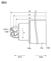
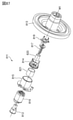
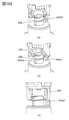
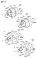
- FIG. 1 is a perspective view of the drum coupling 143.
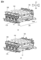
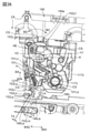
- FIG. 2 is a schematic cross-sectional view of the image forming apparatus.
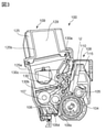
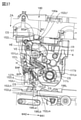
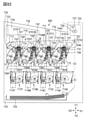
- FIG. 3 is a cross-sectional view of the process cartridge.
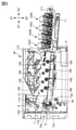
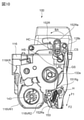
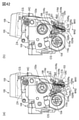
- FIG. 4 is a cross-sectional view of the image forming apparatus.
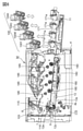
- FIG. 5 is a cross-sectional view of the image forming apparatus.
- FIG. 6 is a cross-sectional view of the image forming apparatus.
- FIG. 7 is a partial detailed view of the tray.
- FIG. 8 is a perspective view of the storage element pressing unit and the cartridge pressing unit.
- FIG. 9 is a partial perspective view of the image forming apparatus.
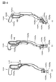
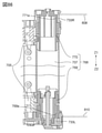
- FIG. 10 is a side view (partial cross-sectional view) of the process cartridge.
- FIG. 11 is a cross-sectional view of the image forming apparatus.
- FIG. 12 is a perspective view of the development separation control unit.
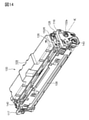
- FIG. 13 is an assembly perspective view of the process cartridge.
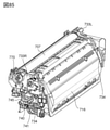
- FIG. 14 is a perspective view of the process cartridge.
- FIG. 15 is an assembly perspective view of the process cartridge.
- FIG. 16 is an assembly perspective view of the process cartridge.
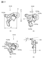
- FIG. 17 is a single item diagram of the separation holding member R.
- FIG. 18 is a single item diagram of the force applying member R.
- FIG. 19 is a partial cross-sectional view after assembling the separation holding member R.
- FIG. 20 is an enlarged view around the separation holding member R.
- FIG. 21 is an enlarged view around the separation holding member R.
- FIG. 22 is a bottom view of the drive side of the process cartridge.
- FIG. 23 is a diagram showing the operation of the developing unit in the main body of the image forming apparatus.
- FIG. 24 is a diagram showing the operation of the developing unit in the main body of the image forming apparatus.
- FIG. 25 is a diagram showing the operation of the developing unit in the main body of the image forming apparatus.
- FIG. 26 is a diagram showing the operation of the developing unit in the main body of the image forming apparatus.
- FIG. 27 is a diagram showing the operation of the developing unit in the main body of the image forming apparatus.
- FIG. 28 is a single item diagram of the separation holding member L.
- FIG. 29 is a single item diagram of the force applying member L.
- FIG. 30 is an assembly perspective view after assembling the developing pressure spring and the separation holding member L.
- FIG. 31 is a partial cross-sectional view after assembling the separation holding member L.
- FIG. 32 is an enlarged view of the periphery of the separation holding member L and the force applying member L.
- FIG. 33 is an enlarged view of the periphery of the separation holding member.
- FIG. 34 is a side view seen from the drive side with the process cartridge mounted inside the image forming apparatus main body.
- FIG. 35 is a diagram showing a process cartridge in the main body of the image forming apparatus.
- FIG. 36 is a diagram showing the operation of the developing unit in the main body of the image forming apparatus.
- FIG. 37 is a diagram showing the operation of the developing unit in the main body of the image forming apparatus.
- FIG. 38 is a diagram showing the operation of the developing unit in the main body of the image forming apparatus.
- FIG. 39 is a diagram showing the operation of the developing unit in the main body of the image forming apparatus.
- FIG. 40 is a diagram showing the arrangement of the separation holding member R and the force applying member.
- FIG. 41 is a diagram showing the arrangement of the separation holding member and the force applying member.
- FIG. 42 is a side view seen from the drive side with the process cartridge 100 mounted inside the image forming apparatus main body.
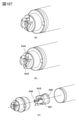
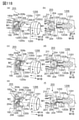
- FIG. 43 is an exploded perspective view of the drive transmission unit 203.
- FIG. 44 is a cross-sectional view of the drive transmission unit 203.
- FIG. 45 is a perspective view of the drive transmission unit 203.
- FIG. 46 is a cross-sectional perspective view of the main body of the device including the drive transmission unit 203.
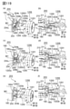
- FIG. 47 is a front view of the drive transmission unit 203 and the drum coupling 143.
- FIG. 48 is a developed view illustrating the engagement of the drum coupling.
- FIG. 49 is a developed view illustrating the engagement of the drum coupling.
- FIG. 50 is a developed view illustrating the engagement of the drum coupling.
- FIG. 51 is a cross-sectional view illustrating the engagement of the drum coupling.
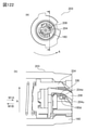
- FIG. 52 is a perspective view illustrating a modified example of the drum coupling.
- FIG. 53 is a developed view illustrating the engagement of the drum coupling.
- FIG. 54 is a developed view illustrating the engagement of the drum coupling.
- FIG. 55 is a perspective view of the drum unit for showing the drum coupling.
- FIG. 56 is a diagram of a drum unit for showing a drum coupling.
- FIG. 57 is a perspective view of the drum unit for showing the drum coupling.
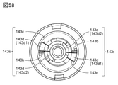
- FIG. 58 is a top view of the drum coupling.
- FIG. 59 is a perspective view showing the parts of the drive transmission unit.
- FIG. 60 is a perspective view of the drive transmission unit and the drum unit.
- FIG. 61 is a perspective view of the drive transmission unit and the drum unit.
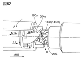
- FIG. 62 is a perspective view of the drive transmission unit and the drum unit.
- FIG. 63 is a perspective view of the drive transmission unit and the drum unit.
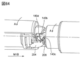
- FIG. 64 is a perspective view of the drive transmission unit and the drum unit.
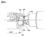
- FIG. 65 is a perspective view of the drive transmission unit and the drum unit.
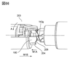
- FIG. 66 is a perspective view of the drive transmission unit and the drum unit.
- FIG. 67 is a perspective view of the drive transmission unit and the drum unit.
- FIG. 68 is a perspective view of the drive transmission unit and the drum unit.
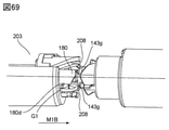
- FIG. 69 is a perspective view of the drive transmission unit and the drum unit.
- FIG. 70 is a perspective view of the drive transmission unit and the drum unit.
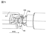
- FIG. 71 is a perspective view of the drive transmission unit and the drum unit.
- FIG. 72 is a perspective view of the drive transmission unit and the drum unit.
- FIG. 73 is a perspective view showing a modified example of the drum coupling.
- FIG. 74 is a perspective view and a front view showing a modified example of the drum coupling.
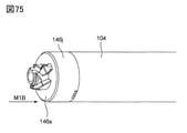
- FIG. 75 is a perspective view of the drum unit.
- FIG. 76 is a developed view illustrating the engagement of the drum coupling.
- FIG. 77 is a perspective view of the drum unit and a front view of the coupling.
- FIG. 78 is a perspective view of the drum unit and the drive transmission unit.
- FIG. 79 is a side view, a perspective view, and a front view of the coupling.
- FIG. 80 is a side view of the coupling.
- FIG. 81 is a side view and a perspective view of the coupling.
- FIG. 82 is a schematic cross-sectional view of the image forming apparatus.
- FIG. 83 is a schematic cross-sectional view of the process cartridge.
- FIG. 84 is a schematic perspective view of the process cartridge.
- FIG. 85 is a schematic perspective view of the process cartridge.
- FIG. 86 is a schematic cross-sectional view of the process cartridge cut at the center of the rotation axis of the photoconductor drum.
- FIG. 87 is an exploded perspective view of the drive transmission unit 811.
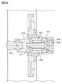
- FIG. 88 is a cross-sectional view of the drive transmission unit 811 attached to the main body of the image forming apparatus, cut at the center of the rotation axis.
- FIG. 89 is a schematic perspective view of another form of the drum coupling 770.
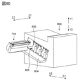
- FIG. 90 is a schematic perspective view for explaining the mounting of the cartridge 701 on the image forming apparatus main body 800.
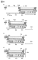
- FIG. 91 is a schematic cross-sectional view for explaining the mounting operation of the cartridge 701 on the image forming apparatus main body 800.
- FIG. 92 is a schematic cross-sectional view for explaining the mounting operation of the drum coupling 770 to the main body drive transmission unit 811.
- FIG. 93 is a schematic cross-sectional view for explaining the mounting operation of the drum coupling 770 to the main body drive transmission unit 811.
- FIG. 94 is a perspective view illustrating another form of the process cartridge.
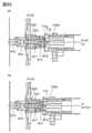
- FIG. 95 is a cross-sectional view of the drum unit.
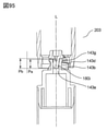
- FIG. 96 is a front view of the coupling.
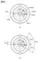
- FIG. 97 (a) is a perspective view of the coupling
- FIG. 97 (b) is a front view.
- FIG. 98 is a front view of the coupling.
- FIG. 99 is a perspective view showing an engaged state between the coupling and the brake engaging member.
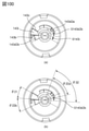
- FIG. 100 is a front view of the coupling.
- FIG. 101 is a front view of the coupling.
- FIG. 102 is a front view, a perspective view, and a side view of the coupling.
- FIG. 103 is a perspective view showing an engaged state between the coupling and the brake engaging member.
- FIG. 104 is a perspective view and a side view of the drum unit.
- FIG. 105 is a perspective view of the drum unit and a front view of the coupling.
- FIG. 106 is a cross-sectional view of the drum unit.
- FIG. 107 is a perspective view of the drum unit.
- FIG. 108 is a cross-sectional view of the coupling.
- FIG. 109 is a perspective view of the drum unit.
- FIG. 110 is a cross-sectional view of the drum unit and the drive transmission unit.
- FIG. 111 is a perspective view of the drum coupling 1100.
- FIG. 112 is an enlarged perspective view of the drum coupling 1100.
- FIG. 113 is a front view of the drum coupling 1100.
- FIG. 114 is a perspective view showing a modified example of the drum coupling 1100.
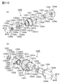
- FIG. 115 is an exploded perspective view of the drum coupling 1206.
- FIG. 116 is a cross-sectional view of the drum coupling 1206.
- FIG. 117 is a perspective view showing the operation of the drum coupling 1206.
- FIG. 118 is a perspective view and a cross-sectional view showing the operation of the drum coupling 1206.
- FIG. 119 is a perspective view and a cross-sectional view showing the operation of the drum coupling 1206.
- FIG. 120 is a perspective view and a cross-sectional view showing the operation of the drum coupling 1206.
- FIG. 121 is a perspective view and an exploded perspective view of the drive transmission unit 203.
- FIG. 122 is a side view and a cross-sectional view of the drive transmission unit 203.
- FIG. 123 is an exploded perspective view of the drum coupling 1342.
- FIG. 124 is a front view and a perspective view of the drum coupling 1342.
- FIG. 125 is a perspective view showing the engagement operation between the drum coupling 1342 and the drive transmission unit 203.
- FIG. 126 is a cross-sectional view showing the engagement operation between the drum coupling 1342 and the drive transmission unit 203.
- FIG. 127 is a cross-sectional view showing the engagement operation between the drum coupling 1342 and the drive transmission unit 203.
- FIG. 128 is a perspective view showing the engagement operation between the drum coupling 1342 and the drive transmission unit 203.
- FIG. 129 is a cross-sectional view showing the engagement operation between the drum coupling 1342 and the drive transmission unit 203.
- FIG. 130 is a cross-sectional view showing the engagement operation between the drum coupling 1342 and the drive transmission unit 203.
- FIG. 131 is a front view of the drum coupling 1342.
- FIG. 132 is a perspective view showing the internal structure of the drum coupling 1206.
- FIG. 133 is a perspective view and a front view of the second brake engaging member 208.
- FIG. 134 is an exploded perspective view of the drum coupling 1545.
- FIG. 135 is a front view and a cross-sectional view of the engaging member 1543 as viewed from the drive side.
- FIG. 136 is a perspective view, a front view, and a cross-sectional view showing the engagement between the engaging member 1543 and the flange member 1544.
- FIG. 137 is a front perspective view and an engagement diagram of the drum coupling 1545 and the drive transmission unit 203.
- FIG. 138 is a cross-sectional view of the drum coupling 1545 and the drive transmission unit 203 before and after engagement.
- FIG. 139 is a perspective view showing the drive transmission of the second brake engaging member 208 and the drum drive coupling 180.
- FIG. 140 is a side view and a cross-sectional view of the second brake engaging member 208 and the drive transmission unit 203.
- FIG. 141 is a diagram showing a deformed state of the second brake engaging member 208.
- FIG. 142 is a cross-sectional perspective view of the drum coupling 1545 and the drive transmission unit 203.
- FIG. 143 is a cross-sectional view of the drum coupling 1545 and the drive transmission unit 203.
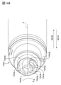
- FIG. 144 is a perspective view of another form of drum coupling 1546.
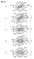
- FIG. 145 is a front view of the drum coupling.
- FIG. 146 is a front view of the drum coupling.
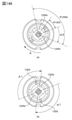
- FIGS. 147 (a) and 147 (b) are perspective views of the drum coupling.
- FIG. 147 (c) is a diagram showing a diameter work state of the drive transmission unit and the engaging member.
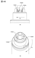
- FIG. 148 is a perspective view of the drum coupling.
- FIG. 149 (a) is a side view of the drum coupling.
- FIG. 149 (b) is a perspective view of the drum coupling.
- FIG. 150 (a) is a front view of the drum coupling.
- FIG. 150 (b) is a perspective view of the drum coupling.
- an image forming apparatus to which four process cartridges can be attached and detached is exemplified as an image forming apparatus.
- the number of process cartridges to be attached to the image forming apparatus is not limited to this. It is set as needed.
- a laser beam printer is exemplified as one aspect of the image forming apparatus.
- a laser beam printer is exemplified as one aspect of the image forming apparatus.
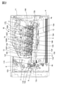
- FIG. 2 is a schematic cross-sectional view of the image forming apparatus M. Further, FIG. 3 is a cross-sectional view of the process cartridge 100.
- This image forming apparatus M is a four-color full-color laser printer using an electrophotographic process, and forms a color image on a recording medium S.
- the image forming apparatus M is a process cartridge type, and the process cartridge is detachably attached to the image forming apparatus main body (device main body, electrophotographic image forming apparatus main body) 170 to form a color image on the recording medium S. ..
- the side provided with the front door 11 is referred to as the front surface (front surface), and the surface opposite to the front surface is referred to as the back surface (rear surface).
- the right side of the image forming apparatus M when viewed from the front is referred to as a driving side
- the left side is referred to as a non-driving side.
- FIG. 2 is a cross-sectional view of the image forming apparatus M as viewed from the non-driving side.
- the front of the paper is the non-driving side of the image forming apparatus M
- the right side of the paper is the front of the image forming apparatus M
- the back of the paper is the driving of the image forming apparatus M. Be on the side.
- the drive side of the process cartridge 100 is the side on which the drum coupling (photoreceptor coupling) described later is arranged in the axial direction of the photoconductor drum. Further, the drive side of the process cartridge 100 is also the side on which the development coupling described later is arranged in the axial direction of the development roller (development member).
- the axial direction of the photoconductor drum is a direction parallel to the rotation axis of the photoconductor drum described later.
- the axial direction of the developing roller is a direction parallel to the rotation axis of the developing roller described later.
- the axis of the photoconductor drum and the axis of the developing roller are substantially parallel, so that the axis direction of the photoconductor drum and the axis direction of the developing roller are substantially the same.
- the image forming apparatus main body 170 has four process cartridges 100 (100Y, 100M, 100C, 100K) of a first process cartridge 100Y, a second process cartridge 100M, a third process cartridge 100C, and a fourth process cartridge 100K. It is arranged almost horizontally.
- Each of the first to fourth process cartridges 100 (100Y, 100M, 100C, 100K) has the same electrophotographic process mechanism, and the color of the developer (hereinafter referred to as toner) is different. .. Rotational driving force is transmitted from the drive output unit (details will be described later) of the image forming apparatus main body 170 to the first to fourth process cartridges 100 (100Y, 100M, 100C, 100K).
- a bias voltage (charging bias, development bias, etc.) is supplied from the image forming apparatus main body 170 to each of the first to fourth process cartridges 100 (100Y, 100M, 100C, 100K) (not shown).
- each of the first to fourth process cartridges 100 (100Y, 100M, 100C, 100K) of this embodiment is used as a photoconductor drum 104 and a process means acting on the photoconductor drum 104. It has a drum holding unit 108 provided with charging means. Further, each of the first to fourth process cartridges 100 (100Y, 100M, 100C, 100K) has a developing unit 109 provided with a developing means for developing an electrostatic latent image on the photoconductor drum 104.
- the drum holding unit 108 and the developing unit 109 are coupled to each other. A more specific configuration of the process cartridge 100 will be described later.
- the first process cartridge 100Y accommodates yellow (Y) toner in the developing frame 125, and forms a yellow toner image on the surface of the photoconductor drum 104.
- the second process cartridge 100M contains magenta (M) toner in the developing frame body 125, and forms a magenta-colored toner image on the surface of the photoconductor drum 104.
- the third process cartridge 100C contains a cyan (C) toner in the developing frame 125, and forms a cyan toner image on the surface of the photoconductor drum 104.
- the fourth process cartridge 100K contains black (K) toner in the developing frame 125, and forms a black toner image on the surface of the photoconductor drum 104.
- a laser scanner unit 14 as an exposure means is provided above the first to fourth process cartridges 100 (100Y, 100M, 100C, 100K). The laser scanner unit 14 outputs the laser beam U corresponding to the image information. Then, the laser beam U passes through the exposure window 110 of the process cartridge 100 and scans and exposes the surface of the photoconductor drum 104.
- An intermediate transfer unit 12 as a transfer member is provided below the first to fourth process cartridges 100 (100Y, 100M, 100C, 100K).
- the intermediate transfer unit 12 has a drive roller 12e, a turn roller 12c, and a tension roller 12b, and a flexible transfer belt 12a is hung on the intermediate transfer unit 12.
- the lower surface of the photoconductor drum 104 of each of the first to fourth process cartridges 100 (100Y, 100M, 100C, 100K) is in contact with the upper surface of the transfer belt 12a.
- the contact part is the primary transfer part.
- a primary transfer roller 12d is provided inside the transfer belt 12a so as to face the photoconductor drum 104.
- the secondary transfer roller 6 is brought into contact with the turn roller 12c via the transfer belt 12a.
- the contact portion between the transfer belt 12a and the secondary transfer roller 6 is the secondary transfer portion.
- a feeding unit 4 is provided below the intermediate transfer unit 12.
- the feeding unit 4 has a paper feed tray 4a and a paper feed roller 4b in which the recording medium S is loaded and accommodated.
- a fixing device 7 and a paper ejection device 8 are provided on the upper left side of the image forming apparatus main body 170 in FIG. 2.
- the upper surface of the image forming apparatus main body 170 is a paper ejection tray 13.
- the toner image of the recording medium S is fixed by the fixing means provided in the fixing device 7, and the toner image is discharged to the paper ejection tray 13.
- the operation for forming a full-color image is as follows.
- the photoconductor drum 104 of each of the first to fourth process cartridges 100 (100Y, 100M, 100C, 100K) is rotationally driven at a predetermined speed (FIG. 3, arrow A direction).
- the transfer belt 12a is also rotationally driven in the forward direction (direction of arrow C in FIG. 2) with respect to the rotation of the photoconductor drum at a speed corresponding to the speed of the photoconductor drum 104.
- the laser scanner unit 14 is also driven. In synchronization with the drive of the laser scanner unit 14, the charging roller 105 uniformly charges the surface of the photoconductor drum 104 to a predetermined polarity and potential in each process cartridge. The laser scanner unit 14 scans and exposes the surface of each photoconductor drum 104 with laser light U according to the image signals of each color.
- an electrostatic latent image corresponding to the image signal of the corresponding color is formed on the surface of each photoconductor drum 104.
- the formed electrostatic latent image is developed by a developing roller 106 that is rotationally driven at a predetermined speed. That is, the developing roller 106 is in contact with the photoconductor drum 104, and the toner moves from the developing roller 106 to the latent image of the photoconductor drum 104, so that the latent image is developed as a toner image.
- the contact developing method is adopted, and the developing roller 106 and the photoconductor drum 104 are brought into contact with each other.
- a non-contact developing method is adopted in which a minute gap is left between the developing roller 106 and the photoconductor drum 104 to fly toner from the developing roller 106 to the photoconductor drum 104.
- a yellow toner image corresponding to the yellow component of the full-color image is formed on the photoconductor drum 104 of the first process cartridge 100Y. Then, the toner image is primaryly transferred onto the transfer belt 12a. A part of the photoconductor drum 104 is exposed to the outside of the cartridge and is in contact with the transfer belt 12a. At this contact portion, the toner image on the surface of the photoconductor drum 104 moves to the transfer belt 12a.
- a magenta color toner image corresponding to the magenta component of the full color image is formed on the photoconductor drum 104 of the second process cartridge 100M. Then, the toner image is superimposed on the yellow toner image already transferred on the transfer belt 12a and primary transfer is performed.
- a cyan toner image corresponding to the cyan component of the full-color image is formed on the photoconductor drum 104 of the third process cartridge 100C. Then, the toner image is superimposed on the yellow-colored and magenta-colored toner images that have already been transferred onto the transfer belt 12a, and the toner image is first transferred.
- a black toner image corresponding to the black component of the full-color image is formed on the photoconductor drum 104 of the fourth process cartridge 100K. Then, the toner image is superimposed on the yellow-colored, magenta-colored, and cyan-colored toner images already transferred onto the transfer belt 12a, and the toner image is first transferred.
- the recording media S are separated and fed one by one at a predetermined control timing.
- the recording medium S is introduced into the secondary transfer portion, which is the contact portion between the secondary transfer roller 6 and the transfer belt 12a, at a predetermined control timing.
- the toner images of the four colors superimposed on the transfer belt 12a are sequentially collectively transferred to the surface of the recording medium S.
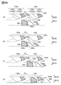
- FIG. 4 is a cross-sectional view of the image forming apparatus M in which the tray 171 is located inside the image forming apparatus main body 170 with the front door 11 open.
- FIG. 5 is a cross-sectional view of the image forming apparatus M in a state where the tray 171 is located outside the image forming apparatus main body 170 with the front door 11 open and the process cartridge 100 is housed inside the tray.
- FIG. 6 is a cross-sectional view of the image forming apparatus M in a state where the tray 171 is located outside the image forming apparatus main body 170 with the front door 11 open and the process cartridge 100 is removed from the tray.
- FIG. 7A is a partial detailed view of the tray 171 as viewed from the drive side in the state of FIG.
- FIG. 7B is a partial detailed view of the tray 171 as viewed from the non-driving side in the state of FIG.
- the tray 171 can be moved in the arrow X1 direction (pushing direction) and the arrow X2 direction (pulling direction) with respect to the image forming apparatus main body 170. That is, the tray 171 is provided so as to be retractable and pushable with respect to the image forming apparatus main body 170, and the tray 171 is configured to be movable in a substantially horizontal direction when the image forming apparatus main body 170 is installed on a horizontal plane. ..
- the state in which the tray 171 is located outside the image forming apparatus main body 170 (the state shown in FIG. 5) is referred to as an outside position.
- an inner position a state in which the tray 171 is located inside the image forming apparatus main body 170 with the front door 11 open and the photoconductor drum 104 and the transfer belt 12a are separated from each other (state in FIG. 4) is referred to as an inner position.
- the tray 171 has a mounting portion 171a in which the process cartridge 100 can be detachably mounted as shown in FIG. 6 at the outer position. Then, each process cartridge 100 mounted on the mounting portion 171a at the outer position of the tray 171 is supported by the tray 171 by the drive side cartridge cover member 116 and the immovable side cartridge cover member 117 as shown in FIG. 7. Then, the process cartridge 100 moves to the inside of the image forming apparatus main body 170 with the movement of the tray 171 in a state of being arranged in the mounting portion 171a. At this time, the transfer belt 12a moves with a gap between the photoconductor drum 104. The tray 171 can move the process cartridge 100 inside the image forming apparatus main body 170 without the photoconductor drum 104 coming into contact with the transfer belt 12a (details will be described later).
- the tray 171 allows a plurality of process cartridges 100 to be collectively moved to a position where image formation is possible inside the image forming apparatus main body 170, and is collectively moved to the outside of the image forming apparatus main body 170. Can be pulled out. [Positioning of process cartridge to the main body of the electrophotographic image forming device]
- the tray 171 is provided with positioning portions 171VR and 171VL for holding the cartridge 100, respectively.
- the positioning portion 171VR has straight portions 171VR1 and 171VR2, respectively.
- the arcuate portions 116VR1 and 116VR2 of the cartridge cover member 116 shown in FIG. 7 come into contact with the straight portions 171VR1 and 171VR2 to determine the center of the photoconductor drum.
- the tray 171 shown in FIG. 7 has a rotation-determining convex portion 171KR.
- the posture of the process cartridge 100 is determined with respect to the apparatus main body 170 by fitting with the rotation determination recess 116KR position of the cartridge cover member 116 shown in FIG. 7.
- the positioning portion 171VL and the rotation determining convex portion 171KL are arranged at positions (non-driving side) facing each other across the intermediate transfer belt 12a in the longitudinal direction of the positioning portion 171VR and the process cartridge 100. That is, on the non-driving side as well, the position of the process cartridge 100 is determined by the arc portions 117VL1 and 117VL2 of the cartridge cover member 117 engaging with the positioning portion 171VL and the rotation determining recess 117KL engaging with the rotation determining convex portion 171KL.
- the process cartridge 100 integrated with the tray 171 is moved in the direction of the arrow X1 and inserted to the position shown in FIG.
- the process cartridge 100 is pressed by a cartridge pressing mechanism (not shown) described later, and is fixed to the image forming apparatus main body 170 together with the tray 171. Further, the transfer belt 12a comes into contact with the photoconductor 104 in conjunction with the operation of the cartridge pressing mechanism. In this state, an image is formed (FIG. 2).
- the positioning unit 171VR and the positioning unit 171V also serve as a reinforcing role for maintaining the rigidity in the drawing operation of the tray 171, and therefore, a metal sheet metal is used, but the present invention is not limited to this. .. [Cartridge pressing mechanism]
- FIG. 8A shows only the process cartridge 100, the tray 171 and the cartridge pressing mechanisms 190 and 191 and the intermediate transfer unit 12 in the state of FIG.
- FIG. 8B shows only the process cartridge 100, the tray 171 and the cartridge pressing mechanisms 190 and 191 and the intermediate transfer unit 12 in the state of FIG.
- the process cartridge 100 receives a driving force during image formation, and further receives a reaction force from the primary transfer roller 12d (FIG. 2) in the direction of arrow Z1. Therefore, it is necessary to press the process cartridge in the Z2 direction in order to maintain a stable posture without the process cartridge floating from the positioning portions 171VR and 171VL during the image forming operation.
- the image forming apparatus main body 170 is provided with a cartridge pressing mechanism (190, 191).
- the storage element pressing unit 190 is responsible for the non-driving side
- the cartridge pressing unit 191 is responsible for the driving side. This will be described in more detail below.
- the storage element pressing unit 190 mainly has a main body side electric contact (not shown) that comes into contact with the electric contact of the storage element (not shown) provided in the process cartridge 100.
- a link mechanism (not shown)
- the storage element 140 and the electric contact on the main body side can be brought into contact with each other and can not be contacted with each other.
- the contacts are in contact with each other by closing the front door 11, and the contacts are separated by opening the front door 11.
- the storage element pressing unit 190 also plays a role of pressing the process cartridge 100 against the above-mentioned positioning unit 171VR.
- the cartridge pressing unit 121 similarly to the storage element pressing unit 190, the cartridge pressing unit 121 also descends in the direction of arrow Z2 in conjunction with the operation of closing the front door 11 and plays a role of pressing the process cartridge 100 against the above-mentioned positioning unit 171VL.
- the cartridge pressing pressing mechanism (190, 191) also plays a role of pushing down the force applying members 152L and 152R of the process cartridge 100 described later.
- Drive transmission mechanism [Drive transmission mechanism]
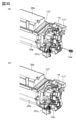
- FIG. 9A is a perspective view in which the process cartridge 100 and the tray 171 are omitted in the state of FIG. 4 or FIG.
- FIG. 9B is a perspective view in which the process cartridge 100, the front door 11 and the tray 171 are omitted.
- FIG. 10 is a side view of the process cartridge 100 as viewed from the drive side.
- the process cartridge in the present embodiment has a developing coupling portion 32a and a drum coupling (photoreceptor coupling) 143.
- the main body side drum drive coupling 180 and the main body side development drive coupling 185 that drive and transmit to the process cartridge 100 are in the arrow Y1 direction by a link mechanism (not shown). It has a structure that protrudes from the door.
- the drum drive coupling 180 and the development drive coupling 185 are configured to retract in the direction of arrow Y2.
- the structure By retracting each coupling from the insertion / removal trajectory (X1 direction, X2 direction) of the process cartridge, the structure does not hinder the insertion / removal of the tray 171.
- the drum drive coupling 180 described above engages with the drum coupling (coupling member, cartridge side coupling) 143.
- the development drive coupling 185 on the main body side engages with the development coupling portion 32a.
- the drive transmission to the process cartridge 100 is not limited to two places as described above, and a mechanism for inputting the drive only to the drum coupling and transmitting the drive to the developing roller may be provided.
- the intermediate transfer unit 12 rises in the direction of arrow R2 by a link mechanism (not shown) by closing the front door 11, and the position at the time of image formation (photoreceptor drum 104 and intermediate transfer belt 12a come into contact with each other). It is configured to move to the position).
- the intermediate transfer unit 12 descends in the direction of the arrow R1, and the photoconductor drum 2 and the intermediate transfer belt 12a are separated from each other.
- the photoconductor drum 104 and the intermediate transfer belt 12a come into contact with each other and separate from each other according to the opening / closing operation of the front door 11.
- the contact separation operation has a configuration in which the intermediate transfer unit 12 rises and falls while drawing a rotation locus centered on the center point PV1 shown in FIG.
- This receives a force from a gear (not shown) arranged coaxially with the PVI, and the intermediate transfer belt 12a is driven. Therefore, by setting the above-mentioned position PV1 as the rotation center, the intermediate transfer unit 12 can be raised and lowered without moving the gear center. By doing so, it is not necessary to move the center of the gear, and it is possible to maintain the position of the gear with high accuracy.
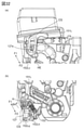
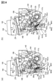
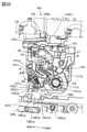
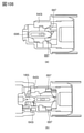
- FIG. 11 is a cross-sectional view of the image forming apparatus M cut at the drive side end face of the process cartridge 100.
- FIG. 12 is a perspective view of the development separation control unit as viewed diagonally from above.
- the development separation control unit 195 controls the separation contact operation of the development unit 109 with respect to the photoconductor drum 104 by engaging with a part of the development unit 109.
- the development separation control unit 195 is located below the image forming apparatus main body 170 as shown in FIG.
- the development separation control unit 195 is arranged vertically below the development input coupling portion 32a and the drum coupling 143 (downward in the arrow Z2 direction).
- the development separation control unit 195 is arranged in the longitudinal direction (Y1, Y2 direction) of the photoconductor drum 104 of the intermediate transfer belt 12. That is, the development separation control unit 195 has a development separation control unit 195R on the drive side and a development separation control unit 195L on the non-drive side.
- the main body can be miniaturized.
- the development separation control unit 195R has four separation control members 196R corresponding to the process cartridge 100 (100Y, 100M, 100C, 100K).
- the four separation control members have substantially the same shape.
- the development separation control unit 195R is always fixed to the image forming apparatus main body.
- the separation control member 196R is configured to be movable in the W41 and W42 directions by a control mechanism (not shown). The detailed configuration will be described later.
- the development separation control unit 195L has four separation control members 196L corresponding to the process cartridge 100 (100Y, 100M, 100C, 100K).
- the four separation control members have substantially the same shape.
- the development separation control unit 195L is always fixed to the image forming apparatus main body.
- the separation control member 196L is configured to be movable in the W41 and W42 directions by a control mechanism (not shown). The detailed configuration will be described later.
- a part of the development control unit 196 and a part of the development unit 109 It is necessary to overlap in the vertical direction (Z1, Z2 direction).
- a method is adopted in which the development separation control unit 195 is fixed to the image forming apparatus main body 170, and a part of the developing unit 109 (force applying member 152) is projected downward (Z2) in the image forming apparatus main body 170.
- the mechanism for projecting the force applying member 152 directly uses the mechanisms of the storage element pressing unit 190 and the cartridge pressing unit 191 described above, there is no problem as described above and an increase in the cost of the main body of the device can be suppressed.
- the entire unit of the development separation control unit 195 is fixed to the image forming apparatus main body 170. However, as will be described later, a part of the developing unit 109 is movable in order to engage with the force applying member 152 to give an operation so that the developing unit 109 is in a separated state and an abutting state with respect to the photoconductor drum 104. It is a possible configuration. Details will be described later. [Overall configuration of process cartridge]
- FIG. 13 is an assembly perspective view of the process cartridge 100 as viewed from the drive side, which is one side in the axial direction of the photoconductor drum 104.
- FIG. 14 is a perspective view of the process cartridge 100 as viewed from the drive side.
- the first to fourth process cartridges 100 (100Y, 100M, 100C, 100K) have the same electrophotographic process mechanism, and the color of the contained toner and the filling amount of the toner are different from each other. It is a thing.
- the process cartridge 100 includes a photoconductor drum 104 (4Y, 4M, 4C, 4K) and a process means for acting on the photoconductor drum 104.
- the cartridge 100 has a charging roller 105 which is a charging means (charging member) for charging the photoconductor drum 104.
- the cartridge 100 includes a developing roller 106 which is a developing means (developing member) for developing a latent image formed on the photoconductor drum 104 as another process means.
- a cleaning means for example, a cleaning blade or the like
- the image forming apparatus of this embodiment adopts a configuration in which a cleaning means for contacting the photoconductor drum 104 is not provided.
- the process cartridge 100 is divided into a drum holding unit 108 (108Y, 108M, 108C, 108K) and a developing unit 109 (109Y, 109M, 109C, 109K).
- a drum holding unit 108 108Y, 108M, 108C, 108K
- a developing unit 109 109Y, 109M, 109C, 109K
- the drum holding unit 108 is composed of a photoconductor drum 104, a charging roller 105, a drum frame 115 which is a first frame, and the like.
- the photoconductor drum 104 is integrated with the coupling 143 and the drum flange 142 as a drum unit 103 (see FIG. 1A; details will be described later).
- the drum unit 103 is rotatably supported by a drive-side cartridge cover member 116 and a non-moving-side cartridge cover member 117 provided at both ends in the longitudinal direction of the process cartridge 100.
- the drive-side cartridge cover member 116 and the non-moving-side cartridge cover member 117 will be described later.
- a drum coupling 143 for transmitting a driving force to the photoconductor drum 104 is provided in the vicinity of one end in the longitudinal direction of the photoconductor drum 104.
- the coupling 143 engages with the main body side drum drive coupling 180 (see FIG. 9) as the drum drive output unit of the image forming apparatus main body 170.
- the driving force of the driving motor (not shown) of the image forming apparatus main body 170 is transmitted to the photoconductor drum 104 and rotated in the direction of arrow A.
- the photoconductor drum 104 has a drum flange 142 in the vicinity of the other end (second end portion) in the longitudinal direction.
- the shaft portion 143j (see FIG. 1) of the coupling 143 is supported by the drive side cartridge cover 116, and the drum flange 142 is supported by the shaft fixed to the non-drive side cartridge cover 117.
- the drum unit 103 is rotatably supported in the cartridge. That is, both ends of the photoconductor drum 104 are rotatably supported by both ends of the casing of the cartridge (that is, the cartridge covers 116 and 117) via the coupling 143 and the drum flange 142.
- the charging roller 105 is supported by the drum frame 115 so that it can come into contact with the photoconductor drum 104 and rotate in a driven manner.
- the side on which the coupling 143 is arranged is the drive side
- the side on which the drum flange 142 is arranged is the non-drive side. That is, of both ends of the photoconductor drum 104 in the axial direction, the coupling 143 is fixed near the end on the drive side, and the drum flange 142 is fixed near the end on the opposite side to the drive side.
- the photoconductor drum 104 one may be referred to as a first end and the other may be referred to as a second end.
- FIG. 80 shows the end portion 104a on the drum drive side and the end portion 104b on the non-drive side of the photoconductor drum.
- FIGS. 10 and 19 are views showing the drive side of the cartridge.
- FIG. 16 is a diagram showing a non-driving side of the cartridge.
- the drive-side cartridge cover 116 is a component located at the drive-side end of the casing of the cartridge 100, and the non-drive-side cartridge cover 117 is the non-drive-side end of the casing. It is a part located in.
- the drum coupling 143 supported by the drive-side cartridge cover 116 can be considered to be located near the non-drive-side end of the casing of the cartridge 100.
- both ends of the cartridge 100 one may be referred to as a first end and the other may be referred to as a second end.
- the developing unit 109 is composed of a developing roller 106, a toner transfer roller (toner supply roller) 107, a developing blade 130, a developing frame 125, and the like.
- the developing frame body 125 is composed of a lower frame body 125a and a lid member 125b.
- the lower frame body 125a and the lid member 125b are connected by ultrasonic welding or the like.
- the developing frame body 125 which is the second frame body (second casing), has a toner storage unit 129 for storing the toner supplied to the developing roller 106. Further, the developing frame body 125 rotatably supports the developing roller 106 and the toner transfer roller 107 via the driving side bearing 126 and the non-driving side bearing 127, which will be described later, and regulates the toner layer thickness on the peripheral surface of the developing roller 106. Holds the developing blade 130 to be processed.
- the developing blade 130 is formed by attaching an elastic member 130b, which is a sheet-like metal having a thickness of about 0.1 mm, to a support member 130a, which is a metal material having an L-shaped cross section, by welding or the like.
- the developing blade 130 is attached to the developing frame body 125 with fixing screws 130c at two locations, one near one end and the other near the other end in the longitudinal direction.
- the developing roller 106 is composed of a core metal 106c made of a metal material and a rubber portion 106d.
- the developing roller 106 is rotatably supported by a driving side bearing 126 and a non-driving side bearing 127 attached to both ends in the longitudinal direction of the developing frame body 125.
- the developing frame body 125, the drive side bearing 126, and the non-drive side bearing 127 are a part of the frame body (casing) of the cartridge.
- the bearings 126 and 127 may be regarded as a part of the developing frame body 125, and the bearings 126 and 127 and the developing frame body 125 may be collectively referred to as a developing frame body.
- the developing roller 106 is a roller for supporting the toner for developing the latent image of the photoconductor drum 104.
- the toner transfer roller 107 conveys and supplies the toner contained in the toner accommodating portion 129 toward the developing roller 106.
- the toner transfer roller 107 is in contact with the developing roller 106.
- a development input coupling unit (development coupling) 32a for transmitting a driving force to the development unit 109 is provided on one side of the development unit 109 in the longitudinal direction. There is.
- the development input coupling unit 32a engages with the development drive coupling 185 (see FIG. 9) on the main body side as the development drive output unit of the image forming apparatus main body 170, and the drive motor (not shown) of the image forming apparatus main body 170.
- the driving force is input to the developing unit 109.
- the driving force input to the developing unit 109 is transmitted by a driving row (not shown) provided in the developing unit 109, so that the developing roller 106 can be rotated in the direction of arrow D in FIG. ..
- the driving force received by the development input coupling unit 32a also rotates the toner transfer roller 107 to supply toner to the development roller 106.
- a developing input coupling portion 32a and a developing cover member 128 that supports and covers a drive train are provided on one side of the developing unit 109 in the longitudinal direction.
- the outer diameter of the developing roller 106 is set smaller than the outer diameter of the photoconductor drum 104.
- the outer diameter of the photoconductor drum 104 of this embodiment is set in the range of ⁇ 18 to ⁇ 22, and the outer diameter of the developing roller 106 is set in the range of ⁇ 8 to ⁇ 14. Efficient placement is possible by setting this outer diameter.
- the assembly of the drum holding unit 108 and the developing unit 109 will be described with reference to FIG.
- the drum holding unit 108 and the developing unit 109 are coupled by a drive-side cartridge cover member 116 and a non-moving-side cartridge cover member 117 provided at both ends in the longitudinal direction of the process cartridge 100.
- the drive-side cartridge cover member 116 provided on one side (drive side) of the process cartridge 100 in the longitudinal direction is provided with a developing unit support hole 116a for swinging (moving) the developing unit 109. Has been done.
- the non-driving side cartridge cover member 117 provided on the other side (non-driving side) in the longitudinal direction of the process cartridge 100 the developing unit support hole 117a for swingably supporting the developing unit 109 is provided. Is provided.
- the drive side cartridge cover member 116 and the non-moving side cartridge cover member 117 are provided with drum support holes 116b and 117b for rotatably supporting the photoconductor drum 104.
- the outer diameter portion of the cylindrical portion 128b of the development cover member 128 is fitted into the development unit support hole 116a of the drive side cartridge cover member 116.
- the outer diameter portion of the cylindrical portion (not shown) of the non-driving side bearing 127 is fitted into the developing unit support hole 117a of the non-moving side cartridge cover member 117.
- both ends of the photoconductor drum 104 in the longitudinal direction are fitted into the drum support hole 116b of the drive side cartridge cover member 116 and the drum support hole 117b of the immovable side cartridge cover member 117.
- the drive-side cartridge cover member 116 and the non-moving-side cartridge cover member 117 are fixed to the drum frame 115 of the drum holding unit 108 with screws or adhesives (not shown).
- the developing unit 109 is rotatably supported by the drive-side cartridge cover member 116 and the immovable-side cartridge cover member 117.
- the developing unit 109 can be moved (rotated) with respect to the drum holding unit 108, and the developing roller 106 can be moved with respect to the photoconductor drum 104 by this movement.
- the developing roller 106 can be positioned at a position acting on the photoconductor drum 104.
- the drum frame 115 and the cover members 116 and 117 are part of the cartridge frame (casing). More specifically, these are the frames of the drum holding unit 108. Further, since both cover members 116 and 117 are fixed to one end and the other end of the drum frame 115, the cover members 116 and 117 may be regarded as a part of the drum frame 115. Alternatively, the cover members 116, 117 and the drum frame 115 may be collectively referred to as a drum frame.
- one of the frame body (115, 116, 117) of the drum holding unit 108 and the frame body (125, 126, 127) of the developing unit is the first frame body (first casing), and the other is the second. It may be called a frame body (second casing) or the like.
- the frame body (115, 116, 117) of the drum holding unit 108 and the frame body (125, 126, 127) of the developing unit are not particularly distinguished, and both are comprehensively referred to as the frame body of the cartridge (casing of the cartridge). Sometimes called.
- FIG. 14 shows a state in which the drum holding unit 108 and the developing unit 109 are assembled by the above steps and integrally formed as the process cartridge 100.
- the axis connecting the center of the developing unit support hole 116a of the drive side cartridge cover member 116 and the center of the developing unit support hole 117a of the immovable side cartridge cover member 117 is referred to as a swing axis K.
- the cylindrical portion 128b of the development cover member 128 on the drive side is coaxial with the development input coupling 74. That is, the developing unit 109 has a configuration in which the driving force is transmitted from the image forming apparatus main body 170 on the swing axis K. Further, the developing unit 109 is rotatably supported around the swing shaft K.
- the process cartridge has a separation contact mechanism 150R on the drive side and a separation contact mechanism 150L on the non-drive side.
- FIG. 15 shows an assembly perspective view of the drive side of the developing unit 109 including the separation contact mechanism 150R.
- FIG. 16 shows an assembly perspective view of the development unit 109 including the separation contact mechanism 150L on the non-driving side.
- the separation contact mechanism first, the details of the separation contact mechanism 150R on the drive side will be described, and then the separation contact mechanism 150L on the non-drive side will be described.
- the separation contact mechanism 150R has a separation holding member 151R which is a regulating member, a force applying member 152R which is a pressing member, and a tension spring 153.
- the separation contact mechanism 150L has a separation holding member 151L which is a regulating member, a force applying member 152L which is a pressing member, and a tension spring 153. [Detailed description of separation holding member R]
- FIG. 17A is a front view of a single product as seen from the drive side longitudinal direction of the process cartridge 100 of the separation holding member 151R.
- 17 (b) and 17 (c) are single perspective views of the separation holding member 151R.
- FIG. 17D is a view of the separation holding member 151R viewed in the direction of arrow Z2 in FIG. 17A (vertically upward in the image forming state).
- the separation holding member 151R has an annular support receiving portion 151Ra, and has a separation holding portion 151Rb protruding from the support receiving portion 151Ra in the radial direction of the support receiving portion 151Ra.
- the tip of the separation holding portion 151Rb has a separation holding surface 151Rc having an arc shape centered on the separation holding member swing axis H and an inclination of an angle ⁇ 1 with respect to the line HA parallel to the separation holding member swing axis H. ..
- the angle ⁇ 1 is set so as to satisfy the equation (1). 0 ° ⁇ ⁇ 1 ⁇ 45 ° ... (1)
- the separation holding member 151R has a second regulated surface 151Rk adjacent to the separation holding surface 151Rc. Further, the separation holding member 151R has a second pressed portion 151Rd protruding in the Z2 direction from the support receiving portion 151Ra, and the separation holding member 151R has a second pressed portion 151Rd in the direction of the separation holding member swing axis H of the support receiving portion 151Ra. It has a protruding arc-shaped second pressed surface 151Re.
- the separation holding member 151R has a main body portion 151Rf connected to the support receiving portion 151Ra, and the main body portion 151Rf has a spring hooking portion 151Rg protruding in the distance holding member swing axis H direction of the support receiving portion 151Ra. Further, the main body portion 151Rf has a rotation prevention portion 151Rm protruding in the Z2 direction, and a rotation prevention surface 151Rn is provided in a direction facing the second pressed surface 151Re. [Detailed explanation of force applying member R]
- FIG. 18A is a front view of the force applying member 152R as viewed from the longitudinal direction of the process cartridge 100
- FIGS. 18B and 18C are perspective views of the force applying member 152R.
- the force applying member 152R has an oval-shaped oval support receiving portion 152Ra.
- the longitudinal direction of the oval shape of the oval support receiving portion 152Ra is an arrow LH
- the upper part is an arrow LH1
- the lower part is an arrow LH2.
- the direction in which the elongated round support receiving portion 152Ra is formed is defined as HB.
- the force applying member 152R has a protruding portion 152Rh formed on the downstream side in the arrow LH2 direction of the elongated round support receiving portion 152Ra.
- the oval support receiving portion 152Ra and the protruding portion 152Rh are connected by a main body portion 152Rb.
- the force applying member 152R has a pressed portion 152Re projecting in the arrow LH1 direction and substantially perpendicular to the arrow LH1 direction, and has an arc-shaped pressed surface 152Rf on the downstream side in the arrow LH1 direction and on the upstream side. It has a push-in control surface of 152 Rg. Further, the force applying member 152R is adjacent to the first storage regulation surface 152Rv extending from the main body 152Rb on the upstream side in the arrow LH2 direction from the protrusion 152, and is substantially parallel to the first pressing surface 152Rq. It has a second storage regulation surface 152Rw.
- the protruding portion 152Rh has a first force receiving portion 152Rk and a second force receiving portion 152Rn which are arranged opposite to each other in the direction substantially orthogonal to the arrow LH2 direction and the terminal portion in the arrow LH2 direction.
- the first force receiving portion 152Rk and the second force receiving portion 152Rn have a first force receiving surface 152Rm and a second force receiving surface 152Rp extending in the HB direction and having an arc shape, respectively.
- the protruding portion 152Rh has a spring hooking portion 152Rs protruding in the HL direction and a locking portion 152Rt, and the locking portion 152Rt has a locking surface 152Ru facing in the same direction as the first force receiving surface 152Rp.
- the force applying member 152R is a part of the main body portion 152Rb, is arranged on the upstream side in the arrow LH2 direction from the second force receiving portion 152Rn, and has a first pressing surface 152Rq facing in the same direction as the second force receiving surface 152Rp. Further, the force applying member 152R has a second pressing surface 152Rr that is orthogonal to the first storage regulation surface 152Rv and is arranged to face the first pressing surface 152Rq.
- the LH1 direction is substantially the same as the Z1 direction
- the LH2 direction is substantially the same as the Z2 direction
- the HB direction is substantially the same as the longitudinal direction of the process cartridge 100.
- FIG. 19 is a perspective view of the process cartridge 100 after assembling the separation holding member 151R as viewed from the drive side.
- the developing unit 109 fits the outer diameter portion of the cylindrical portion 128b of the developing cover member 128 into the developing unit support hole portion 116a of the drive side cartridge cover member 116.
- the developing unit 109 is rotatably supported with respect to the photoconductor drum 104 about the swing axis K.
- the developing cover member 128 has a cylindrical first support portion 128c and a second support portion 128k protruding in the direction of the swing axis K.
- the outer diameter of the first support portion 128c is fitted with the inner diameter of the support receiving portion 151Ra of the separation holding member 151R, and the separation holding member 151R is rotatably supported.
- the swing center of the separation holding member 151R assembled to the developing cover member 128 is referred to as the separation holding member swing shaft H.
- the developing cover member 128 has a first retaining portion 128d that protrudes in the direction of the separation holding member swing axis H. As shown in FIG. 15, the movement of the separation holding member 151R assembled to the developing cover member 128 in the swing axis H direction is restricted by the contact of the first retaining portion 128d with the separation holding member 151R. Will be done.
- the outer diameter of the second support portion 128k fits with the inner wall of the oblong circle support receiving portion 152Ra of the force applying member 152R, and supports the force applying member 152R so as to be rotatable and movable in the oval direction.
- the swing center of the force applying member 152R assembled to the developing cover member 128 is referred to as the force applying member swing shaft HC.
- the movement of the force applying member 152R assembled to the developing cover member 128 in the direction of the swing axis HC is restricted by the contact of the second retaining portion 128m with the separation holding member 151R. Will be done.
- FIG. 10 a part of the drive side cartridge cover member 116 and a part of the development cover member 128 are shown so that the fitting portion between the elliptical support receiving portion 151Ra of the force applying member 152R and the cylindrical portion 128b of the developing cover member 128 can be seen. It is a cross-sectional view partially omitted in the partial cross-sectional line CS.
- the separation contact mechanism 150R urges the separation holding member 151R to rotate in the direction of arrow B1 in the figure about the separation holding member swing axis H, and urges the force applying member 152R in the direction of arrow B3.
- a tension spring 153 is provided as a means.
- the arrow B3 direction is a direction substantially parallel to the long circle longitudinal direction LH2 direction (see FIG. 18) of the long circle support receiving portion 152Ra of the force applying member 152R.
- the tension spring 153 is assembled between the spring hooking portion 151Rg provided on the separation holding member 151R and the spring hooking portion 152Rs provided on the force applying member 152R.
- the tension spring 153 applies a force to the spring hooking portion 151Rg of the separation holding member 151R in the direction of arrow F2 in FIG. 10 to give an urging force to rotate the separation holding member 151R in the direction of arrow B1.
- the tension spring 153 applies a force to the spring hooking portion 152Rs of the force applying member 152R in the direction of the arrow F1 to give an urging force to move the force applying member 152R in the direction of the arrow B3.
- the line connecting the spring hooking portion 151Rg of the separation holding member 151R and the spring hooking portion 152Rs of the force holding member 152R is referred to as GS.
- the line connecting the spring hooking portion 152Rs of the force applying member 152R and the force applying member swing shaft HC is referred to as HS.
- the angle ⁇ 2 formed by the line GS and the line HS is set so as to satisfy the following equation (2) with the clockwise direction centered on the spring hooking portion 152Rs of the force applying member 152R as positive.
- the force applying member 152R is urged to rotate in the direction of arrow BA with the force applying member swing shaft HC as the center of rotation. 0 ° ⁇ ⁇ 2 ⁇ 90 ° ... (2)
- the inner diameter of the cylindrical portion 128b of the development cover member 128 and the outer diameter of the cylindrical portion 32b of the development drive input gear 132 are fitted, and in addition, the support portion of the drive side bearing 126 is fitted.
- the 126a and the cylindrical portion of the development drive input gear are fitted. As a result, it is arranged so as to transmit the driving force to the developing roller gear 131, the toner transfer roller gear 133, and other gears.
- the mounting positions of the separation holding member 151R and the force applying member 152R are as follows. As shown in FIG. 15, in the direction of the swing axis K, the separation holding member 151R is arranged on the side (outside in the longitudinal direction) where the drive side cartridge cover member 116 is arranged with the developing cover member 128 sandwiched between them.
- the force applying member 152R is arranged on the side (inside in the longitudinal direction) where the development drive input gear 13 is arranged.
- the arrangement position is not limited to this, and the arrangement positions of the separation holding member 151R and the force applying member 152R may be exchanged, and the separation holding member 128 is used as a reference for the separation holding in the K direction of the swing axis.
- the member 151R and the force applying member 152R may be arranged. Further, the arrangement order of the separation holding member 151R and the force applying member 152R may be exchanged.
- the developing cover member 128 is fixed to the developing frame body 125 via the drive side bearing 126 to form the developing unit 109.
- the fixing method in this embodiment is fixed by a fixing screw 145 and an adhesive (not shown), but the fixing method is not limited to this, and welding such as welding by heating or pouring and hardening of resin is performed. It may be a method.
- FIG. 20 is a cross-sectional view in which the periphery of the separation holding portion 151R in FIG. 10 is enlarged and a part of the tension spring 153 and the separation holding member 151R is partially omitted by the partial cross-sectional line CS4 for the sake of explanation.
- the first regulating surface 152Rv of the force applying member 152R comes into contact with the first regulating surface 128h of the developing cover member 128 due to the urging force in the F1 direction in the drawing of the tension spring 153 described above.
- the second regulating surface 152Rw of the force applying member 152R comes into contact with the second regulating surface 128q of the developing cover member 128 and is positioned.
- This position is referred to as a storage position (reference position) of the force applying member 152R.
- the separation holding member 151R is rotated in the B1 direction around the separation holding member swing axis H by the urging force of the tension spring 153 in the F2 direction, and the second pressed portion 151Rd of the separation holding member 151R is the second of the force applying member 152R. It comes into contact with the pressing surface 152Rr and the rotation is stopped.
- This position is referred to as a separation holding position (regulated position) of the separation holding member 151R.
- FIG. 21 is a diagram in which the periphery of the separation holding portion 151R in FIG. 10 is enlarged and the tension spring 153 is omitted for explanation.
- the separation holding member 151R receives a force of rotating in the direction of arrow B2 by its own weight around the separation holding swing shaft H.
- the rotation prevention surface 151Rn of the separation holding member 151R comes into contact with the locking surface 152Ru of the force applying member 152R, and the separation holding member 151R is in the F3 direction in the drawing so as to suppress the rotation in the B2 direction. Receive power. As a result, it is possible to prevent the separation holding member 151R from rotating in the B2 direction during distribution, and it is possible to prevent the state of separation between the photoconductor drum 104 and the developing unit 109 from being impaired.
- the tension spring 153 is mentioned as an urging means for urging the separation holding member 151R to the separation holding position and urging the force applying member 152R to the storage position, but the urging means is limited to this. It's not a thing.
- a torsion coil spring, a leaf spring, or the like may be used as an urging means to urge the force applying member 152R to the storage position and the separation holding member 151R to the separation holding position.
- the material of the urging means may be a metal, a mold, or the like, which has elasticity and can urge the separation holding member 151R and the force applying member 152R.
- the developing unit 109 provided with the separation contact mechanism 150R is integrally coupled with the drum holding unit 108 by the drive-side cartridge cover member 116 as described above (state in FIG. 19).
- FIG. 22 shows a view seen from the direction of arrow J in FIG.
- the drive-side cartridge cover 116 of this embodiment has a contact surface 116c.
- the contact surface 116c is formed with an inclination of an angle ⁇ 3 with respect to the swing axis K. It is desirable that the angle ⁇ 3 is the same as the angle ⁇ 1 forming the separation holding surface 151Rc of the above-mentioned separation holding member 151R, but the angle ⁇ 3 is not limited to this.
- the contact surface 116c is a separation holding member 151R located at a separation holding position when the drive side cartridge cover member 116 is assembled to the developing unit 109 and the drum holding unit 108.
- the posture of the developing unit 109 is positioned so that the developing roller 106 of the developing unit 109 and the photoconductor drum 104 are separated by a gap P1. It is composed of.
- the state in which the developing roller 106 (developing member) is separated from the photoconductor drum 104 by the gap P1 by the separation holding member 151R is referred to as a separation position (retracted position) of the developing unit 109 (see FIG. 42 (a)).
- FIG. 42 is a side view seen from the drive side with the process cartridge 100 mounted inside the image forming apparatus main body 170.
- FIG. 42A shows a state in which the developing unit 109 is separated from the photoconductor drum 104.
- FIG. 42B shows a state in which the developing unit 109 is in contact with the photoconductor drum 104.
- the pressed portion 152Re of the force applying member 152R is pushed in the ZA direction.
- the protruding portion 152Rh of the force applying member 152R protrudes from the process cartridge 100.
- the second pressed surface 151Re of the separation holding member 151R is in contact with the second pressing surface 152Rr of the force applying member 152R by the tension spring 153.
- the force applying member 152R rotates in the direction of the arrow BB about the force applying member swing shaft HC, and the separation holding member 151R is rotated in the direction of the arrow B2.
- the separation holding member 151R rotates in the direction of arrow B2
- the separation holding surface 151Rc separates from the contact surface 116c
- the developing unit 109 can rotate from the separation position in the direction of arrow V2 about the swing axis K. That is, the developing unit 109 rotates in the V2 direction from the separated position, and the developing roller 106 of the developing unit 109 comes into contact with the photoconductor drum 104.
- the position of the developing unit 109 in which the developing roller 106 and the photoconductor drum 104 abut is referred to as a contact position (development position) (state of FIG. 42B).
- the position where the separation holding surface 151Rc of the separation holding member 151R is separated from the contact surface 116c is referred to as a separation release position (allowable position).
- the second regulation surface 151Rk of the separation holding member 151R abuts on the second regulation surface 116d of the drive-side cartridge cover 116, so that the separation holding member 151R is maintained at the separation release position. Will be done.
- the drive side bearing 126 has a first pressed surface 126c which is a surface orthogonal to the swing axis K. Since the drive-side bearing 126 is fixed to the developing unit 109, the developing unit 109 presses the first force receiving portion 152Rk of the force applying member 152R in the direction of the arrow 41 while the developing unit 109 is in the contact position. Then, when the first pressed surface 152Rq comes into contact with the first pressed surface 126c, the developing unit 109 rotates around the swing axis K in the direction of arrow V1 and moves to a separated position (FIG. 42 (a)). Status).
- the direction in which the first force receiving surface 126c moves is shown by arrows W41 in FIGS. 42 (a) and 42 (b). Further, the direction opposite to the arrow W41 is the arrow W42, and the arrow W41 and the arrow W42 are substantially horizontal directions (X1, X2 directions).
- the second force receiving surface 152Rp of the force applying member 152R assembled to the developing unit 109 is located on the upstream side of the first force receiving surface 126c of the drive side bearing 126 in the direction of the arrow W41. Further, the first force receiving surface 126c and the second force receiving surface 151Re of the separation holding member 151R are arranged at positions where at least a part of them overlap in the W1 and W2 directions.
- FIGS. 12, 23, and 24 when the process cartridge 100 is mounted on the image forming apparatus main body 170, the separation contact mechanism 150R of the process cartridge 100 and the development separation control unit of the image forming apparatus main body 170 are used.
- the engagement operation of 195 will be described.
- these figures are cross-sectional views in which a part of the developing cover member 128 and a part of the drive-side cartridge cover member 116 are partially omitted along the partial cross-sectional lines CS1 and CS2, respectively.
- FIG. 23 is a view seen from the drive side of the process cartridge 100 when the process cartridge 100 is mounted on the cartridge tray 171 (not shown) of the image forming apparatus M and the cartridge tray 171 is inserted into the first mounting position.
- the parts other than the process cartridge 100, the cartridge pressing unit 121, and the separation control member 196R are omitted.
- the image forming apparatus main body 170 of this embodiment has a separation control member 196R corresponding to each process cartridge 100 as described above.
- the separation control member 196R is arranged on the lower surface side of the image forming apparatus main body 170 with respect to the separation holding member 151R when the process cartridge 100 is located at the first inner position and the second inner position.
- the separation control member 196R projects toward the process cartridge 100 and has a first force applying surface 196Ra and a second force applying surface 196Rb facing each other through the space 196Rd.
- the first force applying surface 196Ra and the second force applying surface 196Rb are connected via a connecting portion 196Rc on the lower surface side of the image forming apparatus main body 170.
- the separation control member 196R is rotatably supported by the control sheet metal 197 with the rotation center 196Re as the center.
- the separating member 196R is always urged in the E1 direction by an urging spring.
- the control sheet metal 197 is configured to be movable in the W41 and W42 directions by a control mechanism (not shown), the separation control member 196R is configured to be movable in the W41 and W42 directions.
- the cartridge pressing unit 121 descends in the direction of arrow ZA in conjunction with the transition of the front door 11 of the image forming apparatus main body 170 from the open state to the closed state, and the first force applying portion 121a is a force applying member. It comes into contact with the pressed surface 152Rf of 152R. After that, when the cartridge pressing unit 121 descends to a predetermined position which is the second mounting position, the protruding portion 152Rh of the force applying member 152R protrudes downward in the Z2 direction of the process cartridge 100 (state in FIG. 24). This position is referred to as a protruding position of the force applying member 152R. When this operation is completed, as shown in FIG.
- a gap T4 is formed between the first force applying surface 196Ra of the separation control member 196R and the first force receiving surface 152Rp of the force applying member 152R, and the second force applying surface 196Rb.
- a gap T3 is formed between the surface receiving the second force and the surface 152Rp. Then, it is located at the second mounting position where the separation control member 196R does not act on the force applying member 152R. This position of the separation control member 196R is referred to as a home position.
- the first force receiving surface 152Rp of the force applying member 152R and the first force applying surface 196Ra of the separation control member 196R are arranged so as to partially overlap in the W1 and W2 directions.
- the second force receiving surface 152Rp of the force applying member 152R and the second force applying surface 196Rb of the separation control member 196R are arranged so as to partially overlap in the W1 and W2 directions.
- FIGS. 24 to 26 partially cover a part of the developing cover member 128, a part of the drive side cartridge cover member 116, and a part of the drive side bearing 126 along partial cross-sectional lines CS1, CS2, and CS3, respectively. It is a cross-sectional view omitted.
- the development input coupling 32 receives a driving force from the image forming apparatus main body 170 in the direction of the arrow V2 in FIG. 24, and the developing roller 106 rotates. That is, the developing unit 109 having the developing input coupling 32 receives torque in the arrow V2 direction about the swing axis K from the image forming apparatus main body 170. As shown in FIG. 24, when the developing unit 109 is in the separated position and the distance holding member 151R is in the separated holding position, the developing unit 109 receives this torque and the urging force by the developing pressure spring 134 described later. Even in this case, the separation holding surface 151Rc of the separation holding member 151R abuts on the contact surface 116c of the drive-side cartridge cover member 116, and the posture of the developing unit 109 is maintained at the separation position.
- the separation control member 196R of this embodiment is configured to be movable in the direction of the arrow W42 in FIG. 24 from the home position.
- the separation control member 196R moves in the W42 direction
- the second force applying surface 196Rb of the separation control member 196R and the second force receiving surface 152Rp of the force applying member 152R come into contact with each other, and the force applying member 152R causes the force applying member rocking shaft HC. Rotates in the BB direction with the center of rotation as the center of rotation.
- the force applying member 152R rotates, the second pressing surface 152Rr of the force applying member 152R abuts on the second pressed surface 151Re of the separation holding member 151R, and the separation holding member 151R is rotated in the B2 direction. Then, the separation holding member 151R is rotated by the force applying member 152R to the separation release position where the separation holding surface 151Rc and the contact surface 116c are separated from each other.
- the position of the separation control member 196R for moving the separation holding member 151R to the separation release position shown in FIG. 25 is referred to as a first position.
- the separation holding member 151R is moved to the separation release position by the separation control member 196R.
- the developing unit 109 is rotated in the V2 direction by the torque received from the image forming apparatus main body 170 and the developing pressure spring 134 described later, and moves to the contact position where the developing roller 106 and the photoconductor drum 104 come into contact with each other (FIG. 25). Status).
- the separation holding member 151R urged in the arrow B1 direction by the tension spring 153 is maintained at the separation release position by the second regulated surface 151Rk coming into contact with the second regulation surface 116d of the drive side cartridge cover member 116. Will be done.
- the separation control member 196R moves in the direction of W41 and returns to the home position.
- the force applying member 152R is rotated in the BA direction by the tension spring 153, and the first pressing surface 152Rq of the force applying member 152R and the first pressing surface 126c of the drive side bearing 126 are in contact with each other (FIG. 26). State).
- the separation control member 196R moves from the home position to the first position to rotate the force applying member 152R and move the separation holding member 151R from the separation holding position to the separation release position. Can be done. This makes it possible for the developing unit 109 to move from the separated position to the contacting position where the developing roller 9 and the photoconductor drum 104 come into contact with each other.
- the position of the separation control member 196R in FIG. 26 is the same as that in FIG. 24. [Separation operation of developing unit]
- FIGS. 26 and 27 are cross-sectional views in which a part of the developing cover member 128, a part of the drive-side cartridge cover member 116, and a part of the drive-side bearing 126 are partially omitted by the partial cross-sectional line CS, respectively. Is.
- the separation control member 196R in this embodiment is configured to be movable in the direction of arrow W41 in FIG. 26 from the home position.
- the separation control member 196R moves in the direction of W41, the first force applying surface 196Rb and the first force receiving surface 152Rm of the force applying member 152R come into contact with each other, and the force applying member 152R points to the arrow BB centering on the force applying member swing shaft HC. Rotate in the direction.
- the first pressing surface 152Rq of the force applying member 152R abuts on the first pressed surface 126c of the drive side bearing 126, the developing unit 109 rotates from the contact position in the direction of the arrow V1 about the swing axis K.
- the pressed surface 152Rf of the force applying member 152R has an arc shape, and the center of this arc is arranged so as to coincide with the swing axis K.
- the separation holding member 151R In the separation holding member 151R, the second regulated surface 151Rk of the separation holding member 151R and the second regulation surface 116d of the drive side cartridge cover member 116 are separated from each other, and the separation holding member 151R is rotated in the arrow B1 direction by the urging force of the tension spring 153. do. As a result, the separation holding member 151R rotates until the second pressed surface 151Re comes into contact with the second pressing surface 152Rr of the force applying member 152R, and when the second pressed surface 151R abuts, the separation holding member 151R shifts to the separation holding position.
- the separation control member 196R moves in the direction of arrow W42 and returns from the second position to the home position. Then, while the separation holding member 151R is maintained in the separation holding position, the developing unit 109 is rotated in the arrow V2 direction by the torque received from the image forming apparatus main body 170 and the developing pressure spring 134 described later, and hits the separation holding surface 151Rc. The contact surface 116c comes into contact with the contact surface 116c. That is, the developing unit 109 is in a state where the separation position is maintained by the separation holding member 151R, and the developing roller 106 and the photoconductor drum 104 are in a state where they are separated by the gap P1 (states in FIGS. 24 and 42A).
- the above-mentioned gaps T3 and T4 are formed again, and are located at positions where the separation control member 196R does not act on the force applying member 152R (state in FIG. 24).
- the transition from the state of FIG. 27 to the state of FIG. 24 is executed without a time interval.
- the separation control member 196R moves from the home position to the second position, so that the separation holding member 151R moves from the separation release position to the separation holding position. Then, when the separation control member 196R returns from the second position to the home position, the developing unit 109 is in a state of maintaining the separation position by the separation holding member 151R. [Detailed description of the separation holding member L]
- FIGS. 28 (b) and 28 (c) are perspective views of the single item of the separation holding member 151L. ..
- the separation holding member 151L has an annular support receiving portion 151La, and has a separation holding portion 151Lb protruding from the support receiving portion 151La in the radial direction of the support receiving portion 151La.
- the tip of the separation holding portion 151Lb has an arc-shaped separation holding surface 151Lc centered on the separation holding member swing axis H.
- the separation holding member 151L has a second regulated surface 151Lk adjacent to the separation holding surface 151Lc. Further, the separation holding member 151L has a second pressed portion 151Ld that protrudes in the Z2 direction from the support receiving portion 151La, and has a second pressed portion 151Ld in the direction of the separation holding member swing axis H of the support receiving portion 151La. It has a protruding arc-shaped second pressed surface 151Le.
- the separation holding member 151L has a main body portion 151Lf connected to the support receiving portion 151La, and the main body portion 151Lf has a spring hooking portion 151Lg protruding in the distance holding member swing axis H direction of the support receiving portion 151La. Further, the main body portion 151Lf has a rotation prevention portion 151m protruding in the Z2 direction, and a rotation prevention surface 151Ln is provided in a direction facing the second pressed surface 151Le. [Detailed explanation of force applying member L]
- FIGS. 29 (a) and 29 (c) are perspective views of the single product of the force applying member 152L.
- the force applying member 152L has an oval-shaped oval support receiving portion 152La.
- the longitudinal direction of the oval shape of the oval support receiving portion 152La is an arrow LH
- the upper part is an arrow LH1
- the lower part is an arrow LH2.
- the direction in which the oval support receiving portion 152La is formed is defined as HD.
- the force applying member 152L has a protruding portion 152Lh formed on the downstream side in the arrow LH2 direction of the elongated round support receiving portion 152La.
- the oval support receiving portion 152La and the protruding portion 152Lh are connected by a main body portion 152Lb.
- the force applying member 152L has a pressed portion 152Le projecting in the arrow LH1 direction and substantially perpendicular to the arrow LH1 direction, and has an arc-shaped pressed surface 152Lf on the downstream side in the arrow LH1 direction and on the upstream side. It has a push-in control surface of 152 Lg. Further, the force applying member 152L has a first storage regulation surface 152Lv which is a part of the elliptical support receiving portion 152La and is located on the downstream side in the arrow LH2 direction.
- the protruding portion 152Lh has a first force receiving portion 152Lk and a second force receiving portion 152Ln which are arranged opposite to each other in the direction substantially orthogonal to the arrow LH2 direction and the terminal portion in the arrow LH2 direction.
- the first force receiving portion 152Lk and the second force receiving portion 152Ln have a first force receiving surface 152Lm and a second force receiving surface 152Lp extending in the HD direction and having an arc shape, respectively.
- the protruding portion 152Lh has a spring hooking portion 152Ls protruding in the HB direction and a locking portion 152Lt, and the locking portion 152Lt has a locking surface 152Lu facing in the same direction as the second force receiving surface 152Lp.
- the force applying member 152L is a part of the main body portion 152Lb, is arranged on the upstream side in the arrow LH2 direction from the second force receiving portion 152Ln, and has a first pressing surface 152Lq facing in the same direction as the second force receiving surface 152Lp. Further, the force applying member 152L is a part of the main body portion 152Lb, is arranged on the upstream side in the arrow LH2 direction from the first force receiving portion 152Lk, and has a first pressing surface 152Lr facing in the same direction as the first force receiving surface 152Lm. ..
- the LH1 direction is substantially the same as the Z1 direction
- the LH2 direction is substantially the same as the Z2 direction
- the HB direction is substantially the same as the longitudinal direction of the process cartridge 100.
- FIG. 30 is a perspective view of the process cartridge 100 after assembling the separation holding member 151L as viewed from the drive side.
- the developing unit 109 fits the outer diameter portion of the cylindrical portion 127a of the non-driving side bearing 127 into the developing unit support hole portion 117a of the non-driving side cartridge cover member 117.
- the developing unit 109 is rotatably supported with respect to the photoconductor drum 104 about the swing axis K.
- the non-drive side bearing 127 has a cylindrical first support portion 127b and a second support portion 127e protruding in the direction of the swing shaft K.
- the outer diameter of the first support portion 127b is fitted with the inner diameter of the support receiving portion 151La of the separation holding member 151L, and the separation holding member 151L is rotatably supported.
- the swing center of the distance holding member 151L assembled to the non-drive side bearing 127 is defined as the separation holding member swing shaft H.
- the non-driving side bearing 127 has a first retaining portion 127c protruding in the direction of the separation holding member swing shaft H. As shown in FIG. 16, the movement of the separation holding member 151L assembled to the non-drive side bearing 127 in the swing axis H direction is caused by the first retaining portion 127c coming into contact with the separation holding member 151L. Be regulated.
- the outer diameter of the second support portion 127e fits with the inner wall of the oval support receiving portion 152La of the force applying member 152L, and supports the force applying member 152L so as to be rotatable and movable in the oval direction.
- the swing center of the force applying member 152L assembled to the non-drive side bearing 127 is referred to as the force applying member swing shaft HC.
- the force applying member 152L assembled to the non-drive side bearing 127 moves in the direction of the swing axis HE when the second retaining portion 127f comes into contact with the separation holding member 151L. Be regulated.
- FIG. 31 is a view of the process cartridge 100 after assembling the separation holding member 151L as viewed from the developing unit swing axis H direction.
- a part of the non-driving side cartridge cover member 117 is partially cross-sectional line CS so that the fitting portion between the elliptical support receiving portion 151La of the force applying member 152L and the cylindrical portion 127e of the non-driving side bearing 127 can be seen. It is a cross-sectional view omitted.
- the separation contact mechanism 150L urges the separation holding member 151L so as to rotate in the direction of arrow B1 about the separation holding member swing axis H, and urges the force applying member 152L in the direction of arrow B3.
- a tension spring 153 is provided as a means.
- the arrow B3 direction is a direction substantially parallel to the long circle longitudinal direction LH2 direction (see FIG. 29) of the long circle support receiving portion 152La of the force applying member 152L.
- the tension spring 153 is assembled between the spring hooking portion 151Lg provided on the separation holding member 151L and the spring hooking portion 152Ls provided on the force applying member 152L.
- the tension spring 153 applies a force to the spring hooking portion 151Lg of the separation holding member 151L in the direction of arrow F2 in FIG. 31 to give an urging force to rotate the separation holding member in the direction of arrow B1.
- the tension spring 153 applies a force to the spring hooking portion 152Ls of the force applying member 152L in the direction of the arrow F1 to give an urging force to move the force applying member 152L in the direction of the arrow B3.
- the line connecting the spring hooking portion 151Lg of the separation holding member 151L and the spring hooking portion 152Ls of the force holding member 152L is defined as GS.
- the line connecting the spring hooking portion 152Ls of the force applying member 152L and the force applying member swing shaft HE is referred to as HS.
- the angle ⁇ 3 formed by the line GS and the line HE is set so as to satisfy the following equation (3) with the counterclockwise direction as positive about the spring hooking portion 152Ls of the force applying member 152L.
- the force applying member 152L is urged to rotate in the BA direction in the drawing with the force applying member swing shaft HE as the center of rotation. 0 ° ⁇ ⁇ 3 ⁇ 90 ° ... (3)
- the mounting positions of the separation holding member 151L and the force applying member 152L are as follows. As shown in FIG. 29, in the direction of the swing axis K, the separation holding member 151L and the force applying member 152L are arranged on the side (outside in the longitudinal direction) where the non-driving side cartridge cover member 117 of the non-driving side bearing 127 is arranged. To. However, the positions to be arranged are not limited to this, and they may be arranged on the developing frame 125 side (inside in the longitudinal direction) of the non-driving side bearing 127, respectively, and may be arranged with the separation holding member 151L with the non-driving side bearing 127 interposed therebetween. The force applying member 152L may be arranged. Further, the arrangement order of the separation holding member 151L and the force applying member 152L may be exchanged.
- the non-drive side bearing 127 is fixed to the developing frame body 125 to form the developing unit 109.
- the fixing method in this embodiment is fixed by a fixing screw 145 and an adhesive (not shown), but the fixing method is not limited to this, and welding such as welding by heating or pouring and hardening of resin is performed. It may be a method.
- FIGS. 32 (a) and 32 (b) are cross-sectional views in which a part of the non-driving side cartridge cover member 117, the tension spring 153, and the separation holding member 151L is partially omitted by the partial cross-sectional line CS.
- FIGS. 32 (a) and 32 (b) are enlarged around the force applying member swing shaft HE and the separation holding portion 151L of the force applying member 152L in FIG. 31, respectively.
- the first regulating surface 152Lv of the force applying member 152L comes into contact with the second support portion 127e of the non-drive side bearing 127 by the urging force in the arrow F1 direction of the tension spring 153 described above. Further, as shown in FIG. 32 (b), the first pressing surface 152Lq of the force applying member 152L comes into contact with the first pressed surface 127h of the non-driving side bearing 127 and is positioned. This position is referred to as a storage position (reference position) of the force applying member 152L.
- the separation holding member 151L is rotated in the direction of the arrow B1 around the swing axis H of the separation holding member by the urging force of the tension spring 153 in the arrow F2 direction, and the contact surface 151Lp of the separation holding member 151L is the second pressing force of the force applying member 152L.
- Positioning is performed by contacting the surface 152Lr. This position is referred to as a separation holding position (regulated position) of the separation holding member 151L.
- the force applying member 152L moves to the protruding position described later, the second pressed surface 151Le of the separation holding member 151L comes into contact with the second pressing surface 152Lr of the force applying member 152L and is positioned at the separation holding position. can do.
- FIG. 33 is a diagram in which the periphery of the separation holding portion 151L in FIG. 31 is enlarged and the tension spring 153 is omitted for explanation.
- the separation holding member 151L receives a force of rotating in the direction of arrow B2 by its own weight around the separation holding swing shaft H.
- the rotation prevention surface 151Ln of the separation holding member 151L abuts on the locking surface 152Lu of the force applying member 152L, and the separation holding member 151L suppresses the rotation in the arrow B2 direction by the arrow F4. Receive force in the direction. As a result, it is possible to prevent the separation holding member 151L from rotating in the direction of the arrow B2 during distribution, and it is possible to prevent the state of separation between the photoconductor drum 104 and the developing unit 109 from being impaired.
- the tension spring 153 is mentioned as an urging means for urging the separation holding member 151L to the separation holding position and urging the force applying member 152L to the storage position, but the urging means is limited to this. It's not a thing.
- a torsion coil spring, a leaf spring, or the like may be used as an urging means to urge the force applying member 152L to the storage position and the separation holding member 151L to the separation holding position.
- the material of the urging means may be a metal, a mold, or the like, which has elasticity and can urge the separation holding member 151L and the force applying member 152L.
- the developing unit 109 provided with the separation contact mechanism 150L is integrally coupled with the drum holding unit 108 by the non-driving side cartridge cover member 117 as described above (state in FIG. 30).
- the non-driving side cartridge cover 117 of this embodiment has a contact surface 117c.
- the contact surface 117c is a surface parallel to the swing axis K.
- the contact surface 117c is a separation holding member 151L located at a separation holding position when the non-driving side cartridge cover member 117 is assembled to the developing unit 109 and the drum holding unit 108. Facing the separation holding surface 151Lc.
- the process cartridge 100 has a developing pressure spring 134 as a urging member for bringing the developing roller 106 into contact with the photoconductor drum 104.
- the developing pressure spring 134 is assembled between the spring hooking portion 117e of the non-driving side cartridge cover member 117 and the spring hooking portion 127k of the non-driving side bearing 127.
- the urging force of the developing pressurizing spring 134 causes the separation holding member 151L to come into contact with the separation holding surface 151Lc and the contact surface 117c of the non-driving side cartridge cover member 117.
- the posture of the development unit 109 is positioned so that the development roller 106 of the development unit 109 and the photoconductor drum 104 are separated by a gap P1. It is composed of.
- the state in which the developing roller 106 is separated from the photoconductor drum 104 by the gap P1 by the separation holding member 151L is referred to as a separation position (retracted position) of the developing unit 109 (see FIG. 35 (a)).
- FIG. 35 is a side view of the process cartridge 100 as viewed from the non-driving side with the process cartridge 100 mounted inside the image forming apparatus main body 170.
- FIG. 35A shows a state in which the developing unit 109 is separated from the photoconductor drum 104.
- FIG. 35B shows a state in which the developing unit 109 is in contact with the photoconductor drum 104.
- the pressed portion 152Le of the force applying member 152L is pushed in the direction of arrow ZA.
- the protruding portion 152Lh of the force applying member 152L protrudes from the process cartridge 100 (state of FIG. 34A). This position is referred to as a protruding position of the force applying member 152L.
- the second pressed surface 151Le of the separation holding member 151L is in contact with the second pressing surface 152Lr of the force applying member 152L by the tension spring 153.
- the force applying member 152L rotates in the direction of the arrow BD around the force applying member swing axis HE, and the separation holding member 151L is rotated in the direction of the arrow B5.
- the separation holding member 151L rotates in the direction of arrow B5
- the separation holding surface 151Lc separates from the contact surface 117c, and the developing unit 109 can rotate from the separation position in the direction of arrow V2 about the swing axis K.
- the developing unit 109 rotates in the V2 direction from the separated position, and the developing roller 106 of the developing unit 109 comes into contact with the photoconductor drum 104.
- the position of the developing unit 109 in which the developing roller 106 and the photoconductor drum 104 abut is referred to as a contact position (development position) (state in FIG. 34 (b)).
- the position where the separation holding surface 151Lc of the separation holding member 151L is separated from the contact surface 117c is referred to as a separation release position (allowable position).
- the second regulation surface 151Lk of the separation holding member 151L abuts on the second regulation surface 117d of the drive-side cartridge cover 116, so that the separation holding member 151L is maintained at the separation release position. Will be done.
- the non-driving side bearing 127 of this embodiment has a first pressed surface 127h which is a surface orthogonal to the swing axis K. Since the non-driving side bearing 127 is fixed to the developing unit 109, the developing unit 109 presses the first force receiving portion 152Lk of the force applying member 152L in the direction of the arrow 41 in the contact position. Then, when the first pressed surface 152Lq comes into contact with the first pressed surface 127h, the developing unit 109 rotates about the swing axis K in the direction of arrow V1 and moves to a separated position (FIG. 34 (a)). Status).
- the direction in which the first pressed surface 127h moves is indicated by an arrow W41 in FIGS. 34 (a) and 34 (b). Further, the direction opposite to the arrow W41 is the arrow W42, and the arrow W41 and the arrow W42 are substantially horizontal directions (X1, X2 directions).
- the second force receiving surface 152Lp of the force applying member 152L assembled to the developing unit 109 is located on the upstream side of the first pressed surface 127h of the non-driving side bearing 127 in the direction of the arrow W41. .. Further, the first pressed surface 127h and the second force receiving surface 151Le of the separation holding member 151L are arranged at positions where at least a part of them overlap in the W1 and W2 directions.
- FIGS. 35 and 36 are cross-sectional views in which a part of the developing cover member 128 and a part of the non-driving side cartridge cover member 117 are partially omitted by the partial cross-sectional line CS, respectively.
- FIG. 35 is a view from the drive side of the process cartridge 100 when the process cartridge 100 is mounted on the cartridge tray 171 (not shown) of the image forming apparatus M and the cartridge tray 171 is inserted into the first mounting position.
- the process cartridge 100, the cartridge pressing unit 121, and the separation control member 196L are omitted.
- the image forming apparatus main body 170 of this embodiment has a separation control member 196L corresponding to each process cartridge 100 as described above.
- the separation control member 196L is arranged on the lower surface side of the image forming apparatus main body 170 with respect to the separation holding member 151L when the process cartridge 100 is located at the first inner position and the second inner position.
- the separation control member 196L protrudes toward the process cartridge 100 and has a first force applying surface 196La and a second force applying surface 196Lb facing each other through the space 196Rd.
- the first force applying surface 196Ra and the second force applying surface 196Rb are connected via a connecting portion 196Rc on the lower surface side of the image forming apparatus main body 170.
- the separation control member 196R is rotatably supported by the control sheet metal 197 with the rotation center 196Re as the center.
- the separating member 196R is always urged in the E1 direction by an urging spring.
- the control sheet metal 197 is configured to be movable in the W41 and W42 directions by a control mechanism (not shown), the separation control member 196R is configured to be movable in the W41 and W42 directions.
- the cartridge pressing unit 121 descends in the direction of arrow ZA in conjunction with the transition of the front door 11 of the image forming apparatus main body 170 from the open state to the closed state, and the first force applying portion 121a is a force applying member. It comes into contact with the pressed surface 152Lf of 152L. After that, when the cartridge pressing unit 121 descends to a predetermined position, which is the second mounting position, 152Lh of the force applying member 152L moves to a protruding position protruding downward in the Z2 direction of the process cartridge 100 (state in FIG. 36). When this operation is completed, as shown in FIG.
- a gap T4 is formed between the first force applying surface 196La of the separation control member 196L and the first force receiving surface 152Lp of the force applying member 152L, and the second force applying surface 196Lb.
- a gap T3 is formed between the surface receiving the second force and the surface 152Lp. Then, it is located at the second mounting position where the separation control member 196L does not act on the force applying member 152L. This position of the separation control member 196L is referred to as a home position.
- the first force receiving surface 152Lp of the force applying member 152L and the first force applying surface 196La of the separation control member 196L are arranged so as to partially overlap in the W1 and W2 directions.
- the second force receiving surface 152Lp of the force applying member 152L and the second force applying surface 196Lb of the separation control member 196L are arranged so as to partially overlap in the W1 and W2 directions.
- FIGS. 36 to 38 partially omit a part of the developing cover member 128, a part of the non-driving side cartridge cover member 117, and a part of the non-driving side bearing 127 by the partial cross-sectional line CS, respectively. It is a sectional view.
- the development input coupling 32 receives a driving force from the image forming apparatus main body 170 in the direction of arrow V2 in FIG. 24, and the developing roller 106 rotates. That is, the developing unit 109 having the developing input coupling 32 receives torque in the arrow V2 direction about the swing axis K from the image forming apparatus main body 170. Further, the developing unit 109 also receives the urging force in the arrow V2 direction by the urging force by the development pressurizing spring 134 described above.
- the developing unit 109 when the developing unit 109 is in the separated position and the distance holding member 151L is in the separated holding position, the developing unit 109 receives this torque and the urging force by the developing pressure spring 134. Even in this case, the separation holding surface 151Lc of the separation holding member 151L abuts on the contact surface 117c of the non-driving side cartridge cover member 117, and the posture of the developing unit 109 is maintained at the separation position (state of FIG. 36). ).
- the separation control member 196L of this embodiment is configured to be movable in the direction of the arrow W41 in FIG. 36 from the home position.
- the separation control member 196L moves in the W41 direction
- the second force application surface 196Lb of the separation control member 196L and the second force receiving surface 152Lp of the force application member 152L come into contact with each other, and the force application member 152L is brought into contact with the force application member rocking shaft HD.
- the force applying member 152L rotates, the second pressing surface 152Lr of the force applying member 152L abuts on the second pressed surface 151Le of the separation holding member 151L, and the separation holding member 151L is rotated in the B5 direction. Then, the separation holding member 151L is rotated by the force applying member 152L to the separation release position where the separation holding surface 151Lc and the contact surface 117c are separated from each other.
- the position of the separation control member 196L for moving the separation holding member 151L to the separation release position shown in FIG. 37 is referred to as a first position.
- the separation holding member 151L is moved to the separation release position by the separation control member 196L.
- the developing unit 109 rotates in the V2 direction due to the torque received from the image forming apparatus main body 170 and the urging force of the developing pressure spring 134, and moves to the contact position where the developing roller 106 and the photoconductor drum 104 come into contact with each other (FIG. 37). State).
- the separation holding member 151L urged in the arrow B4 direction by the tension spring 153 is brought into the separation release position by the second regulated surface 151Lk coming into contact with the second regulation surface 117d of the non-driving side cartridge cover member 117. Be maintained.
- the separation control member 196L moves in the direction of W42 and returns to the home position.
- the force applying member 152L is rotated in the BC direction by the tension spring 153, and shifts to a state in which the first pressing surface 152Lq of the force applying member 152L and the first pressed surface 127h of the non-driving side bearing 127 are in contact with each other.
- the state of FIG. 38 As a result, the above-mentioned gaps T3 and T4 are formed again, and are located at positions where the separation control member 196L does not act on the force applying member 152L.
- the transition from the state of FIG. 37 to the state of FIG. 38 is performed without a time interval.
- the position of the separation control member 196L in FIG. 38 is the same as that in FIG. 36.
- the separation control member 196L moves from the home position to the first position to rotate the force applying member 152L and move the separation holding member 151L from the separation holding position to the separation release position. Can be done. This makes it possible for the developing unit 109 to move from the separated position to the contacting position where the developing roller 9 and the photoconductor drum 104 come into contact with each other. [Separation operation of developing unit]
- FIG. 39 is a cross section in which a part of the developing cover member 128, a part of the non-driving side cartridge cover member 117, and a part of the non-driving side bearing 127 are partially omitted by the partial cross section line CS, respectively, for the sake of explanation. It is a figure.
- the separation control member 196L in this embodiment is configured to be movable in the direction of the arrow W42 in FIG. 38 from the home position.
- the separation control member 196L moves in the W42 direction, the first force applying surface 196Lb and the first force receiving surface 152Lm of the force applying member 152L come into contact with each other, and the force applying member 152L points to the arrow BC centering on the force applying member swing shaft HD. Rotate in the direction.
- the developing unit 109 Since the first pressing surface 152Lq of the force applying member 152L is in contact with the first pressed surface 127h of the non-driving side bearing 127, the developing unit 109 is in contact with the first pressed surface 127h of the non-driving side bearing 127, so that the developing unit 109 is directed from the contact position in the direction of the arrow V1 about the swing axis K. Rotate (state in FIG. 39). At this time, the pressed surface 152Lf of the force applying member 152L has an arc shape, and the center of this arc is arranged so as to coincide with the swing axis K.
- the developing unit 109 moves from the contact position to the separated position, the force received from the cartridge pressing unit 121 by the pressed surface 152Lf of the force applying member 152L faces the swing axis K direction. Therefore, the development unit 109 can be operated so as not to hinder the rotation in the arrow V1 direction.
- the separation holding member 151L the second regulated surface 151Lk of the separation holding member 151L and the second regulation surface 117d of the non-driving side cartridge cover member 117 are separated from each other, and the separation holding member 151L is moved in the arrow B4 direction by the urging force of the tension spring 153. Rotate.
- the separation holding member 151L rotates until the second pressed surface 151Le comes into contact with the second pressing surface 152LR of the force applying member 152L, and when the second pressed surface 151L abuts, the separation holding member 151L shifts to the separation holding position.
- the separation holding member 151L is located at the separation holding position, as shown in FIG. 39, between the separation holding surface 151Lc and the contact surface 117c.
- a gap T5 is formed in the space.
- the position where the developing unit 109 is rotated from the contact position toward the separation position and the separation holding member 151 can be moved to the separation holding position is referred to as a second position of the separation control member 196L.
- the separation control member 196L moves in the direction of the arrow W41 and returns from the second position to the home position. Then, while the separation holding member 151L is maintained in the separation holding position, the developing unit 109 is rotated in the arrow V2 direction by the torque received from the image forming apparatus main body 170 and the urging force of the developing pressure spring 134, and becomes the separation holding surface 151Lc. The contact surface 117c comes into contact. That is, the developing unit 109 is in a state where the separation position is maintained by the separation holding member 151L, and the developing roller 106 and the photoconductor drum 104 are in a state where they are separated by the gap P1 (states in FIGS. 36 and 34A).
- the separation control member 196L moves from the home position to the second position, so that the separation holding member 151L moves from the separation release position to the separation holding position. Then, when the separation control member 196L returns from the second position to the home position, the developing unit 109 is in a state of maintaining the separation position by the separation holding member 151L.
- the operation of the separation mechanism located on the drive side of the process cartridge 100 and the operation of the separation mechanism located on the non-drive side have been described separately, but in this embodiment, these operate in conjunction with each other. That is, when the development unit 109 is positioned at the separation position by the separation holding member R, the development unit 109 is positioned at the separation position by the separation holding member L at substantially the same time, and the same applies to the contact position. be. Specifically, the movements of the separation control member 121R and the separation control member 121L described with reference to FIGS. 23 to 27 and 35 to 39 are integrally moved by a connecting mechanism (not shown).
- the timing at which the separation holding member 151L is located at the separation release position and the timing at which the separation holding member 151L is located at the separation release position are substantially simultaneous. Note that these timings may be different between the drive side and the non-drive side, but in order to shorten the time from the start of the print job by the user until the printed matter is ejected, at least the separation release position is set. It is desirable that the timing of positioning is the same.
- the distance holding member 151R and the distance holding member swing axis H of the distance holding member 151L are coaxial, but it is sufficient that the timings of the separation holding member 151L and the separation holding member 151L are substantially the same as described above. It is not limited to.
- the force applying member swinging shaft HC of the force applying member 152R and the force applying member swinging shaft HE of the force applying member 152L are axes that do not match, but the timings of being located at the separation release positions are substantially the same as described above. It is not limited to this.
- the drive side and the non-drive side have the same separation contact mechanism, and they operate at substantially the same time. Therefore, even if the process cartridge 100 is twisted or deformed in the longitudinal direction, the amount of separation between the photoconductor drum 104 and the developing roller 9 can be controlled at both ends in the longitudinal direction. Therefore, it is possible to suppress variations in the amount of separation in the longitudinal direction.
- the developing roller 106 and the photosensitive member are exposed to light. It is possible to control the contact state and the separation state of the body drum 104. Therefore, the developing roller 106 can be brought into contact with the photoconductor drum 104 only when the image is formed, and the developing roller 4 can be maintained in a state of being separated from the photoconductor drum 104 when the image is not formed. Therefore, even if the image is left for a long time without forming an image, the developing roller 106 and the photoconductor drum 104 are not deformed, and a stable image can be formed.
- the force applying member 152R (L) that acts on the separation holding member 151R (L) to rotate and move can be positioned at the storage position by the urging force of the tension spring 153 or the like. Therefore, when the process cartridge 100 is present outside the image forming apparatus main body 170, the process cartridge 100 can be miniaturized as a single unit without protruding from the outermost shape of the process cartridge 100.
- the force applying member 152R (L) can be positioned at the storage position by the urging force of the tension spring 153 or the like. Therefore, when the process cartridge 100 is mounted on the image forming apparatus main body 170, the mounting can be completed by moving the process cartridge 100 in only one direction. Therefore, it is not necessary to move the process cartridge 100 (tray 171) in the vertical direction. Therefore, the image forming apparatus main body 170 does not require an extra space, and the main body can be miniaturized.
- the separation control member 196R (L) when the separation control member 196R (L) is located at the home position, the separation control member 196R (L) is not loaded from the process cartridge 100. Therefore, the rigidity required for the mechanism for operating the separation control member 196R (L) and the separation control member 196R (L) can be reduced, and the size can be reduced. Further, since the load on the sliding portion of the mechanism for operating the separation control member 196R (L) is also small, it is possible to suppress the wear of the sliding portion and the generation of abnormal noise.
- the developing unit 109 can maintain the separation position only by the separation holding member 151R (L) included in the process cartridge 100. Therefore, the component tolerance can be reduced and the separation amount can be minimized by reducing the number of parts that cause variations in the separation amount between the developing roller 106 and the photoconductor drum 104. Since the amount of separation can be reduced, when the process cartridge 100 is arranged in the image forming apparatus main body 170, the existing area of the developing unit 109 when the developing unit 109 moves to the contact position and the separated position becomes smaller, so that the image is imaged. The size of the forming device can be reduced. In addition, since the space of the developer accommodating portion 29 of the developing unit 109 that moves to the contact position and the separation position can be increased, the miniaturized and large-capacity process cartridge 100 can be arranged in the image forming apparatus main body 170. can.
- the force applying member 152R (L) can also be positioned at the storage position when the process cartridge 100 is mounted, and the developing unit 109 has the separation holding member 151R (L) of the process cartridge 100. ) Can maintain the separation position. Therefore, when the process cartridge 100 is mounted on the image forming apparatus main body 170, the mounting can be completed by moving the process cartridge 100 in only one direction. Therefore, it is not necessary to move the process cartridge 100 (tray 171) in the vertical direction. Therefore, the image forming apparatus main body 170 does not require an extra space, and the main body can be miniaturized.
- the separation amount can be reduced, when the process cartridge 100 is arranged in the image forming apparatus main body 170, the existing region of the development unit 109 when the development unit 109 moves to the contact position and the separation position becomes small. It is possible to reduce the size of the image forming apparatus.
- the space of the developer accommodating portion 29 of the developing unit 109 that moves to the contact position and the separation position can be increased, the miniaturized and large-capacity process cartridge 100 can be arranged in the image forming apparatus main body 170. can. [Details of arrangement of separation contact mechanism]
- FIG. 40 is an enlarged view of the periphery of the separation holding member 151R when the process cartridge 100 is viewed from the drive side along the swing axis K (photoreceptor drum axis direction) of the developing unit 109.
- it is a cross-sectional view in which a part of the developing cover member 128 and a part of the drive side cartridge cover member 116 are partially omitted by the partial cross-sectional line CS.
- FIG. 41 is an enlarged view of the periphery of the separation holding member 151R when the process cartridge 100 is viewed from the non-driving side along the swing axis K of the developing unit 109 (along the axis in the photoconductor drum axis direction).
- the center of rotation of the photoconductor drum 104 is a point M1
- the center of rotation of the developing roller 106 is a point M2
- the line passing through the points M1 and M2 is a line N.
- the contact region between the separation holding surface 151Rc of the separation holding member 151R and the contact surface 116c of the drive side cartridge cover member 116 is set to M3, and the second pressed surface 151Re of the separation holding member 151R and the second force applying member 152R.
- the contact area with the pressing surface 152Rr is M4.
- the distance between the swing axis K and the point M2 of the developing unit 109 is set as the distance e1
- the distance between the swing axis K and the region M3 is set as the distance e2
- the distance between the swing axis K and the point M4 is set as the distance e3. do.
- the positional relationship is as follows. That is, when viewed along the axial direction of the swing axis K shown in FIG. 40 (the axial direction of the photoconductor drum), at least a part of the contact region M3 between the separation holding member 151R and the drive-side cartridge cover member is a photoconductor.
- the development coupling 32 center is arranged in a region opposite to the region where the development coupling 32 center (swing axis K) is arranged so as to sandwich the line N passing through the center of the drum 104 and the center of the development roller 106. That is, the distance holding surface 151Rc of the distance holding member 151R is arranged so that the distance e2 is longer than the distance e1.
- the separation holding member 151R and the separation holding surface 151Rc in this way, it is possible to suppress variations in the posture of the separation position of the developing unit 109 when the positions of the separation holding surface 151Rc vary due to component tolerances and the like. .. That is, the influence of the variation of the separation holding surface 151Rc on the separation amount (gap) P1 (see FIG. 42 (a)) between the developing roller 106 and the photoconductor drum 104 can be minimized, and the development roller 106 can be accurately developed. And the photoconductor drum 104 can be separated from each other. Further, it is not necessary to have an extra space for retracting when the developing unit 109 is separated, which leads to the miniaturization of the image forming apparatus main body 170.
- first force receiving portion 152Rk (Lk) and the second force receiving portion 152Rn (Ln), which are the force receiving portions of the force applying member 152R (L), are the rotation centers of the developing coupling 32 with the extension line of the line N interposed therebetween. It is located on the opposite side of.
- the force receiving portions 152Rk (Lk) and 152Rn (Ln) are arranged at the end portions in the longitudinal direction. Further, as shown in FIG. 15 (FIG. 16), a cylindrical portion 128b (127a), which is a support portion of the developing unit 109, is arranged at the end portion in the longitudinal direction. Therefore, by arranging the force receiving portions 152Rk (Lk) and 152Rn (Ln) at positions opposite to the cylindrical portion 128b (127a) (that is, the swing shaft K) of the developing unit 109 and the line N, it is efficient. Functional parts can be arranged. That is, it leads to the miniaturization of the process cartridge 100 and the image forming apparatus M.
- the force receiving portions 152Rk and 152Rn are arranged at the end portion on the drive side in the longitudinal direction.
- a development drive input gear 132 that receives drive from the image forming apparatus main body 170 and drives the development roller 106 is provided at the end portion on the longitudinal drive side.
- the force applying members 152Rk and 152Rn are arranged on the opposite side of the rotation center K of the development drive input gear 132 (development coupling portion 132a) shown by the broken line with the extension line of the line N interposed therebetween.
- the contact portion between the separation holding member 151R and the force applying member 152R is arranged so that the distance e3 is longer than the distance e1.
- the separation holding member 151R and the drive-side cartridge cover member 116 can be brought into contact with each other with a lighter force. That is, it is possible to stably separate the developing roller 106 and the photoconductor drum 104. [Detailed description of the drive transmission mechanism to the photoconductor drum]
- a configuration for transmitting a driving force from the image forming apparatus main body to the drum unit 103 of the cartridge 100 (see FIG. 1A) to drive (rotate) the drum unit 103 will be described.
- the drum unit 103 shown in FIGS. 1, 13, 55 to 58 is a unit having a photoconductor drum, a drum coupling (cartridge side coupling, coupling member) 143, and a drum flange 142 (see FIG. 13). ..
- the drum unit 103 is removable from the image forming apparatus main body as a part of the cartridge 100.
- the drum unit 103 is configured to be mounted on the main body of the apparatus so that it can be connected to the drive transmission unit 203 (see FIGS. 43 and 44, details of which will be described later) provided in the main body of the apparatus.
- the drum unit 103 rotates in the direction of arrow A during image formation (see FIGS. 1, 55 to 57).
- the rotation direction of the drum unit 103 corresponds to the clockwise direction. (See FIG. 1).
- the rotation direction A of the drum coupling 143 corresponds to the clockwise direction.
- the rotation direction A of the drum unit (drum coupling 143 and the photoconductor drum 104) will be described below using the movement of the surface of the photoconductor drum 104 (see FIGS. 2 and 3).
- FIGS. 2 and 3 unlike FIG. 1, since the cartridge is viewed from the non-driving side, the rotation direction A of the drum unit 103 is counterclockwise.
- the surface of the photoconductor drum 104 is charged at a position near the charging roller 105 (around the position in contact with the charging roller) inside the cartridge. After that, the surface of the photoconductor drum 104 moves to a position where the laser beam U is received, and an electrostatic latent image is formed on the surface. After that, the surface of the photoconductor drum 104 moves to a position near the developing roller 106 (a position in contact with the developing roller in this embodiment), and a latent image formed on the surface of the photoconductor drum 104 becomes a toner image. Be developed. After that, the surface of the photoconductor drum 104 moves to a position exposed below the cartridge and outside the casing of the cartridge. Then, as shown in FIG.
- the surface of the photoconductor drum 104 exposed from the casing of the cartridge comes into contact with the intermediate transfer belt 12a provided in the image forming apparatus main body.
- the toner image is transferred from the surface of the photoconductor drum 104 to the transfer belt 12a.
- the surface of the photoconductor drum 104 returns to the inside of the cartridge and moves to a position in the vicinity of the charging roller 105.
- the surface of the photoconductor drum 104 moves from a position close to the charging roller 105 to a position close to the developing roller 106. After that, the surface of the photoconductor drum 104 is exposed to the outside of the casing of the cartridge, and then returns to the inside of the casing of the cartridge and approaches the charging roller 105 again.
- the cartridge 100 of this embodiment does not have a cleaning means for contacting the photoconductor drum 104 and removing the toner on the surface of the photoconductor drum 104 (see FIG. 3). Therefore, the torque required to rotate the drum unit 103 (photoreceptor drum 104) inside the cartridge 100 is relatively small.
- the drum unit 103 is easily affected by the surroundings when it is driven, and as a result, the drum unit 103 may be affected by the outside and its rotation speed may become unstable.
- the developing roller 106, the charging roller 105, and the transfer belt 12a are in contact with the photoconductor drum 104. If the magnitude of the frictional force generated between these and the photoconductor drum 104 fluctuates, the speed of the drum unit 103 may fluctuate.
- FIG. 1A is a perspective view of the drum coupling.
- the drum coupling 143 of this embodiment is manufactured by injection molding a polyacetal resin.
- a resin material such as a polycarbonate resin or a polybutylene terephthalate resin, or a resin material obtained by blending these with glass fiber, carbon fiber or the like may be used.
- a processing method such as die casting or cutting may be used with a metal material such as aluminum, iron, or stainless steel.
- the direction (direction of arrow M1A) from the photoconductor drum 104 toward the drive transmission unit 230 (drum drive coupling 180) along the axial direction is outward (outward) in the axial direction. Called. Further, the direction opposite to the outward direction (the direction of the arrow M1B) is called the inward direction in the axial direction.
- the outward direction (M1A direction) in the axial direction is the direction from the non-driving side end 104b of the photoconductor drum 104 toward the driving side end 104a (FIG. 80). To the left in).
- the outward direction (M1A direction) in the axial direction is the direction from the non-driving side cartridge cover 117 of the cartridge 100 toward the driving side cartridge cover 116 in FIG.
- the inward direction in the axial direction is the direction from the drive-side end 104a of the photoconductor drum 104 toward the non-drive-side end 104b (rightward in FIG. 80).
- the inward direction (M1B direction) in the axial direction is the direction from the drive side cartridge cover 116 of the cartridge 100 toward the non-drive side cartridge cover 117 in FIG.
- the drum coupling 143 is attached to one longitudinal end (drive side end) of the photoconductor drum 104.
- the shaft portion 143j shown in FIG. 1 is rotatably supported by the drive-side cartridge cover member 116 (see FIG. 15) that supports the photoconductor drum unit 103.
- the drum unit 103 is configured to rotate in a predetermined rotation direction (direction of arrow A) when an image is formed in which a latent image on the surface of the photoconductor drum is developed.
- the drum coupling 143 receives a driving force for rotating the photoconductor drum 104 from the main body drive transmission unit 203 of the main body of the apparatus, and also receives a braking force for applying a load to the rotation of the photoconductor drum 104. It is configured.
- the drum coupling 143 has protrusions protruding outward in the axial direction from the surface of the end portion of the shaft portion 143j (see FIGS. 1, 52 to 57).
- This protrusion has a driving force receiving portion 143b as a first side surface (first side portion) that receives the driving force from the driving transmission unit 203.
- the protrusion of the drum coupling 143 has a braking force receiving portion 143c as a second side surface (second side portion) for receiving the braking force from the drive transmission unit 203.
- the driving force receiving portion 143b is a side surface (side portion) facing the upstream side in the rotation direction A of the drum unit. Further, the braking force receiving portion 143c is a side surface (side portion) facing the downstream side in the rotation direction A.
- one of the driving force receiving portion 143b and the braking force receiving portion 143c faces one side in the circumferential direction of the drum unit, and the other faces the other side in the circumferential direction. That is, the driving force receiving portion 143b and the braking force receiving portion 143c are side surfaces (side portions) facing opposite to each other in the rotation direction and the circumferential direction.
- the protrusion of the drum coupling 143 has a spiral slope (inclined portion, slope) 143d as a top surface (upper surface, upper portion, upper portion).
- the slope (top surface) 143d is a portion facing outward (arrow MA1 direction) in the axial direction. That is, the slope 143d is a portion facing toward the side opposite to the non-driving side end portion of the drum unit (that is, the end portion on the side where the drum flange 142 (FIG. 13) is arranged).
- the spiral slope (top surface) 143d of the coupling 143 is a portion facing opposite to the side on which the photoconductor drum 104 is located.
- the spiral slope 143d is inclined toward the outward side in the axial direction (arrow MA1 direction) toward the upstream side in the rotation direction (upstream side in the arrow A direction). That is, the slope 143d moves toward the upstream side in the rotation direction and toward the direction away from the non-driving side of the drum unit 103. In other words, the slope 143d is inclined so as to move away from the photoconductor drum toward the upstream side in the rotation direction.
- the spiral slope 143d extends toward the end of the drum unit 103 and the cartridge on the non-driving side as it goes from the upstream to the downstream in the rotation direction. In other words, when the distance of the spiral slope 143d from the non-driving end of the cartridge is measured along the axial direction, the distance becomes shorter toward the downstream in the rotation direction.
- the spiral slope 143d is a downstream portion (downstream side top surface, downstream side slope, downstream side inclined portion, downstream side) sandwiched between the driving force receiving portion 143b and the braking force receiving portion 143c in the rotation direction of the drum unit. Guide) has 143d1. Further, the slope 143d has an upstream portion (upstream side top surface, upstream side slope, upstream side inclined portion, upstream guide) 143d2. The upstream portion 143d2 of the spiral slope 143d is located upstream in the rotational direction with respect to the driving force receiving portion 143b and the downstream portion 143d1 of the spiral slope 143d (see FIGS. 55 to 58).
- the length of the upstream side upstream side slope 143d2 is larger than the length of the downstream side slope 143d1.
- the upstream portion (upstream slope) 143d2 of the slope 143d is arranged inside the driving force receiving portion 143b (the side closer to the axis L) in the radial direction. That is, the upstream portion (upstream side top surface, upstream side slope) 143d2 of the slope 143d is arranged closer to the axis L (FIG. 1A) than the driving force receiving portion 143b.
- the axis L (FIG. 1A) is an axis (rotational axis) that is the center of rotation of the coupling 143 and the photoconductor drum 104.
- the protrusion of the drum coupling 143 is provided with a circular hole portion 143a as an opening for engaging with the positioning boss (positioning portion) 180i of the drum drive coupling 180 to position each other's axes. ..
- the circular hole portion 143a has a circular opening having a cross section orthogonal to the axis L of the drum coupling 143, and is arranged along the axis L.
- the protrusion of the drum coupling 143 has a shaft portion 143p (see FIG. 1) formed along the axis L (see FIG. 1A), and a circular hole portion 143a is formed inside the shaft portion 143p. Has been done.
- the shaft portion 143p is a shaft portion for forming the circular hole portion 143a.
- the shaft portion 143p and the circular hole portion 143a are arranged on the axis L.
- the space from the rotation axis L of the drum unit (see FIG. 1A) to the inner surface of the drum coupling 143 is an open space.
- the diameter of the shaft portion 143p is smaller than that of the shaft portion 143j described above.
- the above-mentioned drum coupling 143 has a symmetrical shape (axially symmetric shape) with respect to the axis L (see FIG. 1A).
- the driving force receiving portion 143b, the braking force receiving portion 143c, and the spiral slope 143d are arranged at two locations so as to be separated by 180 ° in the circumferential direction, respectively, and the first coupling portion 143r and the second coupling portion 143s (FIG. 58). See).
- Each coupling portion has one driving force receiving portion 143b, one braking force receiving portion 143c, and one spiral slope 143d, and the first coupling portion 143r and the second coupling portion 143s are symmetrical with respect to the axis. It is placed in a position.
- the driving force receiving portion 143b, the braking force receiving portion 143c, and the spiral slope 143d are arranged around the above-mentioned circular hole portion 143a and the shaft portion 143p.
- the driving force receiving portion 143b, the braking force receiving portion 143c, and the spiral slope 143d are located farther than the circular hole portion 143a and the shaft portion 143p with respect to the axis L of the drum unit.
- the drive transmission unit 203 is a unit for rotationally driving the drum coupling 143 by connecting (engaging) the drum coupling 143.
- FIG. 43 is an exploded perspective view of the main body side drive transmission unit 203.
- FIG. 59 is an enlarged perspective view of a part shown in FIG. 43.
- FIG. 44 is a cross-sectional view of the main body side drive transmission unit 203.
- the drive gear 201 is rotatably supported by a support shaft 202 fixed to a frame (not shown) of the device main body 170, and a driving force is transmitted from a motor (not shown) to rotate the drive gear 201.
- the drum drive coupling 180 has a cylindrical portion 180c and a flange portion 180a provided at the end thereof, and the flange is fitted and supported by the fitting portion 201a of the drive gear 201. Further, the drum drive coupling 180 is provided with a rotation stop portion 180b from the flange portion 180a, and receives a driving force when the drum drive coupling 180 comes into contact with the rotation stop portion 201b of the drive gear 201 and rotates.
- the drive transmission unit 203 has a plurality of components inside the cylindrical portion 180c of the drum drive coupling 180.
- the following parts are arranged inside the cylindrical portion 180c.
- the first and first brake members 206 that are supported and stopped by the support shaft 202, the brake transmission member 207 that is connected to the brake member 206 to transmit the brake force, and the brake force receiving surface 143c of the drum coupling 143 are engaged with each other.
- the axis M1 is a rotation axis of the main body side drive transmission unit 203.
- the first brake engaging member 204 is formed of a cylindrical portion 204d, a flange portion 204a, and a coupling engaging portion 204b that protrudes like a claw and engages with the drum coupling 143.
- a part of the cylindrical portion has a rotation stop recess 204c that engages with the rotation stop protrusion 208c of the second brake engaging member 208, which will be described later.
- the second brake engaging member 208 engages with the flange portion 208a, the coupling engaging portion 208b protruding like a claw and engaging with the drum coupling 143, and the rotation stop recess 204c of the first brake engaging member 204.
- a rotation stop convex portion 208c is provided. Since the second brake engaging member 208 is stopped from rotating with respect to the first brake engaging member 204, the first and second brake engaging members 204 and 208 rotate integrally. Further, the first and second brake engaging members 204 and 208 are connected so as to move integrally in the axial direction.
- first and second brake engaging members 204 and 208 may be collectively referred to simply as the brake engaging members (204, 208).
- the first brake engaging member 204 is an outer brake engaging member arranged on the outer side in the radial direction
- the second brake engaging member 208 is an inner brake engaging member arranged on the inner side in the radial direction.
- the brake transmission member 207 includes a flange portion 207a and a shaft portion 207b.
- the flange portion 207a is provided with a protrusion 207e that engages with the convex portion 204e provided on the flange portion 204a of the first brake engaging member 204.
- the flange portion 207a of the brake transmission member 207 is arranged between the flange portion 204a of the first brake engaging member 204 and the flange portion 208a of the second brake engaging member 208, and has a backlash (gap) G in the axial direction. It is sandwiched (Fig. 44). In the axial direction M1A, when the brake transmission member 207 is in a position where the protrusion 207e (see FIGS.
- the first and second brake engaging members 204 and 208 rotate integrally.
- the brake transmission member 207 is the first and second brakes. It does not limit the rotation of the engaging members 204, 208.
- the first and second brake engaging members 204 and 208 are rotatable with respect to the brake transmission member 207.
- the shaft portion 207b has a non-circular cross section, and engages with the engagement hole 206c of the brake member 206 described later so that the brake transmission member 207 and the brake member 206 are integrally rotated.
- the brake member 206 is divided into two parts, a fixed side 206a and a rotating side 206b, but they are integrated in the axial direction by a retaining mechanism (not shown).
- the fixed side 206a is supported by the support shaft 202, and the rotation around the shaft is also fixed.
- the rotation side 206b can rotate around the support shaft 202, it rotates while receiving a braking force (load) in the rotation direction from the fixed side 206a.
- the method of generating the braking force can be appropriately selected such as friction and viscosity.
- the brake engaging member (204, 208) is connected to the brake member 206 via the brake transmission member 207 as described above. Therefore, the rotational torque of the brake engaging member (204, 208) increases due to the influence of the load (brake force) generated by the brake member 206.
- the brake engaging spring 211 is a compression coil spring, and is arranged so as to be sandwiched between the end surface 206d of the brake member 206 and the flange portion 204a of the first brake engaging member 204 and compressed. As a result, the spring 211 applies a repulsive force (urging force, elastic force) to each of the end surface 206d of the brake member 206 and the flange portion 204a of the first brake engaging member 204.
- the drum drive coupling spring 210 is a compression coil spring, and is arranged so as to be sandwiched between the end face 206d of the brake member 206 and the flange portion 207a of the brake transmission member 207 and compressed. As a result, the spring 210 applies a repulsive force (urging force, elastic force) to each of the end surface 206d of the brake member 206 and the flange portion 207a of the brake transmission member 207.
- the brake transmission member 207 directly receives the repulsive force of the drum drive coupling spring 210 while receiving the repulsive force of the brake engaging spring 211 via the flange 204a of the first brake engaging member 204.
- the protrusion 207f at the end of the brake transmission member 207 in the axial direction M1A abuts on the contact surface 180f of the drum drive coupling 180 (see FIG. 44).
- the drum drive coupling 180 also receives the force of the drum drive coupling spring 210 and the brake engagement spring 211 via the brake transmission member 207.
- the drum drive coupling 180 tries to move by the force of the springs 210 and 211. Therefore, in the drum drive coupling 180, the movement of the arrow M1B is restricted (restricted) by the axial direction restricting unit 212 (see FIG. 44) so that the drum drive coupling 180 does not fall off from the main body side drive transmission unit 203.
- the flange portion 180a see FIG. 43
- the drum drive coupling 180 comes into contact with the regulation portion 212 (see FIG. 44). As a result, the movement and dropout of the drum drive coupling 180 can be suppressed.
- the drum drive coupling 180 When the drum drive coupling 180 receives a force in the arrow M1A direction from the outside in this state, it can move in the arrow M1A direction while compressing the springs 210 and 211.
- the brake engaging member (204, 208) engages with the coupling 143, the coupling engaging portions 204b, 208b may interfere with the coupling 143 (see FIG. 60, details will be described later). ). In that case, the brake engaging member (204, 208) can enter (retract) the drive transmission unit 203 while compressing the springs 210 and 211 in the direction of the arrow M1A (see FIG. 61).
- the brake engaging member (204, 208) is arranged with a gap G from the brake transmission member 207 as described above (see FIG. 44). Within the width of the gap G, the brake engaging member (204, 208) can move and retract in the M1A direction with respect to the brake transmission member 207. Similarly, the brake engaging member (204, 208) can move in the direction of arrow M1A within the width of the gap G with respect to the drum drive coupling 180. When the brake engaging member (204, 208) moves in the direction of the arrow M1A with respect to the brake transmission member 207 and the drum drive coupling 180, the brake engaging spring 211 is compressed.
- the brake engaging member (204, 208) exceeds the width of the gap G and comes into contact with the brake transmission member 207 that is about to move in the direction of the arrow M1A, and together with the brake engaging member (204, 208), the brake transmission member. 207 also moves in the direction of arrow M1A.
- the drum drive coupling 180 Along with the brake engaging member (204, 208), the drum drive coupling 180 also moves in the direction of arrow M1A. As shown in FIG. 62, the drum drive coupling 180 and the first brake engaging member 204 have a protruding engaging portion 180u and an engaging portion 204u, respectively. Therefore, when the brake engaging member 204 moves in the direction of the arrow M1A with respect to the drum drive coupling 180 for a certain distance or more, the engaging portion 204u pushes the engaging portion 180u to move the drive coupling 180 in the M1A direction. It is evacuated. At this time, not only the spring 211 but also the spring 210 is compressed.
- the brake engaging member (204, 208) moves in the direction of the arrow M1A with respect to the brake transmission member 207, the protrusion 207e of the brake transmission member 207 and the convex portion 204e of the first brake engaging member 204 are disengaged. That is, the brake engaging member (204, 208) is disconnected from the brake transmission member 207, and the brake force is not transmitted from the brake transmission member 207.
- the brake members (204, 208) can rotate with respect to the brake transmission member 207 without being subjected to the rotational load generated by the brake member 206.
- the brake engaging member (204, 208) moves from a position that receives the rotational load (brake force) by the brake member 206 during rotation to a position that does not receive this rotational load during rotation. obtain.
- the brake engaging member (204, 208) is configured to reduce its own torque by moving in the M1A direction with respect to the brake transmission member 207 and the drum drive coupling 180.
- FIG. 45 is a perspective view showing the positional relationship between the drum drive coupling 180 and the brake engaging member (204, 208).
- 45 (a) shows a perspective view of only the drum drive coupling 180
- FIG. 45 (b) shows a perspective view in which both the drum drive coupling 180 and the brake engaging member (204, 208) are arranged.
- .. 45 (c) and 45 (d) are views in which the reinforcing cylindrical portion 180e of the drum drive coupling 180 is not shown (invisible) for the sake of explanation.
- the phases of the brake engaging members (204, 208) are different between FIGS. 45 (c) and 45 (d).
- the drum drive coupling (driving force applying member) 180 has a driving transmission surface 180d in the circumferential direction as a surface (driving force applying portion) that engages with the coupling 143 and transmits the driving force. It is provided in two places 180 degrees apart.
- the drum drive coupling has an axisymmetric shape.
- a through hole 180f communicating in the direction of the axis M1 is provided in a portion other than the drive transmission surface 180d. From the through hole 180f, the coupling engaging portions 204b and 208b of the first brake engaging member 204 and the second brake engaging member 208 are exposed in the direction facing the coupling 143 (see FIG. 60).
- FIG. 45B shows a state in which the coupling engaging portions 204b and 208b of the first brake engaging member 204 and the second brake engaging member 208 are exposed.
- the drum drive coupling 180 is provided with a reinforcing cylindrical portion 180e in order to increase the rigidity of the drive transmission surface 180d.
- FIG. 45 (c) shows a diagram in which the reinforcing cylindrical portion 180e is not shown for the sake of explanation.
- FIG. 45C shows a state in which the coupling engaging portions 204b and 208b and the drive transmission surface 180d are in a close phase relationship in the rotation direction A.
- the size of the through hole 180f is set wider than the width of the coupling engaging portions 204b and 208b in the circumferential direction. Therefore, the coupling engaging portions 204b and 208b can move within a certain range in the rotational direction in the drum drive coupling 180.
- FIG. 45D shows a state in which the coupling engaging portions 204b and 208b and the drive transmission surface 180d are in a phase relationship separated from each other in the rotation direction A.
- FIG. 46 shows a cross-sectional view of the image forming apparatus main body 170 around the main body side drum drive coupling 180. The outline of the movement of the drum drive coupling 180 on the main body side will be described with reference to FIG. 46.
- the drive transmission unit 203 When the user opens the front door 111 (FIG. 4) of the image forming apparatus main body 170 to replace the process cartridge 100, the drive transmission unit 203 is along the axis M1 by a link mechanism (not shown) connected to the front door 111. It is moved in the direction of the arrow M1A. That is, the drive transmission unit 203 is in a state of being moved away from the process cartridge 100 and the drum coupling 143 (see FIG. 60).
- the drum drive coupling 180, the brake engagement members 204, 208 and the brake transmission member 207 try to move again in the direction of the arrow M1B by the urging force of the drum drive coupling spring 210 and the brake engagement spring 211.
- the drum coupling 143 of the process cartridge 100 stands by in the direction of the arrow M1B and interferes with the approaching drive transmission unit 203 (states shown in FIGS. 61, 65, and 69).
- the drum coupling 143 and the drive transmission unit 203 are in a state of being pressed against each other.
- the drive transmission unit 203 In order for the drum coupling 143 and the main body side drum drive coupling 180 to be in a normal engaged state, the drive transmission unit 203 needs to be further rotated from the above-mentioned pressing state. That is, it is necessary to proceed with the drive process of the drive transmission unit 203 until the drum drive coupling 180 on the main body side meshes with the drum coupling 143.
- process until the engagement is completed may be divided into a plurality of cases depending on the phase of the drum coupling 143 and the main body side drum drive coupling 180, and will be described separately.
- FIG. 47 (a) shows the drum coupling 143
- FIG. 47 (b) shows the drive transmission unit 203 shown from the axial direction.
- the shape of the coupling 143 will be further described with reference to FIG. 47 (a).
- shapes having different roles are arranged in the radial direction. The following configurations are arranged within the range of the radius indicated by R1 in the figure.
- the positioning hole (opening) 143a that engages with the positioning boss (positioning portion) 180i of the drive coupling 180, and the helix (helix portion) as a protruding portion that prevents the drive transmission unit 203 from invading in the axial direction.
- 143 g (see FIGS. 47 (a) and 1) and a part of the spiral slope 143d are arranged.
- R1 to R2 a part of the spiral slope 143d and a part of the braking force receiving surface 143c are arranged.
- the braking force receiving surface 143c is not visible from the line-of-sight direction of FIG. 47 (a) and is shown in FIG.
- a part of the driving force receiving portion 143b, a part of the spiral slope 143d, and a part of the braking force receiving surface 143c are arranged.
- the positioning boss 180i that engages with the positioning hole 143a of the drum coupling 143 and the second brake that contacts the hisashi 143g depending on the phase of the drum coupling 143.
- An inward projection 208e which is a part of the coupling engaging portion 208b of the engaging member 208, is arranged.
- the coupling engaging portion 208b of the second brake engaging member 208 is arranged.
- the drive transmission surface 180d and the first brake engaging member 204 are arranged.
- FIG. 48 is a developed view of these parts developed around the rotation axis M1.
- FIG. 48 The process until the drum coupling 143 and the drive transmission unit 203 are engaged with each other will be described.
- FIG. 48 shows the process in which the drive transmission unit 203 is drawn on the lower side and approaches the drum coupling 143 while moving in the direction of the arrow M1B until the engagement is completed.
- the structures arranged within the radius R1 shown in FIG. 47 are shown by broken lines
- the structures arranged within the radius R1 to R2 are shown by solid lines
- the structures from R2 to R3 are shown.
- the structures arranged in the range are shown by solid lines and hatching.
- the drum coupling 143 has two coupling portions 143s and 143r arranged 180 ° apart, but only the coupling portion 143s will be described below for the sake of brevity. The description of the coupling portion 143s also holds for the coupling portion 143r.
- FIG. 48A shows a state in which the drive transmission surface 180d of the drive transmission unit 203 and the second brake engaging member 208 are in close contact with each other.
- the phases of the tilt start portion 143f of the drum coupling 143 and the inward projection 208e of the second brake engaging member 208 have the following relationship. That is, the inclination start portion 143f of the drum coupling 143 is on the upstream side of the protrusion 208e in the rotation direction (arrow A).
- FIG. 48 (b) shows a state in which the drive transmission unit 203 is further moved in the direction of arrow M1B from FIG. 48 (a).
- the spiral inclined surface 143d faces the inward projection 208e of the approaching first brake engaging member 204 and is in contact with the spiral inclined surface 143d.
- FIG. 48C shows a state in which the drive transmission unit 203 is further moved in the direction of the arrow M1B.
- the spiral inclined surface 143d holds down the approaching second brake engaging member 208.
- the portion excluding the second brake engaging member 208 (that is, the drum drive coupling 180 of the drive transmission unit 203, etc.) is moving in the direction of the arrow M1B.
- the second brake engaging member 208 is in a state of being relatively pushed in the direction of the arrow M1A.
- the second brake engaging member 208 is disconnected from the brake member 206 and can rotate without receiving a rotational load.
- the brake member 206 receives an elastic force F1 in the direction of the rotation axis M1 by the drum drive coupling spring 210 and the brake engagement spring 211 arranged inside the drive transmission unit 203.
- the spiral slope 143d moves the second brake engaging member 208, which has no rotational load, in the direction of arrow C by the component force of the elastic force F1. That is, the second brake engaging member 208 moves to the downstream side in the rotation direction A along the spiral slope 143d.
- FIG. 48 (d) shows a state immediately after the second brake engaging member 208 has moved to the downstream side in the rotation direction (direction of arrow A).
- the second brake engaging member 208 moves along the spiral inclined surface 143d of the drum coupling 143, and further moves in the M1B direction by the amount that the entire drive transmission unit 203 moves in the axial direction M1B direction, so that the arrow D indicates. Move in a trajectory.
- the second brake engaging member 208 moves away from the drive coupling 180 toward the downstream side in the rotation direction A and engages with the brake force receiving portion 143c (second side surface, second side portion) of the drum coupling 143. Move to a possible position.
- the spiral inclined surface 143d is a guide for guiding the brake engaging member toward the brake force receiving portion 143c.
- the spiral slope (top surface) 143d which is a guide, has a downstream portion 143d1 and an upstream portion 143d2.
- the downstream portion (downstream side slope, downstream side top surface, downstream side inclined portion) 143d1 is arranged between the braking force receiving portion 143c and the driving force receiving portion 143b.
- the upstream side portion (upstream side slope, upstream side top surface, upstream side inclined portion) 143d2 is located on the upstream side in the rotation direction (A direction) with respect to the driving force receiving portion 143b. Therefore, the second brake engaging member 208 can be smoothly guided from the upstream side portion 143d2 of the slope 143d to the braking force receiving portion 143c through the downstream side portion 143d1.
- the drive transmission surface 180d is a drive force applying unit that applies a drive force to the drum coupling 143.
- the drum coupling 143 rotating by receiving the driving force from the driving transmission surface 180d also receives the braking force when the braking force receiving portion 143c contacts (engages) with the second brake engaging member 208.
- FIGS. 48 (a) to 48 (e) show only the second brake engaging member 208 among the first and second brake engaging members 204 and 208 which are the brake engaging members.
- the first brake engaging member 204 (see FIG. 43) is connected to the second brake member 208 so as to move integrally with the second brake member 208. Therefore, in the process shown in FIGS. 48A to 48E, the first brake engaging member 204 also moves in the same locus as the second brake member 208. In the state shown in FIG. 48 (e), the first brake engaging member 204 also engages with the brake force receiving portion 143c together with the second brake engaging member 208.
- FIGS. 48 (a) to 48 (e) only the engagement process between the brake engaging member (204, 208) and the drum drive coupling 180 with the coupling portion 143s is shown for simplification of the description.
- the coupling 143r also engages with the brake engaging member (204, 208) and the drum drive coupling 180.
- the engagement state of the brake engaging member (204, 208) and the drum drive coupling 180 with the coupling 143r is shown in FIG. 76 (a).
- FIGS. 60 to 64 a part of the drum drive coupling 180 is not shown for explanation, and the internal shape is exposed.
- FIG. 60 is a perspective view showing the same state as in FIG. 48 (a) described above. That is, the inclined start portion 143f of the drum coupling 143 is on the upstream side of the protrusion 208e in the rotation direction (arrow A), and the drive transmission surface 180d of the drive transmission unit 203 and the second brake engaging member 208 are close to each other. It shows the state of being.
- FIG. 61 shows a state in which the drive transmission unit 203 has moved in the direction of the arrow M1B from this state.
- FIG. 61 shows a state corresponding to FIG. 48 (b), and the spiral inclined surface 143d is in contact with the approaching second brake engaging member 208 facing the inward projection 208e.
- the drive transmission unit 203 and the drum coupling 143 are relatively close to each other until they come into contact with each other, but the state inside the drive transmission unit 203 has not changed.
- FIG. 62 shows a state in which the drive transmission unit 203 is further moved in the direction of arrow M1B from this state.
- FIG. 62 shows a state corresponding to FIG. 48 (c), in which the spiral inclined surface 143d holds down the approaching second brake engaging member 208.
- the second brake engaging member 208 is pushed in the direction of the arrow M1A relative to the drum drive coupling 180.
- the second brake engaging member 208 is disconnected from the brake member 206 and can rotate without receiving a rotational load.
- the brake member 206 receives an elastic force F1 in the direction of the rotation axis M1 by the drum drive coupling spring 210 and the brake engagement spring 211 arranged inside the drive transmission unit 203.
- the spiral slope 143d moves the second brake engaging member 208, which has no rotational load, in the direction of arrow C by the component force of the elastic force F1. That is, the second brake engaging member 208 rotationally moves to the downstream side in the rotation direction A along the spiral slope 143d.
- FIG. 63 shows a state immediately after the second brake engaging member 208 has moved to the downstream side in the rotation direction (direction of arrow A), and corresponds to FIG. 48 (c).
- the second brake engaging member 208 moves along the spiral inclined surface 143d of the drum coupling 143, and further moves in the M1B direction by the amount that the entire drive transmission unit 203 moves in the axial direction M1B direction, so that the arrow D indicates. Move in a trajectory.
- the brake engaging member (204, 208) moves away from the drive coupling 180 toward the downstream side in the rotation direction A, and is in a position where it can engage with the second side surface (brake force receiving portion 143c) of the drum coupling 143. Move to.
- the brake engaging members (204, 208) return to a state in which braking force can be generated.
- FIG. 64 shows a state in which the drum coupling 143 is moved (rotated) in the direction of arrow A by the rotating drive transmission surface 180d, and as a result, the brake force receiving portion 143c is in contact with the second brake engaging member 208. Shows. FIG. 64 corresponds to FIG. 48 (d).
- the brake engaging member (204, 208) is located between the drive transmission surface 180d and the brake engaging member (204, 208) from a position close to the drive transmission surface 180d (FIGS. 48 (a) and 60). It moves to the position where the drum coupling 143 is sandwiched (FIG. 48 (d), FIG. 64).
- the drum coupling 143 When the drive transmission surface 180d rotates from the state shown in FIGS. 48 (d) and 64, the drum coupling 143 also rotates together with the drive transmission surface 180d to reach the state shown in FIG. 48 (e). Then, the drum coupling 143 rotates in the arrow A direction by the driving force received from the drum drive side coupling 180 while receiving an appropriate load (brake force) from the brake engaging member (204, 208). As a result, the torque required for the drum drive coupling 180 to rotate the drum unit is not too light and becomes an appropriate size, so that the rotational drive of the drum unit is stable.
- the drum coupling 143 has two coupling portions 143s and 143r, but for simplification, only the coupling portion 143s will be described.
- FIG. 49A shows a state in which the drive transmission surface 180d of the drive transmission unit 203 and the second brake engaging member 208 are in close contact with each other.
- FIG. 49 (b) shows a state in which 143 g of hisashi is stopping (blocking) the progress of the approaching second brake engaging member 208.
- the drum drive coupling 180 which is a component of the drive transmission unit 203
- the hisashi 143 g does not interfere with the shape of the drum drive coupling 180 because the position is different in the radial direction.
- the second brake engaging member 208 has an inward protrusion 208e at the tip in the M1B direction. Since the inward protrusion 208e protrudes inward in the radial direction, it is in contact with 143 g of the drum coupling 143.
- the second brake engaging member 208 moves relative to the drum drive coupling 180 in the M1A direction. As described above, this relative movement brings the second brake engaging member 208 into a state where it can rotate without receiving a rotational load.
- FIG. 49 (c) shows a state in which the drive transmission unit 203 has started to rotate in the rotation direction A.
- the spiral slope 143d of the drum coupling 143 moves the second brake engaging member 208 in the direction of arrow C from the point where the inward protrusion 208e of the second brake engaging member 208 passes the inclination start portion 143f. That is, the second brake engaging member 208 moves downstream of the rotation direction A and in the M1B direction.
- FIG. 49 (d) shows a state after the second brake engaging member 208 moves along the spiral inclined surface 143d of the drum coupling 143 and passes through the inclined surface 143d as in FIG. 48 (d). ing. At this time, the entire drive transmission unit 203 further moves in the axial direction M1B. As a result, the second brake engaging member 208 also moves in the M1B direction. The first brake engaging member 204 will move along the locus of arrow D.
- the subsequent engagement is the same as the description in FIG. 48 (d), and the subsequent engagement completion state is the state in FIG. 48 (e).
- the hisashi 143g is connected to the upstream side portion (upstream side slope, upstream side top surface) 143d2 of the spiral slope 143d.
- the inclination start portion 143f is a boundary portion between the hisashi 143g and the spiral slope 143d. Therefore, the second brake engaging member 208, whose movement has been blocked by the hisashi 143g, can smoothly shift to a state of being in contact with the spiral slope 143d as the drive transmission unit 203 rotates.
- the configuration is not necessarily limited to this, and there may be a gap between the hisashi 143 g and the slope 143d.
- FIGS. 49 (a) to 49 (d) only the second brake engaging member 208 of the brake engaging members (204, 208) is shown. However, as described above, also in the process of FIGS. 49 (a) to 49 (d), the first brake engaging member 204 (see FIG. 43) moves integrally with the second brake engaging member 208.
- FIGS. 65 to 68 a part of the drum drive coupling 180 is not shown for explanation, and the internal shape is exposed.
- FIG. 65 shows a state in which the drive transmission surface 180d of the drive transmission unit 203 and the second brake engaging member 208 are in close contact with each other. At this time, 143 g of the drum coupling 143 is in contact with the second brake engaging member 208 approaching in the M1B direction.
- FIG. 65 corresponds to FIG. 49 (a).
- FIG. 66 shows a state in which the drum drive coupling 180 has moved to the right side (M1B direction) along the axial direction with respect to the second brake engaging member 208.
- 143 g of the hisashi is in a state of stopping (blocking) the progress of the approaching second brake engaging member 208.
- FIG. 66 corresponds to FIG. 49 (b).
- the second brake engaging member 208 moves relative to the drum drive coupling 180 to the left side (M1A direction) in the axial direction. As described above, this relative movement brings the second brake engaging member 208 into a state where it can rotate without receiving a rotational load.
- FIG. 67 shows a state in which the drive transmission unit 203 has started to rotate in the rotation direction A.
- FIG. 67 corresponds to FIG. 49 (c).
- the spiral slope 143d of the drum coupling 143 moves the second brake engaging member 208 in the direction of arrow C from the point where the second brake engaging member 208 passes the inclination start portion 143f.
- FIG. 68 corresponds to FIG. 49 (d).
- the first brake engaging member 204 moves along the spiral inclined surface 143d of the drum coupling 143 as in the state shown in FIGS. 48 (d) and 63.
- the first brake engaging member 204 also moves in the M1B direction by the amount that the entire drive transmission unit 203 moves in the axial direction M1B direction.
- the first brake engaging member 204 moves along the locus of arrow D.
- the drum coupling 143 has two coupling portions 143s and 143r, but for simplification, only the coupling portion 143s will be described.
- FIG. 50A shows a state in which the drive transmission surface 180d of the drive transmission unit 203 and the second brake engaging member 208 are separated from each other.
- FIG. 50 (b) shows a state in which 143 g of hisashi is stopping the progress of the approaching second brake engaging member 208.
- the drum drive coupling 180 which is a component of the drive transmission unit 203, does not come into contact with the hisashi 143 g, so that the progress cannot be stopped.
- the second brake engaging member 208 moves relative to the drum drive coupling 180 in the M1A direction. As described above, this relative movement brings the second brake engaging member 208 into a state where it can rotate without receiving a rotational load.
- the hisashi 143 g does not interfere with the shape of the drum drive coupling 180 because the position is different in the radial direction.
- FIG. 50 (c) shows a state in which the drive transmission unit 203 rotates in the rotation direction A and comes into contact with the second brake engaging member. Since the second brake engaging member 208 does not start rotating by itself, it stops at that position, and the drum drive coupling 180 rotates and shows a state in which it comes into contact with the second brake engaging member 208. After that, when it is further rotated, the second brake engaging member 208 and the drum drive coupling 180 are integrally rotated.
- FIG. 50 (d) shows a state in which the second brake engaging member 208 is further rotated and has passed the inclined start portion 143f of the drum coupling 143.
- the second brake engaging member 208 moves in the direction of arrow C as described with reference to FIG. 48 (c). The operation after this is the same as above, so it is omitted.
- FIGS. 50 (a) to 50 (d) only the second brake engaging member 208 of the brake engaging members (204, 208) is shown. However, as described above, also in the process of FIGS. 50A to 50D, the first brake engaging member 204 (see FIG. 43) moves integrally with the second brake engaging member 208.
- FIGS. 69 to 72 a part of the drum drive coupling 180 is not shown for explanation, and the internal shape is exposed.
- FIG. 69 corresponds to FIG. 50A, and shows a state in which the drive transmission surface 180d of the drive transmission unit 203 and the second brake engaging member 208 are separated by the gap G1.
- FIG. 70 corresponds to FIG. 50 (b) and shows a state in which the entire drive transmission unit 203 has moved in the M1B direction.
- the second brake engaging member 208 moves relative to the left side (M1A direction) with respect to the drum drive coupling 180. As described above, this relative movement brings the second brake engaging member 208 into a state where it can rotate without receiving a rotational load.
- FIG. 71 corresponds to FIG. 50 (c), and shows a state in which the drum drive coupling 180 of the drive transmission unit 203 is in contact with the second brake engaging member 208 by rotating in the rotation direction A. There is.
- FIG. 71 shows a state in which the drum drive coupling 180 is in contact with the second brake engaging member 208.
- FIG. 72 corresponds to FIG. 50 (d), and when the drum drive coupling 180 and the second brake engaging member 208 come into contact with each other, not only the drum drive coupling 180 but also the second brake engaging member 208 is A. It shows the state where the rotation has started in the direction. More specifically, when the second brake engaging member 208 is pushed by the drum drive coupling 180 and rotates in the A direction, the second brake engaging member 208 passes through the tilt start portion 143f of the drum coupling 143. It is in a state of being. In this state, as described in FIG. 48 (c) and FIG. 62, the second brake engaging member 208 is guided by the slope 143d and moves in the direction along the slope of the slope 143d (direction of arrow C). do.
- the phase (arrangement) of the drive transmission unit 203 with respect to the drum coupling 143 is not determined (FIGS. 48 (a), 49 (a), FIGS. 50 (a), FIG. 60, FIG. 65, FIG. 69).
- the drum coupling 143 can be connected to the drive transmission unit 203.
- the drive transmission unit 203 has not only the drum drive coupling 180 but also the brake engaging members (204, 208), both of which the drum coupling 143 can engage.
- FIG. 51 shows a cross-sectional view of the drive transmission unit 203 and the drum coupling 143
- FIG. 51 (a) shows the shape of the connected state of this embodiment.
- the circular hole portion 143a of the drum coupling 143 engages with the positioning boss 180i of the drum drive coupling 180 to align the axes with each other.
- a conical guide surface 143h is provided at one end of the circular hole portion 143a.
- the guide surface 143h that a part of the inner surface of the coupling 143 has a conical shape.
- the guide surface 143h is provided so that the drive transmission unit 203 is still separated in the axial direction M1B direction and guides the misalignment with each other when starting engagement to align the axial lines with each other.
- the circular hole portion 143a of the drum coupling 143 may be engaged with the positioning boss 180i without providing the guide surface.
- the guide surface 143h can be enlarged to reduce the fitting between the circular hole portion 143a and the positioning boss 180i.
- the diameter of the circular hole portion 143a can be increased.
- the circular hole portion 143a has a sufficient length to accommodate the positioning boss 180i. That is, as shown in FIG. 95, the positioning boss 180i enters at least the range of the region Pb on the axis L of the drum unit.
- the circular hole portion 143a is formed so as to include the entire region Pb. That is, the periphery of the axis L is open in the region Pb.
- the range occupied by the brake force receiving portion 143c, the spiral slope (top surface) 143d, the hisashi 143g, and the driving force receiving portion 143b (not shown) on the axis L is Pa, and this embodiment. Then, the region Pa is included inside the region Pb.
- the projection region Pa when the braking force receiving portion 143c, the slope 143d, the hisashi 143g, and the driving force receiving portion 143b are projected onto the axis L is formed so as to at least partially overlap the projection region Pb of the circular hole portion 143a. ..
- the coupling 143 of the cartridge 100 receives the driving force from the drive transmission unit 203 of the image forming apparatus main body. Further, the coupling 143 operates the brake mechanism (brake member 206) inside the drive transmission unit 203 in accordance with receiving the drive force from the drive transmission unit 203. The drum coupling 143 can receive the braking force via the brake engaging member (204, 208).
- the load required to drive the cartridge can be set within an appropriate range. As a result, the cartridge 100 can be driven stably.
- drum coupling 104 and the drive transmission unit 203 of this embodiment are particularly suitable for rotation of the photoconductor drum 104.
- the cartridge 100 of this embodiment has the photoconductor drum 104, it does not have a cleaning means for contacting the photoconductor drum 104. Therefore, the torque of the photoconductor drum 104 is relatively small, and the speed of the photoconductor drum 104 tends to fluctuate when it is affected by the surroundings during rotational drive. Therefore, the drive transmission unit 203 rotates the photoconductor drum 104 in a state where a constant load is applied to the photoconductor drum 104. That is, the coupling 143 not only receives the driving force for rotating the photoconductor drum from the drive transmission unit 203, but also receives the braking force for suppressing the rotation of the photoconductor drum. By simultaneously receiving two forces acting on the coupling 143 in different rotation directions, the speed fluctuation of the photoconductor drum 104 (drum unit 103) is suppressed and the rotation is stabilized.
- the driving force can be input from the drive transmission unit 203 of this embodiment to the cartridge having the cleaning means via the coupling 143.
- a cleaning means for example, a cleaning blade
- This frictional force increases the torque of the photoconductor drum 104.
- the torque of the photoconductor drum 104 may not be large enough.
- the coupling 143 can receive the driving force and the braking force from the drive transmission unit 203 at the same time, the torque required to rotate the photoconductor drum 104 increases. , The rotation of the photoconductor drum is stable.
- a cartridge having a cleaning means will be described in the second embodiment described later.
- the brake mechanism for applying an appropriate rotational load to the photoconductor drum is arranged not on the cartridge but on the device main body side of the image forming apparatus, that is, on the drive transmission unit 203. Therefore, it is not necessary to arrange the brake mechanism on the process cartridge which is the target (detachable unit) to be replaced after use. It can contribute to the miniaturization and cost reduction of the process cartridge.
- the coupling 143 can smoothly engage with both the driving force applying member (drum drive coupling 180) provided in the drive transmission unit 203 and the braking force applying member (brake engaging member (204, 208)). It has a shape.
- the coupling 143 is easily connected to the drive transmission unit 203 by providing the spiral slope 143d (inclined portion, guide, upper surface, upper portion) and the hisashi 143f.
- the coupling 143 has two coupling portions 143s and 143r, and each coupling portion has an engaging portion 143i and a guide forming portion 143j.
- the engaging portion 143i is a shaped portion for engaging with the driving force applying member (drum drive coupling 180) or the braking force applying member (brake engaging member (204, 208)).
- the engaging portion 143i forms a driving force receiving portion 143b, a braking force receiving portion 143c, and a downstream slope 143d1.
- the driving force receiving portion 143b and the braking force receiving portion 143c engage with the drum drive coupling 180 and the brake member (204, 208), respectively.
- the driving force receiving portion (first side surface, first side portion) 143b and the braking force receiving portion (second side surface, second side portion) 143c were formed in a planar shape, but are limited to such a configuration. do not have. These may be a curved surface-shaped portion or a portion having a minute area, as long as they are configured to be able to receive a driving force and a braking force, respectively.
- the edge (ridge line) formed by the engaging portion 143i forms the driving force receiving portion (first side surface, first side portion) 143b or the braking force receiving portion (second side surface, second side portion) 143c. You may be doing it.
- the driving force receiving portion 143b or the braking force receiving portion 143c may be a portion formed by a plurality of divided regions. That is, the engaging portion 143i may be a set of a plurality of shaped portions.
- the driving force receiving portion 143b and the braking force receiving portion 143c are the upstream side portion and the downstream side portion of the engaging portion 143i, respectively. That is, the driving force receiving portion 143b is a side portion directed upstream in the rotational direction, and the braking force receiving portion 143c is a side portion directed downstream in the rotational direction.
- the guide forming portion 143n is a protrusion (extending portion) extending in the rotational direction toward the engaging portion 143i.
- the top surface (upper part) of the guide forming portion 143n is an upstream side slope (upstream side top surface, upstream side inclined portion) 143d2.
- the upstream side slope 143d2 is a guide (upstream side guide, upstream guide) and an inclined portion for guiding the braking force applying member (brake engaging member (204, 208)) toward the engaging portion 143i.
- the guide forming portion 143n is a protrusion for forming the upstream side slope 143d2 which is a guide (upstream side guide).
- the guide forming portion 143n is adjacent to the engaging portion 143i and extends from the upstream to the downstream in the rotational direction toward the engaging portion 143i. Further, the upstream slope 143d2 of the guide forming portion 143n is inclined so as to approach the non-driving end of the photoconductor drum from the upstream to the downstream in the rotation direction (see FIG. 80).
- the drum coupling 143 is arranged in the vicinity of the first end portion (drive side end portion) 104a of the photoconductor drum 104. That is, the first end portion 104a of the photoconductor drum 104 is the end portion on the side that receives the driving force from the drum coupling 143.
- the distances from the non-driving side end portion 104b to the upstream side slope 143d2 are shown by D1 and D2.
- the distance D1 is a distance measured along the axial direction parallel to the axis L from the end portion 104b on the non-driving side of the photoconductor drum to the end portion on the downstream side of the slope 143d2.
- D2 is a distance measured along the axial direction from the end portion 104b on the non-driving side of the photoconductor drum to the end portion on the upstream side of the upstream slope 143d2.
- the distance D1 is shorter than the distance D2. That is, when the distance from the end portion 104b on the non-driving side of the photoconductor drum to the slope 143d2 on the upstream side is measured along the axial direction, the distance becomes shorter toward the downstream in the rotational direction.
- the upstream side slope 143d2 is inclined so as to approach the end portion 104b on the non-driving side of the photoconductor drum toward the downstream side in the rotation direction A. Not only the upstream slope 143d2 but also the downstream slope 143d1 is inclined in the same direction.
- the distances D1 and D2 can also be regarded as the distance measured along the axial direction from the non-driving end of the casing of the cartridge (that is, the non-driving cartridge cover 117: see FIG. 14) to the upstream slope 143d2. ..
- one of the guide forming portion 143n and the engaging portion 143i may be referred to as a first shape portion, and the other may be referred to as a second shape portion or the like.
- the first shape portion and the second shape portion are adjacent to each other and are connected to each other. More specifically, the downstream side of the guide forming portion 143n in the rotation direction is connected to the engaging portion 143i.
- the engaging portion 143i and the guide forming portion 143n are adjacent to each other, they may not be connected and a gap may be formed between them.
- the top surface (downstream side slope) 143d1 of the engaging portion 143i is smoothly connected to the top surface (upstream side slope) 143d2 of the guide forming portion 143n, whereby one slope (top surface) is smoothly connected. It forms 143d.
- the top surface (downstream side slope) 143d2 of the engaging portion 143i guides the brake engaging member (204, 208) to a position where the brake force receiving portion 143c can be engaged, similarly to the upstream side slope 143d1. It is part of a role-based guide.
- the downstream slope (downstream top surface) 143d2 does not necessarily have to be continuous with the upstream slope (upstream top surface) 143d1.
- the upstream slope 143d2 and the downstream slope 143d1 are discontinuous, there are those shown in FIGS. 81 (a) and 81 (b).
- FIGS. 81 (a) and 81 (b) show a modified example in which the upstream slope 143d2 and the downstream slope 143d1 are provided with a step, separated in the axial direction, and the downstream slope 143d1 is changed to a flat surface.
- a part of the spiral slope 143d which is a guide may be a flat surface or may have a step.
- the brake engaging member (204, 208) is brought into contact with the slope 143d. , Guided in the arrow C direction along the slope direction of the slope 143. That is, the brake engaging member (204, 208) moves downstream in the rotation direction and in the direction approaching the non-driving side of the photoconductor drum (M1B direction).
- the brake engaging member (204, 208) After being guided by the slope 143d, the brake engaging member (204, 208) is further axially oriented (M1B) toward the space located downstream of the brake force receiving portion (second side surface) 143c of the drum coupling 143. (See FIG. 48 (d), FIG. 49 (d), FIG. 63, and FIG. 68). As a result, the brake engaging member (204, 208) is in a state where it can be engaged with the brake force receiving portion 143c.
- the brake engaging member (204, 208) is guided by the slope 143d, so that the brake engaging member (204, 208) moves to the downstream side in the rotation direction A so as to move away from the drum drive coupling 180. do.
- a gap is created between the drum drive coupling 180 and the brake engaging member (204, 208).
- the engaging portion 143i of the drum coupling 143 enters into this gap, and the driving force receiving portion (side surface) 143b is in a state where it can engage with the drum driving coupling 180 (FIG. 48 (d), (E), FIG. 49 (d), FIG. 63, FIG. 64, FIG. 68).
- the spiral slope 143d also has a function for keeping the brake engaging member (204, 208) away from the drum drive coupling 180 so that the drum drive coupling 180 and the drive force receiving portion 143b can engage with each other.
- the spiral slope (top surface) 143d is only a portion (downstream side guide, downstream guide, downstream side top surface, downstream side inclined portion) 143d1 arranged between the brake force receiving portion 143c and the driving force receiving portion 143b. It has a portion (upstream guide, upstream top surface, upstream inclined portion) 143d2 on the upstream side of the driving force receiving portion 143b (see FIGS. 48 (a), 47, 56, etc.). .. By enlarging the area where the slope 143d is arranged, the top surface 143d can surely guide the brake engaging member (204, 208).
- the brake engaging member (204, 208) is located upstream of the driving force receiving portion 143b (see FIG. 49A), the brake engaging member is passed through the upstream slope 143d2 to engage the brake.
- the members (204, 208) can be moved to the space on the downstream side of the braking force receiving portion 143c (see FIGS. 49 (c) and 49 (d)).
- the entire slope 143d was an inclined portion.
- the downstream top surface 143d1 and the upstream side top surface 143d2 are both downhill slopes in which the entire surface descends toward the downstream in the rotational direction.
- the upstream side of the top surface is inclined as the upstream side slope 143d2, while the downstream side of the top surface (downstream side top surface 143d2) is not inclined and is a plane perpendicular to the axis of the drum unit.
- a configuration is also conceivable (see FIGS. 81 (a) and 81 (b)).
- the brake engaging member (204, 208) is vigorously moved by the inclination of the upstream slope (upstream top surface) 143d2, and the brake engaging member (204, 208) is vigorously moved.
- the flat downstream top surface 143d1 may also be passed.
- upstream slope 143d2 upstream slope 143d2
- downstream side top surface downstream slope 143d1
- the slope 143d can be regarded as a downhill slope. .. That is, even if the slope is partially uphill, the spiral slope 143d can be regarded as a downhill slope as a whole. In other words, the distance from the non-driving end of the cartridge to the spiral slope 143d can be considered to decrease as the spiral slope 143d moves downstream in the rotational direction.
- the uphill part partially arranged in the spiral slope 143d is sufficiently shorter than the other downhill parts, or the uphill slope is gentle. Therefore, it is conceivable that the uphill part has a small effect on the downhill part.
- the spiral slope 143d may have a curved surface shape or may be divided into a plurality of divided regions. Further, the width of at least a part of the slope 143d is very short, and the spiral slope 143d may be regarded as a ridgeline (edge) instead of a surface. Further, the spiral slope 143d had a fan shape (spiral shape) when the drum coupling 143 was viewed from the front.
- the shape of the guide (top surface, inclined portion) to be provided on the drum coupling 143 is not limited to such a shape.
- a linearly extending rectangular slope may be used instead of using a fan-shaped (spiral) slope 143d. That is, it is possible to use an inclined portion (guide, top surface) corresponding to the spiral slope 143d whose shape, size, extension direction, and the like are changed.
- the upstream slope (upstream top surface) 143d2 is configured to have a region narrower than the downstream slope (downstream top surface) 143d1 (see FIGS. 47 and 56). Conversely, the downstream slope 143d1 has a region wider than the upstream slope 143d2.
- the width of each slope is the length measured along the radial direction.
- at least a part of the engaging portion 143i is located farther from the guide forming portion 143n with respect to the axis L of the drum unit in the radial direction of the drum unit. In other words, at least a part of the engaging portion 143i is located radially outside the guide forming portion 143n.
- the reason for such a dimensional relationship and an arrangement relationship is that the driving force receiving portion 143b of the engaging portion 143i is arranged near the boundary between the guide forming portion 143n and the engaging portion 143i. That is, a part of the engaging portion 143i protrudes radially outward from the guide forming portion 143n so that the driving force receiving portion 143b is formed. As a result, the width of the downstream portion 143d1 of the slope (top surface) 143d is larger than that of the upstream portion 143d2.
- the driving force receiving portion 143b has a region arranged radially outside (a position far from the axis L) with respect to the upstream slope 143d2. Further, in the axial direction of the drum unit, the driving force receiving portion 143b is located closer to the non-driving side end portion of the photoconductor drum than the upstream side slope 143d2.
- the distance D3 measured along the axial direction from the non-driving side end portion 104b of the photoconductor drum to the driving force receiving portion 143b is the upstream side top surface 143d2 from the non-driving side end portion 104b of the photoconductor drum. A state shorter than the distance D1 is shown.
- the upstream slope 143d2 is located away from the driving force receiving portion 143b with respect to the non-driving side end portion 104b of the photoconductor drum in the axial direction.
- the upstream slope 143d2 is a tip portion located closer to the tip of the drum coupling 143 than the driving force receiving portion 143b.
- the distances D1 and D3 start from the non-driving side end of the cartridge (that is, the non-driving side cartridge cover 117: see FIG. 14), along the upstream slope 143d2 and the driving force receiving portion 143b, respectively, along the axial direction. It can also be regarded as the distance measured.
- Hisashi 143d is a block portion (stopper) that suppresses (blocks) the movement of the brake engaging member (204, 208) in the axial direction. That is, the Hisashi 143d blocks the brake engaging member (204, 208) from approaching the drum coupling 143 and entering the region where the brake force receiving portion 143c cannot be engaged.
- 66 and 49 (b) and 69 and 50 (a) show the block state.
- the hisashi (block portion) 143d is further upstream in the rotation direction than the upstream slope 143d2, and the hisashi 143d is continuous with the top surface (upstream slope 143d2) of the guide forming portion 143n. (See FIG. 56 (d)).
- the brake engaging member (204, 208) When the brake engaging member (204, 208) enters the space upstream of the driving force receiving portion 143b or the space downstream of the braking force receiving portion 143c together with the drum drive coupling 180, the brake engaging member (204, 208) 208) cannot engage with the braking force receiving portion 143c.
- the hisashi 143g blocks the movement of the brake engaging member (204, 208) so as not to cause such a state.
- the hisashi 143 g of the first coupling portion 143s covers the space upstream of the drive force receiving portion 143b. Is located in. Further, the hisashi 143g is arranged so as to cover the space downstream of the braking force receiving portion 143c.
- the Hisashi 143d has a width sufficient to cover at least a part of the downstream side portion (downstream side slope 143d1) of the spiral slope (top surface) 143d.
- the Hisashi 143g is arranged so as to allow the brake engaging member (204, 208) to enter the space on the downstream side of the brake force receiving portion independently from the drum drive coupling 180. (See FIGS. 50 (d), 49 (c), 48 (c)).
- the brake engaging member (204, 208) comes into contact with the upstream slope 143d2 after passing through the hisashi 143g, and is guided along the slope 143d toward the space on the downstream side of the braking force receiving portion 143c. (See FIG. 49 (c) and FIG. 50 (d)).
- the brake engaging member (204, 208) is in a state where the brake engaging member (204, 208) can come into contact with the upstream portion (upstream side top surface) 143d2 of the slope (top surface) 143d. ) Is released from the blocked state.
- Hisashi 143g is adjacent to the upstream slope 143d2 and is located upstream of the upstream slope 143d2.
- the top surface of the hisashi 143g and the upstream slope 143d2 are connected, but there may be a case where a gap is formed between the hisashi 143g and the upstream slope 143d2 while being adjacent to each other.
- the top surface of Hisashi 143g was a plane perpendicular to the axis L of the drum unit, but it is not limited to this shape.
- the top surface of 143 g of Hisashi is inclined in the same direction as the upstream slope 143d2.
- 143 g of Hisashi forms a part of the upstream slope 143d2.
- a part of the guide forming portion 143n forms 143 g of hisashi.
- the coupling 143 has a spiral slope 143d, a hisashi 143g, a driving force receiving portion 143b, and a braking force receiving portion 143c. That is, the coupling 143 has a shape symmetrical with respect to its axis, and has two coupling portions 143s and 143r (see FIG. 58). The coupling portion 143s and the coupling portion 143r each have a spiral slope (inclined portion) 143d or the like as a top surface. Then, the brake engaging member (204, 208) and the drum driving member 180 engage with the coupling portion 143s and the coupling portion 143r as shown in FIG. 76 (a).
- the drive transmission unit 203 includes a first brake engaging member 204 and a second brake as a braking force applying member (brake engaging member) that applies a braking force for applying a load to the rotation of the photoconductor drum to the coupling 143. It has an engaging member 208. There is a gap between the first brake engaging member 204 and the second brake engaging member 208, and the second brake engaging member 208 arranged radially inside bends to cause the first brake engaging member. It is possible to move slightly outward in the radial direction so as to approach 204. When the coupling 143 and the drive transmission unit 203 are disconnected, the second brake engaging member 208 bends, so that the second brake engaging member 208 smoothly disengages the engagement with the coupling 143. Can be done. For example, the second brake engaging member 208 can get over the hisashi 143 g and disengage from the coupling 143 by bending. [Various modifications of the coupling and the cartridge shown in Example 1]
- FIG. 52 shows a perspective view of the drum coupling 143 in which the hisashi 143 g is not arranged
- FIG. 53 shows a developed view explaining the engagement process.
- FIG. 52 is a view showing one end of the drum unit, and shows a state in which the coupling member (drum coupling) 143 is attached to the end portion of the photoconductor drum 104.
- the drum coupling 143 has a spiral slope 143d and a push-back surface 143k, which will be described later, but does not have a hisashi shape.
- the representation of the developed view of FIG. 53 is the same as the developed view of FIG. 48.
- the drum coupling 143 has two coupling portions 143s and 143r, but for simplification of the description, only the coupling portion 143s will be described. The description of the coupling portion 143s also holds for the coupling portion 143r.
- FIG. 53A shows a state in which the drive transmission surface 180d of the drive transmission unit 203 and the second brake engaging member 208 are in close contact with each other.
- FIG. 53 (c) shows a state in which the drive transmission unit 203 has started to rotate in the rotation direction A.
- the second brake engaging member 208 moves to the slope by the action of the inclination ⁇ 1 of the push-back surface 143k or the action of the inclination ⁇ 2 of the second brake engaging member 208. Move in the direction of arrow E along. As described with reference to FIG. 48, the second brake engaging member 208 can rotate without receiving a rotational load.
- the push-back surface (push-back portion) 143k becomes the second brake engaging member 208. Apply force to. As a result, the push-back surface 143k pushes back the brake engaging member (204, 208) toward the inside of the drive transmission unit 203 and moves it in the direction of arrow E.
- the second brake engaging member 208 is urged in the M1B direction in the figure by the spring 211 shown in FIG. 43, and the component force of the inclination ⁇ 2 of the second brake engaging member 208 is smaller than the spring force F1.
- the second brake engaging member 208 cannot be moved in the direction of arrow E.
- the component force varies depending on the load torque of the drum holding unit 108 and the angle of each slope ( ⁇ 1 or ⁇ 2). It is preferable to set the magnitude relation of the force within the range where the above action is established in consideration of the component force and the frictional force.
- FIG. 53 (d) shows the movement of the second brake engaging member 208 that is no longer subjected to the rotational load.
- the drive transmission unit 203 is further rotated, and the second brake engaging member 208 is in a state of passing the inclined start portion 146f of the drum coupling 146. In this state, the second brake engaging member 208 moves in the direction of arrow C as described with reference to FIG. 48 (c). The operation after this is the same as above, so it is omitted.
- the first brake engaging member 204 also moves together with the second brake engaging member 208 in these processes.
- the brake engaging member (204, 208) is blocked from entering the region where the brake force receiving portion cannot be engaged by the hisashi 143 g. rice field.
- the push-back surface (push-back) is performed. Part) The brake engaging member (204, 208) is pushed back by 143k.
- the push-back surface 143k is an inclined portion inclined in a direction different from that of the spiral slope 143.
- the spiral slope 143 is a portion that inclines toward the non-driving side of the drum unit toward the downstream side in the rotation direction
- the push-back surface 143k is a portion of the drum unit that inclines toward the downstream side in the rotation direction A. It is a portion that is inclined toward the outside, that is, a portion that is inclined away from the non-driving end portion 104b (see FIG. 80) of the photoconductor drum.
- the spiral slope 143 is regarded as a downhill slope
- the pushback surface 143k is an uphill slope.
- the push-back surface 143k is arranged on the upstream side in the rotational direction with respect to the spiral slope 143d, and is adjacent to the spiral slope 43k.
- the push-back surface 143k is also a guide (second guide) for guiding the brake engaging member (204, 208) toward the spiral slope 143d. Further, the push-back surface 134k is a spiral slope (second spiral slope, second inclined portion) whose inclination direction is opposite to that of the spiral slope 143d.
- the inclined portion and the top surface (spiral slope 143d) as a guide described in the first embodiment are formed of a smooth slope, and guide the brake engaging member (204, 208) along the slope. (See FIG. 56, etc.).
- the drum coupling 143 can still function even if the inclined portion has other shapes. An example thereof is shown in FIG. 54 using a perspective view.
- the shape shown in FIG. 54 (a) is a reprint of the shape described in the first embodiment.
- a gentle spiral inclined surface 143d is formed from the inclined starting portion 143f toward the braking force receiving portion 143c.
- FIGS. 54 (b) and 73 (a) show modified examples.
- the height changes stepwise between the inclined start portion 147f and the braking force receiving portion 147c. That is, the top surface (inclined portion) is a stepped portion 147d, and the inclined portion is formed by the plurality of steps.
- the inclined portion (top surface) may not be a spiral slope but a spiral step shape, and the second brake engaging member 208 may be lowered in the advancing direction to form an inclination.
- the stepped step portion 147d moves the second brake engaging member 208 by moving the stepped step portion 147d in the direction of the arrow C in FIG. 73 (a), whereby the spiral inclined surface 143d in FIG. 54 (a) is described above.
- the inclined surface 143d is an inclined portion composed of continuously inclined surfaces
- the stepped portion 147d can be regarded as an inclined portion gradually inclined by a plurality of planes.
- a step portion 147d may be used instead of the inclined surface 143d. Can be used.
- the second brake engaging member 208 is configured to be smoothly guided without being caught by the stepped portion 147d. good.
- the top surface (inclined portion, guide) is configured in a staircase shape in which a plurality of planes are combined, but a plurality of curved surfaces are combined to form a top surface (inclined portion, guide).
- the step portion 147d is a guide (inclined portion) for guiding the brake engaging member (204, 208) toward the brake force receiving portion by inclining the white meat, similarly to the inclined surface 143d.
- the top surface has an inclined surface (upstream side top surface, downstream side top surface) 148d1 and an inclined surface (downstream side top surface, downstream side guide, downstream side). Top surface) It may be divided into 148d2 and there may be a space of 148g between them. Even in this case, if the second brake engaging member 208 has a shape that does not cause catching when it comes into contact with the top surface (148d1, 148d2), the top surface (148d1, 148d2) functions as a guide. Can be met. Such a coupling can be used when there is a limitation in the configuration of the mold for molding the coupling.
- FIGS. 54 (d) and 73 (c) show a modified example in which the shape of each part of the coupling 143 is configured by ribs.
- the top surface (inclined surface 149d) is composed of the surfaces of a plurality of ribs 149p, and even if the top surface is divided into a plurality of ribs, the function can be similarly provided. That is, as shown in FIG. 73 (c), the guide forming portion 149n forming the upstream side top surface (upstream side guide, upstream side inclined portion) 149d2 is a protrusion (rib) protruding in the radial direction.
- each top surface receives the brake force of the brake engaging member (204, 208) regardless of its shape.
- the push-back surface (push-back portion) 143k shown in FIG. 52 may have various shapes.
- the push-back portion (push-back surface) 143k of this modification is a smoothly continuous spiral slope, but the push-back portion may be inclined by a plurality of surfaces or steps.
- the push-back portion 143k may be two surfaces having different inclinations.
- the push-back surface 143k was an uphill, it may have a downhill portion locally.
- the drum coupling 143 may have either one of the hisashi 143g and the push-back surface (push-back part) 143k, or may have both.
- the drum coupling 143 of the first embodiment shown in FIGS. 48 (b), 55 (b), and 56 (d) has a configuration in which not only the hisashi 143 g but also the push-back portion 143 k is provided. be.
- the drum coupling 143 can block improper entry and proximity of the brake engaging member (204, 208) by 143 g of hisashi, but in the unlikely event that it cannot be blocked, the push-back surface 143k can be used. Push back the brake engagement member (204, 208) away from the coupling 143.
- the drum coupling 143 has a protrusion shape (push-back portion forming portion, second guide forming portion) 143 m that constitutes the push-back surface 143k (see FIGS. 79 (b) and 79 (c)).
- the engaging portion 143i, the guide forming portion 143n, the protrusion shape 143m, and the hisashi 143g may be referred to as the first, second, third, and fourth shape portions in no particular order.
- the portion 143c had a shape protruding toward the downstream side in the rotation direction. This is because the braking force receiving portion 143c has a shape protruding to the downstream side in the rotation direction, so that when engaged with the brake engaging member (204, 208), the stability of the engagement is increased.
- the brake engaging member (204, 208) is configured to be movable in the axial direction with respect to the drum drive coupling 180 (see FIGS. 67 and 68).
- the brake engaging member (204, 208) moves in the axial direction while the drive transmission unit 203 is driving the drum coupling 143, the engaged state with the brake force receiving portion 143c is canceled or unstable. There is a possibility that it will become. Therefore, the brake force receiving portion 143c has a shape for stabilizing the engagement state with the brake engaging member (204, 208), and the brake engaging member (204, 208) when the drum up ring 143 is driven. It is preferable to suppress the movement in the axial direction.
- an elastic member (elastic portion) 144t such as rubber is attached to the braking force receiving portion 144c, or the elastic portion is attached to the braking force receiving portion 144c. It is also conceivable to integrally mold. By increasing the coefficient of friction of the brake force receiving portion 144t or by causing the brake engaging member (204, 208) to bite into the elastic portion of the braking force receiving portion 144t, the brake engaging member (204, 208) can be engaged with the brake force receiving portion 144t. The engagement is less likely to come off and the engagement can be stabilized.
- an adhesive member (adhesive member) instead of using the elastic member 144t.
- a double-sided tape (adhesive member) is attached to the surface of the brake force receiving portion 144c, the viscosity increases the frictional force between the braking force receiving portion 144c and the brake engaging member (204, 208), and both of them increase. It becomes difficult for the engagement to come off.
- the spiral slope 143d (see FIG. 67) for guiding the brake engaging member (204, 208) has a small friction coefficient in order to achieve smooth guide. Therefore, even when a material having a high coefficient of friction is selected or surface treatment is applied to the braking force receiving portion 144c, the spiral slope 143d is not applied to the entire coupling. It is desirable to avoid using such materials or surface treatment. That is, it is desirable that the friction coefficient of the braking force receiving portion 144c is higher than the friction coefficient of the spiral slope 143d.
- An elastic portion 144t may be provided on the braking force receiving portion 143c of the drum coupling 143 as shown in FIGS. 54 (a) to 54 (d).
- FIG. 101 is a front view of the drum coupling 143 of the first embodiment.
- ⁇ (theta) 11 is a value indicating the dimension from the driving force receiving portion 143b of the engaging portion 143i to the braking force receiving portion 143c at an angle with the axis of the drum coupling 143 as the origin. In other words, it is the angle of the region of the downstream inclined portion 143d1.
- ⁇ 11 is 90 ° or less, more preferably 80 ° or less.
- ⁇ 11 corresponds to the gap created between the drum drive coupling 180 and the brake engagement member (204, 208) when the drum coupling engages the drive transmission unit 203 (see FIG. 64).
- ⁇ 11 is 90 ° or less, more preferably. It is desirable that it is 80 ° or less.
- the lower limit of ⁇ 11 if the strength of the engaging portion 143i is increased by making the engaging portion 143i forming the driving force receiving portion 143b and the braking force receiving portion 143c metal, the ⁇ 11 is reduced. It is possible. Details will be described later, but in the modified example of the drum coupling shown in FIG. 74, the thickness of the engaging portion 145i corresponding to the engaging portion 143i is increased by forming the drum coupling 143 with metal in this embodiment. Is smaller than.
- the preferable condition for the lower limit of ⁇ 11 (FIG. 101) is that ⁇ 11 is 1 ° or more, more preferably 2 ° or more, still more preferably 8 ° or more. In this embodiment, ⁇ 11 is set to 30 ° or more, and ⁇ 11 is set to about 35 °.
- the angle ⁇ 11 corresponding to the thickness of the engaging portion 143i must have a certain size. Is desirable.
- ⁇ 11 When ⁇ 11 is converted into a length, it is the thickness of the engaging portion 143i, that is, the distance measured from the driving force receiving portion 143b to the braking force receiving portion 143c along the rotation direction.
- the desired range of this distance is 0.3 mm or more, more preferably 1 mm or more.
- ⁇ 12 indicates the area occupied by the upstream slope (upstream guide, upstream slope) 143d2 by an angle.
- the value of ⁇ 12 is at least half the value of ⁇ 11, and more preferably the value of ⁇ 12 is at least the value of ⁇ 11. This is because the upstream slope 143d2 needs to have a length in the rotational direction to the extent necessary to guide the brake engaging member (204, 208) to the brake force receiving portion 143c by the upstream slope 143d2. be.
- the size of the lower limit of ⁇ 12 depends on the size of the value of ⁇ 11 and the angle of the upstream slope 143d2, but when expressed numerically, ⁇ 12 is 1 ° or more, more preferably 2 ° or more. Further, this is preferably 8 ° or more, more preferably 30 ° or more. In this embodiment, ⁇ 12 is set to 60 ° or more.
- ⁇ 12 can be relatively large and can exceed 360 °.
- ⁇ 12 is preferably 360 ° or less, more preferably 270 ° or less, and 180 ° or less in this example. Specifically, ⁇ 12 was set to approximately 67 °.
- ⁇ 13 is the sum of ⁇ 11 and ⁇ 12, and corresponds to the angle occupied by the entire spiral slope 143d.
- ⁇ 13 is intentionally expressed numerically, it is desirable that ⁇ 13 is 2 ° or more, and more preferably 8 ° or more.
- ⁇ 13 is preferably 360 ° or less, and more preferably 270 ° or less.
- ⁇ 13 is set to 180 ° or less. Specifically, ⁇ 13 was set to approximately 102 °.
- FIG. 74 shows a perspective view and a front view drawn from two line-of-sight directions of the coupling as a modified example.
- the coupling 143 of this modification has an engaging portion 145i having a driving force receiving portion 145b and a braking force receiving portion 145b, and a guide forming portion 145n having a spiral inclined surface 145d.
- the engaging portion 145i and the guide forming portion 145n correspond to the engaging portion 143i and the guide forming portion 143n of the coupling 143 shown in the first embodiment (see FIG. 79), but the shapes are partially different.
- the coupling 143 of this modification has a hisashi 143g that comes into contact with the second brake engaging member 208 (not shown), and the spiral slope 145d is formed by a curved surface.
- This curved surface has a substantially arc shape, and is arranged so as to connect the braking force receiving portion 145c from the inclination start point 143f.
- the braking force receiving portion 145c does not have a shape protruding to the downstream side in the rotation direction, so that even if the elastic member (elastic portion) 145t is attached to the braking force receiving portion 145c as in FIG. 54 (e). good.
- the spiral slope 145d in this modification is a top surface corresponding to the upstream slope 143d2 of Example 1 (FIG. 57).
- the top surface (upper part) 145e (FIG. 74 (b)) of the engaging portion 145i corresponds to the downstream slope 143d1 of the first embodiment (FIG. 57), but the downstream side. Unlike the slope 143d1, it is not inclined.
- top surface 145e located downstream is connected to the top surface (spiral slope 145d) located upstream, but the inclination angles of the surfaces are different at the boundary.
- the top surface 145e and the spiral slope 145d are not smoothly connected.
- the length of the top surface 145e measured along the rotation direction is small (short) with respect to the length of the downstream slope 143d1 in FIG. ). Further, as described above, the top surface 145e is not inclined. In this modification, it can be considered that the top surface 145e is not used as a guide.
- the spiral slope 145d which is a guide (inclined portion), can guide the brake engaging member (204, 208) toward the brake force receiving portion 145c.
- a plane 145h is adjacent to the upstream of the spiral slope 145d, and the spiral slope 145d and the plane 145h are connected to each other.
- the plane 145h can be inclined in the same direction as the spiral slope 145d to form a part of the spiral slope 145d.
- the drum coupling of this modification may have the hisashi 143g and the push-back surface 143k described in the first embodiment and another modification of the first embodiment (see FIGS. 1, 52, etc.).
- FIG. 75 shows the shape of a modified example of the drum coupling.
- the diameter of the shaft portion 146j is the same as the diameter of the photoconductor drum 104.
- the shaft portion 146j is rotatably supported by a drive-side cartridge cover member 116 (see FIG. 15).
- the position restriction in the direction of the arrow MB1 can be performed by using, for example, the shaft end face 146s. In this way, the shape of the shaft portion 146j can also be appropriately selected according to the relationship with the peripheral parts and the manufacturing method.
- 76 (b) and (c) are development views of the coupling 143
- FIG. 76 (c) the drum drive coupling 180 and the brake engaging member 208 on the device main body side are also shown in the development view.
- 78 (a) and 78 (b) show perspective views of the drum coupling 143.
- FIGS. 78 (c) and 78 (d) show the engagement state of the brake engaging member (204, 208) with the drum coupling 143 and the drum drive coupling 180.
- the engaging portion 143i of one of the coupling portions 143s does not have the braking force receiving portion 143c, but has only the driving force receiving portion 143b. That is, the side surface 143y provided on the engaging portion 143i of the coupling portion 143s does not engage with the brake engaging member (204, 208).
- the engaging portion 143i of the other coupling portion 143r has only the braking force receiving portion 143c and does not have the driving force receiving portion 143b.
- the side surface 143x of the engaging portion 143i of the coupling portion 143r does not engage with the drum drive coupling 180.
- FIG. 76 (d) An example of another coupling 143 having an asymmetrical shape is shown in FIG. 76 (d).
- the coupling portion 143s is an example having no side surface corresponding to the driving force receiving portion 143c.
- the modified example of the coupling 143 shown in FIGS. 76 (b), (c), 78 (a), (b), (c), and (d) receives a driving force only in one place and is one. It receives braking force only in places. Therefore, in order for the drum coupling to stably receive the driving force and the braking force, it is preferable to improve the fitting accuracy of the circular hole portion 143a and the positioning boss 180i of the drum driving coupling 180 (see FIG. 51). That is, it is preferable to reduce the gap generated between the two, improve the positional accuracy of the drum coupling 143 with respect to the drive transmission unit 203, and stably and surely engage the drive transmission unit 203 and the drum coupling 143.
- FIG. 77 shows another modification of the drum coupling having one driving force receiving portion and one braking force receiving portion.
- the drum coupling 143 shown in FIG. 77 has only one upstream slope 143d2, downstream slope 143d1, hisashi 143g, driving force receiving portion 143b, braking force receiving portion 143c, and extrusion surface 143k.
- 77 (a) is a perspective view of the drum coupling
- FIG. 77 (b) is a front view.
- an arbitrary portion of the slope 143d, the hisashi 143g, the driving force receiving portion 143b, the braking force receiving portion 143c, and the extruded surface 143k is symmetrical by 180 °. It may be arranged at a position that is (axially symmetric).
- 143 g of the drum coupling 143 shown in FIG. 77 may be transferred to the region S143 g having 180 ° symmetry, or the extruded surface 143k may be transferred to the region S143k of symmetry.
- the slope 143d can act on the entire brake engaging member (204, 208).
- the extruded surface 143k may be arranged at either of the two locations having 180 ° symmetry. The same applies not only to the hisashi 143 g and the extruded surface 143 k, but also to the braking force receiving portion 143c.
- drum drive coupling 180 can engage with the drive force receiving portion 143b regardless of whether the drive force receiving portion 143b is also arranged at two locations symmetrical with respect to 180 °.
- the drum drive coupling 180 has two drive transmission surfaces 180d, but the two drive transmission surfaces 180d move integrally (FIG. 45 (a)). Further, the brake engaging member (204, 208) has two coupling engaging portions 204b and 208b, respectively, and all of these coupling engaging portions move integrally (see FIG. 45 (b)).
- one coupling portion 143s has an engaging portion 143i but does not have a guide forming portion 143n
- the other coupling portion 143r has a guide forming portion 143n but does not have an engaging portion 143i.
- the configuration is conceivable.
- FIGS. 97 (a) and 97 (b) Examples of such a configuration are shown in FIGS. 97 (a) and 97 (b).
- 97 (a) is a perspective view of a modified example of the drum coupling
- FIG. 97 (b) is a front view.
- the guide forming portion 343n and the engaging portion 343i have one.
- the guide forming portion 343n forms a spiral slope (guide, top surface, inclined portion) 343d2.
- the engaging portion 343i forms a driving force receiving portion 343b and a spiral slope (guide, top surface, inclined portion) 343d1.
- the guide forming portion 343n and the engaging portion 343i are located on opposite sides of the axis L.
- the braking force receiving portion 343b is not arranged at the engaging portion 343i, but is arranged at the end portion downstream of the guide forming portion 343n in the rotational direction. That is, the engaging portion 343i engages with the driving force applying member (drum drive coupling) 180, but does not engage with the braking force applying member (brake engaging members 204, 208).
- FIGS. 99 (a), 99 (b), and (c) show the engagement process between the drum coupling of this modified example and the brake engaging member (204, 208) in this order.
- the drum drive coupling 180 of the drive transmission unit 203 is not shown.
- the second brake engaging member 208 comes into contact with the slope 343d2 of the guide forming portion 343n, the second brake engaging member 208 is on the downstream side in the rotational direction and in the axial direction. In, the movement is started so as to approach the photoconductor drum 104.
- the first brake engaging member 204 is the slope 343d1 which is the top surface of the engaging portion 343i. Contact. After that, the brake engaging members (204, 208) continue to rotate, and as shown in FIG. 99 (c), the tip of the first brake engaging member 204 enters the space downstream of the engaging portion 343i. .. The first brake engaging member 204 reaches a position where it can engage with the braking force receiving portion 343c (see FIG. 97B).
- any part thereof can be moved to a position symmetrical with respect to 180 °.
- the engaging portion 343i and the driving force receiving portion 343b can be moved to positions S343i and S343b that are 180 ° symmetrical, respectively.
- the arrangement of the engaging portion 343i transferred to S343i has a shape similar to the modified example of the drum coupling shown in FIG. 77.
- the shape is similar to that of the drum coupling of the present modification shown in FIG. 97.
- the slope 343d2 is adjacent to the virtually arranged engaging portion S343i.
- the upstream portion 343d2a of the slope 343d2 extends from the upstream to the downstream in the rotational direction toward the virtually arranged engaging portion S343i and the virtually arranged driving force receiving portion S343b.
- ⁇ 41 is the angle of the region where the engaging portion 343i is arranged.
- ⁇ 42 is the angle of the region occupied by the spiral slope 343d2 of the guide forming portion 343n.
- ⁇ 51 is an angle indicating a region from S343b in which the driving force receiving portion 343b is virtually arranged at 180 ° symmetrical positions to the braking force receiving portion 343c.
- ⁇ 52 is the angle of the region occupied by the portion 343d2a located on the spiral slope 343d2 on the upstream side in the rotational direction from the position S343b of the virtually arranged driving force receiving portion.
- ⁇ 41 is preferably 1 ° or more, more preferably 2 ° or more, and more preferably 8 ° or more in order to secure the strength of the driving force receiving portion 343b.
- ⁇ 51 corresponds to the angle of the gap between the brake engaging member (204, 208) and the drum drive coupling 180. Therefore, it is desirable that the temperature is 80 ° or less as described above.
- ⁇ 51 is larger than ⁇ 41, it is desirable that ⁇ 51 is 1 ° or more, more preferably 2 ° or more, and even more preferably 8 ° or more. Further, it is desirable that ⁇ 41 is 80 ° or less.
- ⁇ 52 is an angle corresponding to ⁇ 12 in FIG. 101, and a suitable range of ⁇ 52 is the same as that of ⁇ 12. Further, since ⁇ 42 is an angle corresponding to ⁇ 13 in FIG. 101, a suitable range of ⁇ 42 is the same as that of ⁇ 13.
- FIGS. 100 (a) and 100 (b) Another modification of the asymmetrical drum coupling is shown in FIGS. 100 (a) and 100 (b).
- the configuration is such that the upstream slope 143d2 (see FIG. 58 and the like) of the first embodiment is divided and arranged at two places. That is, the upstream slope 143d2 is divided into an upstream portion 143d2a and a downstream portion 143d2b.
- the engaging portion 143i is adjacent to the downstream portion 143d2b of the upstream side slope 143d2.
- the angle ⁇ 21 is the angle of the engaging portion 143i and corresponds to the angle ⁇ 11 in FIG.
- the preferred angle of ⁇ 21 is the same as the angle ⁇ 11.
- ⁇ 22b is an angle occupied by the downstream portion 143d2b of the upstream slope 143d2, and ⁇ 22b is an angle occupied by the upstream portion 143d2a of the upstream slope 143d2.
- the region in which the downstream portion 143d2b of the upstream slope 143d2 is virtually moved to a position symmetric by 180 ° is referred to as S143d2b.
- the angle of the region occupied by the virtual region S143d2b and the upstream portion 143d2a is ⁇ 32. Since ⁇ 32 corresponds to the angle ⁇ 12 in FIG. 101, the range of suitable angles of ⁇ 32 is equivalent to the range of suitable angles of ⁇ 12.
- the range of suitable angles of ⁇ 22a and ⁇ 22b is also based on ⁇ 12.
- the spiral slope 143d and the upstream slope 143d2 as the guide and the upstream guide can be changed longer than the drum coupling of the first embodiment (FIG. 1 and the like). Such an example is shown in FIGS. 102 and 103.
- the spiral slope 443d2 corresponding to the upstream slope 143d2 is arranged beyond 360 °. That is, the spiral slopes 443d2 are arranged one or more times.
- the engaging portion 443i corresponding to the engaging portion 143i of the first embodiment is arranged separately from the slope 443d2.
- the engaging portion 443i has a braking force receiving portion 443c1 and a driving force receiving portion 443b.
- the braking force receiving portion 443c2 is also arranged near the end of the spiral slope 443d2.
- the brake force receiving portion 443c1 and the braking force receiving portion 443c2 are arranged at positions symmetrical with each other by 180 °.
- FIGS. 103 (a), (b), and (c) the drum coupling of this modified example and the engagement process of the brake engaging member are shown in chronological order.
- the drum drive coupling 180 is not shown for the sake of explanation.
- the brake engaging member (204, 208) rotates one or more turns by being guided by the spiral slope 443d2.
- the spiral slope 443d2 which is the guide and the inclined portion, it is possible to increase the length of the spiral slope 443d2, which is the guide and the inclined portion, to exceed 360 °.
- the time required for the brake engaging member (204, 208) to pass through the spiral slope 443d2 becomes long, or the brake engaging member (204, 208) becomes a spiral slope.
- the speed of moving the 443d2 may slow down.
- the rotation speed of the drive transmission 203 is slowed down, so that the brake engaging member (204, 208) has a spiral slope 443d2. It may be necessary to take measures to secure sufficient time to pass through.
- the brake engaging member (204, 208) is required to pass through the spiral slope 443d2. It is desirable to shorten the time. From this point of view, it is more preferable that the length of the spiral slope (inclined portion, guide) 443d2 is 360 ° or less, and it is more preferable that the length is 270 ° or less.
- the coupling 143 has two positions separated from the driving force receiving portion 143b and the braking force receiving portion 183c by 180 °, respectively.
- the configuration provided is more preferable because the engagement state of the drive transmission unit 203 with the coupling 143 and the transmission state of the drive force are stable.
- the coupling 143 receives the driving force at the two points symmetrically arranged, and the braking force is also received at the two points symmetrically arranged. Therefore, it becomes easy to maintain the balance of the force applied to the coupling 143.
- each shape portion of the coupling (engagement portion, guide forming portion, hisashi, etc.) had a specific arrangement relationship.
- FIGS. 104 to 106 show a configuration in which the engaging portion 243i is movable with respect to other parts of the drum coupling 143, specifically, a configuration in which the engaging portion 243i can move forward and backward in the radial direction.
- the drum coupling 143 is formed with two openings 243p, and the engaging portion 243i is partially exposed from the inside of the drum coupling 143 through these openings 243p. Is disclosed as.
- the two engaging portions 243i are supported by the guide 199a of the support member 199 arranged inside the drum coupling. Further, the engaging portion 243i is configured to be radially movable along the guide 199a, but is urged inward in the radial direction by the tension spring 200.
- the two engaging portions 243i are retracted inside the drum coupling as shown in FIGS. 104 (a) and 104 (c).
- the positioning boss 180i enters the inside of the drum coupling and comes into contact with the engaging portion 243i as shown in FIG. 106 (a). Further, when the positioning boss 180i enters the inside of the drum coupling 143, the engaging portion 243i is pushed out radially outward by the positioning boss 180i. As a result, as shown in FIGS. 104 (b) and 104 (d), a part of the engaging portion 243i advances toward the outside of the drum coupling 143.
- both sides of the engaging portion 243i that is, the driving force receiving portion 243b and the braking force receiving portion 243c are exposed, and the driving force and the braking force can be received from the image forming apparatus main body, respectively.
- the arrangement relationship and shape of the coupling 143 are not constant and may fluctuate or change.
- the state of the coupling 143 in the above may be regarded as a reference state.
- the shape of the coupling 143 and the arrangement relationship of each part may be configured to satisfy the desired conditions as described above.
- FIGS. 107 and 108 show another modification of the drum coupling 143 configured so that a part of the drum coupling 143 is deformed and moved.
- the engaging portion 243i is configured to move in the radial direction, but in this modification, the engaging portion 643i is configured to move in the axial direction.
- FIG. 107 (a) shows a state in which the engaging portion 643i is retracted inside the drum coupling
- FIG. 107 (b) shows the engaging portion 643i moving toward the outside of the drum coupling and away from the photoconductor drum. It shows the state of advancing to.
- FIG. 107 (c) is an exploded perspective view of the drum unit in this modified example.
- FIGS. 108 (a) and 108 (b) show cross-sectional views of the drum unit.
- FIG. 108 (a) shows a state before the drum unit is mounted on the main body of the apparatus
- FIG. 108 (b) shows a state after the drum unit is mounted.
- the positioning boss 180i provided on the drive transmission unit comes into contact with the working member 698 of the drum coupling.
- the working member 698 moves inward (on the right side in the figure) in the axial direction.
- the interlocking member 698 is pushed out radially outward inside the drum coupling.
- the engaging portion 643i is pressed outward in the radial direction by the interlocking member 698.
- the engaging portion 643i is partially exposed to the outside from the state of being retracted inside the drum unit (FIGS. 107 (a) and 108 (a)) (FIGS. 107 (b) and 108 (a)).
- the moving direction may be the radial direction or the axial direction.
- a part of the drum coupling may move in both the radial direction and the axial direction, or may move in the rotational direction.
- drum coupling 1043 of this modification is also configured so that a part thereof is deformed and moved.
- FIG. 109 (a) is an exploded perspective view of the drum unit of this modified example.
- (B) is a state in which the engaging portion 1043i of the drum coupling is advanced toward the outside of the drum unit, and
- (c) is a state in which the engaging portion 1043i is partially retracted toward the inside. ..
- the engaging portion 1043i is in a protruding (advanced) state as shown in FIG. 109 (b) before the drum unit is mounted on the main body of the apparatus.
- the engaging portion 1043i changes to a retracted state as shown in FIG. 109 (c).
- FIGS. 110 (a) and 110 (b) show cross-sectional views of the drum unit.
- (A) shows the state before the drum unit is completely mounted on the main body of the device, and
- (b) shows the state after the mounting is completed.
- the engaging member 1043 is arranged inside the drum coupling 143 so as to be movable in the axial direction.
- the engaging member 1043 is urged (pressed) outward in the axial direction by the pressing coil spring 1020 arranged inside the drum coupling 143, and the engaging portion 1043i which is a part of the engaging member 1043 is drum-coupled. It is exposed to the outside of 143.
- the engaging member 1043 has an acting portion 1043p on its rotation axis. As shown in FIG. 110 (b), when the drum unit is mounted on the main body of the apparatus, the working portion 1043p is pushed by the positioning boss 180i, so that the engaging member 1043 and the engaging portion 1043i are retracted inward in the axial direction. do.
- an acting portion capable of receiving an action from the outside of the cartridge was arranged inside the coupling 143, and this acting portion was operated by the positioning boss 180i to change the shape of the coupling 143.
- an acting portion for changing the shape of the coupling 143 it is also conceivable to dispose an acting portion for changing the shape of the coupling 143 in a place other than the inside of the coupling 143.
- the shape and form of the coupling are various depending on the design reason regarding the arrangement, the production reason considering the mold for the coupling production, the protection of the coupling, and the like. You can choose.
- the engaging portion provided with the driving force receiving portion and the braking force receiving portion was moved with respect to the other parts.
- parts such as spiral slopes and hiss may be movable with respect to other parts.
- the cartridge 100 described above is provided with a photoconductor drum and a developing roller, but the configuration of the cartridge 100 is not limited to such a configuration.
- the cartridge 100 may have a photoconductor drum but no developing roller.
- a configuration in which the cartridge 100 includes only the drum holding unit 108 (see FIG. 19) can be considered.
- the drum coupling 143 is arranged in the vicinity of one end (the end on the drive side) of the photoconductor drum 104, and the photoconductor drum 104 is further formed. It is press-fitted inside the cavity. As a result, the driving force can be transmitted from the drum coupling 143 to the end portion of the photoconductor drum 104.
- the method of connecting the drum coupling 143 and the photoconductor drum 104 is not limited to press fitting.
- the drum coupling 143 and the photoconductor drum 104 were integrated to form the drum unit 103, but the drum coupling 143 and the photoconductor drum 104 are separated from each other. Does not have to constitute a drum unit.
- drum coupling 143 is operatively connected to the photoconductor drum 104, that is, if it is connected in a drive-transmitting manner, another connection method can be adopted, and the coupling 143 and the photoconductor drum can be used. 104 does not have to constitute the same unit.
- one or more relay members may be interposed between the coupling 143 and the photoconductor drum 104.
- the drum coupling 143 is indirectly connected to the drive-side end portion of the photoconductor drum 104 via the relay member.
- the drum coupling 143 operates the photoconductor drum 104 via the relay member by rotating itself.
- a gear to the end of the photoconductor drum 104 and form a gear on the outer peripheral surface of the drum coupling 143 as well.
- the gear of the coupling 143 and the gear of the photoconductor drum 104 can be directly meshed with each other, or another idler gear can be interposed between the two gears to enable the photoconductor drum from the drum coupling 143.
- the driving force can be transmitted to 104.
- the drum unit 103 can be regarded as a unit having the photoconductor drum 104, the oldham coupling (relay member), and the drum coupling 143.
- connection method between the photoconductor drum 104 and the drum coupling 143 may be a direct connection or an indirect connection.
- the photoconductor drum 104 and the drum coupling 143 may be unitized to form the drum unit 103, or the photoconductor drum 104 and the drum coupling 143 may be arranged apart from each other in the cartridge. It does not have to be one unit.
- the coupling 143 and the photoconductor drum 104 form a drum unit 103 that can rotate integrally, or if the coupling 143 is directly connected to the end portion of the photoconductor drum 104, the coupling 143 can be driven (). Rotation) is more likely to be transmitted to the photoconductor drum 104 with higher accuracy, which is more preferable.
- the axes of the drum coupling 143 and the photoconductor drum 104 are aligned. That is, the drum coupling 143 and the photoconductor drum 104 are aligned along the same rotation axis L (see FIG. 1). However, when the drum coupling 143 and the photoconductor drum 104 are indirectly connected, the positions of the axes may be different from each other.
- the cartridge can be stably driven by engaging the coupling 143 with the drive transmission unit 203 provided in the main body of the apparatus.
- FIG. 82 is a schematic view of the image forming apparatus 800 according to the present embodiment.
- the process cartridge 701 and the toner cartridge 713 are detachable from the main body of the image forming apparatus 800.
- the configurations and operations of the first to fourth image forming portions are substantially the same except that the colors of the formed images are different. Therefore, in the following, if no particular distinction is required, the subscripts Y to K will be omitted for general explanation.
- the first to fourth process cartridges 701 are arranged side by side in the horizontal direction.
- Each process cartridge 701 is formed from a cleaning unit 704 and a developing unit 706.
- the cleaning unit 704 has a photoconductor drum 707 as an image carrier, a charging roller 708 as a charging means for uniformly charging the surface of the photoconductor drum 707, and a cleaning blade 710 as a cleaning means.
- the developing unit 706 accommodates a developing roller 711 and a developing agent T (hereinafter referred to as toner), and has a developing means for developing an electrostatic latent image on a photoconductor drum 707.
- the cleaning unit 704 and the developing unit 706 are supported so as to be swingable from each other.
- the first process cartridge 701Y accommodates yellow (Y) toner in the development unit 706.
- the second process cartridge 701M is magenta (M)
- the third process cartridge 701C is cyan (cyan).
- the fourth process cartridge 701K contains black (K) toner.
- the process cartridge 701 can be attached to and detached from the image forming apparatus 800 via mounting means such as a mounting guide and a positioning member provided in the image forming apparatus 800. Further, a scanner unit 712 for forming an electrostatic latent image is arranged below the process cartridge 701. Further, in the image forming apparatus 800, the waste toner transfer unit 723 is arranged behind the process cartridge 701 (downstream in the attachment / detachment direction of the process cartridge 701).
- the first to fourth toner cartridges 713 are arranged horizontally side by side below the process cartridge 701 in the order corresponding to the color of the toner contained in each process cartridge 701. That is, the first toner cartridge 713Y contains yellow (Y) toner, similarly, the second toner cartridge 713M is magenta (M), the third toner cartridge 713C is cyan (C), and the fourth. Toner cartridge 713K contains black (K) toner. Then, each toner cartridge 713 replenishes the process cartridge 701 containing the toner of the same color.
- the replenishment operation of the toner cartridge 713 is performed when the remaining amount detecting unit provided in the main body of the image forming apparatus 800 detects the insufficient remaining amount of toner in the process cartridge 701.
- the toner cartridge 713 can be attached to and detached from the image forming apparatus 800 via mounting means such as a mounting guide and a positioning member provided in the image forming apparatus 800. A detailed description of the process cartridge 701 and the toner cartridge 713 will be described later.
- first to fourth toner transfer devices 714 are arranged corresponding to each toner cartridge 713.
- Each toner transfer device 714 transports the toner received from each toner cartridge 713 upward, and supplies the toner to each development unit 706.
- An intermediate transfer unit 719 as an intermediate transfer body is provided above the process cartridge 701.
- the intermediate transfer unit 719 is arranged substantially horizontally with the primary transfer unit S1 side facing down.
- the intermediate transfer belt 718 facing each photoconductor drum 707 is a rotatable endless belt, and is stretched on a plurality of tension rollers.
- a primary transfer roller 720 is arranged as a primary transfer member at a position forming each photoconductor drum 707 and a primary transfer portion S1 via the intermediate transfer belt 718.
- the secondary transfer roller 721 which is a secondary transfer member, is in contact with the intermediate transfer belt 718, and forms a secondary transfer portion S2 with the roller on the opposite side via the intermediate transfer belt 718.
- the intermediate transfer belt cleaning unit 722 is arranged on the side opposite to the secondary transfer unit S2.
- a fixing unit 725 is arranged above the intermediate transfer unit 719.
- the fixing unit is composed of a heating unit 726 and a pressure roller 727 that presses against the heating unit 726.
- a discharge tray 732 is disposed on the upper surface of the main body of the apparatus, and a waste toner recovery container 724 is disposed between the discharge tray 732 and the intermediate transfer unit 719.
- a paper feed tray 702 for accommodating the recording material 703 is arranged at the lowermost part of the main body of the apparatus.
- the recording material 703 is for transferring and fixing a toner image from the main body of the apparatus on the surface thereof, and an example of the recording material 703 is paper. ⁇ Image formation process>
- the photoconductor drum 707 is rotationally driven at a predetermined speed in the direction of arrow A in FIG.
- the intermediate transfer belt 718 is rotationally driven in the direction of arrow B in FIG. 82 (forward to the rotation of the photoconductor drum 707).
- the surface of the photoconductor drum 707 is uniformly charged by the charging roller 708.
- the surface of the photoconductor drum 707 is scanned and exposed by the laser beam emitted from the scanner unit 712, so that an electrostatic latent image based on the image information is formed on the photoconductor drum 707.
- the electrostatic latent image formed on the photoconductor drum 707 is developed as a toner image by the developing unit 706.
- the developing unit 706 is pressurized by a developing pressure unit (not shown) provided in the main body of the image forming apparatus 800.
- the toner image formed on the photoconductor drum 707 is primarily transferred onto the intermediate transfer belt 718 by the primary transfer roller 720.
- the above-mentioned processes are sequentially performed in the image forming units S701Y to S701K, which are the primary transfer units 1 to 4, so that the toner images of each color are sequentially superimposed on the intermediate transfer belt 718. Will be done.
- the recording material 703 housed in the paper feed tray 702 is fed at a predetermined control timing, and is conveyed to the secondary transfer unit S702 in synchronization with the movement of the intermediate transfer belt 718. Then, the four-color toner images on the intermediate transfer belt 718 are collectively secondarily transferred onto the recording material 703 by the secondary transfer roller 721 that is in contact with the intermediate transfer belt 718 via the recording material 703.
- the recording material 703 to which the toner image is transferred is transferred to the fixing unit 725.
- the toner image is fixed to the recording material 703 by heating and pressurizing the recording material 703 in the fixing unit 725.
- the fixed recording material 703 is conveyed to the discharge tray 732 to complete the image forming operation.
- the primary transfer residual toner (waste toner) remaining on the photoconductor drum 707 after the primary transfer step is removed by the cleaning blade 710.
- the secondary transfer residual toner (waste toner) remaining on the intermediate transfer belt 718 after the secondary transfer step is removed by the intermediate transfer belt cleaning unit 722.
- the waste toner removed by the cleaning blade 710 and the intermediate transfer belt cleaning unit 722 is conveyed by the waste toner transfer unit 723 provided in the main body of the apparatus and accumulated in the waste toner collection container 724.
- the image forming apparatus 800 can also form a monochromatic or multicolor image by using only a desired single or several image forming portions.
- FIG. 83 is a schematic cross-sectional view of the process cartridge 701 mounted on the image forming apparatus 800 and in a state (posture) in which the photoconductor drum 707 and the developing roller 711 are in contact with each other, as viewed from the Z direction.
- FIG. 84 is a perspective view of the process cartridge 701 when viewed from the front (upstream side in the process cartridge attachment / detachment direction).
- FIG. 85 is a perspective view of the process cartridge 701 when viewed from the rear (downstream side in the process cartridge attachment / detachment direction).
- the process cartridge 701 is formed of a cleaning unit 704 and a developing unit 706.
- the cleaning unit 704 and the developing unit 706 are swingably coupled around the rotation support pin 730.
- the cleaning unit 704 has a cleaning frame 705 that supports various members in the cleaning unit 704. Further, in the cleaning unit 704, in addition to the photoconductor drum 707, the charging roller 708, and the cleaning blade 710, a waste toner screw 715 extending in a direction parallel to the rotation axis direction of the photoconductor drum 707 is provided.
- the cleaning frame body 705 includes a cleaning bearing unit 733 that rotatably supports the photoconductor drum 707 and includes a cleaning gear row 731 for transmitting drive from the photoconductor drum 707 to the waste toner screw 715. It is arranged at both ends of the length.
- the charging roller 708 provided in the cleaning unit 704 is urged toward the photoconductor drum 707 in the direction of arrow C by the charging roller pressure springs 736 arranged at both ends.
- the charging roller 708 is provided so as to be driven by the photoconductor drum 707, and when the photoconductor drum 707 is rotationally driven in the direction of arrow A during image formation, the direction of arrow D (forward direction in the direction of rotation of the photoconductor drum 707). ).
- the cleaning blade 710 provided in the cleaning unit 704 includes an elastic member 710a for removing transfer residual toner (waste toner) remaining on the surface of the photoconductor drum 707 after primary transfer, and a support member for supporting the elastic member 710a. It is composed of 710b.
- the waste toner removed from the surface of the photoconductor drum 707 by the cleaning blade 710 is stored in the waste toner storage chamber 709 formed by the cleaning blade 710 and the cleaning frame body 705.
- the waste toner stored in the waste toner storage chamber 709 is conveyed toward the rear of the image forming apparatus 800 (downstream in the attachment / detachment direction of the process cartridge 701) by the waste toner transfer screw 715 installed in the waste toner storage chamber 709. Toner.
- the conveyed waste toner is discharged from the waste toner discharge unit 735 and is delivered to the waste toner transfer unit 723 of the image forming apparatus 800.
- the developing unit 706 has a developing frame body 716 that supports various members in the developing unit 706.
- the developing frame body 716 is divided into a developing chamber 716a in which a developing roller 711 and a supply roller 717 are provided inside, and a toner storage chamber 716b in which a toner is housed and a stirring member 729 is provided inside.
- the developing chamber 716a is provided with a developing roller 711, a supply roller 717, and a developing blade 728.
- the developing roller 711 carries toner, and when the image is formed, it rotates in the direction of arrow E and comes into contact with the photoconductor drum 707 to convey the toner to the photoconductor drum 707. Further, the developing roller 711 is rotatably supported by the developing frame body 716 by the developing bearing unit 734 at both ends in the longitudinal direction (rotational axis direction).
- the supply roller 717 is rotatably supported by the developing frame body 716 by the developing bearing unit 734 while being in contact with the developing roller 711, and rotates in the arrow F direction during image formation.
- a developing blade 728 as a layer thickness regulating member that regulates the thickness of the toner layer formed on the developing roller 711 is arranged so as to abut on the surface of the developing roller 711.
- the toner storage chamber 716b is provided with a stirring member 729 for stirring the stored toner T and for transporting the toner to the supply roller 717 via the developing chamber communication port 716c.
- the stirring member 729 has a rotating shaft 729a parallel to the rotation axis direction of the developing roller 711, and a stirring sheet 729b as a transport member which is a flexible sheet.
- One end of the stirring sheet 729b is attached to the rotating shaft 729a, and the other end of the stirring sheet 729b is a free end.
- the rotating shaft 729a rotates and the stirring sheet 729b rotates in the direction of arrow G, whereby the stirring sheet 729b Stirs the toner.
- the developing unit 706 has a developing chamber communication port 716c that communicates the developing chamber 716a and the toner storage chamber 716b.
- the developing chamber 716a is located above the toner storage chamber 716b in the posture in which the developing unit 706 is normally used (the posture at the time of use).
- the toner in the toner storage chamber 716b pumped up by the stirring member 729 is supplied to the developing chamber 716a through the developing chamber communication port 716c.
- the developing unit 706 is provided with a toner receiving port 740 at one end on the downstream side in the attachment / detachment direction.
- a toner receiving port 740 at one end on the downstream side in the attachment / detachment direction.
- an inlet seal member 745 and a toner inlet shutter 741 that can move in the front-rear direction are arranged.
- the toner inlet 740 is closed by the inlet shutter 741 when the process cartridge 701 is not mounted on the image forming apparatus 800.
- the reception shutter 741 is configured to be urged and opened by the image forming apparatus 800 in conjunction with the attachment / detachment operation of the process cartridge 701.
- a receiving / transporting path 742 is provided so as to communicate with the toner receiving port 740, and a receiving / transporting screw 743 is arranged inside. Further, a storage chamber communication port 744 for supplying toner to the toner storage chamber 716b is provided near the center of the longitudinal direction of the developing unit 706, and communicates the receiving transport path 742 and the toner storage chamber 716b.
- the receiving and transporting screw extends parallel to the rotation axis direction of the developing roller 711 and the supply roller 717, and transports the toner received from the toner receiving port 740 to the toner storage chamber 716b via the storage chamber communication port 744.
- the rotation axis direction of the photoconductor drum 707 is the Z direction (arrow Z1, arrow Z2)
- the horizontal direction in FIG. 82 is the X direction (arrow X1, arrow X2)
- the vertical direction is the Y direction (arrow Y1).
- Arrow Y2 the rotation axis direction of the photoconductor drum 707 is the Z direction (arrow Z1, arrow Z2)
- the horizontal direction in FIG. 82 is the X direction (arrow X1, arrow X2)
- the vertical direction is the Y direction (arrow Y1).
- the side (Z1 direction) where the drum coupling (coupling member) 770 receives the driving force from the image forming apparatus main body is called the driving side (back side), and the opposite side (Z2 direction) is called the non-driving side (front side).
- the driving side back side
- the opposite side Z2 direction
- the non-driving side front side
- a drum coupling 770 is attached to one end of the photoconductor drum 707, and a non-driving side flange member 769 is attached to the other end to form a photoconductor drum unit 768.
- the photoconductor drum unit 768 obtains a driving force from the drive transmission unit 811 provided in the image forming apparatus main body 800 via the drum coupling 770.
- the outer peripheral surface 771a as a supported portion of the cylindrical portion 771 protruding from the photoconductor drum 707 is rotatably supported by the drum unit bearing member 733R.
- the non-driving side flange member 769 is rotatably supported by the drum unit bearing member 733L on the outer peripheral surface 769a of the cylindrical portion protruding from the photoconductor drum 707. That is, the photoconductor drum 707 is rotatably supported by the casing of the cartridge (bearing members 733R, 733L) via the coupling 770 and the flange member 769.
- the drum unit bearing member 733R abuts on the rear cartridge positioning portion 808 provided in the image forming apparatus main body 800. Further, the drum unit bearing member 733L abuts on the front cartridge positioning portion 810 of the image forming apparatus main body 800. As a result, the process cartridge 701 is positioned on the image forming apparatus 800.
- the position where the drum unit bearing member 733R supports the photoconductor drum unit 768 is arranged at a position close to the position where the drum unit bearing member 733R is positioned on the rear cartridge positioning portion 808. Therefore, in this embodiment, the tip end side (Z1 direction side) of the outer peripheral surface 771a of the cylindrical portion 771 of the drum coupling 770 is rotatably supported by the drum unit bearing member 733R.
- the position where the drum unit bearing member 733L rotatably supports the non-driving side flange member 769 is arranged at a position close to the position where the drum unit bearing member 733L is positioned on the front cartridge positioning portion 810. ..
- FIG. 87 is an exploded perspective view of the drive transmission unit 811.
- FIG. 88 is a cross-sectional view of the drive transmission unit 811.
- the drum drive coupling gear 813 is rotatably supported by an indicator shaft 812 fixed to the frame of the image forming apparatus 800, and the driving force is transmitted from the motor to rotate the drum drive coupling gear 813.
- the difference from the configuration of the first embodiment is that the drum drive coupling and the drive gear are integrated in the present embodiment. By integrating, the misalignment between the drive shaft core on the main body side and the photoconductor drum shaft core on the cartridge side is suppressed.
- the drive transmission unit 811 has a plurality of parts inside the cylindrical portion of the drum drive coupling gear 813.
- a brake member 816 that is supported and stopped by the support shaft 812, a brake transmission member 817 that is connected to the brake member 816 to transmit the brake force, a first that engages with the brake force receiving surface of the drum drum coupling 770, and
- the axis M1 is the rotation axis of the drive transmission unit 811.
- the drum drive coupling spring 820 is arranged so as to be sandwiched between the end face of the brake member 816 and the brake transmission member 817, and gives a repulsive force to each of them.
- the brake transmission member 817 receives the repulsive force of the drum drive coupling spring 820 while receiving the repulsive force of the brake engaging spring 821 via the first brake engaging member 814.
- the difference from the configuration of the first embodiment is that there is a stopper 815 in this embodiment.
- the stopper 815 is attached to the drum drive coupling gear 813 and is fixed so as to move integrally with the drum drive coupling gear 813 in the axial direction. This prevents the drum coupling 770 from colliding with the first brake engaging member 814 and the first brake engaging member 814 falling off the drum drive coupling gear 813 when the user mounts the cartridge with strong force. It is arranged to do.
- the drum unit 768 shown in FIGS. 89 (a) to 89 (c) is a unit having a photoconductor drum 707, a drum coupling 770, and a non-drive side flange member 769.
- the drum unit 768 is configured so as to be able to be connected to the drive transmission unit 811 provided in the main body by being attached to the main body of the image forming apparatus.
- the drum unit 768 rotates in the direction of arrow A when the image is formed.
- the rotation direction corresponds to the counterclockwise direction. That is, the rotation directions of the drum units of the present embodiment and the first embodiment are opposite to each other.
- the shape of the drum coupling 770 that engages with the drive transmission unit 811 is a left-right inverted shape (mirror shape) with respect to the drum coupling 143 shown in the first embodiment.
- the shape of the drive transmission unit 811 is also the left-right inverted shape of the drive transmission unit 203 shown in the first embodiment.
- FIG. 83 corresponds to the view of the drum unit from the non-driving side
- the rotation direction A corresponds to the clockwise direction.
- the surface of the photoconductor drum 707 is configured to move as follows.
- the surface of the photoconductor drum 707 is in close contact with the cleaning blade 710 inside the casing of the cartridge. After that, the surface of the photoconductor drum 707 comes into close contact with the charging roller 708. After that, the surface of the photoconductor drum 707 comes into close contact with the developing roller 711.
- the surface of the photoconductor drum 707 is then exposed from the casing of the cartridge above the cartridge.
- the surface of the exposed photoconductor drum 707 comes into contact with the intermediate transfer belt 718 of the main body of the apparatus (see FIG. 82). After that, the surface of the photoconductor drum 707 returns to the inside of the casing of the cartridge again and comes into close contact with the cleaning blade 710.
- FIGS. 89 (a) to 89 (c) are views for explaining the detailed shape of the drum coupling 770.
- 89 (a) is a perspective view of the drum unit 768
- FIG. 89 (b) is a perspective view of another phase of FIG. 89 (a)
- FIG. 89 (c) is a front view of the drum unit 768 as viewed from the Z1 direction.
- the drum coupling 770 has a positioning hole 770a, a driving force receiving portion 770b, a braking force receiving surface 770c, a spiral slope 770d, and a hisashi 770g.
- the positioning hole 770a, the driving force receiving portion 770b, the braking force receiving surface 770c, the spiral slope 770d, and the hisashi 770g are the circular hole portion 143a and the driving force receiving portion of the coupling member 143 of the first embodiment shown in FIG. It corresponds to the portion 143b, the braking force receiving surface 143c, the spiral slope 143d, and the hisashi 143g, respectively.
- the corresponding portions of the coupling members of the first embodiment and the present embodiment exert the same effects on each other.
- the drum coupling 770 and the drum coupling 143 of the first embodiment have a left-right symmetry (mirror symmetry) relationship with each other except that the dimensions are partially different. Therefore, the shapes of the respective parts 770a, 770b, 770c, 770d, and 770g of the drum coupling 770 also substantially reverse the shapes of the respective parts 143a, 143b, 143c, 143d, and 143g of the coupling member 143 (that is,). It is a mirror image).
- the drum coupling 770 rotates in the direction of arrow A shown in FIGS. 83 and 89 (a) to (c) as described above.
- the rotation direction (arrow A direction) of the drum coupling 770 in this embodiment is a counterclockwise direction when the drum coupling 770 is viewed from the front (see FIG. 89 (c)).
- the shape of the drum coupling 770 is not limited to this.
- the shape of the drum coupling 770 is shown in FIGS. 52, 54 (b)-(e), 74, 75, 77, 78, 81, 97, 100, 102 to 110, and the like.
- the modified example of the drum coupling 143 of No. 1 may have a left-right inverted shape (that is, a mirrored shape).
- FIG. 90 is a perspective view for explaining the mounting of the cartridge on the image forming apparatus main body. Further, FIG. 91 is a cross-sectional view for explaining the operation of mounting the cartridge on the main body of the apparatus.
- the image forming apparatus main body 800 of this embodiment adopts a configuration in which a cartridge can be mounted in a substantially horizontal direction. Specifically, the image forming apparatus main body 800 has a space inside which a cartridge can be mounted. Further, a cartridge door 804 (front door) for inserting the cartridge into the above-mentioned space is provided on the front side (direction in which the user stands during use) of the image forming apparatus main body 800.
- the cartridge door 804 of the image forming apparatus main body 800 is provided so as to be openable and closable.
- the cartridge lower guide rail 805 for guiding the cartridge 701 is arranged on the bottom surface of the space, and the cartridge upper guide rail 806 is arranged on the upper surface.
- the cartridge 701 is guided to the mounting position by the upper and lower guide rails (805, 806) provided above and below the space.
- the cleaning bearing unit 733R and the photoconductor drum 707 do not come into contact with the intermediate transfer belt 718 at the start of insertion.
- the photoconductor drum 707 and the intermediate transfer belt 718 do not come into contact with each other while the end portion of the cartridge 701 on the back side in the insertion direction is supported by the guide rail 805 below the cartridge.
- the image forming apparatus main body 800 has a rear cartridge lower guide 807 protruding upward in the gravity direction from the cartridge lower guide rail 805 on the rear side in the insertion direction of the cartridge lower guide rail 805. Be prepared.
- the back side cartridge lower guide 807 is provided with a tapered surface 807a on the front side in the insertion direction of the cartridge 701. Upon insertion, the cartridge 701 rides on the tapered surface 807a and is guided to the mounting position.
- the position and shape of the back cartridge lower guide 807 may be provided so that a part of the cartridge does not rub against the image forming region 718A of the intermediate transfer belt 718 when the cartridge is inserted into the apparatus main body 800.
- the image forming region 718A refers to a region on which the toner image transferred to the recording material 703 of the intermediate transfer belt 718 is supported.
- the unit bearing member 733R provided on the back side in the insertion direction of the cartridge 701 protrudes most upward in the gravity direction.
- each element is appropriately selected so that the locus drawn by the innermost end of the drum unit bearing member 733R in the insertion direction at the time of insertion (hereinafter referred to as the insertion locus) and the image forming region 718A do not interfere with each other. good.
- the cartridge 701 is further inserted into the back side of the image forming apparatus main body 800 from the state where the cartridge 701 rides on the back side cartridge lower guide 807. Then, the drum unit bearing member 733R abuts on the rear cartridge positioning portion 808 provided in the image forming apparatus main body 800. At this time, the cartridge 701 is tilted by about 0.5 ° to 2 ° from the state in which the cartridge 701 is completely mounted on the image forming apparatus main body 800 (FIG. 91 (d)).
- FIG. 91 (d) is a diagram showing a state of the apparatus main body and the cartridge in a state where the cartridge door 804 is closed.
- the image forming apparatus 800 has a front cartridge lower guide 809 on the front side in the insertion direction of the cartridge lower guide rail 805.
- the front cartridge lower guide 809 is configured to move up and down in conjunction with the opening and closing of the cartridge door (front door) 804.
- the front cartridge lower guide 809 is raised. Then, the drum unit bearing member 733L and the front cartridge positioning portion 810 of the image forming apparatus main body 800 come into contact with each other, and the cartridge 701 is positioned with respect to the image forming apparatus main body 800.
- the cartridge 701 is completely attached to the image forming apparatus main body 800.
- the removal of the cartridge 701 from the image forming apparatus main body 800 is in the reverse order of the above-mentioned insertion operation.
- the diagonal mounting configuration is adopted as described above, it is possible to suppress rubbing between the photoconductor drum 707 and the intermediate transfer belt 718 when the cartridge 701 is mounted on the apparatus main body 800. Therefore, it is possible to suppress the occurrence of minute scratches (scratches) on the surface of the photoconductor drum 707 or the surface of the intermediate transfer belt 718.
- the configuration disclosed in this embodiment can simplify the configuration of the image forming apparatus main body 800 as compared with the configuration in which the cartridge is horizontally moved and mounted on the apparatus main body and then the entire cartridge is lifted up. .. ⁇ The process of engaging the coupling member with the drive shaft of the main body>
- FIGS. 92 and 93 are cross-sectional views for explaining the mounting operation of the drum coupling 770 to the drive transmission unit 811.
- FIG. 92 (a) is a diagram showing a state in which the drum coupling 770 has started engaging with the drive transmission unit 811
- FIG. 92 (a) is a diagram showing a state in which the process cartridge 701 is abutted to the back of the main body
- FIG. 93. (B) is a diagram showing a state in which the front door of the main body is closed and the cartridge is lifted up.
- FIG. 93 (a) is a diagram showing a state during attachment / detachment between FIGS. 93 (b) and 92 (b). That is, the process cartridge 701 is mounted by the steps shown in the order of FIGS. 92 (a), 92 (b), 93 (a), and 93 (b).
- the drum drive coupling gear 813 is guided with the positioning boss 813i along the positioning hole 770a of the drum coupling 770, and the drum drive coupling gear 813 is also tilted (see FIG. 92 (b)).
- the alternate long and short dash line in FIGS. 92 and 93 shows the horizontal direction as H, the rotation axis direction of the drum drive coupling gear 813 as A1, and the rotation axis direction of the drum coupling 770 as C1.
- the drive transmission unit 811 rotates to rotate the drum coupling 770, the drive transmission member inside the drive transmission unit 811, and the brake.
- the engaging member engages.
- the engagement operation is the same as the operation shown in the first embodiment except that the rotation directions of the drive transmission unit 811 and the drum coupling 770 are reversed. Therefore, the description thereof is omitted in this embodiment.
- the process cartridge includes a cleaning unit and a developing unit. That is, the process cartridge was equipped with a photoconductor drum and a developing roller.
- the configuration of the cartridge attached to and detached from the image forming apparatus is not limited to this.
- FIGS. 94 (a) and 94 (b) a configuration in which the cleaning unit 704 and the developing unit 706 are separately cartridgeed can be considered (see FIGS. 94 (a) and 94 (b)).
- the configuration in which the cleaning unit 704 is cartridge may be referred to as a drum cartridge 704A, and the configuration in which the development unit 706 is made into a cartridge may be particularly referred to as a development cartridge 706A.
- the drum cartridge 704A has a photoconductor drum 707 and a drum coupling 770.
- the drum cartridge 704A can be regarded as a process cartridge having no developing unit 706.
- the drum coupling 770 of the process cartridge 701 receives the driving force from the drive transmission unit 811 of the image forming apparatus main body. Further, the drum coupling 770 receives a driving force from the drive transmission unit 811 and at the same time operates the brake mechanism inside the drive transmission unit 811. With this brake mechanism, the load required to drive the cartridge can be set in an appropriate range. As a result, the process cartridge can be driven stably. ⁇ Example 3 >>
- 111 and 112 are perspective views illustrating the configuration of the drum coupling 1100. 112 is an enlarged view of FIG. 111.
- the drum coupling 1100 of the present embodiment has a different shape from the drum coupling 143 of the first embodiment (see FIG. 1 and the like), the brake engaging member can be guided in the same manner as the drum coupling 143 of the first embodiment. It can also receive braking and driving force. That is, the drum coupling of the present embodiment also has a portion (shape) having the same function as each portion of the drum coupling 143 of the first embodiment.
- the direction) is called the outward direction (outward direction) in the axial direction.
- the outside in the axial direction means the end on the non-driving side of the cartridge 100 in the axial direction of the drum coupling 1, that is, the end on the non-driving side of the non-moving side cartridge cover member 117 or the photoconductor drum.
- the outside in the axial direction is the side away from the central portion of the cartridge 100 in the axial direction.
- the direction opposite to the outward direction is called the inward direction in the axial direction. That is, in the drum coupling 1100, the inside in the axial direction means the non-driving side end of the cartridge 100, that is, the non-driving side cartridge cover member 117 or the non-driving side end of the photoconductor drum in the axial direction of the drum coupling 1100.
- the side closer to the part. In other words, in the drum coupling 1100, the inside in the axial direction is the side approaching the central portion of the cartridge 100 in the axial direction. The same applies to the following examples.
- the drum coupling 1100 is attached to the end of the photoconductor drum 104.
- the drum unit 103 is configured as in the first embodiment.
- the rotation direction A of the drum unit 103 corresponds to the clockwise direction.
- the drum coupling 1100 has a protruding portion 1100b protruding outward in the L direction of the axis from the surface 1100a1 at the end of the shaft portion 1100a.
- the base of the protrusion 1100b has a cylindrical shape, and the first protrusion 1100c and the second protrusion 1100d protrude from the base of the protrusion 1100b in the radial direction of the drum coupling 1100.
- the protrusion 1100b is a base portion from which the first protrusion 1100c and the second protrusion 1100d protrude.
- a cylindrical shape is shown as an example of the first protrusion 1100c and the second protrusion 1100d.
- the diameter of the circular cross section of the first protrusion 1100c and the diameter of the circular cross section of the second protrusion 1100d are smaller than the diameter of the circular cross section of the protrusion 1100b.
- the first protrusion 1100c is arranged outside the axis direction with respect to the second protrusion 1100d. That is, the second protrusion 1100d is arranged closer to the non-driving side of the cartridge than the first protrusion 1100c.
- FIG. 113 is a front view of the drum coupling 1100 as viewed from the drive side.
- the distance from the axis L to the tip portion located at the outermost edge of the first protrusion 1100c (radius of the circle R10 shown by the two-dot chain line). Is smaller than the distance from the axis L to the second protrusion 1100d (radius of the circle R11 indicated by the two-dot chain line).
- the protruding directions of the first protrusion 1100c and the second protrusion 1100d are different from each other. That is, the protruding directions are not parallel to each other.
- the direction in which the first protrusion 1100c extends from the protrusion 1100b is upstream in the rotation direction A from the direction in which the second protrusion 1100d extends from the protrusion 1100b. That is, the tip of the first protrusion 1100c is located in the range of 0 to 180 degrees toward the upstream of the rotation direction A of the drum coupling 1100 with respect to the tip of the second protrusion 1100d.
- the drum coupling 1100 has a positioning hole (opening) 1100e and a hisashi (hisashi portion) 1100f.
- the positioning hole (opening) 1100e is configured to engage with the positioning boss (positioning portion) 180i (FIGS. 44, 47 (b)) of the main body side drive coupling 180.
- the positioning hole (opening) 1100e is arranged on the axis L of the drum coupling 1100 and the photoconductor drum 104.
- the hisashi 1100f is a protruding portion (projecting portion) configured to prevent the brake engaging member 208 (FIG. 44, FIG. 47 (b)) on the main body side from invading in the axial direction.
- the hisashi 1100f is provided on the tip end side of the protruding portion 1100b in the M1A direction, and protrudes radially outward from the protruding portion 1100b.
- the hisashi 1100f is arranged at a position overlapping with the first protrusion 1100c. That is, in the coordinate system parallel to the axis L, the hisashi 1100f and the first protrusion 1100c are at least partially overlapped with each other.
- the hisashi portion 1100f is arranged on the outward side in the axial direction (arrow M1A side) with respect to the second protrusion 1100d.
- the rotation direction A of the drum coupling 1100 there is a space between the second protrusion 1100d and the downstream hiss 1100f.
- the first protrusion 1100c has an arc portion 1100c1 on the downstream side in the rotation direction A.
- the arc portion 1100c1 is an arc-shaped curved surface that forms a part of the outer circumference of the first protrusion 1100c.
- the second protrusion 1100d has an arc portion 1100d1 and an arc portion 1100d2 on the downstream side in the rotation direction A.
- the arc portion 1100d1 and the arc portion 1100d2 are arc-shaped curved surfaces that form a part of the outer circumference of the second protrusion 1100d, respectively.
- the arc portion 1100d1 is provided so as to face outward in the L direction of the axis of the second protrusion 1100d.
- the arc portion 1100d2 is provided so as to face inward in the axial direction of the second protrusion 1100d.
- the driving force receiving portion 1100d3 is provided on the upstream side of the second projection 1100d in the rotation direction A.
- the first protrusion 1100c, the second protrusion 1100d, and the hisashi 1100f are also provided at positions symmetrical with respect to the axis L by 180 degrees.
- the arc portion 1100c1 included in the first protrusion 1100c of the present embodiment described above corresponds to the upstream slope (upstream guide) 143d2 of the drum coupling 143 (see FIGS. 1 and 47 (a)) of the first embodiment. ing. Further, the arc portion 1100d1 of the second protrusion 1100d corresponds to the downstream slope (downstream guide) 143d1 of the drum coupling 143 of the first embodiment. Further, the arc portion 1100d2 of the second protrusion 1100d corresponds to the braking force receiving portion 143c.
- the driving force receiving portion 1100d3 possessed by the second protrusion 1100d corresponds to the driving force receiving portion 143b of the drum coupling 143 of the first embodiment.
- the hisashi (hisashi portion) 1100f corresponds to 143 g of the hisashi (hisashi portion) of Example 1 (see FIGS. 1 and 47 (a)).
- the drum coupling 1100 of the present embodiment also engages with the brake on the main body side by the same method as the drum coupling 143 of the first embodiment, that is, by the same steps as those in FIGS. 60 to 72 and 48 to 50.
- the description has been made on the premise of a configuration in which the drum coupling 1100 of the cartridge is driven in the rotation direction A, which is the clockwise direction (see FIG. 111).
- the drum coupling 1100 may rotate counterclockwise.
- the drum coupling 770 of the second embodiment had a shape as if the drum coupling 143 of the first embodiment (see FIG.
- the drum coupling 1100 of the cartridge has a shape that is 180 degrees symmetrical with respect to the rotation axis, but it is not always necessary. This is because the brake engaging members 204 and 208 and the drum drive coupling 180 on the image forming apparatus main body side have a 180-degree symmetrical shape.
- the drum coupling 1100 receives the driving force from the drum driving coupling 180 as long as the driving force receiving portion 1100d3 of the drum coupling 1100 exists in only one of the two locations 180 degrees apart. obtain.
- Example 1 a modified example in which the drum coupling 143 is changed to an asymmetrical shape has been described with reference to FIGS. 96 to 100 and the like.
- this embodiment it is possible to assume a modified example based on the same idea. That is, in the drum coupling 1100, the portions having the same function are located at each of the two places symmetrical with 180 degrees, but in reality, the drum coupling 1100 works if there is only one of them. For example, it is possible to add a deformation to the drum coupling 1100 that removes one of any two locations 180 degrees apart. The same applies to the examples described later.
- the first protrusion 1100c and the second protrusion 1100d are arranged so as to be adjacent to each other, and these pairs are arranged at two places symmetrical with each other of 180 degrees. It had been. That is, the drum coupling 1100 had two first protrusions 1100c and two second protrusions 1100d. However, the drum coupling 1100 may have only one pair of a first protrusion 1100c and a second protrusion 1100d. Further, when the drum coupling 1100 has only one first protrusion 1100c and one second protrusion 1100d, the first protrusion 1100c and the second protrusion 1100d do not have to be adjacent to each other. .. That is, these first protrusions 1100c and the second protrusions 1100d may be on opposite sides of the axis of the drum coupling 1100.
- the base portion when the first protrusion 1100c and the second protrusion 1100d project does not necessarily have to be the protrusion 1100b.
- at least one of the first protrusion 1100c and the second protrusion 1100d may be configured to protrude from the surface 1100a1 at the end of the shaft portion 1100a.
- FIG. 114 shows a modified example in which the second protrusion 1100d protrudes from the surface 1100a1 at the end of the shaft portion 1100a.
- the second protrusion 1100d is connected to both the surface 1100a1 and the protrusion 1100b.
- the second protrusion 1100d can be regarded as protruding in the axial direction from the surface 1100a1 or in the radial direction from the protruding portion 1100b.
- first protrusion 1100c and the second protrusion 1100d do not have to have a cylindrical shape.
- the second protrusion 1100d shown in FIG. 114 has a cylindrical shape with a part thereof.
- the coupling 1100 in this embodiment was arranged coaxially with the photoconductor drum 104 near the end of the photoconductor drum 104 (see FIG. 1) and was directly connected to the photoconductor drum 104.
- the coupling 1100 is arranged at a position away from the end of the photoconductor drum 104, and the driving force is transmitted from the coupling 1100 to the photoconductor drum 104 via a gear or the like. It is also possible.
- a separate transmission member for transmitting the driving force may be interposed between the coupling 1100 and the photoconductor drum 104.
- the coupling 1100 may be operatively connected to the photoconductor drum 104 so that the driving force can be transmitted toward the photoconductor drum 104, and the connection method is direct or indirect. Is not asked. Further, there is a degree of freedom in the arrangement of the coupling 1100 with respect to the photoconductor drum 104.
- the coupling 1100 is arranged coaxially near the end of the photoconductor drum 104 in order to reduce the size of the cartridge. Further, it is preferable that the coupling 1100 and the photoconductor drum 104 form one drum unit so that the coupling 1100 rotates integrally with the photoconductor drum 104 because the structure of the cartridge becomes simple. be. Further, it is preferable that the coupling 1100 is directly connected to the end portion of the photoconductor drum 104 in order to improve the accuracy of driving force transmission.
- the drum coupling in which the shape of the drum coupling 143 (see FIG. 1) of the cartridge described in the first embodiment and the like is partially modified will be described.
- the brake engaging member (204, 208) of the image forming apparatus main body is set on the downstream side in the rotation direction with respect to the main body side drum drive coupling 180 by the slope (guide) 143d. (See FIG. 67, FIG. 48 (c), etc.).
- the drum coupling 143 of the first embodiment receives the braking force by engaging the braking force receiving portion 143c with the brake engaging member ((204, 208)) (FIGS. 68 and 48 (e). ) Etc.).
- the drum coupling of the cartridge has a movable portion (moving portion), and the operation of the movable portion engages the brake engaging member ((204, 208)) with the braking force receiving portion. It is a configuration that moves to the position where it is.
- FIG. 115 is an exploded perspective view of the drum coupling 1206, FIG. 115 (a) is an axial inward direction (M1B direction) in the drum coupling, and FIG. 115 (b) is an axial outward direction (M1A). It is a figure.
- FIG. 116 is a cross-sectional view of the drum coupling 1206.
- the drum coupling 1206 is movable in the axial direction of a movable member (moving member) 1200 as a rotating member, a drum flange (coupling base, a coupling body) 1201, and a drum coupling 1206. It is composed of a pressed member 1202 as a member, an initialization spring 1203, a seat surface member 1204, and a top plate (haze plate, hisashi portion) 1205.
- the movable member 1200 has a substantially cylindrical shape, and a cylindrical support portion 1200d is provided on the end face on the M1A side in the axial direction.
- the movable member 1200 has a protrusion 1200i protruding outward in the radial direction from the outer peripheral surface of the cylindrical portion 1200k.
- the protrusion 1200i is provided with a driving force receiving portion 1200i1 on the surface on the upstream side in the rotation direction A and a braking force receiving portion 1200i2 on the surface on the downstream side in the rotating direction A.
- the protrusion 1200i of the movable member 1200 has a working surface 1200c.
- the working surface 1200c is arranged in the same phase as the downstream end of the braking force receiving portion 1200i2 in the rotation direction A and radially inward from the outer peripheral surface of the cylindrical portion 1200k.
- the working surface 1200c is formed up to the end surface on the M1A side in the axial direction.
- the movable member 1200 has a brake facing surface 1200n orthogonal to the axis L on the inner side in the radial direction from the outer peripheral surface of the cylindrical portion 1200k (FIGS. 117 (a) and 117 (b)).
- the brake facing surface 1200n extends toward the downstream side in the rotation direction, starting from the end on the upstream side in the rotation direction A of the brake force receiving portion 1200i2.
- the braking force receiving portion 1200i2 is an inclined surface so that the inner side in the axial direction is arranged upstream in the rotation direction A.
- the direction of inclination of the braking force receiving portion 1200i2 is the same as that of the braking force receiving portion 143c (see FIG. 1) described in the first embodiment.
- the movable member 1200 is provided with a spiral slope (cam surface, inclined portion) 1200e1 inside the protrusion 1200i (the side indicated by the arrow M1B direction) in the direction of the axis L.
- a slope (cam surface, inclined portion) 1200e2 having substantially the same shape as the slope 1200e1 is provided so as to face the slope 1200e1 on the M1A side in the axial direction with respect to the slope 1200e1.
- the respective slopes 1200e1 and 1200e2 have a phase difference of 120 ° between the start point (downstream side in the arrow A direction) and the end point (upstream side in the arrow A direction) of the spiral shape in the rotation direction of the movable member 1200.
- a notch 1200j is provided on the end surface 1200f of the movable member 1200, and a cylindrical support portion 1200g centered on the axis L is provided.
- the notch 1200j is formed along the axial direction M1A, and is connected to the end points on the upstream side of the slope 1200e1 and the slope 1200e2 in the rotation direction A. Further, the surface of the notch 1200j on the rotation direction A side is defined as the notch surface 1200j1.
- the protrusion 1200i, the working surface 1200c, the slope 1200e1, the slope 1200e2, and the notch 1200j are arranged in a pair symmetrically with respect to the axis L, respectively.
- the drum flange (coupling base) 1201 has a substantially cylindrical shape, and a shaft portion 1201a extending along the central axis L thereof is provided.
- the shaft portion 1201a has a hollow shape provided with a circular hole portion 1201e.
- a protrusion 1201b is provided at the tip of the shaft portion 1201a on the axial direction M1A side.
- the protrusions 1201b are arranged at four positions every 90 °.
- the drum flange 1201 is provided with a support shaft portion 1201c supported by a drive-side cartridge cover 116 (see FIG. 14) on the radial side of the shaft portion 1201a. That is, the photoconductor drum 104 (FIG. 1) is rotatably supported by the drive-side cartridge cover 116 via the drum flange 1201 attached to its end.
- the end surface of the support shaft portion 1201c on the axial direction M1A side is a facing surface 1201c1 facing the drive transmission surface 180d (see FIG. 45 and the like) of the drum drive coupling 180.
- a wall portion 1201i orthogonal to or intersecting the axis L is provided inside the drum flange 1201.
- the above-mentioned circular hole portion 1201e penetrates to the wall portion 1201i.
- the wall portion 1201i is provided with a pair of notches 1201f extending radially outward from the circular hole portion 1201e, and the pair of notches 1201f are arranged 180 degrees symmetrically with respect to the axis L.
- FIG. 132 is a perspective view showing an assembled state of the drum flange 1201 and the pressed member 1202, and shows a state before engagement with the drive transmission unit (not shown). Further, in FIG. 132, for the sake of explanation, a part of the drum flange 1201 on the M1A side in the axial direction from the wall portion 1201i is not shown.
- the configuration of the pressed member 1202, the assembled state of the drum flange 1201 and the pressed member 1202, and the state before engagement with the drive transmission unit (not shown) will be described later.
- the notch 1201f in the wall portion 1201i is radially outside the pin 1202b of the pressed member 1202.
- the notch 1201f in the shaft portion 1201a is cut so as to be located on the axial direction M1A side with respect to the pin 1202b. Further, the surface of the notch 1201f on the downstream side in the rotation direction A is referred to as the notch surface 1201f1.
- the drum flange 1201 is provided with a cylindrical support portion 1201h that protrudes from the wall portion 1201i in the axial direction M1A and is centered on the axis L. Further, as shown in FIG. 115, the drum flange 1201 is provided with a pair of cylindrical portions 1201d in the axial direction M1B from the wall portion 1201i. These cylindrical portions 1201d have a hollow shape.
- the pressed member 1202 is provided with a pair of pins 1202b symmetrically arranged so as to project outward in the radial direction from the shaft portion 1202a extending along the axis L.
- a pressed portion 1202c is provided at the end of the cylindrical portion 1202a on the M1A side in the axial direction.
- a support portion 1202d is provided at an end portion of the cylindrical portion 1202a on the M1B side in the axial direction.
- the initialization spring 1203 is formed of an elastic body (elastic member), and is a compression coil spring in this embodiment.
- the seat surface member 1204 has a substantially disk shape, and a support portion 1204a is provided at the center.
- the support portion 1204a protrudes from the seat surface member 1204.
- a pair of holes 1204b are provided on the outer side in the radial direction from the support portion 1204a.
- the top plate 1205 has a substantially disk shape, and a hole 1205a is provided in the center.
- a groove 1205b is provided from the hole 1205a toward the outer side in the radial direction.
- the grooves 1205b are arranged at four locations every 90 °.
- a pair of notches (openings) 1205c are provided on the outer peripheral surface of the top plate 1205.
- the notch 1205c is arranged so as to be point-symmetrical about the axis L.
- the notch 1205c of the top plate 1205 is a portion of a groove provided in the top plate 1205. Since the top plate 1205 is not arranged inside the notch 1205c, an open space is formed.
- the portion forming the notch 1205c has a smaller diameter than the other portions. Therefore, in the outer peripheral surface of the top plate 1205, the portion forming the notch 1205c may be referred to as a small diameter portion, and the portion not provided with the other notch 1205c may be referred to as a large diameter portion. That is, the outer edge of the large diameter portion of the top plate 1205 is arranged farther from the axis L in the radial direction than the outer edge of the small diameter portion.
- the notch 1205c of the top plate 1205 can be regarded as a recess (recess) in which the outer edge of the top plate 1205 is dented inward in the radial direction.
- the portion of the top plate 1205 not provided with the notch 1205c can be regarded as a convex portion (projection) protruding outward in the radial direction.
- the cylindrical support portion 1200d is rotatably supported by the shaft portion 1201a, and the cylindrical support portion 1200g is rotatably supported by the cylindrical support portion 1201h. Further, during the engagement operation of the drum coupling 1206, which will be described later, the end surface 1200f of the movable member 1200 abuts on the wall portion 1201i, the position in the axis L direction is determined, and the movable member 1200 rotates and slides.
- the drum flange 1201 corresponds to the base (main body) of the coupling for supporting the movable member 1200.
- the top plate 1205 is supported by the groove portion 1205b being fitted into the protrusion 1201b by being inserted into the axially inward M1B with respect to the drum flange 1201. At this time, the top plate 1205 and the drum flange 1201 are integrally fixed by means such as press fitting or bonding. Further, by fixing the top plate 1205 to the drum flange 1201, the top plate 1205 also functions as a retaining stopper for preventing the movable member 1200 from falling out to the outward M1A in the axial direction.
- the pressed member 1202 is inserted into the drum flange 1201 outward in the axial direction M1A.
- the cylindrical portion 1202a of the pressed member 1202 is slidably supported by the circular hole portion 1201e of the drum flange 1201.
- the phase of the notch 1200j (see FIG. 115) and the phase of the notch 1201f are matched in advance.
- the pin 1202b can pass through the wall portion 1201i of the drum flange 1201 and the end surface 1200f of the movable member 1200, and can be inserted between the slope 1200e1 and the slope 1200e2.
- the pin 1202b is restricted in the rotation direction by the notch 1201f, the pin 1202b is in a state of being movable only with respect to the axis L.
- the initialization spring 1203 is supported at one end on the M1A side in the axial direction by the support portion 1202d of the pressed member 1202.
- a screw (not shown) is passed through the hole 1204b in the axial direction M1A and fixed to the cylindrical portion 1201d.
- the initialization spring 1203 can urge the pressed member 1202 in the axial direction M1A.
- the seat surface member 1204 may be fixed by any means as long as it can be integrally fixed to the drum flange by adhesion or press fitting.
- the seat surface member 1204 and the top plate 1205 are integrated with the drum flange 1201, the seat surface member 1204, the top plate 1205, and the drum flange 1201 may be collectively regarded as the base (main body) of the coupling. [Drum coupling operation]
- FIG. 117 is a perspective view of the drum coupling 1206.
- FIG. 117 (a) shows a state before engaging with the drive transmission unit 203 (see FIG. 44)
- FIG. 117 (b) shows the state before engaging with the drive transmission unit 203, and the pressed member 1202 retracts in the axial direction M1B after engaging with the drive transmission unit 203. It shows the state.
- FIGS. 117 (c) and 117 (d) a part of the drum flange 1201 on the axial direction M1A side from the wall portion 1201i is not shown for the sake of explanation
- FIG. 117 (c) is a diagram. 117 (a) and FIG. 117 (d) show the same state as in FIG. 117 (b).
- the operation of the drum coupling 1206 is an operation in which the movable member 1200 rotates in conjunction with the advance / retreat operation along the axis L of the pressed member 1202.
- the pressed member 1202 Before engagement with the drive transmission unit 203 (see FIG. 44), the pressed member 1202 is axially outwardly M1A by the initialization spring 1203 (see FIGS. 115 and 116). Is being urged to. As a result, the pressed portion 1202c is in a state of being located in the vicinity of the top plate 1205 (see FIG. 118 (b)).
- the position of the pressed member 1202 at this time is referred to as an initial position of the pressing member 1202.
- the position of the movable member 1200 at this time is referred to as an initial position of the movable member 1200 (see FIG. 117 (a)).
- the initialization spring 1203 urges the pressed member 1202 and the movable member 1200 toward the initial position.
- the pressed member 1202 When the pressed member 1202 receives an external force, it can move from this initial position to the inward M1B in the axial direction against the elastic force of the initialization spring 1203.
- the position of the pressed member 1202 after moving inwardly toward M1B in the axial direction is referred to as an action position of the pressed member 1202 (see FIG. 119 (f)).
- the movable member 1200 rotates 120 ° downstream in the rotation direction A, and is in the state shown in FIG. 117 (b). That is, in response to the movement of the pressed member 1202, the movable member 1200 also moves from its initial position to its operating position by 120 degrees in the circumferential direction of the coupling.
- the pressed member 1202 is closer to the non-driving side of the cartridge in the axial direction when it is located at the action position (FIG. 119 (f)) than when it is located at the initial position (FIG. 118 (b)).
- the movable member 1200 is arranged downstream of the rotation direction A when it is located at the action position (FIG. 117 (b)) than when it is located at the initial position (FIG. 117 (a)). That is, the action position of the movable member 1200 is downstream of the rotation direction A by an angle larger than 0 degrees and smaller than 180 degrees with respect to the initial position of the movable member 1200.
- One of the initial position and the action position of the pressed member 1202 may be referred to as a first position of the pressed member 1202, and the other may be referred to as a second position of the pressed member 1202.
- the initial position and the action position of the movable member 1200 one may be referred to as a first position of the movable member 1200, the other may be referred to as a second position of the movable member 1200, or the like.
- the initial position of the pressed member 1202, the acting position of the pressed member 1202, the initial position of the movable member 1200, and the acting position of the movable member 1200 are in no particular order, and the first position, the second position, and the third position, It may be called a fourth position or the like.
- the movable member 1200 rotates in the rotation direction A by receiving the driving force from the driving force receiving portion 1200i1 in the rotation direction A. Since the cutout surface 1200j1 of the movable member 1200 comes into contact with the pin 1202b, the pin 1202b receives a driving force and rotates in the rotation direction A. Then, the pin 1202b abuts on the cutout surface 1201f1 of the drum flange 1201 and transmits the driving force to the drum flange 1201. Then, the drum flange 1201 that has received the driving force rotates in the rotation direction A, and the driving is transmitted to the photoconductor drum (not shown).
- the initialization spring 1204 moves the pin 1202b in the axial direction M1A.
- the pin 1202b comes into contact with the slope 1200e2.
- the movable member 1200 rotates in the direction opposite to the rotation direction A, but the operation at that time is the same as the operation when the pressed member 1202 moves in the axial direction M1B, and thus the description thereof will be omitted.
- FIGS. 118 and 119 are perspective views and a cross-sectional view showing a part of the engagement operation between the drive transmission unit 203 and the drum coupling 1206, and FIGS. 118 (a), (c), and (e) are perspective views and FIG. 118. (B), (d), and (f) show cross-sectional views.
- FIGS. 118 (a) and 118 (b) show a state in which the drive transmission unit 203 and the drum coupling 1206 are separated from each other.
- FIGS. 118 (c) and 118 (d) show a state in which the second brake engaging member 208 of the drive transmission unit 203 is in contact with the hiss portion 1205d (see FIG. 145) of the top plate 1205.
- FIGS. 118 (e) and 118 (f) show a state in which the phase relationship between the second brake engaging member 208 and the notch 1205c is the same.
- a part of the drum flange 1201 and the reinforcing cylindrical portion 180e of the drum drive coupling 180 are not shown.
- 119 is a perspective view and a cross-sectional view showing a part of the engagement operation between the drive transmission unit 203 and the drum coupling 1206, and FIGS. 119 (a), (c), and (e) are perspective views. 119 (b), (d), and (f) show cross-sectional views.
- FIGS. 119 (a) and 119 (b) show a state in which the working surface 1200c of the movable member 1200 is in contact with the brake engaging member (204, 208).
- FIGS. 119 (c) and 119 (d) show a state in which the drum drive coupling 180 and the brake engaging member (204, 208) are separated by the movable member 1200.
- FIGS. 119 (e) and 119 (f) show a state in which the drive transmission unit 203 and the drum coupling 1206 are engaged with each other.
- a part of the drum flange 1201 and the reinforcing cylindrical portion 180e of the drum drive coupling 180 are not shown.
- the brake force may or may not act on the brake engagement member (204, 208).
- a braking force acts on the brake engaging member (204, 208) will be described.
- FIGS. 118 (a) and 118 (b) a state in which the drive transmission unit 203 and the drum coupling 1206 are separated from each other will be described.
- the axis M1 of the drive transmission unit 203 and the axis L of the drum coupling 1206 are located substantially coaxially.
- the coupling engaging portions (204b, 208b) and the drive transmission surface 180d are in a close phase relationship in the rotation direction A.
- the pressed portion 1202c is located in the vicinity of the top plate 1205.
- the drive transmission unit 203 is in a state where the positioning boss 180i is in contact with the pressed portion 1202c. Further, in the drive transmission unit 203, the movement of the second brake engaging member 208 in the axial direction M1B is restricted by the top plate 1205. Therefore, the drum drive coupling spring 210 causes the brake transmission member 207 and the drum drive coupling 180 to advance in the axial direction M1B relative to the brake engagement member (204, 208). After that, as shown in FIG. 118 (c), the engaging portion 180u of the drum drive coupling 180 engages with the engaging portion 204u of the first brake engaging member 204.
- the second brake engaging member 208 and the brake transmission member are as described in the first embodiment.
- the 207 is maintained in contact with it. In this state, the advance of the brake transmission member 207 and the drum drive coupling 180 in the axial direction M1B is stopped, and the engagement operation is also stopped. Therefore, in order to proceed with the engagement operation in the future, it is necessary to drive the drive transmission unit 203 and rotate the drum drive coupling 180 in the rotation direction A.
- the drum drive coupling 180, the brake engaging member (204, 208) and the brake transmission member 207 are provided with the drum drive coupling spring 210 and the brake engaging spring 211 in the axial direction M1B. Move to. Then, since the positioning boss 180i presses the pressed portion 1202c in the axial direction M1B, the pressed member 1202 starts moving in the axial direction M1B. As described above, when the pressed member 1202 moves in the axial direction M1B, the movable member 1200 rotates in the rotation direction A shown in FIG. 118 (e).
- the working surface 1200c moves in the axial direction M1B as shown in FIG. 119 (a). It is in contact with the coupling engaging portion 208b.
- the drum drive coupling 180 further moves inward in the axial direction M1B, and the pressed member is inward in the axial direction. Move to M1B.
- the movable member 1200 further rotates in the rotation direction A in conjunction with the movement of the pressed member. Then, since the brake engaging member (204, 208) receives a force from the working surface 1200c, the brake engaging member (204, 208) rotates in the rotation direction A.
- the brake engaging member (204, 208) When the rotational speed of the brake engaging member (204, 208) at this time is faster than the rotational speed of the drum drive coupling 180, the brake engaging member (204, 208) is relative to the drum drive coupling 180. It moves downstream in the rotation direction A. Then, the coupling engaging portions (204b, 208b) and the drive transmission surface 180d begin to separate in the rotation direction A.
- the drum drive coupling 180 and the brake engaging member (204, 208) are separated from each other by the movable member 1200.
- the rotation speed of the movable member 1200 can be adjusted by adjusting the slope angle of the slope 1200e1.
- the working surface 1200c of the movable member 1200 is an abutting portion configured to abut the brake engaging member (204, 208). Further, the working surface 1200c is an acting portion and an urging portion that apply a force for rotationally moving the brake engaging member (204, 208) to the downstream of the rotation direction A with respect to the drum drive coupling member 180.
- the working surface 1200c has a planar shape, but the working surface 1200c is not necessarily limited to this. The shape of the working portion does not matter as long as it can contact the brake engaging member (204, 208) and apply a force.
- the drive force receiving portion 1200i1 is located downstream of the drive transmission surface 180d in the rotation direction A. positioned. Therefore, the protrusion 1200i can enter between the coupling engaging portion (204b, 208b) and the drive transmission surface 180d.
- the drum coupling member 180 further moves inwardly toward M1B in the axial direction from this state, the protrusion 1200i enters between the coupling engaging portions (204b, 208b) and the drive transmission surface 180d.
- the drum coupling 1206 is in a state where the movable member 1200 cannot rotate any more as shown in FIG. 117 (d). Since the movable member 1200 cannot rotate in the rotation direction A any more, the drive transmission surface 180d abuts on the drive force receiving portion 1200i1 due to the rotation of the drum drive coupling 180 to apply the drive force.
- the movable member 1200 rotates in the rotation direction A by receiving a driving force from the driving transmission surface 180d in the driving force receiving portion 1200i1. Due to the rotation of the movable member 1200, the braking force receiving portion 1200i2 of the movable member 1200 comes into contact with the coupling engaging portions (204b, 208b (see FIG. 119 (c))). As a result, the movable member 1200 and the brake engaging member (204, 208) of the drum coupling 206 are in the engaged state as shown in FIG. 119 (e).
- the engagement operation between the drive transmission unit 203 and the drum coupling 1206 is completed, and the drive transmission can be performed from the drive transmission unit 203 to the drum coupling 1206. That is, the driving force and the braking force can be transmitted from the drive transmission unit 203 to the photoconductor drum via the movable member 1200 and the drum flange 1201. Since the subsequent operations are the same as those in the first embodiment, the description thereof will be omitted.
- the top plate 1205 of the drum coupling 1206 described above is a portion that blocks the brake engaging member (204, 208) so as not to enter an inappropriate region. That is, the top plate 1205 is a portion corresponding to the hisashi portion 143 g (see FIG. 1 (a)) of the first embodiment.
- the top plate 1205 protrudes outward in the radial direction. That is, in these phases, the top plate 1205 forms a hisashi portion (convex portion, protruding portion) 1205d (see FIG. 145 (a)).
- the top plate 1205 does not exist at least partially in a phase different from the phase of the protrusion 1200i. That is, the top plate 1205 has a region in which the cutout portion (open space) 1205c is formed.
- the phase in which the notch portion (open space) 1205c exists is a region in which both the protrusion portion 1200i and the hisashi portion 1205d (see FIG. 145) formed by the top plate 1205 are not arranged.
- the above-mentioned engagement operation between the drive transmission unit 203 and the drum coupling 1206 has been described assuming that the engagement operation is performed in a state where the brake force does not act on the brake engagement members (204, 208).
- This is a state in which the protrusion 207e and the protrusion 204e shown in FIG. 59 are not engaged with each other.
- the brake engaging member (204, 208) is disengaged from the brake transmission member 207, the brake member 206 (see FIG. 44) is not loaded. Therefore, the force required for the movable member 1200 to rotate the brake engaging member (204, 208) is small, and the movable member 1200 can be easily rotated.
- the drive transmission unit 203 and the drum coupling 1206 are engaged with each other in a state where the protrusion 207e and the protrusion 204e (see FIG. 59) are engaged.
- the brake engaging member (204, 208) is connected to the brake member 206 (see FIG. 44) via the brake transmission member 207, so that the rotational load of the brake engaging member (204, 208) becomes large. .. Therefore, the force for rotating the brake engaging member (204, 208) of the movable member 1200 may not be sufficient.
- the drive transmission unit 203 and the drum coupling 1206 can be engaged with each other.
- FIGS. 120 is a perspective view and a sectional view showing a part of the engagement operation between the drive transmission unit 203 and the drum coupling 1206, and FIGS. 120 (a), (c), and (e) are perspective views and FIG. 120. (B), (d), and (f) are enlarged cross-sectional views of the protrusion 207e and the protrusion 204e.
- FIGS. 120 (a) and 120 (b) show a state in which the protrusion 207e and the convex portion 204e are engaged with each other in a state where the working surface 1200c and the coupling engaging portion 208b are in contact with each other.
- FIGS. 120 (e) and 120 (f) show a state in which the brake engaging member (204, 208) is rotated by the movable member 1200.
- a part of the drum flange 1201 and the reinforcing cylindrical portion 180e of the drum drive coupling 180 are not shown.
- the movable member 1200 In the state where the protrusion 207e and the protrusion 204e are engaged as shown in FIG. 120 (b), the load for rotating the brake engaging member (204, 208) is large. Therefore, as shown in FIG. 120A, the movable member 1200 is in a state where the working surface (working portion) 1200c cannot rotate the brake engaging member (204, 208) in the rotation direction A. Further, since the movable member 1200 cannot rotate, the pressed member 1202 (see FIG. 116) cannot move inward in the axial direction M1B, and the drum drive coupling 180 also stops moving in the axial direction M1B. do.
- the engagement between the protrusion 207e and the convex portion 204e is disengaged by using the driving force that the drum drive coupling 180 rotates in the rotation direction A.
- the convex portion 204e has a slope shape toward the axial direction M1B as the contact surface with the protrusion 207e moves toward the upstream side in the rotation direction A. Due to this slope shape, when the brake engaging member (204, 208) rotates in the rotation direction A, a force that moves in the axial direction M1A is generated. As a result, the brake engaging member (204, 208) moves in the axial direction M1A when the driving force is received in the rotational direction A by the drum drive coupling 180.
- the coupling 1206 of this embodiment described above can be summarized as follows.
- the coupling 1206 of this embodiment is arranged on the drive side of the cartridge or the drum unit in the axial direction of the photoconductor drum, similarly to the drum coupling of the above-described embodiment. That is, the coupling 1206 is arranged in the vicinity of the drive-side cartridge cover 116 that constitutes the end of the casing of the cartridge. Further, the coupling 1206 is arranged near the end portion on the drive side of the photoconductor drum 104 (see FIG. 1 (b)).
- the brake engaging member (brake force applying member: 204,208) is moved with respect to the drum drive coupling (driving force applying member) 180, and has a protrusion 1200i for entering between the two.
- the protrusion 1200i is a working surface (acting portion) 1200c for moving the brake engaging member (brake force applying member: 204,208) with respect to the drum drive coupling (driving force applying member) 180.
- the working surface (working portion) 1200c moves the brake engaging member (204, 208) to the downstream side in the rotation direction A with respect to the drum drive coupling 180 (FIGS. 119 (c), 120 (e), etc.). See).
- the working surface (working portion) 1200c thereby creates and widens a gap between the brake engaging member (204, 208) and the drum drive coupling 180.
- the protrusion 1200i of the coupling 1206 enters into this widened gap. Then, the protrusion 1200i is sandwiched between the brake engaging member (204, 208) and the drum drive coupling 180 (see FIG. 119 (e)). As a result, the brake force receiving portion 1200i2 of the protrusion 1200i is in a state of being able to receive the braking force from the brake engaging member (204, 208), and the driving force receiving portion 1200i1 of the protrusion 1200i receives the driving force from the drum drive coupling 180. It will be in a state where it can be received.
- the protrusion 1200i is an engaging portion that engages the brake engaging member (204, 208) and the drum drive coupling 180. Further, the movable member having the protrusion 1200i is an engaging member.
- the driving force and braking force received by the protrusion 1200i are transmitted from the movable member 1200 to the photoconductor drum via the drum flange (coupling base, coupling body) 1201 (see FIG. 115).
- the movable member 1200 is a driving force receiving member for receiving a driving force and a braking force from the outside, and the drum flange 1201 is a transmission member for transmitting these forces toward the photoconductor drum.
- the drum flange 1201 may be referred to as the main body or the base of the drum coupling 1206.
- the pressed portion 1202c and the protrusion 1200i move with respect to the drum flange 1201.
- the working surface (working part) 1200c, the braking force receiving part 1200i2, and the driving force receiving part 1200i1 are all part of the protrusion 1200i protruding outward in the radial direction.
- the same protrusion 1200i includes all of the working surface (working portion) 1200c, the braking force receiving portion 1200i2, and the driving force receiving portion 1200i1.
- the protrusion 1200i is separated into a plurality of protrusions, and the working surface (working portion) 1200c, the braking force receiving portion 1200i2, and the driving force receiving portion 1200i1 are provided on different protrusions. Even in such a case, it is desirable that the working surface (working portion) 1200c, the braking force receiving portion 1200i2, and the driving force receiving portion 1200i1 can move integrally and move downstream in the rotation direction A.
- the drum coupling 1206 had two protrusions 1200i, and these two protrusions 1200i were arranged on opposite sides with respect to the axis L. However, it is not always limited to such a configuration.
- the drum coupling 1206 may have only one protrusion 1200i. That is, the drum coupling may have at least one protrusion 1200i.
- the functions of the two protrusions 1200i may be different.
- one protrusion 1200i has a driving force receiving portion 1200i1 but does not have a braking force receiving portion 1200i2
- the other protrusion 1200i does not have a driving force receiving portion 1200i but has a braking force receiving portion 1200i2.
- the working surface 1200c may be configured to be provided on only one of the two protrusions 1200i.
- one of the two protrusions 1200i has one of the working surface (working part) 1200c, the braking force receiving part 1200i2, and the driving force receiving part 1200i1, and the other of the two protrusions 1200i is the working surface (working part). It may have 1200c, the rest of the brake force receiving portion 1200i2 and the driving force receiving portion 1200i1.
- the protrusion 1200i provided with the working surface 1200c is operatively connected to the pressing portion 1202c (see FIG. 117 (c)), and is configured to move the protrusion 1200i in conjunction with the movement of the pressing portion 1202c. ing.
- the pressing portion 1202c is pressed by the positioning boss (pressing portion) 180i and moves inward (in the direction of the arrow M1B) in the axial direction so as to approach the end on the non-driving side of the cartridge.
- the protrusion 1200i and its working surface 1200c move downstream in the rotation direction A (see FIGS. 119 (c) and 119 (d)).
- the side where the drum coupling is provided on the cartridge (the side indicated by the arrow M1A) is called the drive side, and the side opposite to the drive side (the side indicated by the arrow M1B) is the cartridge. It is called the non-driving side of.
- One of the drive side and the non-drive side is called the first side of the cartridge (the first side of the drum unit), and the other of the drive side and the non-drive side is the second side of the cartridge (the second side of the drum unit).
- One of the pressing portion 1202c and the protrusion 1200i may be referred to as a first moving portion (movable portion), and the other may be referred to as a second moving portion (movable portion).
- the protrusion 1200i is a portion that can be moved with respect to the drum flange 1206 of the drum coupling 1206.
- the protrusion 1200i is a rotating portion (circumferential moving portion, circumferentially movable portion) that can move in the circumferential direction of the coupling, that is, downstream of the rotation direction A of the coupling.
- the pressed portion 1202c is a translational portion (linear moving portion) capable of translational movement in the axial direction.
- the pressed portion 1202c is arranged on the axis L of the coupling 1206, it comes into contact with the positioning boss (pressing portion) 180i of the image forming apparatus main body and can be pressed.
- the pressed portion 1202c can also be regarded as an operating portion operated to move the protrusion 1200i.
- the drum coupling 1206 of the present embodiment has an initialization spring 1204 (see FIGS. 115 and 116) as an elastic member (spring, urging member).
- the initialization spring 1204 has a pressed member 1202 (1202c) and a movable member 1200 (working surface 1200c, brake force receiving portion 1200i2, and driving force receiving portion 1200i2) toward the initial positions (FIGS. 117 (a) and 117 (c)). It is a member that urges the unit 1200i1).
- the pressed member 1202 and the movable member 1200 are subjected to the elastic force of the initialization spring 1204, such as FIGS. 117 (a), 118 (a), and (b). It is in the initial position shown in.
- the pressed portion 1202c receives a force from the positioning boss (pressing portion) 180i of the image forming apparatus main body, the pressed member 1200 and the movable member 1200 move to the acting position against the elastic force of the initialization spring 1204.
- the pressed member 1202, the pressed portion 1202c, the movable member 1200 and its working surface 1200c, the braking force receiving portion 1200i2, and the driving force receiving portion 1200i1 are shown in FIGS. 117 (b), (d), and 119. It is in a state of being moved to the action position shown in (e) and (f).
- FIGS. 145 and 146 show a front view of the drum coupling 1206.
- FIGS. 145 (a) and 146 (a) correspond to FIG. 117 (a), and are front views showing a state in which the protrusion 1200i or the like is in the initial position.
- FIGS. 145 (b) and 146 (b) correspond to FIG. 117 (b) and are front views showing a state in which the protrusion 1200i is in the action position.
- the pressed portion 1202c is on the non-driving side of the cartridge when it is in the acting position (FIGS. 119 (e) and (f)) than when it is in the initial position (FIGS. 118 (a) and (b)). It is located near (arrow M1B side). Further, each part (1200c, 1200i2, 1200i1) of the movable member 1200 is from the initial position (FIG. 117 (a), FIG. 145 (a), FIG. 146 (a)) toward the downstream in the rotation direction A. It moves to FIGS. 117 (b), (d), 145 (b), and 146 (b).
- the pressed portion 1202c comes into contact with the positioning boss (pressing portion) 180i of the image forming apparatus body and receives a force, it is desirable that the pressed portion 1202c is arranged coaxially with the drum coupling 1206. That is, it is desirable that the pressed portion 1202c is arranged on or near the axis of the drum coupling 1206.
- the drum coupling 1206 has a top plate 1205 having a hisashi portion 1205d (see FIG. 145).
- the hiss portion 1205d of the top plate 1205 suppresses the brake engaging member (204, 208) from approaching the cartridge or the drum unit in the axis L direction (see FIG. 118 (e)). That is, the hiss portion (block portion, convex portion, protruding portion) 1205d of the top plate 1205 blocks (suppresses) the brake engaging member (204, 208) from moving in the direction of the arrow M1B.
- the top plate 1205 and its hiss portion 1205d are arranged on the side of the arrow M1A with respect to the protrusion 1200i of the movable member 1200 in the direction of the axis L (see FIG. 115). That is, in the axial direction, the top plate 1205 is arranged farther from the non-driving side of the cartridge than the protrusion 1200i.
- the top plate 1205 has a notch (space) 1205c (see FIGS. 145 and 117).
- the cutout portion 1205c can be regarded as a region in which the hisashi portion 1205d of the top plate 1205 is not arranged.
- the notch portion 1205c is arranged on the top plate 1205 so that the above process can be smoothly achieved (see FIG. 146). At the timing when the brake engaging member (204, 208) passes through the notch 1205c and moves in the direction of the arrow M1B, the working surface 1200c of the protrusion 1200i can come into contact with the brake engaging member (204, 208).
- the cutout portion 1205c is arranged.
- the cut is made at a position about 47.5 degrees downstream from the downstream end (brake force receiving portion 1200i2, working surface 1200c) of the protrusion 1200i.
- the notch 1205a there is a part of the cutout portion 1205a. More preferably, there is a part of the cutout portion 1205a within a range of 20 ° or more and 60 ° or less (20 ° ⁇ ⁇ 2 ⁇ 60 °) from the downstream end of the protrusion 1200i toward the downstream of the rotation direction A. desirable. This is because the brake engaging member (204, 208) that has passed through the notch 1205c and has moved in the direction of the arrow M1B is urged and pressed downstream of the rotation direction A by the protrusion 1200i.
- the hisashi portion 1205d of the top plate 1205 is arranged inside the phase range R1200i in which the protrusions 1200i are arranged. It is desirable that it is done. That is, in the rotation direction A of the coupling (circumferential direction of the coupling), it is preferable that the range R1200i in which the protrusion 1200i is arranged and the range R1205d in which the hiss portion 1205d is arranged overlap at least partially. In this embodiment, the entire range R1200i in which the protrusions 1200i are arranged overlaps with the range R1205d in which the hiss portion 1205a is arranged in the rotation direction A.
- FIG. 146 (b) shows an angle ⁇ 1 in which the protrusion 1200i of the movable member 1200 rotates about the axis L from the initial position to the action position.
- ⁇ 1 120 °
- the preferred range for the rotation angle ⁇ 1 of the movable member 1200 is as follows.
- the protrusion 1200i moves the brake engaging member (204, 208) by its working surface 1200c, and forms a gap for the protrusion 1200i to enter between the brake engaging member (204, 208) and the drum drive coupling 180 (FIG. 119). (C)).
- the rotation angle ⁇ 1 of the movable member 1200 and the protrusion 1200i is 20 ° or more ( ⁇ 1 ⁇ 20 °).
- the drum drive coupling 180 is also in the rotation direction. It is moving downstream of A. Therefore, the protrusion 1200i needs to move the brake engaging member (204, 208) in the rotation direction A faster than the drum drive coupling 180.
- the rotation angle ⁇ 1 of the protrusion 1200i of the movable member 1200 is 90 ° or more ( ⁇ 1 ⁇ 90 °).
- the rotation angle ⁇ 1 of the movable member 1200 Although there is no upper limit to the rotation angle ⁇ 1 of the movable member 1200 in principle, increasing the rotation angle ⁇ 1 complicates the structure of the drum coupling 1206. Further, the movable member 1200 rotates when the pressed portion 1202c of the drum coupling 1206 is pressed by the positioning boss (pressing portion) 180i. When the rotation angle ⁇ 1 of the movable member 1200 is increased, it becomes necessary for the positioning boss 180i to press the pressed portion 1202c with a stronger force.
- the rotation angle ⁇ 1 of the movable member 1200 is 180 ° or less ( ⁇ 1 ⁇ 180 °). More preferably, the rotation angle ⁇ 1 is 150 ° or less ( ⁇ 1 ⁇ 150 °).
- the brake force receiving portion 1200i2 of the drum coupling 1206 of the cartridge can engage with the brake engaging member and receive the braking force, and as a result, the photoconductor drum.
- the rotational drive of 104 can be stabilized. That is, the drum coupling 1206 does not only receive the driving force for rotating the photoconductor drum 104 by the driving force receiving unit 1200i1.
- the coupling 1206 receives a braking force that applies a load to the rotation of the photoconductor drum 104 and the drum coupling 1206 by the braking force receiving portion 1200i2. Both of these forces suppress rotational fluctuations of the drum coupling 1206 and the photoconductor drum 104.
- the pressed member 1202 and the movable member 1200 have different moving directions, they are both movable members, so one of them is a first moving member (first movable member) and the other is a second. It may be called a moving member (second movable member) or the like.
- the pressed member 1202 is a translational member (linear movement member, linear movable member) capable of translational movement (translational movement) in the axial direction
- the movable member 1200 is a rotation capable of rotational movement around the axis L. It is a member.
- the movable member 1200 is a circumferential moving member (circumferential movable member) capable of moving in the circumferential direction about the axis L.
- the region where the pressed member 1202c is arranged and the region where the movable member 1200 is arranged overlap at least partially in the coordinates in the direction of the axis L. (See FIG. 118 (b)). Further, when the pressed member 1202 and the movable member 1200 are in the initial positions, they are arranged at least partially inside the drum flange 1201 (see FIG. 116).
- the pressed member 1202 and the movable member 1200 are configured to be interlockable. As a result, when the pressed member 1202 is in the initial position, the movable member 1200 is also in the initial position, and when the pressed member 1202 is in the acting position, the movable member 1200 is also in the acting position.
- the coupling of this embodiment includes a cam mechanism (cam) including a pressed member 1202 and a movable member 1200.
- the cam mechanism converts the motion direction, and converts the linear motion of the pressed member 1202 into the motion in the rotation direction (circumferential direction) of the movable member 1200. That is, the linear movement of the pressed member 1202 acts on the movable member 1200, whereby the movable member 1200 rotates by a certain angle.
- the movable member 1200 has a spiral groove (cam groove) formed by slopes (cam surface, inclined portion) 1200e1 and 1200e2.
- a pin (projection) 1202b of the pressed member 1202 is engaged with this groove. Therefore, when the pressed member 1202 moves in the direction of the axis L2, the pin 1202b moves relative to the spiral groove, and the movable member 1200 rotates accordingly.
- the cam configuration is not limited to this.
- the pressed member 1202 and the movable member 1200 are connected so as to be in direct contact with each other, but they are indirectly connected by interposing another component between them. You may. That is, it suffices that the pressed member 1202c and the movable member 1200 are operatively and operably connected so that one operation of the movable member 1200 acts on the other. It does not matter whether the method of connecting the pressed member 1202 and the movable member 1200 is direct or indirect. However, it is more preferable that the pressed member 1202 and the movable member 1200 are directly connected because the operation mechanism of the drum coupling becomes simple.
- a cam configuration is also conceivable in which the pressed member 1202 moves in both the axial direction and the rotational direction.
- the pressed member 1202 can move relative to the protrusion 1200i in the axial direction, while the pressed member 1202 moves integrally with the protrusion 1200i in the rotational direction.
- the pressing portion 1202c and the protrusion 1200i can be interlocked with each other by using various cam configurations.
- Example 5
- the drum coupling 143 of the first embodiment has a slope (guide portion) 143d (see FIG. 1). Then, the slope 143d moves the brake engaging member to the downstream side in the rotation direction, and engages the brake engaging members 204 and 208 with the brake force receiving portion 143c of the drum coupling (FIGS. 67 and 68). , Figure 48, etc.).
- the drum coupling in which the brake engaging members 204 and 208 are not moved with respect to the drum drive coupling 108 or the moving distance is reduced even if the brake engaging members 204 and 208 are moved will be described. That is, a drum coupling capable of engaging with the brake engaging members 204 and 208 without guiding or moving the brake engaging members 204 and 208 toward the brake force receiving portion will be described.
- FIG. 121 is a perspective view illustrating the configuration of the drive transmission unit 203.
- FIG. 121 (a) is a perspective view of the drive transmission unit 203 in the unit state
- FIG. 121 (b) is an exploded perspective view illustrating the shape of each component of the drive transmission unit 203. Configuration and shape of the drive transmission unit 203. Is the same as in Example 1.
- the main body side drum drive coupling 180 of the drive transmission unit 203 is provided with a drive transmission surface 180d.
- the drive transmission surface 180d is formed on a portion downstream of the rotation (arrow A direction) of the drive transmission portion 180v protruding in the inner diameter direction with respect to the reinforcing cylindrical portion 180e.
- a drive transmission unit slope 180x having a slope shape toward the M1A direction as it goes downstream in the rotation direction (arrow A direction) is arranged. Further, the drive transmission portion upper surface 180w is arranged at the same position as the end surface of the reinforcing cylindrical portion 180e in the axial direction. Further, a cylindrical inner peripheral surface 180z is arranged inside in the axial direction.
- the drive transmission unit 180v is installed as a pair of point objects centered on the axis M1 as in the first embodiment. Further, as in the first embodiment, the main body side drum drive coupling 180 is provided with a positioning boss 180i, and a root portion 180y serving as an axial positioning (butting) portion is provided at the base thereof. There is.
- the coupling engaging portion 204b is installed in the first brake engaging portion 204 as in the first embodiment.
- a tip portion 204f is installed at the tip of the coupling engaging portion 204b in the direction of the arrow M1B.
- the coupling engaging portion 204b is provided with an inner peripheral surface 204w and an engaging portion 204u, which are circumferential inner walls.
- the second brake engaging portion 208 is provided with a coupling engaging portion 208b, and the coupling engaging portion 208b has an inner peripheral surface which is an inner wall having a circumferential shape. 208w is provided. A tip portion 208f is provided at the tip of the coupling engaging portion 208b in the direction of the arrow M1B.
- the first brake engaging portion 204 and the second brake engaging portion 208 have the same shape as that of the first embodiment, and have a shape symmetrical with respect to the axis M1.
- FIG. 122 is a cross-sectional view of the drive transmission unit 203 for explaining the gap DB used as the engaging portion of the drive transmission unit 203 in this embodiment.
- FIG. 122 (a) is a front view showing the cross-sectional position from the drive side
- FIG. 122 (b) is a cross-sectional view at the position shown in FIG. 122 (a).
Landscapes
- Physics & Mathematics (AREA)
- General Physics & Mathematics (AREA)
- Engineering & Computer Science (AREA)
- Computer Vision & Pattern Recognition (AREA)
- Electrophotography Configuration And Component (AREA)
- Discharging, Photosensitive Material Shape In Electrophotography (AREA)
Abstract
Priority Applications (15)
| Application Number | Priority Date | Filing Date | Title |
|---|---|---|---|
| KR1020227044589A KR20230003416A (ko) | 2020-09-17 | 2021-09-16 | 카트리지, 드럼 유닛 및 화상 형성 장치 |
| CA3179296A CA3179296A1 (fr) | 2020-09-17 | 2021-09-16 | Cartouche, unite de tambour et appareil de formation d'image |
| CN202180044168.0A CN115867869A (zh) | 2020-09-17 | 2021-09-16 | 盒、鼓单元和成像设备 |
| EP22216718.1A EP4202558A1 (fr) | 2020-09-17 | 2021-09-16 | Cartouche, unité tambour et appareil de formation d'images |
| KR1020227044149A KR20230011398A (ko) | 2020-09-17 | 2021-09-16 | 카트리지, 드럼 유닛 및 화상 형성 장치 |
| EP22216720.7A EP4202559A1 (fr) | 2020-09-17 | 2021-09-16 | Cartouche, unité tambour et appareil de formation d'images |
| EP22216722.3A EP4202553A1 (fr) | 2020-09-17 | 2021-09-16 | Cartouche, unité tambour et appareil de formation d'images |
| MX2022015746A MX2022015746A (es) | 2020-09-17 | 2021-09-16 | Cartucho, unidad de tambor y aparato que forma imagen. |
| AU2021345939A AU2021345939A1 (en) | 2020-09-17 | 2021-09-16 | Cartridge, drum unit, and image forming apparatus |
| EP22216717.3A EP4202557A1 (fr) | 2020-09-17 | 2021-09-16 | Cartouche, unité tambour et appareil de formation d'images |
| EP21869484.2A EP4148502A4 (fr) | 2020-09-17 | 2021-09-16 | Cartouche, unité de tambour et dispositif de formation d'image |
| BR112022025830A BR112022025830A2 (pt) | 2020-09-17 | 2021-09-16 | Cartucho, unidade de tambor e dispositivo de formação de imagens |
| US17/986,997 US20230075423A1 (en) | 2020-09-17 | 2022-11-15 | Cartridge, drum unit and image forming apparatus |
| US17/988,064 US20230074264A1 (en) | 2020-09-17 | 2022-11-16 | Cartridge, drum unit and image forming apparatus |
| US17/988,057 US11906927B2 (en) | 2020-09-17 | 2022-11-16 | Cartridge, drum unit and image forming apparatus |
Applications Claiming Priority (2)
| Application Number | Priority Date | Filing Date | Title |
|---|---|---|---|
| JP2020156549 | 2020-09-17 | ||
| JP2020-156549 | 2020-09-17 |
Related Child Applications (1)
| Application Number | Title | Priority Date | Filing Date |
|---|---|---|---|
| US17/986,997 Continuation US20230075423A1 (en) | 2020-09-17 | 2022-11-15 | Cartridge, drum unit and image forming apparatus |
Publications (1)
| Publication Number | Publication Date |
|---|---|
| WO2022059802A1 true WO2022059802A1 (fr) | 2022-03-24 |
Family
ID=80776758
Family Applications (1)
| Application Number | Title | Priority Date | Filing Date |
|---|---|---|---|
| PCT/JP2021/035213 WO2022059802A1 (fr) | 2020-09-17 | 2021-09-16 | Cartouche, unité de tambour et dispositif de formation d'image |
Country Status (11)
| Country | Link |
|---|---|
| US (3) | US20230075423A1 (fr) |
| EP (5) | EP4202557A1 (fr) |
| JP (1) | JP2022050358A (fr) |
| KR (1) | KR20230011398A (fr) |
| CN (1) | CN115867869A (fr) |
| AU (1) | AU2021345939A1 (fr) |
| BR (1) | BR112022025830A2 (fr) |
| CA (5) | CA3179296A1 (fr) |
| MX (1) | MX2022015746A (fr) |
| TW (1) | TW202227907A (fr) |
| WO (1) | WO2022059802A1 (fr) |
Cited By (1)
| Publication number | Priority date | Publication date | Assignee | Title |
|---|---|---|---|---|
| WO2023083339A1 (fr) * | 2021-11-12 | 2023-05-19 | 珠海益之印科技有限公司 | Récepteur de force d'entraînement, ensemble rotatif et cartouche de traitement |
Citations (8)
| Publication number | Priority date | Publication date | Assignee | Title |
|---|---|---|---|---|
| JPH0832849B2 (ja) | 1989-06-01 | 1996-03-29 | 株式会社日本触媒 | 耐候性塗料組成物 |
| JP2002202690A (ja) | 2000-10-31 | 2002-07-19 | Canon Inc | プロセスカートリッジ、負荷発生部材及び電子写真画像形成装置 |
| JP2002525657A (ja) * | 1998-09-14 | 2002-08-13 | レックスマーク・インターナショナル・インコーポレーテツド | 電子写真装置内の感光イメージ・ベアリング・ドラムの駆動機構 |
| JP2013122537A (ja) * | 2011-12-12 | 2013-06-20 | Canon Inc | 画像形成装置、および駆動伝達装置 |
| JP2015022186A (ja) * | 2013-07-19 | 2015-02-02 | 村田機械株式会社 | 画像形成装置 |
| US20170115613A1 (en) * | 2015-10-27 | 2017-04-27 | Lexmark International, Inc. | Bi-directional spring brake for a photoductive drum |
| JP2020154313A (ja) * | 2019-03-18 | 2020-09-24 | キヤノン株式会社 | 電子写真画像形成装置、カートリッジ及びドラムユニット |
| JP2020156549A (ja) | 2019-03-25 | 2020-10-01 | サミー株式会社 | 弾球遊技機 |
Family Cites Families (30)
| Publication number | Priority date | Publication date | Assignee | Title |
|---|---|---|---|---|
| JPH022690A (ja) | 1988-06-15 | 1990-01-08 | Nec Corp | 赤外線センサの製造方法 |
| JP2875203B2 (ja) | 1995-03-27 | 1999-03-31 | キヤノン株式会社 | 電子写真画像形成装置、プロセスカートリッジ、駆動力伝達部品、及び、電子写真感光体ドラム |
| JP4948382B2 (ja) * | 2006-12-22 | 2012-06-06 | キヤノン株式会社 | 感光ドラム取り付け用カップリング部材 |
| JP4498407B2 (ja) * | 2006-12-22 | 2010-07-07 | キヤノン株式会社 | プロセスカートリッジ、電子写真画像形成装置、及び、電子写真感光体ドラムユニット |
| JP5127584B2 (ja) * | 2008-06-20 | 2013-01-23 | キヤノン株式会社 | ドラムユニット、及び、電子写真画像形成装置 |
| RU2637370C2 (ru) | 2011-12-06 | 2017-12-04 | Кэнон Кабусики Кайся | Картридж, устанавливаемый с возможностью извлечения в основной узел электрофотографического устройства формирования изображения, способ сборки устройства передачи привода для светочувствительного барабана и электрофотографическое устройство формирования изображения |
| JP6020237B2 (ja) * | 2013-02-15 | 2016-11-02 | 三菱化学株式会社 | 軸受部材、端部部材、感光体ドラムユニット、及び軸受部材の製造方法 |
| US9031465B2 (en) * | 2013-08-13 | 2015-05-12 | General Plastic Industrial Co., Ltd. | Transmission device for photosensitive drum |
| CN103376696B (zh) * | 2013-07-25 | 2015-10-21 | 珠海天威飞马打印耗材有限公司 | 扭矩传输装置、激光打印机用处理盒 |
| US9274500B2 (en) * | 2013-07-25 | 2016-03-01 | Print-Rite • Unicorn Image Products Co., Ltd. of Zhuhai | Torque receiving assembly, photosensitive drum and process cartridge |
| CN104516224B (zh) * | 2013-09-29 | 2018-10-09 | 纳思达股份有限公司 | 一种旋转力驱动组件以及处理盒 |
| JP6292077B2 (ja) * | 2014-03-06 | 2018-03-14 | 三菱ケミカル株式会社 | 端部部材、感光体ドラムユニット、現像ローラユニットおよびプロセスカートリッジ |
| CN105549351A (zh) * | 2014-10-31 | 2016-05-04 | 三菱化学株式会社 | 端部部件、处理盒及处理盒的脱离方法 |
| TWI747534B (zh) | 2014-11-28 | 2021-11-21 | 日商佳能股份有限公司 | 卡匣及電子照片畫像形成裝置 |
| JP6643052B2 (ja) * | 2014-11-28 | 2020-02-12 | キヤノン株式会社 | 画像形成装置 |
| JP6541340B2 (ja) * | 2014-12-03 | 2019-07-10 | キヤノン株式会社 | 画像形成装置 |
| JP6671997B2 (ja) * | 2015-02-05 | 2020-03-25 | キヤノン株式会社 | カートリッジ、感光体ユニット、電子写真画像形成装置 |
| CA3028577C (fr) | 2015-02-27 | 2023-01-03 | Canon Kabushiki Kaisha | Unite tambour, cartouche et element d'accouplement |
| JP6562655B2 (ja) * | 2015-02-27 | 2019-08-21 | キヤノン株式会社 | カートリッジおよび画像形成装置 |
| EP3088968B1 (fr) * | 2015-03-05 | 2020-05-06 | Clover Imaging Group, Llc | Modification de cartouche de traitement et procédé de commande de cartouche de traitement rétractable |
| US20160282798A1 (en) * | 2015-03-24 | 2016-09-29 | Mitsubishi Chemical Corporation | Transmission device for a photosensitive drum |
| TWI637247B (zh) * | 2015-09-30 | 2018-10-01 | 日商佳能股份有限公司 | 滾筒單元、處理卡匣及畫像形成裝置 |
| CA3025140A1 (fr) | 2016-06-14 | 2017-12-21 | Canon Kabushiki Kaisha | Cartouche de traitement et dispositif de formation d'image electrophotographique |
| KR102250501B1 (ko) * | 2016-08-26 | 2021-05-10 | 캐논 가부시끼가이샤 | 드럼 유닛, 카트리지, 전자 사진 화상 형성 장치 및 커플링 부재 |
| US9588478B1 (en) * | 2016-09-30 | 2017-03-07 | Roy Fan | Drive coupling and transmitting assembly for photosensitive drum and toner cartridges |
| CN207992695U (zh) * | 2017-08-14 | 2018-10-19 | 珠海市拓佳科技有限公司 | 动力接收件、动力传递装置以及处理盒 |
| WO2019105353A1 (fr) * | 2017-11-30 | 2019-06-06 | 江西亿铂电子科技有限公司 | Cartouche de traitement |
| CN116224734A (zh) * | 2017-12-13 | 2023-06-06 | 佳能株式会社 | 盒与图像形成装置 |
| JP7366599B2 (ja) * | 2018-06-25 | 2023-10-23 | キヤノン株式会社 | カートリッジ |
| CN108762015B (zh) * | 2018-08-17 | 2024-04-26 | 珠海天威飞马打印耗材有限公司 | 旋转力传递组件、辊和处理盒 |
-
2021
- 2021-09-16 EP EP22216717.3A patent/EP4202557A1/fr active Pending
- 2021-09-16 CA CA3179296A patent/CA3179296A1/fr active Pending
- 2021-09-16 CN CN202180044168.0A patent/CN115867869A/zh active Pending
- 2021-09-16 EP EP22216718.1A patent/EP4202558A1/fr active Pending
- 2021-09-16 EP EP22216720.7A patent/EP4202559A1/fr active Pending
- 2021-09-16 CA CA3191750A patent/CA3191750A1/fr active Pending
- 2021-09-16 EP EP22216722.3A patent/EP4202553A1/fr active Pending
- 2021-09-16 WO PCT/JP2021/035213 patent/WO2022059802A1/fr unknown
- 2021-09-16 AU AU2021345939A patent/AU2021345939A1/en active Pending
- 2021-09-16 CA CA3191746A patent/CA3191746A1/fr active Pending
- 2021-09-16 EP EP21869484.2A patent/EP4148502A4/fr active Pending
- 2021-09-16 BR BR112022025830A patent/BR112022025830A2/pt unknown
- 2021-09-16 MX MX2022015746A patent/MX2022015746A/es unknown
- 2021-09-16 JP JP2021151099A patent/JP2022050358A/ja active Pending
- 2021-09-16 KR KR1020227044149A patent/KR20230011398A/ko active Application Filing
- 2021-09-16 CA CA3191754A patent/CA3191754A1/fr active Pending
- 2021-09-16 CA CA3191757A patent/CA3191757A1/fr active Pending
- 2021-09-17 TW TW110134837A patent/TW202227907A/zh unknown
-
2022
- 2022-11-15 US US17/986,997 patent/US20230075423A1/en active Pending
- 2022-11-16 US US17/988,057 patent/US11906927B2/en active Active
- 2022-11-16 US US17/988,064 patent/US20230074264A1/en active Pending
Patent Citations (8)
| Publication number | Priority date | Publication date | Assignee | Title |
|---|---|---|---|---|
| JPH0832849B2 (ja) | 1989-06-01 | 1996-03-29 | 株式会社日本触媒 | 耐候性塗料組成物 |
| JP2002525657A (ja) * | 1998-09-14 | 2002-08-13 | レックスマーク・インターナショナル・インコーポレーテツド | 電子写真装置内の感光イメージ・ベアリング・ドラムの駆動機構 |
| JP2002202690A (ja) | 2000-10-31 | 2002-07-19 | Canon Inc | プロセスカートリッジ、負荷発生部材及び電子写真画像形成装置 |
| JP2013122537A (ja) * | 2011-12-12 | 2013-06-20 | Canon Inc | 画像形成装置、および駆動伝達装置 |
| JP2015022186A (ja) * | 2013-07-19 | 2015-02-02 | 村田機械株式会社 | 画像形成装置 |
| US20170115613A1 (en) * | 2015-10-27 | 2017-04-27 | Lexmark International, Inc. | Bi-directional spring brake for a photoductive drum |
| JP2020154313A (ja) * | 2019-03-18 | 2020-09-24 | キヤノン株式会社 | 電子写真画像形成装置、カートリッジ及びドラムユニット |
| JP2020156549A (ja) | 2019-03-25 | 2020-10-01 | サミー株式会社 | 弾球遊技機 |
Non-Patent Citations (1)
| Title |
|---|
| See also references of EP4148502A4 |
Cited By (1)
| Publication number | Priority date | Publication date | Assignee | Title |
|---|---|---|---|---|
| WO2023083339A1 (fr) * | 2021-11-12 | 2023-05-19 | 珠海益之印科技有限公司 | Récepteur de force d'entraînement, ensemble rotatif et cartouche de traitement |
Also Published As
| Publication number | Publication date |
|---|---|
| BR112022025830A2 (pt) | 2023-04-11 |
| US20230074264A1 (en) | 2023-03-09 |
| AU2021345939A1 (en) | 2022-12-15 |
| CA3191750A1 (fr) | 2022-03-24 |
| US11906927B2 (en) | 2024-02-20 |
| EP4148502A1 (fr) | 2023-03-15 |
| EP4202558A1 (fr) | 2023-06-28 |
| EP4202553A1 (fr) | 2023-06-28 |
| KR20230011398A (ko) | 2023-01-20 |
| EP4148502A4 (fr) | 2024-05-22 |
| CN115867869A (zh) | 2023-03-28 |
| US20230075423A1 (en) | 2023-03-09 |
| US20230176519A1 (en) | 2023-06-08 |
| CA3191754A1 (fr) | 2022-03-24 |
| MX2022015746A (es) | 2023-01-19 |
| CA3191746A1 (fr) | 2022-03-24 |
| JP2022050358A (ja) | 2022-03-30 |
| CA3191757A1 (fr) | 2022-03-24 |
| EP4202557A1 (fr) | 2023-06-28 |
| EP4202559A1 (fr) | 2023-06-28 |
| TW202227907A (zh) | 2022-07-16 |
| CA3179296A1 (fr) | 2022-03-24 |
Similar Documents
| Publication | Publication Date | Title |
|---|---|---|
| WO2020189797A1 (fr) | Dispositif de formation d'image photographique électronique, cartouche et unité de tambour | |
| WO2022059802A1 (fr) | Cartouche, unité de tambour et dispositif de formation d'image | |
| KR20230003416A (ko) | 카트리지, 드럼 유닛 및 화상 형성 장치 | |
| WO2022059804A1 (fr) | Dispositif de formation d'image, pluralité de cartouches de traitement et élément de couplage |
Legal Events
| Date | Code | Title | Description |
|---|---|---|---|
| 121 | Ep: the epo has been informed by wipo that ep was designated in this application |
Ref document number: 21869484 Country of ref document: EP Kind code of ref document: A1 |
|
| ENP | Entry into the national phase |
Ref document number: 3179296 Country of ref document: CA |
|
| ENP | Entry into the national phase |
Ref document number: 20227044149 Country of ref document: KR Kind code of ref document: A Ref document number: 2021345939 Country of ref document: AU Date of ref document: 20210916 Kind code of ref document: A |
|
| ENP | Entry into the national phase |
Ref document number: 2021869484 Country of ref document: EP Effective date: 20221206 |
|
| REG | Reference to national code |
Ref country code: BR Ref legal event code: B01A Ref document number: 112022025830 Country of ref document: BR |
|
| ENP | Entry into the national phase |
Ref document number: 112022025830 Country of ref document: BR Kind code of ref document: A2 Effective date: 20221216 |
|
| NENP | Non-entry into the national phase |
Ref country code: DE |