WO2022054863A1 - トランスファーニードル - Google Patents
トランスファーニードル Download PDFInfo
- Publication number
- WO2022054863A1 WO2022054863A1 PCT/JP2021/033123 JP2021033123W WO2022054863A1 WO 2022054863 A1 WO2022054863 A1 WO 2022054863A1 JP 2021033123 W JP2021033123 W JP 2021033123W WO 2022054863 A1 WO2022054863 A1 WO 2022054863A1
- Authority
- WO
- WIPO (PCT)
- Prior art keywords
- hollow needle
- needle
- tip
- hole
- storage container
- Prior art date
- Legal status (The legal status is an assumption and is not a legal conclusion. Google has not performed a legal analysis and makes no representation as to the accuracy of the status listed.)
- Ceased
Links
Images


Classifications
-
- A—HUMAN NECESSITIES
- A61—MEDICAL OR VETERINARY SCIENCE; HYGIENE
- A61J—CONTAINERS SPECIALLY ADAPTED FOR MEDICAL OR PHARMACEUTICAL PURPOSES; DEVICES OR METHODS SPECIALLY ADAPTED FOR BRINGING PHARMACEUTICAL PRODUCTS INTO PARTICULAR PHYSICAL OR ADMINISTERING FORMS; DEVICES FOR ADMINISTERING FOOD OR MEDICINES ORALLY; BABY COMFORTERS; DEVICES FOR RECEIVING SPITTLE
- A61J1/00—Containers specially adapted for medical or pharmaceutical purposes
- A61J1/14—Details; Accessories therefor
- A61J1/20—Arrangements for transferring or mixing fluids, e.g. from vial to syringe
-
- B—PERFORMING OPERATIONS; TRANSPORTING
- B65—CONVEYING; PACKING; STORING; HANDLING THIN OR FILAMENTARY MATERIAL
- B65D—CONTAINERS FOR STORAGE OR TRANSPORT OF ARTICLES OR MATERIALS, e.g. BAGS, BARRELS, BOTTLES, BOXES, CANS, CARTONS, CRATES, DRUMS, JARS, TANKS, HOPPERS, FORWARDING CONTAINERS; ACCESSORIES, CLOSURES, OR FITTINGS THEREFOR; PACKAGING ELEMENTS; PACKAGES
- B65D39/00—Closures arranged within necks or pouring openings or in discharge apertures, e.g. stoppers
-
- B—PERFORMING OPERATIONS; TRANSPORTING
- B65—CONVEYING; PACKING; STORING; HANDLING THIN OR FILAMENTARY MATERIAL
- B65D—CONTAINERS FOR STORAGE OR TRANSPORT OF ARTICLES OR MATERIALS, e.g. BAGS, BARRELS, BOTTLES, BOXES, CANS, CARTONS, CRATES, DRUMS, JARS, TANKS, HOPPERS, FORWARDING CONTAINERS; ACCESSORIES, CLOSURES, OR FITTINGS THEREFOR; PACKAGING ELEMENTS; PACKAGES
- B65D51/00—Closures not otherwise provided for
Definitions
- the present invention relates to a transfer needle.
- Patent Document 1 Japanese Patent Publication No. 7-53625
- the transfer needle described in Patent Document 1 includes a needle body in which two holes for ventilation and for liquid passage are arranged in parallel. The upper part of the main body of the needle is pierced through the rubber stopper at the mouth of the vial.
- a small amount of liquid may adhere to the inner surface of a liquid storage container such as a vial that stores liquid at a position away from the liquid body.
- a liquid storage container such as a vial that stores liquid at a position away from the liquid body.
- the liquid container is, for example, a vial
- the small amount of liquid described above is located in a recess on the inner surface side of the rubber stopper.
- the conventional transfer needle when the hollow needle is inserted into the liquid storage container, the above-mentioned small amount of liquid may adhere to the hollow needle and further enter the through hole for ventilation. In this case, when the liquid is transferred from the liquid storage container by the transfer needle, the through hole for ventilation is blocked by the small amount of liquid described above, and the liquid does not flow smoothly through the through hole for liquid.
- the transfer needle based on the present invention is punctured into a liquid storage container for storing a liquid and a drug storage container for storing a drug.
- the transfer needle comprises a base, at least one first hollow needle, and at least one second hollow needle.
- the first hollow needle protrudes from the base and can puncture the liquid storage container.
- the first hollow needle has a first tip portion located at the tip in the protruding direction of the first hollow needle.
- the second hollow needle protrudes from the side of the base opposite to the first hollow needle side and can puncture the drug storage container.
- the transfer needle has a first through hole through which air can flow inside the base, the first hollow needle and the second hollow needle, and a liquid can flow inside the base, the first hollow needle and the second hollow needle. A second through hole is formed.
- the first through hole has a first open end on the first hollow needle side located on the first tip side.
- the second through hole has a first hollow needle side second opening end located on the first tip end side and located on the base side when viewed from the first hollow needle side first opening end.
- the volume of the portion of the first hollow needle located on the first tip portion side when viewed from the second opening end on the first hollow needle side is larger than the volume of the first through hole.
- the first opening end on the first hollow needle side is positioned so as to intersect diagonally with respect to the protruding direction of the first hollow needle.
- the second opening end on the first hollow needle side is positioned so as to intersect diagonally with respect to the protruding direction of the first hollow needle.
- the volume of the portion of the first hollow needle located on the first tip side when viewed from the end on the first tip side of the second opening end on the first hollow needle side is the volume of the first hollow of the first through hole. The volume is larger than the volume from the end on the first tip side of the first opening end on the needle side to the second hollow needle side.
- the second hollow needle has a second tip portion located at the tip in the protruding direction of the second hollow needle.
- the first through hole further has a first opening end on the second hollow needle side located on the second tip end side.
- the second through hole further has a second hollow needle side second opening end located on the second tip side and located on the second tip side when viewed from the second hollow needle side first opening end. ing.
- the transfer needle further includes a first fitting portion and a second fitting portion.
- the first fitting portion extends from the first hollow needle side of the base portion and can be fitted with the liquid storage container.
- the first fitting portion has a cylindrical outer shape centered on the first hollow needle.
- the second fitting portion extends from the second hollow needle side of the base portion and can be fitted with the drug storage container.
- the second fitting portion has a cylindrical outer shape centered on the second hollow needle.
- the present invention it is possible to prevent the through hole through which air can flow from being blocked by the liquid, and to smoothly transfer the liquid contained in the liquid storage container.
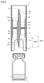
- FIG. 2 is a cross-sectional view of the transfer needle of FIG. 2 as viewed from the direction of the arrow along line III-III. It is sectional drawing which shows the 1st state of the transfer needle which concerns on one Embodiment of this invention, and the liquid containing container. It is sectional drawing which shows the 2nd state of the transfer needle which concerns on one Embodiment of this invention, and the liquid containing container.
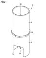
- FIG. 1 is a perspective view showing a transfer needle according to an embodiment of the present invention.
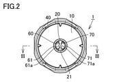
- FIG. 2 is a bottom view of the transfer needle according to the embodiment of the present invention as viewed from the first hollow needle side.
- FIG. 3 is a cross-sectional view of the transfer needle of FIG. 2 as viewed from the direction of the arrow along line III-III.
- the cross section of the liquid storage container is also shown together with the cross section of the transfer needle.
- the transfer needle 1 includes a base 10, at least one first hollow needle 20, at least one second hollow needle 30, and a first fitting.
- a joint portion 40 and a second fitting portion 50 are provided.
- the transfer needle 1 is punctured into a liquid storage container 2 that stores the liquid L and a drug storage container (not shown in FIGS. 1 to 3) that stores the drug.
- the transfer needle 1 is made of, for example, a resin.
- the liquid storage container 2 and the drug storage container are, for example, vials having a container body and a stopper portion for sealing the mouth portion of the container body.
- the stopper is made of rubber such as butyl rubber. Since a recess is formed on the inner surface side of the stopper portion of the liquid storage container 2, a small amount of liquid may adhere to the inner surface side.
- the base 10 is located substantially in the center of the transfer needle 1.
- the base 10 has a substantially disk-shaped outer shape.
- the first hollow needle 20 protrudes from the base 10 and can puncture the liquid storage container 2.
- the transfer needle 1 according to the present embodiment includes only one first hollow needle 20.
- the first hollow needle 20 projects from the center of the base 10 when viewed from the axial direction of the central axis of the base 10.
- the first hollow needle 20 projects parallel to the axial direction of the central axis of the base 10.
- the first hollow needle 20 is punctured into the liquid storage container 2 so as to penetrate the stopper portion of the liquid storage container 2.
- the first hollow needle 20 has a first tip portion 21 located at the tip of the first hollow needle 20 in the protruding direction.
- the second hollow needle 30 protrudes from the side of the base 10 opposite to the first hollow needle 20 side and can puncture the drug storage container.
- the transfer needle 1 according to the present embodiment includes only one second hollow needle 30.
- the second hollow needle 30 projects from the center of the base 10 when viewed from the axial direction of the central axis of the base 10.
- the second hollow needle 30 projects parallel to the axial direction of the central axis of the base 10.
- the drug containing container is a vial
- the second hollow needle 30 is punctured into the drug containing container so as to penetrate the stopper of the drug containing container.
- the second hollow needle 30 has a second tip portion 31 located at the tip of the second hollow needle 30 in the protruding direction.
- the first fitting portion 40 extends from the first hollow needle 20 side of the base 10 and can be fitted with the liquid storage container 2. Specifically, the first fitting portion 40 extends parallel to the axial direction of the central axis from the radial end portion of the central axis of the base portion 10 on the first hollow needle 20 side of the base portion 10.
- the first fitting portion 40 has a cylindrical outer shape centered on the first hollow needle 20. That is, when viewed from the axial direction of the central axis of the base portion 10, the first fitting portion 40 is located at the radial end of the central axis of the base portion 10 along the circumferential direction of the central axis.
- the second fitting portion 50 extends from the second hollow needle 30 side of the base 10 and can be fitted with the drug storage container. Specifically, the second fitting portion 50 extends parallel to the axial direction of the central axis from the radial end portion of the central axis of the base portion 10 on the second hollow needle 30 side of the base portion 10.
- the second fitting portion 50 has a cylindrical outer shape centered on the second hollow needle 30. That is, when viewed from the axial direction of the central axis of the base portion 10, the second fitting portion 50 is located at the radial end of the central axis of the base portion 10 along the circumferential direction of the central axis.
- the transfer needle 1 has a first through hole 60 through which air can flow inside the base 10, the first hollow needle 20, and the second hollow needle 30, and the base 10, the first hollow needle 20, and the second hollow needle 30.
- a second through hole 70 through which the liquid L can flow is formed inside the inside.
- the first through hole 60 extends parallel to the axial direction of the central axis of the base 10.
- the first through hole 60 is positioned so as not to overlap the central axis of the base 10, the central axis of the first hollow needle 20, and the central axis of the second hollow needle 30.
- the first through hole 60 has a first hollow needle side first opening end 61 located on the first tip portion 21 side and a second hollow needle side first opening end 62 located on the second tip portion 31 side. is doing.
- the first open end 61 on the first hollow needle side is located closer to the base 10 than the first tip 21.
- the first open end 61 on the first hollow needle side is positioned so as to intersect diagonally with respect to the protruding direction of the first hollow needle 20.
- the end portion 61a on the first tip portion 21 side of the first hollow needle side first opening end 61 is located on the radial center side of the central axis when viewed from the axial direction of the central axis of the base portion 10.
- the first opening end 62 on the second hollow needle side is located closer to the base 10 than the second tip 31.
- the first opening end 62 on the second hollow needle side is positioned so as to intersect diagonally with respect to the protruding direction of the second hollow needle 30.
- the end portion 62a on the side of the second tip portion 31 of the first opening end 62 on the second hollow needle side is located on the radial center side of the central axis when viewed from the axial direction of the central axis of the base portion 10.
- the second through hole 70 extends parallel to the axial direction of the central axis of the base 10.
- the second through hole 70 is positioned so as not to overlap the central axis of the base 10, the central axis of the first hollow needle 20, and the central axis of the second hollow needle 30.
- the second through hole 70 is located symmetrically with respect to the first through hole 60 with respect to the central axis when viewed from the axial direction of the central axis.
- the second through hole 70 has a first hollow needle side second opening end 71 located on the first tip portion 21 side and a second hollow needle side second opening end 72 located on the second tip portion 31 side. is doing.
- the second open end 71 on the first hollow needle side is located on the base 10 side when viewed from the first open end 61 on the first hollow needle side.
- the second open end 71 on the first hollow needle side is positioned so as to intersect diagonally with respect to the protruding direction of the first hollow needle 20.
- the end portion 71a on the first tip portion 21 side of the first hollow needle side second opening end 71 is located on the radial center side of the central axis when viewed from the axial direction of the central axis of the base portion 10.
- the second open end 72 on the second hollow needle side is located on the base 10 side of the second tip 31.
- the second open end 72 on the second hollow needle side is located on the side of the second tip portion 31 when viewed from the first open end 62 on the second hollow needle side.
- the end portion 72a on the side of the second tip portion 31 of the second open end 72 on the second hollow needle side is located on the radial center side of the central axis when viewed from the axial direction of the central axis of the base portion 10.
- the volume of the portion 20P1 of the first hollow needle 20 located on the first tip portion 21 side when viewed from the second opening end 71 on the first hollow needle side is larger than the volume of the first through hole 60. More specifically, of the first hollow needle 20, the portion 20P2 located on the first tip portion 21 side when viewed from the end portion 71a on the first tip portion 21 side of the first hollow needle side second opening end 71. The volume is larger than the volume of the first through hole 60 from the end 61a on the first tip 21 side of the first opening end 61 on the first hollow needle side to the second hollow needle 30 side.
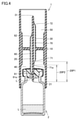
- FIG. 4 is a cross-sectional view showing a first state of the transfer needle and the liquid storage container according to the embodiment of the present invention.
- FIG. 4 it is shown in the same cross-sectional view as in FIG.
- the first hollow needle 20 is punctured into the liquid storage container 2 from above so as to penetrate the stopper portion of the liquid storage container 2.
- the end portion 61a on the first tip portion 21 side of the first hollow needle side first opening end 61 is located in the internal space of the liquid storage container 2.
- the stopper portion of the liquid storage container 2 is in close contact with the first hollow needle 20, the internal space of the liquid storage container 2 is still in a sealed state.
- the liquid L adhering to the inner surface side of the stopper portion of the liquid storage container 2 comes into contact with the end portion 61a.
- FIG. 5 is a cross-sectional view showing a second state of the transfer needle and the liquid storage container according to the embodiment of the present invention.
- the first hollow needle 20 is punctured deeper from the first state into the plug portion of the liquid storage container 2, the entire first opening end 61 on the first hollow needle side becomes the liquid storage container 2. It becomes the second state located in the internal space.
- the internal space of the liquid storage container 2 communicates with the external space through the first through hole 60.
- the liquid L adhering to the inner surface side of the stopper portion of the liquid storage container 2 may adhere to the first opening end 61 on the first hollow needle side.
- the internal space of the liquid storage container 2 becomes positive pressure due to the intrusion of the first hollow needle 20. Therefore, the liquid L adhering to the first opening end 61 on the first hollow needle side is pushed up toward the inside of the first through hole 60 by the positive pressure air in the internal space of the liquid storage container 2. As a result, the liquid L located inside the first through hole 60 closes the first through hole.
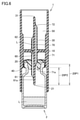
- FIG. 6 is a cross-sectional view showing a third state of the transfer needle and the liquid storage container according to the embodiment of the present invention.
- the third state is that the portion 71a is located in the internal space of the liquid storage container 2.
- the peripheral portion of the end portion 71a of the first hollow needle 20 is in close contact with the stopper portion of the liquid storage container 2. Therefore, the internal space of the liquid storage container 2 does not communicate with the external space through the second through hole 70.
- the first hollow needle 20 further penetrates into the liquid storage container 2. Therefore, the liquid L, which is blocking the inside of the first through hole 60, is further moved to the first opening end 62 on the second hollow needle side of the first through hole 60 by the air in the internal space of the liquid storage container 2. Pushed up towards.
- the volume of the portion 20P1 of the first hollow needle 20 located on the first tip portion 21 side when viewed from the first hollow needle side second opening end 71 is larger than the volume of the first through hole 60. .. More specifically, of the first hollow needle 20, the portion 20P2 located on the first tip portion 21 side when viewed from the end portion 71a on the first tip portion 21 side of the first hollow needle side second opening end 71. The volume is larger than the volume of the first through hole 60, the first opening end 61 on the first hollow needle side, from the end 61a on the first tip 21 side to the second hollow needle 30 side.
- the liquid L blocking the first through hole 60 is abdicated by the air in the internal space of the liquid storage container 2. 2 It is pushed up to the vicinity of the first opening end 62 on the hollow needle side, or discharged from the first opening end 62 on the second hollow needle side.
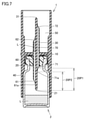
- FIG. 7 is a cross-sectional view showing a fourth state of the transfer needle and the liquid storage container according to the embodiment of the present invention.
- the liquid storage container 2 comes into contact with the base 10 and the second hollow needle side second.
- the entire opening end 71 is in the fourth state located in the internal space of the liquid storage container 2.
- the internal space of the liquid storage container 2 communicates with the external space through the second through hole 70. Therefore, in the fourth state, the first hollow needle 20 penetrates deeper into the internal space of the liquid storage container 2 from the third state, but in the fourth state, the first through hole 60 is closed.
- the position of the liquid L hardly changes from the third state.
- the first open end 61 on the first hollow needle side is positioned so as not to come into contact with the main body of the liquid L contained in the liquid storage container 2 in the fourth state.
- FIG. 8 is a cross-sectional view showing a fifth state of the transfer needle and the liquid storage container according to the embodiment of the present invention.
- the inside of the first through hole 60 may be blocked by the liquid L.
- the liquid L in the first through hole 60 is located near the first opening end 62 on the second hollow needle side. Therefore, by swinging the transfer needle 1 while puncturing the liquid storage container 2, the liquid L in the first through hole 60 becomes the second due to the elastic vibration of the air in the liquid storage container 2. It is easily discharged from the first opening end 62 on the hollow needle side. As a result, air can enter the internal space of the liquid storage container 2 through the first through hole 60, so that the internal space inside the liquid storage container 2 is suppressed from becoming negative pressure.
- the liquid L is smoothly transferred from the liquid storage container 2 punctured by the transfer needle 1 to the drug storage container 3 through the second through hole 70.
- the drug solution generated by dissolving the drug in the liquid L in the drug storage container 3 may be sucked with a syringe.
- the drug solution in the drug storage container 3 is sucked by a syringe, the drug solution is sucked from the inside of the drug storage container 3 in a state where the transfer needle 1 (second hollow needle 30) is punctured through the first through hole 60. May be good.
- a tubular adapter is connected to the first hollow needle 20 from one side.
- the tip of the syringe is connected to the other side of the tubular adapter.
- a sintered filter may be located inside the adapter to prevent foreign matter from entering the syringe.
- the transfer needle 1 is punctured by the liquid storage container 2 for storing the liquid L and the drug storage container 3 for storing the drug.
- the transfer needle 1 includes a base 10, at least one first hollow needle 20, and at least one second hollow needle 30.
- the first hollow needle 20 protrudes from the base 10 and can puncture the liquid storage container 2.
- the first hollow needle 20 has a first tip portion 21 located at the tip of the first hollow needle 20 in the protruding direction.
- the second hollow needle 30 protrudes from the side of the base 10 opposite to the first hollow needle 20 side and can puncture the drug storage container 3.
- the transfer needle 1 has a first through hole 60 through which air can flow inside the base 10, the first hollow needle 20, and the second hollow needle 30, and the base 10, the first hollow needle 20, and the second hollow needle 30.
- a second through hole 70 through which the liquid L can flow is formed inside the inside.
- the first through hole 60 has a first open end 61 on the first hollow needle side located on the first tip 21 side.
- the second through hole 70 has a first hollow needle side second opening end 71 located on the first tip portion 21 side and on the base 10 side when viewed from the first hollow needle side first opening end 61. is doing.
- the volume of the portion 20P1 of the first hollow needle 20 located on the first tip portion 21 side when viewed from the second opening end 71 on the first hollow needle side is larger than the volume of the first through hole 60.
- the first through hole 60 through which air can flow is suppressed from being blocked by the liquid L, and the liquid L is punctured from the first hollow needle 20 through the second through hole 70. Can be transferred smoothly.
- the first open end 61 on the first hollow needle side is positioned so as to intersect diagonally with respect to the protruding direction of the first hollow needle 20.
- the second open end 71 on the first hollow needle side is positioned so as to intersect diagonally with respect to the protruding direction of the first hollow needle 20.
- the volume of the portion 20P2 located on the first tip portion 21 side when viewed from the end portion 71a on the first tip portion 21 side of the first hollow needle side second opening end 71 is the volume of the first penetration.
- the volume of the hole 60 is larger than the volume from the end 61a on the first tip 21 side of the first opening end 61 on the first hollow needle side to the second hollow needle 30 side.
- the second hollow needle 30 has a second tip portion 31 located at the tip of the second hollow needle 30 in the protruding direction.
- the first through hole 60 further has a second hollow needle-side first opening end 62 located on the second tip 31 side.
- the second through hole 70 is located on the second tip portion 31 side and is located on the second tip portion 31 side when viewed from the second hollow needle side first opening end 62. It also has 72.
- the transfer needle 1 further includes a first fitting portion 40 and a second fitting portion 50.
- the first fitting portion 40 extends from the first hollow needle 20 side of the base portion 10 and can be fitted with the liquid storage container 2.
- the first fitting portion 40 has a cylindrical outer shape centered on the first hollow needle 20.
- the second fitting portion 50 extends from the second hollow needle 30 side of the base portion 10 and can be fitted with the drug storage container.
- the second fitting portion 50 has a cylindrical outer shape centered on the second hollow needle 30.
- the transfer needle 1 can be easily fitted to these containers.
- the first hollow needle 20 and the second hollow needle 30 can be easily punctured in these containers.
Landscapes
- Engineering & Computer Science (AREA)
- Mechanical Engineering (AREA)
- Health & Medical Sciences (AREA)
- Pharmacology & Pharmacy (AREA)
- Life Sciences & Earth Sciences (AREA)
- Animal Behavior & Ethology (AREA)
- General Health & Medical Sciences (AREA)
- Public Health (AREA)
- Veterinary Medicine (AREA)
- Medical Preparation Storing Or Oral Administration Devices (AREA)
- Closures For Containers (AREA)
Abstract
トランスファーニードル(1)には、基部(10)、第1中空針(20)および第2中空針(30)の内部を空気が通流可能な第1貫通孔(60)と、基部(10)、第1中空針(20)および第2中空針(30)の内部を液体(L)が通流可能な第2貫通孔(70)とが形成されている。第1貫通孔(60)は、第1先端部(21)側に位置する第1中空針側第1開口端(61)を有している。第2貫通孔(70)は、第1先端部(21)側に位置し、かつ、第1中空針側第1開口端(61)から見て基部(10)側に位置する第1中空針側第2開口端(71)を有している。第1中空針(20)のうち第1中空針側第2開口端(71)から見て第1先端部(21)側に位置する部分(20P1)の体積は、第1貫通孔(60)の容積より大きい。
Description
本発明は、トランスファーニードルに関する。
トランスファーニードルの構成を開示した先行文献として、実公平7-53625号公報(特許文献1)がある。特許文献1に記載されたトランスファーニードルは、通気用と通液用の2穴が平行に配されたニードル本体を具備する。ニードルの本体上部はバイアルの口部のゴム栓に刺入貫通される。
液体を収容するバイアルなどの液体収容容器の内面には、液体本体とは離れた位置に少量の液体が付着している場合がある。液体収容容器がたとえばバイアルである場合には、上記の少量の液体は、ゴム栓の内面側の凹部に位置する。従来のトランスファーニードルにおいては、中空針を液体収容容器に挿通する際に、上記の少量の液体が、中空針に付着し、さらには、通気用の貫通孔に入り込む場合がある。この場合、トランスファーニードルによって液体収容容器から液体を移注するときに、上記の少量の液体によって通気用の貫通孔が閉塞して、液体が液体用の貫通孔を滑らかに流れない。
本発明の上記の問題点に鑑みてなされたものであり、空気が通流可能な貫通孔が液体で閉塞することを抑制して、液体収容容器に収容された液体を滑らかに移注できる、トランスファーニードルを提供することを目的とする。
本発明に基づくトランスファーニードルは、液体を収容する液体収容容器および薬剤を収容する薬剤収容容器に穿刺される。トランスファーニードルは、基部と、少なくとも1つの第1中空針と、少なくとも1つの第2中空針とを備えている。第1中空針は、基部から突出して液体収容容器に穿刺可能である。第1中空針は、第1中空針の突出方向先端に位置する第1先端部を有している。第2中空針は、基部の第1中空針側とは反対側から突出して薬剤収容容器に穿刺可能である。トランスファーニードルには、基部、第1中空針および第2中空針の内部を空気が通流可能な第1貫通孔と、基部、第1中空針および第2中空針の内部を液体が通流可能な第2貫通孔とが形成されている。第1貫通孔は、第1先端部側に位置する第1中空針側第1開口端を有している。第2貫通孔は、第1先端部側に位置し、かつ、第1中空針側第1開口端から見て基部側に位置する第1中空針側第2開口端を有している。第1中空針のうち第1中空針側第2開口端から見て第1先端部側に位置する部分の体積は、第1貫通孔の容積より大きい。
本発明の一形態においては、第1中空針側第1開口端は、第1中空針の突出方向に対して斜めに交差するように位置している。第1中空針側第2開口端は、第1中空針の突出方向に対して斜めに交差するように位置している。第1中空針のうち、第1中空針側第2開口端の第1先端部側の端部から見て第1先端部側に位置する部分の体積は、第1貫通孔の、第1中空針側第1開口端の第1先端部側の端部から第2中空針側にかけての容積より大きい。
本発明の一形態においては、第2中空針は、第2中空針の突出方向先端に位置する第2先端部を有している。第1貫通孔は、第2先端部側に位置する第2中空針側第1開口端をさらに有している。第2貫通孔は、第2先端部側に位置し、かつ、第2中空針側第1開口端から見て第2先端部側に位置する第2中空針側第2開口端をさらに有している。
本発明の一形態においては、トランスファーニードルが、第1嵌合部と、第2嵌合部とをさらに備えている。第1嵌合部は、基部の第1中空針側から延びて、液体収容容器と嵌合可能である。第1嵌合部は、第1中空針を中心とする筒状の外形を有している。第2嵌合部は、基部の第2中空針側から延びて、薬剤収容容器と嵌合可能である。第2嵌合部は、第2中空針を中心とする筒状の外形を有している。
本発明によれば、空気が通流可能な貫通孔が液体で閉塞することを抑制して、液体収容容器に収容された液体を滑らかに移注できる。
以下、本発明の一実施形態に係るトランスファーニードルについて図を参照して説明する。以下の実施形態の説明においては、図中の同一または相当部分には同一符号を付して、その説明は繰り返さない。
図1は、本発明の一実施形態に係るトランスファーニードルを示す斜視図である。図2は、本発明の一実施形態に係るトランスファーニードルを第1中空針側から見た底面図である。図3は、図2のトランスファーニードルをIII-III線矢印方向から見た断面図である。なお、図3においては、トランスファーニードルの断面ととともに液体収容容器の断面も図示している。
図1から図3に示すように、本発明の一実施形態に係るトランスファーニードル1は、基部10と、少なくとも1つの第1中空針20と、少なくとも1つの第2中空針30と、第1嵌合部40と、第2嵌合部50とを備えている。
トランスファーニードル1は、液体Lを収容する液体収容容器2および薬剤を収容する薬剤収容容器(図1から図3において図示略)に穿刺される。トランスファーニードル1は、たとえば樹脂で形成されている。液体収容容器2および薬剤収容容器は、たとえば、容器本体と、容器本体の口部を封止する栓部とを有する、バイアルである。栓部は、たとえばブチルゴムなどのゴムで形成されている。液体収容容器2の栓部の内面側には、凹部が形成されていることにより、少量の液体が付着している場合がある。
基部10は、トランスファーニードル1の略中央に位置している。基部10は、略円板状の外形を有している。
第1中空針20は、基部10から突出して液体収容容器2に穿刺可能である。本実施形態に係るトランスファーニードル1は、第1中空針20を1つのみ備えている。第1中空針20は、基部10の中心軸の軸方向から見て基部10の中心から突出している。第1中空針20は、基部10の中心軸の軸方向に平行に突出している。液体収容容器2がバイアルである場合、第1中空針20は、液体収容容器2の栓部を貫通するように液体収容容器2に穿刺される。第1中空針20は、第1中空針20の突出方向先端に位置する第1先端部21を有している。
第2中空針30は、基部10の第1中空針20側とは反対側から突出して薬剤収容容器に穿刺可能である。本実施形態に係るトランスファーニードル1は、第2中空針30を1つのみ備えている。第2中空針30は、基部10の中心軸の軸方向から見て基部10の中心から突出している。第2中空針30は、基部10の中心軸の軸方向に平行に突出している。薬剤収容容器がバイアルである場合、第2中空針30は、薬剤収容容器の栓部を貫通するように薬剤収容容器に穿刺される。また、第2中空針30は、第2中空針30の突出方向先端に位置する第2先端部31を有している。
第1嵌合部40は、基部10の第1中空針20側から延びて、液体収容容器2と嵌合可能である。具体的には、第1嵌合部40は、基部10の第1中空針20側において、基部10の中心軸の径方向端部から、中心軸の軸方向に平行に延びている。第1嵌合部40は、第1中空針20を中心とする筒状の外形を有している。すなわち、基部10の中心軸の軸方向から見たときに、第1嵌合部40は、基部10の中心軸の径方向端部において、中心軸の周方向に沿って位置している。
第2嵌合部50は、基部10の第2中空針30側から延びて、薬剤収容容器と嵌合可能である。具体的には、第2嵌合部50は、基部10の第2中空針30側において、基部10の中心軸の径方向端部から、中心軸の軸方向に平行に延びている。第2嵌合部50は、第2中空針30を中心とする筒状の外形を有している。すなわち、基部10の中心軸の軸方向から見たときに、第2嵌合部50は、基部10の中心軸の径方向端部において、中心軸の周方向に沿って位置している。
トランスファーニードル1には、基部10、第1中空針20および第2中空針30の内部を空気が通流可能な第1貫通孔60と、基部10、第1中空針20および第2中空針30の内部を液体Lが通流可能な第2貫通孔70とが形成されている。
第1貫通孔60は、基部10の中心軸の軸方向に平行に延びている。第1貫通孔60は、基部10の中心軸、第1中空針20の中心軸および第2中空針30の中心軸と重ならないように位置している。
第1貫通孔60は、第1先端部21側に位置する第1中空針側第1開口端61と、第2先端部31側に位置する第2中空針側第1開口端62とを有している。
第1中空針側第1開口端61は、第1先端部21より基部10側に位置している。第1中空針側第1開口端61は、第1中空針20の突出方向に対して斜めに交差するように位置している。第1中空針側第1開口端61の第1先端部21側の端部61aは、基部10の中心軸の軸方向から見たときに上記中心軸の径方向中心側に位置している。
第2中空針側第1開口端62は、第2先端部31より基部10側に位置している。第2中空針側第1開口端62は、第2中空針30の突出方向に対して斜めに交差するように位置している。第2中空針側第1開口端62の第2先端部31側の端部62aは、基部10の中心軸の軸方向から見たときに上記中心軸の径方向中心側に位置している。
第2貫通孔70は、基部10の中心軸の軸方向に平行に延びている。第2貫通孔70は、基部10の中心軸、第1中空針20の中心軸および第2中空針30の中心軸と重ならないように位置している。第2貫通孔70は、上記中心軸の軸方向から見て、当該中心軸に関して第1貫通孔60と対称に位置している。
第2貫通孔70は、第1先端部21側に位置する第1中空針側第2開口端71と、第2先端部31側に位置する第2中空針側第2開口端72とを有している。
第1中空針側第2開口端71は、第1中空針側第1開口端61から見て基部10側に位置している。第1中空針側第2開口端71は、第1中空針20の突出方向に対して斜めに交差するように位置している。第1中空針側第2開口端71の第1先端部21側の端部71aは、基部10の中心軸の軸方向から見たときに上記中心軸の径方向中心側に位置している。
第2中空針側第2開口端72は、第2先端部31より基部10側に位置している。第2中空針側第2開口端72は、第2中空針側第1開口端62から見て第2先端部31側に位置している。第2中空針側第2開口端72の第2先端部31側の端部72aは、基部10の中心軸の軸方向から見たときに上記中心軸の径方向中心側に位置している。
第1中空針20のうち第1中空針側第2開口端71から見て第1先端部21側に位置する部分20P1の体積は、第1貫通孔60の容積より大きい。より具体的には、第1中空針20のうち、第1中空針側第2開口端71の第1先端部21側の端部71aから見て第1先端部21側に位置する部分20P2の体積は、第1貫通孔60の、第1中空針側第1開口端61の第1先端部21側の端部61aから第2中空針30側にかけての容積より大きい。
以下、本発明の一実施形態に係るトランスファーニードル1に穿刺された液体収容容器2から、液体Lを移注する方法について説明する。
図4は、本発明の一実施形態に係るトランスファーニードルの第1の状態と液体収容容器とを示す断面図である。なお、図4以降の図においては、図3と同様の断面視にて図示している。
図4に示すように、液体収容容器2の栓部を貫通するように第1中空針20を液体収容容器2に上方から穿刺する。図4に示した穿刺開始直後である第1の状態においては、第1中空針側第1開口端61の第1先端部21側の端部61aが液体収容容器2の内部空間に位置しているが、液体収容容器2の栓部が第1中空針20と密着している状態であるため、液体収容容器2の内部空間は、未だ密閉された状態である。また、第1の状態においては、液体収容容器2の栓部の内面側に付着した液体Lが上記端部61aと接触する。
図5は、本発明の一実施形態に係るトランスファーニードルの第2の状態と液体収容容器とを示す断面図である。図5に示すように、第1の状態からさらに深く第1中空針20を液体収容容器2の栓部に穿刺すると、第1中空針側第1開口端61の全体が、液体収容容器2の内部空間に位置する第2の状態となる。第1の状態から第2の状態に移行する間に、液体収容容器2の内部空間は、第1貫通孔60を介して外部空間と連通する。しかしながら、当該第2の状態においては、液体収容容器2の栓部の内面側に付着した液体Lが第1中空針側第1開口端61に付着する場合がある。一方で、液体収容容器2の内部空間は、第1中空針20の侵入により陽圧になっている。このため、第1中空針側第1開口端61に付着した液体Lは、液体収容容器2の内部空間内の陽圧の空気によって、第1貫通孔60の内部に向かって押し上げられる。結果として、第1貫通孔60の内部に位置する液体Lが第1貫通孔を閉塞させる。
図6は、本発明の一実施形態に係るトランスファーニードルの第3の状態と液体収容容器とを示す断面図である。図6に示すように、第2の状態からさらに深く第1中空針20を液体収容容器2の栓部に穿刺すると、第1中空針側第2開口端71の第1先端部21側の端部71aが液体収容容器2の内部空間に位置する第3の状態となる。第3の状態においては、第1中空針20の端部71aの周辺部分が液体収容容器2の栓部と密着している。このため、液体収容容器2の内部空間は、第2貫通孔70を介しては外部空間と連通していない。一方で、第2の状態と比較して第1中空針20がさらに液体収容容器2の内部に侵入している。このため、第1貫通孔60の内部を閉塞させているを液体Lは、さらに液体収容容器2の内部空間内の空気によって、第1貫通孔60の第2中空針側第1開口端62に向かって押し上げられる。
本実施形態においては、第1中空針20のうち第1中空針側第2開口端71から見て第1先端部21側に位置する部分20P1の体積は、第1貫通孔60の容積より大きい。より具体的には、第1中空針20のうち、第1中空針側第2開口端71の第1先端部21側の端部71aから見て第1先端部21側に位置する部分20P2の体積は、第1貫通孔60の、第1中空針側第1開口端61の、第1先端部21側の端部61aから第2中空針30側にかけての容積より大きい。このように上記部分20P1および上記部分20P2の体積が十分大きいため、本実施形態においては、第1貫通孔60を閉塞させている液体Lは、液体収容容器2の内部空間内の空気によって、第2中空針側第1開口端62近傍まで押し上げられる、または、第2中空針側第1開口端62から排出される。
図7は、本発明の一実施形態に係るトランスファーニードルの第4の状態と液体収容容器とを示す断面図である。図7に示すように、第3の状態からさらに深く第1中空針20を液体収容容器2の栓部に穿刺すると、液体収容容器2が基部10に当接するとともに、第1中空針側第2開口端71の全体が、液体収容容器2の内部空間に位置する第4の状態となる。第3の状態から第4の状態に移行する間に、液体収容容器2の内部空間は、第2貫通孔70を介して外部空間と連通する。このため、第4の状態においては、第3の状態からさらに深く第1中空針20が液体収容容器2の内部空間に侵入するが、第4の状態において第1貫通孔60を閉塞させている液体Lの位置は、第3の状態からほとんど変化しない。なお、図7に示すように、第1中空針側第1開口端61は、第4の状態において、液体収容容器2に収容された液体Lの本体に接触しないように位置している。
図8は、本発明の一実施形態に係るトランスファーニードルの第5の状態と液体収容容器とを示す断面図である。図7に示した第4の状態のトランスファーニードル1の第2中空針30を、逆さにした(栓部が下方に向いた)状態の薬剤収容容器3に穿刺した後、図8に示すように、第2中空針30が第1中空針20の下方に位置するように、トランスファーニードル1をひっくり返す。これにより、液体収容容器2に収容された液体Lは、第2貫通孔70を通って、第2中空針30が穿刺された薬剤収容容器3に移注される。なお、図8に示すように、第1中空針側第1開口端61は、トランスファーニードル1をひっくり返した第5の状態において、液体収容容器2に収容された液体Lの本体に埋没しないように位置している。
このとき、上述したように第1貫通孔60内が液体Lによって閉塞している場合がある。しかしながら、本実施形態に係るトランスファーニードル1においては、第1貫通孔60内の液体Lが第2中空針側第1開口端62近傍に位置している。このため、液体収容容器2に穿刺している状態のままトランスファーニードル1を揺動させることで、液体収容容器2内の空気の弾性振動により、第1貫通孔60内の液体Lは、第2中空針側第1開口端62から容易に排出される。ひいては、液体収容容器2の内部空間に第1貫通孔60を通って空気が侵入可能となるため、液体収容容器2内の内部空間が負圧になることが抑制される。
以上の方法により、本実施形態においては、トランスファーニードル1に穿刺された液体収容容器2から、第2貫通孔70を通って液体Lが滑らかに薬剤収容容器3に移注される。
なお、薬剤収容容器3内で薬剤が液体Lに溶解することで生成された薬液は、シリンジで吸引してもよい。薬剤収容容器3内の薬液をシリンジによって吸引する場合は、トランスファーニードル1(第2中空針30)が穿刺した状態の薬剤収容容器3内から、第1貫通孔60を介して薬液が吸引されてもよい。第1貫通孔60を介して薬液を吸引する場合には、たとえば、第1中空針20に、筒状のアダプタが一方側から接続される。筒状のアダプタの他方側には、シリンジの先端部が接続される。アダプタの内部には、シリンジ内に異物が混入するのを抑制するための焼結フィルターが位置してもよい。
上述のように、本発明の一実施形態に係るトランスファーニードル1は、液体Lを収容する液体収容容器2および薬剤を収容する薬剤収容容器3に穿刺される。トランスファーニードル1は、基部10と、少なくとも1つの第1中空針20と、少なくとも1つの第2中空針30とを備えている。第1中空針20は、基部10から突出して液体収容容器2に穿刺可能である。第1中空針20は、第1中空針20の突出方向先端に位置する第1先端部21を有している。第2中空針30は、基部10の第1中空針20側とは反対側から突出して薬剤収容容器3に穿刺可能である。トランスファーニードル1には、基部10、第1中空針20および第2中空針30の内部を空気が通流可能な第1貫通孔60と、基部10、第1中空針20および第2中空針30の内部を液体Lが通流可能な第2貫通孔70とが形成されている。第1貫通孔60は、第1先端部21側に位置する第1中空針側第1開口端61を有している。第2貫通孔70は、第1先端部21側に位置し、かつ、第1中空針側第1開口端61から見て基部10側に位置する第1中空針側第2開口端71を有している。第1中空針20のうち第1中空針側第2開口端71から見て第1先端部21側に位置する部分20P1の体積は、第1貫通孔60の容積より大きい。
これにより、空気を通流可能な第1貫通孔60が液体Lで閉塞することを抑制して、液体Lを、第1中空針20に穿刺した液体収容容器から第2貫通孔70を介して滑らかに移注できる。
本実施形態においては、第1中空針側第1開口端61は、第1中空針20の突出方向に対して斜めに交差するように位置している。第1中空針側第2開口端71は、第1中空針20の突出方向に対して斜めに交差するように位置している。第1中空針20のうち、第1中空針側第2開口端71の第1先端部21側の端部71aから見て第1先端部21側に位置する部分20P2の体積は、第1貫通孔60の、第1中空針側第1開口端61の第1先端部21側の端部61aから第2中空針30側にかけての容積より大きい。
これにより、空気を通流可能な第1貫通孔60が液体Lで閉塞することをさらに抑制できる。
本実施形態においては、第2中空針30は、第2中空針30の突出方向先端に位置する第2先端部31を有している。第1貫通孔60は、第2先端部31側に位置する第2中空針側第1開口端62をさらに有している。第2貫通孔70は、第2先端部31側に位置し、かつ、第2中空針側第1開口端62から見て第2先端部31側に位置する第2中空針側第2開口端72をさらに有している。
これにより、第2中空針側第1開口端62から排出された液体Lの残液が、第2中空針側第2開口端72に付着することを抑制できる。
本実施形態においては、トランスファーニードル1が、第1嵌合部40と、第2嵌合部50とをさらに備えている。第1嵌合部40は、基部10の第1中空針20側から延びて、液体収容容器2と嵌合可能である。第1嵌合部40は、第1中空針20を中心とする筒状の外形を有している。第2嵌合部50は、基部10の第2中空針30側から延びて、薬剤収容容器と嵌合可能である。第2嵌合部50は、第2中空針30を中心とする筒状の外形を有している。
これにより、液体収容容器2および薬剤収容容器がバイアルなどの略円筒状の外形を有している場合には、これらの容器をトランスファーニードル1を容易に嵌合させることができる。ひいては、これらの容器に第1中空針20および第2中空針30を容易に穿刺できる。
今回開示された実施形態はすべての点で例示であって制限的なものではないと考えられるべきである。本発明の範囲は上記した説明ではなくて請求の範囲によって示され、請求の範囲と均等の意味および範囲内でのすべての変更が含まれることが意図される。
1 トランスファーニードル、2 液体収容容器、3 薬剤収容容器、10 基部、20 第1中空針、21 第1先端部、30 第2中空針、31 第2先端部、40 第1嵌合部、50 第2嵌合部、60 第1貫通孔、61 第1中空針側第1開口端、62 第2中空針側第1開口端、70 第2貫通孔、71 第1中空針側第2開口端、72 第2中空針側第2開口端、L 液体。
Claims (4)
- 液体を収容する液体収容容器および薬剤を収容する薬剤収容容器に穿刺されるトランスファーニードルであって、
前記トランスファーニードルは、
基部と、
前記基部から突出して前記液体収容容器に穿刺可能な少なくとも1つの第1中空針と、
前記基部の前記第1中空針側とは反対側から突出して前記薬剤収容容器に穿刺可能な少なくとも1つの第2中空針とを備え、
前記第1中空針は、前記第1中空針の突出方向先端に位置する第1先端部を有し、
前記トランスファーニードルには、前記基部、前記第1中空針および前記第2中空針の内部を空気が通流可能な第1貫通孔と、前記基部、前記第1中空針および前記第2中空針の内部を液体が通流可能な第2貫通孔とが形成されており、
前記第1貫通孔は、前記第1先端部側に位置する第1中空針側第1開口端を有し、
前記第2貫通孔は、前記第1先端部側に位置し、かつ、前記第1中空針側第1開口端から見て前記基部側に位置する第1中空針側第2開口端を有し、
前記第1中空針のうち前記第1中空針側第2開口端から見て前記第1先端部側に位置する部分の体積は、前記第1貫通孔の容積より大きい、トランスファーニードル。 - 前記第1中空針側第1開口端は、前記第1中空針の突出方向に対して斜めに交差するように位置しており、
前記第1中空針側第2開口端は、前記第1中空針の突出方向に対して斜めに交差するように位置しており、
前記第1中空針のうち、前記第1中空針側第2開口端の前記第1先端部側の端部から見て前記第1先端部側に位置する部分の体積は、前記第1貫通孔の、前記第1中空針側第1開口端の前記第1先端部側の端部から前記第2中空針側にかけての容積より大きい、請求項1に記載のトランスファーニードル。 - 前記第2中空針は、前記第2中空針の突出方向先端に位置する第2先端部を有し、
前記第1貫通孔は、前記第2先端部側に位置する第2中空針側第1開口端をさらに有し、
前記第2貫通孔は、前記第2先端部側に位置し、かつ、前記第2中空針側第1開口端から見て前記第2先端部側に位置する第2中空針側第2開口端をさらに有する、請求項1または請求項2に記載のトランスファーニードル。 - 前記基部の前記第1中空針側から延びて、前記液体収容容器と嵌合可能な第1嵌合部と、
前記基部の前記第2中空針側から延びて、前記薬剤収容容器と嵌合可能な第2嵌合部とをさらに備え、
前記第1嵌合部は、前記第1中空針を中心とする筒状の外形を有しており、
前記第2嵌合部は、前記第2中空針を中心とする筒状の外形を有している、請求項1から請求項3のいずれか1項に記載のトランスファーニードル。
Applications Claiming Priority (2)
| Application Number | Priority Date | Filing Date | Title |
|---|---|---|---|
| JP2020151101A JP7400669B2 (ja) | 2020-09-09 | 2020-09-09 | トランスファーニードル |
| JP2020-151101 | 2020-09-09 |
Publications (1)
| Publication Number | Publication Date |
|---|---|
| WO2022054863A1 true WO2022054863A1 (ja) | 2022-03-17 |
Family
ID=80631615
Family Applications (1)
| Application Number | Title | Priority Date | Filing Date |
|---|---|---|---|
| PCT/JP2021/033123 Ceased WO2022054863A1 (ja) | 2020-09-09 | 2021-09-09 | トランスファーニードル |
Country Status (2)
| Country | Link |
|---|---|
| JP (1) | JP7400669B2 (ja) |
| WO (1) | WO2022054863A1 (ja) |
Citations (2)
| Publication number | Priority date | Publication date | Assignee | Title |
|---|---|---|---|---|
| JPS4951788A (ja) * | 1972-09-21 | 1974-05-20 | ||
| JP2012217729A (ja) * | 2011-04-12 | 2012-11-12 | Nipro Corp | 薬剤調製器具 |
Family Cites Families (1)
| Publication number | Priority date | Publication date | Assignee | Title |
|---|---|---|---|---|
| FR2815328B1 (fr) | 2000-10-17 | 2002-12-20 | Biodome | Dispositif de connexion entre un recipient et un contenant et ensemble pret a l'emploi comprenant un tel dispositif |
-
2020
- 2020-09-09 JP JP2020151101A patent/JP7400669B2/ja active Active
-
2021
- 2021-09-09 WO PCT/JP2021/033123 patent/WO2022054863A1/ja not_active Ceased
Patent Citations (2)
| Publication number | Priority date | Publication date | Assignee | Title |
|---|---|---|---|---|
| JPS4951788A (ja) * | 1972-09-21 | 1974-05-20 | ||
| JP2012217729A (ja) * | 2011-04-12 | 2012-11-12 | Nipro Corp | 薬剤調製器具 |
Also Published As
| Publication number | Publication date |
|---|---|
| JP2022045487A (ja) | 2022-03-22 |
| JP7400669B2 (ja) | 2023-12-19 |
Similar Documents
| Publication | Publication Date | Title |
|---|---|---|
| JP4763968B2 (ja) | 移送装置 | |
| US11344475B2 (en) | Connection equipment and equipment connector | |
| JP6007183B2 (ja) | 医療用容器 | |
| WO2010061742A1 (ja) | コネクタ | |
| JP2004267776A (ja) | 医用流体のための移送装置 | |
| WO2013179596A1 (ja) | 曝露防止用キャップ | |
| JPH08238324A (ja) | 複数薬液混注具 | |
| US20150174337A1 (en) | Elastic cap and syringe assembly therewith | |
| KR100198363B1 (ko) | 약제용기 | |
| WO2012133131A1 (ja) | コネクタ | |
| EP3791850A1 (en) | Medical hollow needle and method for using the same | |
| JP2022045487A (ja) | トランスファーニードル | |
| JP2018510715A (ja) | 薬剤バイアルストッパー | |
| JPH0666682U (ja) | 注射針 | |
| US11090442B2 (en) | Syringe cap, syringe assembly, and prefilled syringe | |
| JP4479201B2 (ja) | 医療容器用キャップ | |
| JP2021115450A (ja) | トランスファーニードル | |
| JP3616144B2 (ja) | 連通手段付き薬液容器 | |
| JP3114128U (ja) | 注射器 | |
| JP5434084B2 (ja) | コネクタ | |
| CN213490571U (zh) | 用于小瓶的适配器 | |
| JP4473597B2 (ja) | 混注部材及び医療用具 | |
| JP5699239B1 (ja) | 注射器用容器 | |
| JP2005342494A (ja) | プレフィルドシリンジ | |
| JP2005245931A (ja) | 医療用針及び薬液注入装置 |
Legal Events
| Date | Code | Title | Description |
|---|---|---|---|
| 121 | Ep: the epo has been informed by wipo that ep was designated in this application |
Ref document number: 21866821 Country of ref document: EP Kind code of ref document: A1 |
|
| NENP | Non-entry into the national phase |
Ref country code: DE |
|
| 122 | Ep: pct application non-entry in european phase |
Ref document number: 21866821 Country of ref document: EP Kind code of ref document: A1 |