WO2022054597A1 - 電解銅箔、リチウムイオン二次電池用負極、及びリチウムイオン二次電池 - Google Patents
電解銅箔、リチウムイオン二次電池用負極、及びリチウムイオン二次電池 Download PDFInfo
- Publication number
- WO2022054597A1 WO2022054597A1 PCT/JP2021/031362 JP2021031362W WO2022054597A1 WO 2022054597 A1 WO2022054597 A1 WO 2022054597A1 JP 2021031362 W JP2021031362 W JP 2021031362W WO 2022054597 A1 WO2022054597 A1 WO 2022054597A1
- Authority
- WO
- WIPO (PCT)
- Prior art keywords
- copper foil
- electrolytic copper
- lithium ion
- ion secondary
- electrolytic
- Prior art date
- Legal status (The legal status is an assumption and is not a legal conclusion. Google has not performed a legal analysis and makes no representation as to the accuracy of the status listed.)
- Ceased
Links
Images
Classifications
-
- C—CHEMISTRY; METALLURGY
- C25—ELECTROLYTIC OR ELECTROPHORETIC PROCESSES; APPARATUS THEREFOR
- C25D—PROCESSES FOR THE ELECTROLYTIC OR ELECTROPHORETIC PRODUCTION OF COATINGS; ELECTROFORMING; APPARATUS THEREFOR
- C25D1/00—Electroforming
- C25D1/04—Wires; Strips; Foils
-
- C—CHEMISTRY; METALLURGY
- C25—ELECTROLYTIC OR ELECTROPHORETIC PROCESSES; APPARATUS THEREFOR
- C25D—PROCESSES FOR THE ELECTROLYTIC OR ELECTROPHORETIC PRODUCTION OF COATINGS; ELECTROFORMING; APPARATUS THEREFOR
- C25D1/00—Electroforming
-
- C—CHEMISTRY; METALLURGY
- C25—ELECTROLYTIC OR ELECTROPHORETIC PROCESSES; APPARATUS THEREFOR
- C25D—PROCESSES FOR THE ELECTROLYTIC OR ELECTROPHORETIC PRODUCTION OF COATINGS; ELECTROFORMING; APPARATUS THEREFOR
- C25D3/00—Electroplating: Baths therefor
- C25D3/02—Electroplating: Baths therefor from solutions
- C25D3/38—Electroplating: Baths therefor from solutions of copper
-
- H—ELECTRICITY
- H01—ELECTRIC ELEMENTS
- H01M—PROCESSES OR MEANS, e.g. BATTERIES, FOR THE DIRECT CONVERSION OF CHEMICAL ENERGY INTO ELECTRICAL ENERGY
- H01M4/00—Electrodes
- H01M4/02—Electrodes composed of, or comprising, active material
- H01M4/13—Electrodes for accumulators with non-aqueous electrolyte, e.g. for lithium-accumulators; Processes of manufacture thereof
-
- H—ELECTRICITY
- H01—ELECTRIC ELEMENTS
- H01M—PROCESSES OR MEANS, e.g. BATTERIES, FOR THE DIRECT CONVERSION OF CHEMICAL ENERGY INTO ELECTRICAL ENERGY
- H01M4/00—Electrodes
- H01M4/02—Electrodes composed of, or comprising, active material
- H01M4/64—Carriers or collectors
-
- H—ELECTRICITY
- H01—ELECTRIC ELEMENTS
- H01M—PROCESSES OR MEANS, e.g. BATTERIES, FOR THE DIRECT CONVERSION OF CHEMICAL ENERGY INTO ELECTRICAL ENERGY
- H01M4/00—Electrodes
- H01M4/02—Electrodes composed of, or comprising, active material
- H01M4/64—Carriers or collectors
- H01M4/66—Selection of materials
-
- Y—GENERAL TAGGING OF NEW TECHNOLOGICAL DEVELOPMENTS; GENERAL TAGGING OF CROSS-SECTIONAL TECHNOLOGIES SPANNING OVER SEVERAL SECTIONS OF THE IPC; TECHNICAL SUBJECTS COVERED BY FORMER USPC CROSS-REFERENCE ART COLLECTIONS [XRACs] AND DIGESTS
- Y02—TECHNOLOGIES OR APPLICATIONS FOR MITIGATION OR ADAPTATION AGAINST CLIMATE CHANGE
- Y02E—REDUCTION OF GREENHOUSE GAS [GHG] EMISSIONS, RELATED TO ENERGY GENERATION, TRANSMISSION OR DISTRIBUTION
- Y02E60/00—Enabling technologies; Technologies with a potential or indirect contribution to GHG emissions mitigation
- Y02E60/10—Energy storage using batteries
Definitions
- the present invention relates to an electrolytic copper foil, a negative electrode for a lithium ion secondary battery using the electrolytic copper foil, and a lithium ion secondary battery including the negative electrode for the lithium ion secondary battery.
- a copper foil may be used as a negative electrode current collector of a lithium ion secondary battery, but the copper foil may break due to expansion and contraction of the negative electrode material during charging and discharging of the lithium ion secondary battery.
- the copper foil and the negative electrode material that are in close contact with each other are locally peeled off during charging and discharging, and stress during expansion and contraction is concentrated on the peeled portion, so that the copper foil may break.
- Patent Documents 1 and 2 disclose an electrolytic copper foil that can be used as a negative electrode current collector of a lithium ion secondary battery.
- the electrolytic copper foil disclosed in Patent Documents 1 and 2 may have insufficient mechanical properties and adhesion to the negative electrode material, and therefore may be broken during charging / discharging of the lithium ion secondary battery. ..
- An object of the present invention is to provide an electrolytic copper foil that is less likely to break. Another object of the present invention is to provide a negative electrode for a lithium ion secondary battery and a lithium ion secondary battery in which the negative electrode current collector is less likely to break during charging and discharging.
- the electrolytic copper foil according to one aspect of the present invention has a foil thickness of t (unit: ⁇ m) and is measured by irradiating light with an incident angle of 60 ° along the length direction with respect to the electrolytic precipitation end surface.
- the foil thickness t is 10 or more and 20 or less, and the glossiness Gs.
- the gist is that Gs / t divided by the foil thickness t is 10 or more and 40 or less, and E / t obtained by dividing the elongation E by the foil thickness t is 0.9 or more and 1.8 or less.
- the negative electrode for a lithium ion secondary battery according to another aspect of the present invention includes the electrolytic copper foil according to the above aspect. Further, it is a gist that the lithium ion secondary battery according to another aspect of the present invention includes a negative electrode for a lithium ion secondary battery according to the other aspect.
- the electrolytic copper foil of the present invention is less likely to break. Further, the negative electrode for a lithium ion secondary battery and the lithium ion secondary battery of the present invention are less likely to break in the negative electrode current collector during charging and discharging.
- the electrolytic copper foil according to the embodiment of the present invention has a foil thickness of t (unit: ⁇ m) and is measured by irradiating light with an incident angle of 60 ° along the length direction with respect to the electrolytic precipitation end surface.
- t unit: ⁇ m
- the foil thickness t is 10 or more and 20 or less, and the glossiness.
- Gs / t obtained by dividing Gs by the foil thickness t is 10 or more and 40 or less, and E / t obtained by dividing the elongation E by the foil thickness t is 0.9 or more and 1.8 or less. Due to such a configuration, the electrolytic copper foil of the present embodiment is unlikely to break.
- the electrolytic copper foil of the present embodiment can be used as a negative electrode current collector of a lithium ion secondary battery (mainly a cylindrical lithium ion secondary battery). That is, the negative electrode for the lithium ion secondary battery of the present embodiment includes the electrolytic copper foil of the present embodiment. Further, the lithium ion secondary battery of the present embodiment includes the negative electrode for the lithium ion secondary battery of the present embodiment. Since the electrolytic copper foil of the present embodiment is hard to break, the negative electrode for the lithium ion secondary battery and the lithium ion secondary battery of the present embodiment are hard to break in the negative electrode current collector during charging and discharging.
- the electrolytic copper foil of the present embodiment will be described in more detail.
- the present inventor has made that the electrolytic copper foil having both high stretchability and high glossiness of the electrolytic precipitation end surface expands and contracts even when the negative electrode material expands and contracts during charging and discharging of the lithium ion secondary battery. It was found that breakage is unlikely to occur.
- the electrolytic copper foil has high stretchability, the electrolytic copper foil can follow the expansion and contraction of the negative electrode material, so that breakage is unlikely to occur. Further, if the glossiness is high and the surface is flat, the adhesion between the electrolytic copper foil in close contact and the negative electrode material is uniform over the entire contact surface, and therefore, between the electrolytic copper foil in close contact and the negative electrode material. Local peeling is suppressed during charging and discharging. When local peeling occurs between the electrolytic copper foil and the negative electrode material, the stress at the time of expansion and contraction is concentrated on the peeled portion, so that the electrolytic copper foil is easily broken. Since local peeling is unlikely to occur, breakage is unlikely to occur during charging and discharging.
- the glossiness increases as the foil thickness increases. Therefore, the increase in glossiness is affected by two factors, the contribution due to the densification of the crystal grains inside the electrolytic copper foil and the contribution due to the increase in the foil thickness. Therefore, when estimating the degree of fineness of crystal grains from the glossiness of electrolytic copper foils with different foil thicknesses, the glossiness is standardized by the foil thickness to eliminate the contribution of the foil thickness to the glossiness. It is considered necessary to compare from. Therefore, in the present invention, the parameter Gs / t in which the glossiness Gs is standardized by the foil thickness t is specified.
- the elongation E is standardized by the foil thickness t / E /. It is considered necessary to specify t.
- the parameter Gs / t needs to be 10 or more and 40 or less, but is preferably 25 or more and 40 or less.
- the surface of the electrolytic copper foil is flat, so that the adhesive force between the electrolytic copper foil and the negative electrode material tends to be uniform over the entire contact surface. Therefore, local peeling between the electrolytic copper foil and the negative electrode material, which are in close contact with each other, is suppressed during charging / discharging, so that breakage is less likely to occur during charging / discharging.
- the parameter Gs / t is within the above range, the adhesive force between the electrolytic copper foil and the negative electrode material is sufficiently exhibited, so that breakage is unlikely to occur during charging and discharging.
- the glossiness Gs is measured by irradiating the electrolytic precipitation end surface with light at an incident angle of 60 ° along the length direction, and the glossiness Gs is measured in the "length direction" of the electrolytic copper foil in the present invention.
- the parameter E / t needs to be 0.9 or more and 1.8 or less, but is preferably 1.2 or more and 1.7 or less, and more preferably 1.3 or more and 1.6 or less.
- the electrolytic copper foil has high stretchability, so that fracture is unlikely to occur during charging and discharging.
- the root mean square height Sq of the electrolytic precipitation end surface of the electrolytic copper foil of the present embodiment measured using a white interference microscope is preferably 0.1 ⁇ m or more and 0.4 ⁇ m or less, preferably 0.1 ⁇ m or more and 0. It is more preferably .25 ⁇ m or less.
- the adhesion between the electrolytic copper foil and the negative electrode material tends to be higher due to the anchor effect. Further, when the root mean square height Sq of the electrolytic precipitation end surface is within the above range, the electrolytic precipitation end surface is sufficiently flat, so that the adhesion between the electrolytic copper foil and the negative electrode material that are in close contact with each other is strong. It becomes uniform over the entire contact surface. Therefore, local peeling between the electrolytic copper foil and the negative electrode material, which are in close contact with each other, is suppressed during charging / discharging, so that fracture is less likely to occur during charging / discharging.
- the electrolytic copper foil of the present embodiment preferably has a tensile strength of 300 MPa or more and 380 MPa or less measured by pulling along the length direction. When the tensile strength is within the above range, the electrolytic copper foil is less likely to break, and the negative electrode material has more excellent followability to expansion and contraction.
- the definition of "length direction" of the electrolytic copper foil is the same as in the case of glossiness Gs.
- the electrolytic copper foil of the present embodiment can be used not only for the negative electrode current collector of the lithium ion secondary battery but also for other purposes.
- the electrolytic copper foil of the present embodiment can be suitably used for circuit applications. Since the adhesion between the electrolytic copper foil and the resin tends to be uniform over the entire adhesion surface, wrinkles are suppressed from being generated on the electrolytic copper foil at high temperatures, and swelling due to local non-uniformity of the adhesion is caused. The occurrence of defects is suppressed.
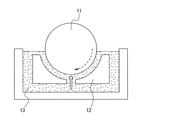
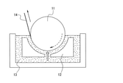
- the electrolytic copper foil can be manufactured, for example, by using an electrolytic precipitation device as shown in FIGS. 1 and 2.
- the electrolytic precipitation apparatus of FIGS. 1 and 2 includes an insoluble electrode 12 made of titanium coated with a platinum group element or an oxide thereof, and a titanium rotating electrode 11 provided facing the insoluble electrode 12. There is.
- Copper plating is performed using an electrolytic precipitation device, copper is deposited on the surface (columnar surface) of the columnar rotating electrode 11 to form a copper foil, and the copper foil is peeled off from the surface of the rotating electrode 11.
- the electrolytic copper foil of the present embodiment can be produced, the surface of the rotating electrode 11 is oxidized (hereinafter, may be referred to as “anode oxidation”) before copper plating, so that the surface of the rotating electrode 11 is more than a natural oxide film.
- An oxide film having a thick and uniform thickness may be formed.
- a natural oxide film having a thickness of about several nm is formed on the surface of the rotating electrode 11, but the surface on which the natural oxide film is formed is further anodic oxidized to form an anodic oxide film. If an oxide film composed of a natural oxide film and an anode oxide film is formed, an oxide film thicker and more uniform than the natural oxide film is formed. If there is a distribution in the thickness of the oxide film, the resistance at the time of copper plating increases in the thick portion, and the plating amount decreases. As a result, the thickness of the electrolytic copper foil may be distributed, or pinholes may be generated in the electrolytic copper foil.
- an oxide film thicker than the natural oxide film and having a uniform thickness is formed by anodic oxidation, the distribution of foil thickness and pinholes can be suppressed. Further, due to the presence of the oxide film thicker than the natural oxide film, copper plating is performed at a higher overvoltage, so that the crystal grains of the initial precipitation layer of plating become fine. As a result, the elongation of the electrolytic copper foil after softening at room temperature is improved, the glossiness of the electrolytic precipitation end surface is improved, and the surface roughness is reduced. Therefore, it is possible to manufacture an electrolytic copper foil that is unlikely to break during expansion and contraction when used as a negative electrode current collector.
- the thickness of the anodic oxide film formed by anodic oxidation is controlled by the amount of electricity applied to the rotating electrode 11 (unit is C / dm 2 ), and more specifically, the amount of electricity per unit area of the surface of the rotating electrode 11. be able to.
- the thickness of the anodic oxide film it is possible to control the thickness of the oxide film composed of the natural oxide film and the anodic oxide film.
- the amount of electricity applied to the rotating electrode 11 is preferably 1000 C / dm 2 or more and 5000 C / dm 2 or less.
- anodic oxidation will be described with reference to FIG.
- a current is applied using the rotating electrode 11 as the anode and the insoluble electrode 12 as the cathode.
- the insoluble electrode 12 for example, a DSE (Dimensionally Stable Electrode) electrode (registered trademark) can be used.
- the electrolytic solution 13 for example, a phosphoric acid aqueous solution having a concentration of 20% can be used.
- the electrolytic solution 13 for example, an aqueous solution containing sulfuric acid and copper sulfate can be used as the electrolytic solution 13 for example.
- the copper concentration of the electrolytic solution 13 can be, for example, 50 to 150 g / L, and the sulfuric acid concentration can be, for example, 20 to 200 g / L.
- Additives such as organic additives and inorganic additives may be added to the electrolytic solution 13 used for copper plating from the viewpoint of smoothing the electrolytic copper foil and controlling mechanical properties. By adding the additive, the strength, elongation, surface roughness, and glossiness under normal conditions can be improved.
- One type of additive may be used alone, or two or more types may be used in combination.
- organic additive examples include ethylenethiourea, polyethylene glycol, and Janus Green.
- metal chloride such as sodium chloride (NaCl) or hydrogen chloride (HCl) can be used as a source of chloride ions.
- the electrolysis conditions for copper plating can be, for example, as follows. That is, the liquid temperature of the electrolytic solution 13 is 18 to 67 ° C., and the current density is 3 to 67 A / dm 2 .
- the surface of the electrolytic copper foil produced as described above may be surface-treated.
- the surface treatment will be described below.
- the surface of the electrolytic copper foil may be subjected to a rust preventive treatment.
- the rust preventive treatment include an inorganic rust preventive treatment and an organic rust preventive treatment.
- the inorganic rust preventive treatment include chromate treatment and plating treatment, and chromate treatment may be applied to the plating layer by the plating treatment.
- the plating treatment include nickel plating, nickel alloy plating, cobalt plating, cobalt alloy plating, zinc plating, zinc alloy plating, tin plating, and tin alloy plating.
- the organic rust preventive treatment include surface treatment using benzotriazole.
- the surface that has been subjected to the rust preventive treatment may be further subjected to surface treatment (silane treatment) using a silane coupling agent.
- silane treatment silane treatment
- a functional group having a strong affinity with an adhesive is imparted to the surface of the electrolytic copper foil (the surface on the bonding side with the negative electrode material or the resin), so that the electrolytic copper foil and the negative electrode material are provided. Adhesion with the resin and the resin is further improved, and the rust resistance and moisture absorption heat resistance of the electrolytic copper foil are further improved. Therefore, such an electrolytic copper foil is suitable as an electrolytic copper foil for a negative electrode current collector of a lithium ion secondary battery.
- the rust preventive treatment and the silane coupling agent treatment increase the adhesion strength between the active material of the lithium ion secondary battery and the electrolytic copper foil, and play a role of preventing deterioration of the charge / discharge cycle characteristics of the lithium ion secondary battery.
- the surface of the electrolytic copper foil may be roughened before the above-mentioned rust preventive treatment is applied.
- a plating method, an etching method, or the like can be preferably adopted.
- the plating method is a method of roughening the surface by forming a thin film layer having irregularities on the surface of the untreated electrolytic copper foil. Examples of the plating method include an electrolytic plating method and an electroless plating method.
- the roughening treatment by the plating method for example, a method of forming a plating film containing copper as a main component such as copper or a copper alloy on the surface of an untreated electrolytic copper foil is preferable.
- a method by physical etching or chemical etching is preferable. Examples of the physical etching include a method of etching by sandblasting and the like, and examples of the chemical etching include etching performed by using a treatment liquid containing an inorganic acid or an organic acid, an oxidizing agent and an additive.
- Example ⁇ Hereinafter, the present invention will be described in more detail with reference to Examples and Comparative Examples.
- the electrolytic copper foils of Examples 1 to 27 and Comparative Examples 1 to 13 are manufactured, negative electrode current collectors are manufactured using these electrolytic copper foils, and a lithium ion secondary battery is manufactured using these negative electrode current collectors.
- a lithium ion secondary battery was manufactured using these negative electrode current collectors.
- various characteristics of the electrolytic copper foil and the lithium ion secondary battery were evaluated.
- a method for manufacturing an electrolytic copper foil and a lithium ion secondary battery and a method for evaluating various characteristics will be described.
- An aqueous solution containing sulfuric acid, copper sulfate pentahydrate, and additives was used as the electrolytic solution.
- additives ethylene thiourea, polyethylene glycol, and Janus Green were used.
- Table 1 shows the concentrations of sulfuric acid, copper sulfate pentahydrate, and each additive.
- the concentration of copper sulfate pentahydrate is the concentration as copper.
- Table 1 shows the chlorine concentration in the electrolytic solution.
- the surface of each electrolytic copper foil produced in the above item (B) was subjected to chromate treatment to form a rust preventive treatment layer, which was used as a negative electrode current collector.
- the conditions for chromate treatment are as follows.
- the plating solution used for the chromate treatment contains potassium dichromate, the chromium concentration is preferably in the range of 6 to 12 g / L, and the treatment time of the chromate treatment is in the range of 8 to 12 seconds. Is desirable.
- the chromium concentration was 10 g / L, and the chromate treatment treatment time was 10 seconds.
- Each negative electrode current collector manufactured in the above item (C) was cut into a strip having a width of 720 mm. At this time, the width direction of the electrolytic copper foil was made to coincide with the width direction of the strip obtained by cutting. Next, the negative electrode material paste was applied to both sides of the strip in a double stripe shape. The width of the coating film of the linear negative electrode material paste was 300 mm, and the direction in which the coating film of the linear negative electrode material paste was stretched was made parallel to the longitudinal direction of the strip.
- the strip coated with the negative electrode material paste was dried in a nitrogen atmosphere to volatilize the solvent, and then roll-rolled to prepare a sheet having an overall thickness of 150 ⁇ m. After cutting this sheet into a rectangular shape having a width of 43 mm and a length of 280 mm, a nickel foil lead terminal was attached to one end thereof by ultrasonic welding to form a negative electrode.
- the top lid made of insulating material was placed on the battery can, and after inserting the gasket, the lead terminal of the positive electrode and the safety valve made of aluminum were ultrasonically welded and connected. Then, after injecting a non-aqueous electrolyte solution consisting of propylene carbonate, diethyl carbonate, and ethylene carbonate into the battery can, a lid is attached to the safety valve, and a cylindrical sealed structure lithium ion battery with an outer diameter of 14 mm and a height of 50 mm is attached. I assembled the next battery.
- each electrolytic copper foil manufactured in the above item (B) and each lithium ion secondary battery manufactured in the above item (F) were evaluated.
- the evaluation method will be described below.
- the foil thickness of each electrolytic copper foil produced in the above item (B) is as shown in Table 2.
- the shape analysis was performed by the VSI measurement method (vertical scanning interferometry) using a high resolution CCD camera.
- the conditions were that the light source was white light, the resolution was 1280 ⁇ 980 pixels, the measurement magnification was 10 times, the measurement range was 477 ⁇ m ⁇ 357.8 ⁇ m, and Threshold was 3%. Further, the entire measurement range of 477 ⁇ m ⁇ 357.8 ⁇ m was filtered by Terms Removal (Cylinder and Tilt) and Data Ristorante (Measode: legacy, iterations 5), and then Fourier Filter processing was performed.
- the foil thickness t of the electrolytic copper foil is 10 or more and 20 or less, and Gs / t is high. Since it is 10 or more and 40 or less and the E / t is 0.9 or more and 1.8 or less, the electrolytic copper foil is less likely to break even after repeated charging and discharging, and the charge and discharge cycle characteristics of the lithium ion secondary battery are excellent. Was there.
Landscapes
- Chemical & Material Sciences (AREA)
- Chemical Kinetics & Catalysis (AREA)
- Electrochemistry (AREA)
- Engineering & Computer Science (AREA)
- Materials Engineering (AREA)
- General Chemical & Material Sciences (AREA)
- Metallurgy (AREA)
- Organic Chemistry (AREA)
- Cell Electrode Carriers And Collectors (AREA)
- Secondary Cells (AREA)
Abstract
Description
特許文献1、2には、リチウムイオン二次電池の負極集電体として使用可能な電解銅箔が開示されている。しかしながら、特許文献1、2に開示の電解銅箔は、機械的特性や負極材との密着性が不十分である場合があるため、リチウムイオン二次電池の充放電時に破断するおそれがあった。
さらに、本発明の他の態様に係るリチウムイオン二次電池は、上記他の態様に係るリチウムイオン二次電池用負極を備えることを要旨とする。
本発明の一実施形態に係る電解銅箔は、箔厚をt(単位はμm)、電解析出終了面に対して長さ方向に沿って入射角60°で光を照射して測定した電解析出終了面の光沢度をGs(単位は%)、長さ方向に沿って引っ張って測定した伸びをE(単位は%)としたとき、箔厚tが10以上20以下であり、光沢度Gsを箔厚tで除したGs/tが10以上40以下であり、伸びEを箔厚tで除したE/tが0.9以上1.8以下である。
このような構成から、本実施形態の電解銅箔は、破断が生じにくい。
本実施形態の電解銅箔が破断しにくいので、本実施形態のリチウムイオン二次電池用負極及びリチウムイオン二次電池は、充放電時に負極集電体に破断が生じにくい。
本発明者は、鋭意検討の結果、高延伸性と電解析出終了面の高光沢性との両方を備える電解銅箔が、リチウムイオン二次電池の充放電時に負極材が膨張収縮しても破断が生じにくいことを見出した。
電解銅箔は、室温程度の温度で結晶粒の再結晶が進行する、常温軟化現象が起きることが知られているが、析出直後に結晶粒が微細なほど再結晶の駆動力が大きくなり、常温軟化後に粒成長が停止した後の結晶粒がより大きくなると考えられる。したがって、後述する酸化膜の厚さの制御によってより微細な結晶粒を析出させれば、常温軟化後の電解銅箔の内部の結晶粒が大きくなって、伸びが向上すると考えられる。
また、伸びについても箔厚と結晶粒の2つの寄与が考えられ、製箔直後の結晶粒微細化の伸びへの寄与を類推する際には、伸びEを箔厚tで規格化したE/tを規定する必要があると考えられる。
これら光沢度Gsを箔厚tで規格化したパラメータGs/tと、伸びEを箔厚tで規格化したパラメータE/tの両方を規定することにより、破断が生じにくい電解銅箔が得られることが分かった。
パラメータGs/tは、10以上40以下である必要があるが、25以上40以下であることが好ましい。パラメータGs/tが上記範囲内であれば、電解銅箔の表面が平坦であるため、電解銅箔と負極材との密着力が密着面全体にわたって均一となりやすい。そのため、密着している電解銅箔と負極材との間に充放電時に局所的な剥離が生じることが抑制されるので、充放電時に破断が生じにくい。一方、パラメータGs/tが上記範囲内であれば、電解銅箔と負極材との密着力は十分発現するので、充放電時に破断が生じにくい。
パラメータE/tは、0.9以上1.8以下である必要があるが、1.2以上1.7以下であることが好ましく、1.3以上1.6以下であることがより好ましい。パラメータE/tが上記範囲内であれば、電解銅箔が高延伸性であるため、充放電時に破断が生じにくい。
本実施形態の電解銅箔の電解析出終了面の、白色干渉顕微鏡を用いて測定した二乗平均平方根高さSqは、0.1μm以上0.4μm以下であることが好ましく、0.1μm以上0.25μm以下であることがより好ましい。
本実施形態の電解銅箔は、長さ方向に沿って引っ張って測定した引張強度が300MPa以上380MPa以下であることが好ましい。引張強度が上記範囲内であれば、電解銅箔がより破断しにくいことに加えて、負極材の膨張収縮に対する追従性がより優れている。電解銅箔の「長さ方向」の定義は、光沢度Gsの場合と同様である。
本実施形態の電解銅箔の製造方法の一例について以下に説明する。
電解銅箔は、例えば、図1、2に示すような電解析出装置を用いて製造することができる。図1、2の電解析出装置は、白金族元素又はその酸化物を被覆したチタンからなる不溶性電極12と、不溶性電極12に対向して設けられたチタン製の回転電極11と、を備えている。
無機添加剤としては、例えば、塩化物イオンの供給源として塩化ナトリウム(NaCl)等の金属塩化物や塩化水素(HCl)を用いることができる。
銅メッキにおける電解条件は、例えば、下記の通りとすることができる。すなわち、電解液13の液温は18~67℃、電流密度は3~67A/dm2である。
電解銅箔の表面には防錆処理を施してもよい。防錆処理としては、無機防錆処理と有機防錆処理が挙げられる。無機防錆処理としては、例えば、クロメート処理、メッキ処理が挙げられ、該メッキ処理によるメッキ層上にクロメート処理を施してもよい。メッキ処理としては、例えば、ニッケルメッキ、ニッケル合金メッキ、コバルトメッキ、コバルト合金メッキ、亜鉛メッキ、亜鉛合金メッキ、錫メッキ、錫合金メッキが挙げられる。有機防錆処理としては、例えば、ベンゾトリアゾールを用いた表面処理が挙げられる。
防錆処理やシランカップリング剤処理は、リチウムイオン二次電池の活物質と電解銅箔との密着強度を高め、リチウムイオン二次電池の充放電サイクル特性の低下を防ぐ役割を果たす。
以下に実施例及び比較例を示して、本発明をさらに具体的に説明する。実施例1~27及び比較例1~13の電解銅箔を製造し、これらの電解銅箔を用いて負極集電体をそれぞれ製造し、これらの負極集電体を用いてリチウムイオン二次電池をそれぞれ製造した。そして、電解銅箔及びリチウムイオン二次電池の種々の特性を評価した。電解銅箔及びリチウムイオン二次電池の製造方法と各種特性の評価方法について説明する。
図1と同様の装置を用い前述と同様の操作でアノード酸化を行い、回転電極の表面に酸化膜を形成した。電解液には濃度20%のリン酸水溶液を用いた。酸化膜の厚さは、回転電極に印加する電気量によって制御した。回転電極に印加した電気量を、表1に示す。比較例8~10は、アノード酸化を行わなかった例である。

上記(A)項のアノード酸化に続けて前述と同様の操作で銅メッキを行い、酸化膜が形成された回転電極の表面に銅を析出させた。そして、析出した銅を回転電極の表面から引き剥がし、連続的に巻き取ることにより、実施例及び比較例の電解銅箔を製造した(図2を参照)。銅メッキ時の電解液の温度及び電流密度は、表1に示すとおりである。
上記(B)項で製造した各電解銅箔の表面にそれぞれクロメート処理を施して防錆処理層を形成し、負極集電体とした。クロメート処理の条件は以下の通りである。クロメート処理に用いたメッキ液は重クロム酸カリウムを含有しており、クロム濃度は6~12g/Lの範囲内であることが望ましく、クロメート処理の処理時間は8~12秒の範囲内であることが望ましい。本実施例及び比較例においては、クロム濃度は10g/L、クロメート処理の処理時間は10秒とした。
コバルト酸リチウム(LiCoO2)粉末90質量%、黒鉛粉末7質量%、ポリフッ化ビニリデン粉末3質量%を混合したものに、溶剤としてN-メチル-2-ピロリドンとエタノールを添加し混練して、正極材ペーストを調製した。この正極材ペーストをアルミニウム箔の上に厚さ15μmで均一に塗着した。正極材ペーストを塗着したアルミニウム箔を窒素雰囲気中で乾燥して溶剤を揮散させた後に、ロール圧延を行って、全体の厚さが150μmであるシートを作製した。このシートを幅43mm、長さ285mmの帯状に切断した後に、その一端にアルミ箔のリード端子を超音波溶接で取り付け、正極とした。
平均粒径10μmの天然黒鉛粉末90質量%とポリフッ化ビニリデン粉末10質量%を混合したものに、溶剤としてN-メチル-2-ピロリドンとエタノールを添加し混練して、負極材ペーストを調製した。
上記のように製造した正極と負極の間に、厚さ25μmのポリプロピレン製のセパレータを挟み、これら全体を巻いて捲回体を得た。この捲回体を円筒形の電池缶に収容して、負極のリード端子を電池缶の底部にスポット溶接した。なお、電池缶は、表面にニッケルメッキを施した軟鋼で形成されている。
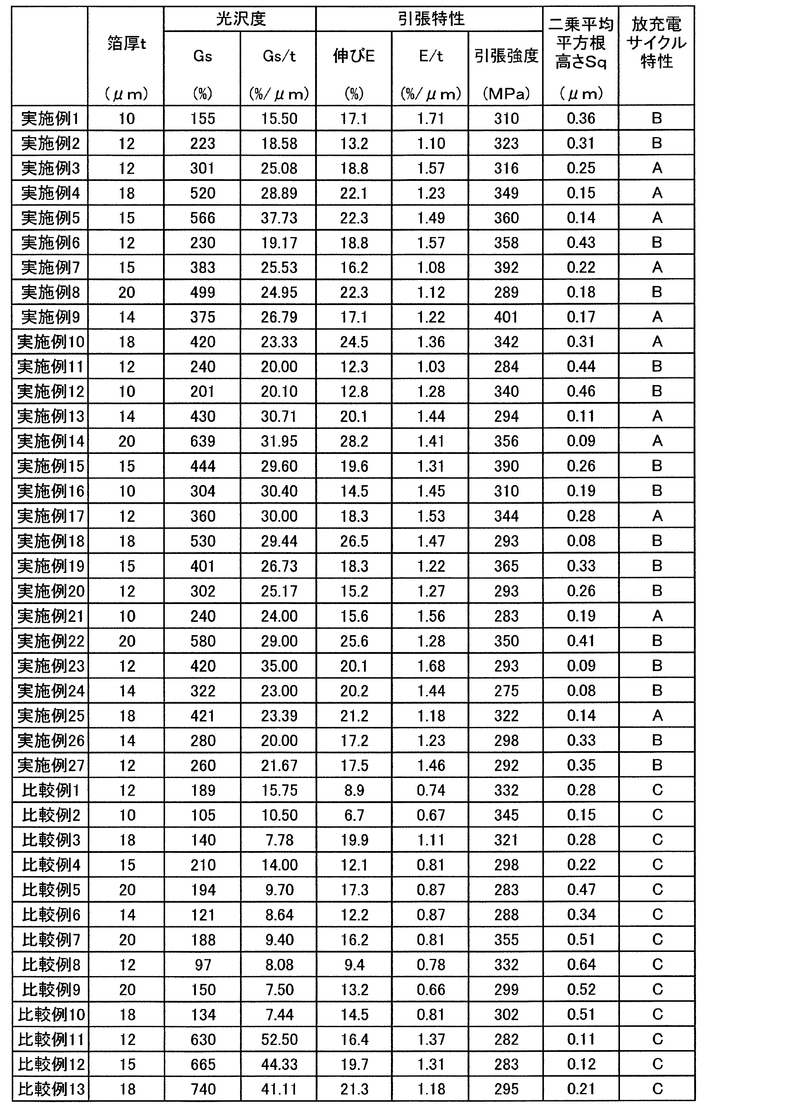
日本電色工業株式会社製の光沢度計VG7000を使用し、JIS Z8741-1997に規定された方法に基づいて、電解銅箔の電解析出終了面の光沢度を測定した。この光沢度の測定においては、電解銅箔の長さ方向(MD)に沿って入射角60°で電解析出終了面に光を照射して光沢度を測定した。光沢度の測定は5回行い、これらの平均値を光沢度Gsとした。結果を表2に示す。
なお、上記の光沢度の測定は、常態の電解銅箔を測定対象として行った。本発明において「常態」とは、電解銅箔が常温常湿(例えば温度23±2℃、湿度50±5%RH)におかれた状態のことを意味する。
熱処理を施していない常態の電解銅箔を、幅12.7mm、長さ130mmの長方形状に切断して、これを測定用サンプルとした。そして、インストロン社製の引張試験機1122型を使用し、IPC-TM-650に規定された方法に基づいて、測定用サンプルの引張試験を行い、破断伸びと引張強度を測定した。この引張試験においては、チャック間距離を70mm、引張速度を50mm/minとした。5つの測定用サンプルについて引張試験を行い、これらの平均値を伸びE及び引張強度とした。結果を表2に示す。
ISO25178を参考に、常態の電解銅箔を測定対象として、BRUKER社製の白色光干渉型光学顕微鏡Wyko ContourGT-Kを用いて、電解銅箔の電解析出終了面の表面形状を測定し、形状解析を行って、二乗平均平方根高さSqを求めた。表面形状の測定は、電解析出終了面の任意の5箇所で行い、5箇所それぞれ形状解析を行って、5箇所それぞれ二乗平均平方根高さSqを求めた。そして、得られた5箇所の結果の平均値を電解銅箔の電解析出終了面の二乗平均平方根高さSqとした。
さらに、Statistic Filter(Filter Size:3、Filter Type:Median)処理を行った。
二乗平均平方根高さSqは、S parameters-height解析でRemove TiltをTrueとして算出した。結果を表2に示す。
リチウムイオン二次電池に対して、充電電流100mAで4.2Vになるまで充電した後に、放電電流100mAで2.4Vになるまで放電するサイクルを1サイクルとする充放電サイクル試験を行った。このサイクルを繰り返した後に、リチウムイオン二次電池を分解し電解銅箔の破断の有無を調べた。結果を表2に示す。
300サイクル未満で破断する電解銅箔は、負極集電体の用途には適さないと言える。300サイクル以上500サイクル未満で破断する電解銅箔は、負極集電体の用途に適していると言える。500サイクル以上でも破断しない電解銅箔は、負極集電体の用途に特に適しており、リチウムイオン二次電池の充放電サイクル特性を良好とすることができる。
12・・・不溶性電極
13・・・電解液
14・・・電解銅箔
Claims (9)
- 箔厚をt(単位はμm)、電解析出終了面に対して長さ方向に沿って入射角60°で光を照射して測定した前記電解析出終了面の光沢度をGs(単位は%)、長さ方向に沿って引っ張って測定した伸びをE(単位は%)としたとき、箔厚tが10以上20以下であり、光沢度Gsを箔厚tで除したGs/tが10以上40以下であり、伸びEを箔厚tで除したE/tが0.9以上1.8以下である電解銅箔。
- 箔厚tが12以上20以下であり、光沢度Gsを箔厚tで除したGs/tが25以上40以下であり、伸びEを箔厚tで除したE/tが1.2以上1.7以下である請求項1に記載の電解銅箔。
- 伸びEを箔厚tで除したE/tが1.3以上1.6以下である請求項1又は請求項2に記載の電解銅箔。
- 白色干渉顕微鏡を用いて測定した前記電解析出終了面の二乗平均平方根高さSqが0.1μm以上0.4μm以下である請求項1~3のいずれか一項に記載の電解銅箔。
- 白色干渉顕微鏡を用いて測定した前記電解析出終了面の二乗平均平方根高さSqが0.1μm以上0.25μm以下である請求項1~3のいずれか一項に記載の電解銅箔。
- 長さ方向に沿って引っ張って測定した引張強度が300MPa以上380MPa以下である請求項1~5のいずれか一項に記載の電解銅箔。
- リチウムイオン二次電池の負極集電体用である請求項1~6のいずれか一項に記載の電解銅箔。
- 請求項1~7のいずれか一項に記載の電解銅箔を備えるリチウムイオン二次電池用負極。
- 請求項8に記載のリチウムイオン二次電池用負極を備えるリチウムイオン二次電池。
Priority Applications (3)
| Application Number | Priority Date | Filing Date | Title |
|---|---|---|---|
| CN202180054656.XA CN116018429B (zh) | 2020-09-11 | 2021-08-26 | 电解铜箔、锂离子二次电池用负极以及锂离子二次电池 |
| JP2022515790A JP7741065B2 (ja) | 2020-09-11 | 2021-08-26 | 電解銅箔、リチウムイオン二次電池用負極、及びリチウムイオン二次電池 |
| KR1020237011533A KR20230066034A (ko) | 2020-09-11 | 2021-08-26 | 전해 동박, 리튬 이온 2차 전지용 부극 및, 리튬 이온 2차 전지 |
Applications Claiming Priority (2)
| Application Number | Priority Date | Filing Date | Title |
|---|---|---|---|
| JP2020-153301 | 2020-09-11 | ||
| JP2020153301 | 2020-09-11 |
Publications (1)
| Publication Number | Publication Date |
|---|---|
| WO2022054597A1 true WO2022054597A1 (ja) | 2022-03-17 |
Family
ID=80632377
Family Applications (1)
| Application Number | Title | Priority Date | Filing Date |
|---|---|---|---|
| PCT/JP2021/031362 Ceased WO2022054597A1 (ja) | 2020-09-11 | 2021-08-26 | 電解銅箔、リチウムイオン二次電池用負極、及びリチウムイオン二次電池 |
Country Status (5)
| Country | Link |
|---|---|
| JP (1) | JP7741065B2 (ja) |
| KR (1) | KR20230066034A (ja) |
| CN (1) | CN116018429B (ja) |
| TW (1) | TWI915414B (ja) |
| WO (1) | WO2022054597A1 (ja) |
Cited By (2)
| Publication number | Priority date | Publication date | Assignee | Title |
|---|---|---|---|---|
| EP4299795A1 (en) * | 2022-06-28 | 2024-01-03 | Chang Chun Petrochemical Co., Ltd. | Electrolytic copper foil and electrode and lithium-ion cell comprising the same |
| US12211990B2 (en) | 2022-06-28 | 2025-01-28 | Chang Chun Petrochemical Co., Ltd. | Electrolytic copper foil and electrode and lithium-ion cell comprising the same |
Citations (6)
| Publication number | Priority date | Publication date | Assignee | Title |
|---|---|---|---|---|
| JPH07216586A (ja) * | 1993-06-02 | 1995-08-15 | Furukawa Electric Co Ltd:The | カソード体表面への陽極酸化皮膜形成装置 |
| JPH07228996A (ja) * | 1993-12-24 | 1995-08-29 | Furukawa Electric Co Ltd:The | 金属箔の製造方法 |
| JPH08236120A (ja) * | 1995-03-01 | 1996-09-13 | Furukawa Electric Co Ltd:The | 多孔質電解金属箔の製造方法、その電解金属箔を用いた二次電池用電極 |
| WO2000015875A1 (fr) * | 1998-09-14 | 2000-03-23 | Mitsui Mining & Smelting Co., Ltd. | Feuille de cuivre poreuse, son utilisation et son procede de production |
| JP2008101267A (ja) * | 2006-04-28 | 2008-05-01 | Mitsui Mining & Smelting Co Ltd | 電解銅箔、その電解銅箔を用いた表面処理銅箔及びその表面処理銅箔を用いた銅張積層板並びにその電解銅箔の製造方法 |
| JP2009221592A (ja) * | 2007-10-31 | 2009-10-01 | Mitsui Mining & Smelting Co Ltd | 電解銅箔及びその電解銅箔の製造方法 |
Family Cites Families (5)
| Publication number | Priority date | Publication date | Assignee | Title |
|---|---|---|---|---|
| US5133205A (en) | 1990-11-13 | 1992-07-28 | Mannesmann Aktiengesellschaft | System and process for forming thin flat hot rolled steel strip |
| US5565847A (en) | 1994-11-23 | 1996-10-15 | International Business Machines Corporation | Magnetic tag using acoustic or magnetic interrogation |
| JP2017014608A (ja) | 2015-07-06 | 2017-01-19 | 古河電気工業株式会社 | 電解銅箔、リチウムイオン二次電池用負極電極及びリチウムイオン二次電池、プリント配線板並びに電磁波シールド材 |
| JP6748169B2 (ja) | 2018-09-25 | 2020-08-26 | 福田金属箔粉工業株式会社 | プリント配線板用電解銅箔及び該電解銅箔を用いた銅張積層板 |
| CN110629257A (zh) * | 2019-07-05 | 2019-12-31 | 九江德福科技股份有限公司 | 一种高抗拉锂电铜箔的制造方法 |
-
2021
- 2021-08-26 KR KR1020237011533A patent/KR20230066034A/ko active Pending
- 2021-08-26 JP JP2022515790A patent/JP7741065B2/ja active Active
- 2021-08-26 CN CN202180054656.XA patent/CN116018429B/zh active Active
- 2021-08-26 WO PCT/JP2021/031362 patent/WO2022054597A1/ja not_active Ceased
- 2021-09-09 TW TW110133534A patent/TWI915414B/zh active
Patent Citations (6)
| Publication number | Priority date | Publication date | Assignee | Title |
|---|---|---|---|---|
| JPH07216586A (ja) * | 1993-06-02 | 1995-08-15 | Furukawa Electric Co Ltd:The | カソード体表面への陽極酸化皮膜形成装置 |
| JPH07228996A (ja) * | 1993-12-24 | 1995-08-29 | Furukawa Electric Co Ltd:The | 金属箔の製造方法 |
| JPH08236120A (ja) * | 1995-03-01 | 1996-09-13 | Furukawa Electric Co Ltd:The | 多孔質電解金属箔の製造方法、その電解金属箔を用いた二次電池用電極 |
| WO2000015875A1 (fr) * | 1998-09-14 | 2000-03-23 | Mitsui Mining & Smelting Co., Ltd. | Feuille de cuivre poreuse, son utilisation et son procede de production |
| JP2008101267A (ja) * | 2006-04-28 | 2008-05-01 | Mitsui Mining & Smelting Co Ltd | 電解銅箔、その電解銅箔を用いた表面処理銅箔及びその表面処理銅箔を用いた銅張積層板並びにその電解銅箔の製造方法 |
| JP2009221592A (ja) * | 2007-10-31 | 2009-10-01 | Mitsui Mining & Smelting Co Ltd | 電解銅箔及びその電解銅箔の製造方法 |
Cited By (2)
| Publication number | Priority date | Publication date | Assignee | Title |
|---|---|---|---|---|
| EP4299795A1 (en) * | 2022-06-28 | 2024-01-03 | Chang Chun Petrochemical Co., Ltd. | Electrolytic copper foil and electrode and lithium-ion cell comprising the same |
| US12211990B2 (en) | 2022-06-28 | 2025-01-28 | Chang Chun Petrochemical Co., Ltd. | Electrolytic copper foil and electrode and lithium-ion cell comprising the same |
Also Published As
| Publication number | Publication date |
|---|---|
| JP7741065B2 (ja) | 2025-09-17 |
| TWI915414B (zh) | 2026-02-21 |
| CN116018429A (zh) | 2023-04-25 |
| TW202223162A (zh) | 2022-06-16 |
| CN116018429B (zh) | 2026-03-24 |
| JPWO2022054597A1 (ja) | 2022-03-17 |
| KR20230066034A (ko) | 2023-05-12 |
Similar Documents
| Publication | Publication Date | Title |
|---|---|---|
| TWI526578B (zh) | An electrolytic copper foil and a lithium ion secondary battery using the electrolytic copper foil as a current collector | |
| CN103911633B (zh) | 电解铜箔及其制法 | |
| EP3376574B1 (en) | Method for manufacturing an electrolytic copper foil, electrolytic copper foil obtainable by the method, electrode comprising the same, and secondary battery comprising the same | |
| JP7083029B2 (ja) | 高温寸法安全性及び集合組職安全性を有する電解銅箔及びその製造方法 | |
| JP6190980B2 (ja) | 電解銅箔、その電解銅箔を用いた各種製品 | |
| JP7008128B2 (ja) | 電解銅箔、その製造方法及びそれを含む高容量Li二次電池用陰極 | |
| JP6232302B2 (ja) | リチウムイオン電池用電極タブの製造方法 | |
| KR20180054985A (ko) | 말림이 최소화된 전해동박, 그것을 포함하는 전극, 그것을 포함하는 이차전지, 및 그것의 제조방법 | |
| WO2015186752A1 (ja) | 集電体用金属箔、集電体及び集電体用金属箔の製造方法 | |
| JP2020508399A (ja) | 優れた接着力を有する銅箔、それを備える電極、それを備える二次電池、及びその製造方法 | |
| JP7741065B2 (ja) | 電解銅箔、リチウムイオン二次電池用負極、及びリチウムイオン二次電池 | |
| TWI648415B (zh) | Electrolytic copper foil and lithium ion secondary battery using the same | |
| JP2022018781A (ja) | 硫化物全固体電池 | |
| WO2022085371A1 (ja) | 電解銅箔、リチウムイオン二次電池用負極、及びリチウムイオン二次電池 | |
| TW201404943A (zh) | 電解銅箔及其製造方法、鋰離子二次電池之負極電極以及鋰離子二次電池 | |
| KR102348461B1 (ko) | 표면처리 동박, 이의 제조방법 및 이를 포함한 이차전지용 음극 | |
| EP3608447B1 (en) | Copper foil with minimized bagginess, wrinkle and tear, electrode including the same, secondary battery including the same and method for manufacturing the same | |
| JP4460058B2 (ja) | リチウム2次電池電極用銅箔およびその製造方法、該銅箔を用いたリチウム2次電池用電極およびリチウム2次電池 | |
| CN115198319B (zh) | 电解铜箔及包含所述电解铜箔的电极与锂离子电池 | |
| JP2006202636A (ja) | リチウム2次電池電極用銅箔およびその製造方法、該銅箔を用いたリチウム2次電池用電極およびリチウム2次電池 | |
| JP2025146651A (ja) | リチウムイオン二次電池用の表面処理銅箔、集電体、及びリチウムイオン二次電池 | |
| JP2024004433A (ja) | 電解銅箔及び電極とそれを用いたリチウムイオン電池 | |
| CN110880601A (zh) | 具有最小化膨胀和撕裂的铜箔,包括其的电极,包括其的二次电池,及其制造方法 |
Legal Events
| Date | Code | Title | Description |
|---|---|---|---|
| ENP | Entry into the national phase |
Ref document number: 2022515790 Country of ref document: JP Kind code of ref document: A |
|
| 121 | Ep: the epo has been informed by wipo that ep was designated in this application |
Ref document number: 21866556 Country of ref document: EP Kind code of ref document: A1 |
|
| ENP | Entry into the national phase |
Ref document number: 20237011533 Country of ref document: KR Kind code of ref document: A |
|
| NENP | Non-entry into the national phase |
Ref country code: DE |
|
| 122 | Ep: pct application non-entry in european phase |
Ref document number: 21866556 Country of ref document: EP Kind code of ref document: A1 |