WO2022054141A1 - カテーテル、及び、再開通カテーテルシステム - Google Patents
カテーテル、及び、再開通カテーテルシステム Download PDFInfo
- Publication number
- WO2022054141A1 WO2022054141A1 PCT/JP2020/033998 JP2020033998W WO2022054141A1 WO 2022054141 A1 WO2022054141 A1 WO 2022054141A1 JP 2020033998 W JP2020033998 W JP 2020033998W WO 2022054141 A1 WO2022054141 A1 WO 2022054141A1
- Authority
- WO
- WIPO (PCT)
- Prior art keywords
- marker
- catheter
- shaft
- lumen
- tip
- Prior art date
- Legal status (The legal status is an assumption and is not a legal conclusion. Google has not performed a legal analysis and makes no representation as to the accuracy of the status listed.)
- Ceased
Links
Images






Classifications
-
- A—HUMAN NECESSITIES
- A61—MEDICAL OR VETERINARY SCIENCE; HYGIENE
- A61M—DEVICES FOR INTRODUCING MEDIA INTO, OR ONTO, THE BODY; DEVICES FOR TRANSDUCING BODY MEDIA OR FOR TAKING MEDIA FROM THE BODY; DEVICES FOR PRODUCING OR ENDING SLEEP OR STUPOR
- A61M25/00—Catheters; Hollow probes
- A61M25/01—Introducing, guiding, advancing, emplacing or holding catheters
Definitions
- the present invention relates to a catheter and a recanalization catheter system.
- Patent Documents 1 to 4 disclose a subendometrial approach that reinserts a medical device from a false lumen to a true lumen for CTO opening (recommunication).
- the false cavity refers to all dissected cavities other than the true cavities formed by the medical device.
- Patent Document 1 the medical device (occlusion-transverse device) is projected from the circumferential end of the catheter, and the medical device is reinserted into the true lumen.
- the medical device the medical device (guide wire) is projected from the side surface of the catheter, and the medical device is reinserted into the true cavity.
- the configurations of Patent Document 1 and Patent Document 2 have an advantage that re-entry from the false lumen to the true lumen is easy as compared with the configuration in which the medical device protrudes from the center in the circumferential direction of the catheter.
- Patent Document 1 and Patent Document 2 the protruding port of the medical device formed at the peripheral end (or the side surface of the catheter) of the catheter is oriented in the direction of the true cavity. Medical devices need to move forward.
- the techniques described in Patent Documents 1 to 4 have a problem that it is not easy to grasp the circumferential direction of the catheter in the blood vessel and the efficiency of the procedure is poor.
- such a problem is not limited to the opening of the CTO, but is common to all devices that require grasping the orientation in the circumferential direction in the blood vessel.
- such a problem is not limited to the vascular system, but is a general device inserted into the biological lumen, such as the lymphatic system, biliary system, urinary tract system, airway system, digestive system, secretory gland and reproductive organ. Common to.
- the present invention has been made to solve at least a part of the above-mentioned problems, and an object of the present invention is to provide a catheter capable of grasping a circumferential orientation in a living lumen.
- the present invention has been made to solve at least a part of the above-mentioned problems, and can be realized as the following forms.
- a catheter is provided.
- This catheter is a shaft having a first lumen extending in the longitudinal direction and a marker portion arranged on the side surface on the distal end side of the shaft, which has at least radiation impermeableness and an acoustic impedance different from that of the shaft.
- a marker portion having one of them is provided, and the marker portion extends substantially parallel to the first marker extending in the longitudinal direction of the shaft and substantially parallel to the longitudinal direction of the shaft, and the marker portion extends in the radial direction of the shaft.
- the first marker and the second marker include a second marker arranged at a position facing the first marker, and at least one of the position and the shape of the shaft in the longitudinal direction is different from each other.
- the catheter comprises a marker portion having at least one of radiation impermeable and acoustic impedance different from that of the shaft. If the marker portion is configured to have radiodensity opacity, the operator can visually recognize the marker portion of the catheter inserted into the living lumen on the X-ray image. On the other hand, if the marker portion has a configuration having an acoustic impedance different from that of the shaft, the operator can see on the image of IVUS (a sensor that acquires information on the living tissue by transmitting and receiving ultrasonic waves to the living tissue). , The marker part of the catheter inserted in the living lumen can be visually recognized.
- IVUS a sensor that acquires information on the living tissue by transmitting and receiving ultrasonic waves to the living tissue.
- the marker portion includes a first marker and a second marker in which at least one of the position and the shape in the longitudinal direction of the shaft is different from each other.
- the first and second markers in the longitudinal direction are changed, the operator can grasp the orientation of the catheter by the positional relationship between the shaft and the marker shown in the image.
- the shapes of the first and second markers are changed, the operator can grasp the direction of the catheter by the shape of the markers shown in the image.
- the first and second markers function as landmarks, so that it is possible to provide a catheter capable of grasping the orientation in the circumferential direction in the living lumen. As a result, it becomes possible to efficiently proceed with the procedure.
- the shaft is further arranged at a second lumen arranged side by side with the first lumen toward the distal end side from the proximal end portion of the shaft, and at the tip of the second lumen.
- the marker portion has an end surface having a tip opening communicating with the second lumen, and a protrusion including the first lumen and protruding toward the tip side from the end face, and the marker portion is the tip of the shaft.
- the side surfaces it may be arranged on the side surface of the protrusion and may not be arranged on the side facing the extension line of the central axis of the second lumen.
- the shaft further has a second lumen arranged side by side with the first lumen, for example, inserting the IVUS into the first lumen and penetrating the living tissue into the second lumen.
- Multiple medical devices can be held simultaneously within a single catheter, such as inserting a penetration guide wire for.
- the shaft is a projecting portion that protrudes toward the tip end side from the end surface on which the tip opening communicating with the second lumen is formed, and has a projecting portion including the first lumen. Therefore, a medical device (eg, delivery) inserted into the second lumen by inserting the IVUS into the first lumen and arranging an IVUS transducer (a site for transmitting and receiving ultrasonic waves to and receiving living tissue) in the protruding portion.
- the tip of the guide wire, the guide wire for penetration, etc. can be observed with IVUS.
- the surgeon can recognize the state in the living lumen (for example, CTO) and the position of the tip of the medical device in real time only by the image obtained by IVUS. That is, according to the catheter of this configuration, the skill of operating a plurality of devices separately, which is conventionally required for the procedure under the guidance of the sensor (for example, IVUS Guide), and the three-dimensional image of the sensor and the X-ray image are used.
- Sensor-guided procedures can be performed without the need for target reconstruction skills.
- the catheter of this configuration since the procedure can be realized only by referring to the image of the sensor, it is possible to reduce the frequency of acquiring the X-ray image, and the amount of exposure of the operator and the patient due to the X-ray imaging. It can be expected that the amount of contrast medium used for X-ray photography will be reduced. Further, according to the catheter of this configuration, since the marker portion is arranged on the side surface of the protruding portion among the side surfaces on the tip end side of the shaft, the operator can determine the position of the protruding portion where the IVUS transducer should be positioned. , Easy to grasp.
- the marker portion since the marker portion is not arranged on the side facing the extension line of the central axis of the second lumen, the marker portion blocks the field of view of the IVUS reflecting the medical device (in other words, from the transducer of the IVUS). Blocking ultrasonic waves transmitted and received toward medical devices) can be suppressed.
- the catheter of the above-described form further includes a connecting portion that is arranged on the side surface of the protruding portion, extends along the circumferential direction of the shaft, and connects the first marker and the second marker. May be good. According to this configuration, it is arranged on the side surface of the protrusion, extends along the circumferential direction of the shaft, and includes a connecting portion for connecting the first marker and the second marker. Therefore, the bending rigidity of the protruding portion can be improved, and the operability of the IVUS inserted into the first lumen can be improved.
- the connecting portion has an arc shape extending along the circumferential direction of the shaft, and the open portion between the start point and the end point of the arc is the central axis of the second lumen. It may be arranged on the side surface of the protruding portion in a state of facing the side facing the extension line of the above. According to this configuration, since the connecting portion has an arc shape extending along the circumferential direction of the shaft, the roundness of the protruding portion can be improved, and the operability of the IVUS inserted into the first lumen is improved. can.
- the connecting portion is arranged on the side surface of the protruding portion with the open portion between the start point and the end point of the arc facing the side facing the extension line of the central axis of the second lumen. Therefore, it is possible to prevent the connecting portion from blocking the field of view of the IVUS that reflects the medical device.
- the marker portion is a third marker arranged between the first marker and the second marker in the circumferential direction of the shaft, and is the second lumen.
- a third marker may be provided on the side opposite to the side facing the extension line of the central axis of the above.
- the marker portion is a third marker arranged between the first marker and the second marker in the circumferential direction of the shaft, and faces an extension of the central axis of the second lumen. It is provided with a third marker arranged on the side opposite to the side to be used. Therefore, in addition to the first and second markers, the third marker functions as a landmark, so that it is possible to provide a catheter in which the orientation in the circumferential direction can be more easily grasped in the living lumen.
- the range provided with the first marker and the range provided with the second marker may not overlap in the longitudinal direction of the shaft. According to this configuration, the range provided with the first marker and the range provided with the second marker do not overlap, so that the operator can easily select the first marker and the second marker. Can be identified. As a result, it is possible to provide a catheter that makes it easier to grasp the orientation in the circumferential direction in the lumen of the living body.
- At least one of the first marker and the second marker may be composed of a plurality of sub-markers arranged apart from each other in the longitudinal direction of the shaft.
- at least one of the first marker and the second marker is composed of a plurality of sub-markers arranged apart from each other in the longitudinal direction of the shaft, so that the first and second markers are arranged. The flexibility of the raised protrusion can be improved.
- a first intermediate portion located between the tip and the proximal end of the first marker is joined to the outer peripheral surface of the shaft, or the shaft of the shaft.
- the second marker is embedded in a thick portion, and a second intermediate portion located between the tip end and the base end of the second marker is joined to the outer peripheral surface of the shaft, or the shaft. It may be buried in a thick part. According to this configuration, the first and second intermediate portions of the first and second markers are respectively joined to the outer peripheral surface of the shaft or embedded in the thick portion of the shaft.
- the catheter advances through a biological tube having a small radius of curvature (in other words, a biological tube having a sharp curve)
- the first and second markers are in the radial direction of the shaft. It can suppress the swelling toward the outside (or reduce the swelling). As a result, the risk of dilating the false cavity during the procedure can be reduced.
- a recanalization catheter system is provided.
- This recanalization catheter system is inserted into the catheter of the above form, a sensor inserted into the first lumen to acquire information on living tissue in the first lumen, and inserted into the second lumen to the outside from the tip opening. It is provided with a guide wire that is guided and penetrates the living tissue.
- a catheter including a catheter, a method for manufacturing or using the catheter, a catheter and a sensor, a delivery guide wire, a penetration guide wire, and other devices. It can be realized in the form of a system, a method of manufacturing or using a catheter system, and the like.
- FIG. 3 is a cross-sectional view of the catheter taken along the line CC of FIG.
- It is a schematic diagram of an imaging sensor. It is a figure explaining the use method of the recanalization catheter system. It is a figure explaining the use method of the recanalization catheter system. It is a schematic bottom view of the distal end side of the catheter of the second embodiment. It is a schematic bottom view of the distal end side of the catheter of the third embodiment.
- FIG. 3 is a cross-sectional view of the catheter in line DD of FIG. It is a schematic bottom view of the distal end side of the catheter of the sixth embodiment. It is a schematic bottom view of the distal end side of the catheter of the seventh embodiment. It is a schematic bottom view of the distal end side of the catheter of the eighth embodiment. 9 is a cross-sectional view of the catheter of the ninth embodiment. It is a schematic side view of the distal end side of the catheter of the tenth embodiment.
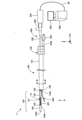
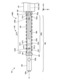
- FIG. 1 is an explanatory diagram illustrating the configuration of the recanalization catheter system 1.
- the recanalization catheter system 1 is used, for example, when treating a CTO (Chronic Total Occlusion) occurring in a blood vessel with an anterograde approach.
- the recanalization catheter system 1 includes a catheter 100, an imaging sensor 200, an imaging console 300, and a penetrating guide wire 400.
- a schematic side view of the catheter 100 is shown, and a part of the tip end side of the imaging sensor 200 inserted into the first inner shaft 102 is shown by a solid line.
- FIG. 1 includes a part in which the relative ratio of the sizes of each component is described so as to be different from the actual one for convenience of explanation. In addition, a part of each component is exaggerated and described. Further, FIG. 1 shows XYZ axes that are orthogonal to each other.
- the X-axis corresponds to the longitudinal direction of the catheter 100 and the penetrating guide wire 400
- the Y-axis corresponds to the height direction of the catheter 100 and the penetrating guide wire 400
- the Z-axis corresponds to the width of the catheter 100 and the penetrating guide wire 400. Corresponds to the direction.
- the tip side of the catheter 100 and each component is referred to as the "tip side” of the catheter 100 and each component
- the right side (+ X-axis direction) of FIG. 1 is referred to as the "base end side” of the catheter 100 and each component.
- one end located on the distal end side is referred to as "tip”
- the other end located on the proximal end side is referred to as "base end”.
- the tip and its vicinity are referred to as a "tip portion”
- the proximal end and its vicinity are referred to as a "base end portion”.
- the distal end side is inserted into the living body, and the proximal end side is operated by a surgeon such as a doctor.
- FIG. 2 is a schematic side view of the distal end side of the catheter 100.
- the lumen in the catheter 100 is represented by a broken line, and a part of the tip end side of the imaging sensor 200 inserted into the first inner shaft 102 is represented by a solid line.
- FIG. 3 is a schematic bottom view of the distal end side of the catheter 100.
- FIG. 3 is a view of the distal end side of the catheter 100 as viewed from the A direction (FIG. 1).
- FIG. 3 a part of the imaging sensor 200 inserted into the first inner shaft 102 on the distal end side is represented by a solid line.
- FIG. 4 is a cross-sectional view of the catheter 100 in line BB of FIG.
- FIG. 5 is a cross-sectional view of the catheter 100 in line CC of FIG. In FIG. 5, the imaging sensor 200 is not shown.
- the catheter 100 includes shafts 101 to 104, a marker portion 12, and a regulator 105.
- the catheter 100 includes shafts 101 to 104, a marker portion 12, and a regulator 105.
- diagonal hatching is attached to the marker portion 12 in order to distinguish it from other members.
- the shafts 101 to 104 include an outer shaft 101, a first inner shaft 102, a second inner shaft 103, a tip tip 104 (see FIG. 1), a sealing member 114, and a blade 115. And have.
- the outer shaft 101, the first inner shaft 102, and the second inner shaft 103 are all hollow and elongated, and have a substantially circular cross section.
- the first inner shaft 102 and the second inner shaft 103 are inserted into the lumen of the outer shaft 101, and extend substantially parallel to each other along the longitudinal direction of the outer shaft 101.
- a first lumen 102L is provided inside the first inner shaft 102.
- the first lumen 102L functions as a “sensor lumen” for inserting the imaging sensor 200 into the shafts 101 to 104.
- a second lumen 103L is provided inside the second inner shaft 103.
- the second lumen 103L functions as a "wire lumen" for inserting the delivery guide wire 70 (FIG. 2) and the penetrating guide wire 400 (FIG. 1) into the shafts 101 to 104. Details will be described later.
- the first lumen 102L and the second lumen 103L are arranged side by side so as to be substantially parallel to each other.
- the sealing member 114 seals (fixes) the first inner shaft 102 and the second inner shaft 103 in the outer shaft 101.
- the sealing member 114 is arranged inside the outer shaft 101 and outside the first inner shaft 102 and the second inner shaft 103.
- the outer shaft 101, the first inner shaft 102, the second inner shaft 103, and the sealing member 114 are formed of an insulating resin, and are, for example, polyolefins such as polyethylene, polypropylene, and an ethylene-propylene copolymer, and polyethylene tereph.
- polyester such as tarat, polyvinyl chloride, ethylene-vinyl acetate copolymer, crosslinked ethylene-vinyl acetate copolymer, thermoplastic resin such as polyurethane, polyamide elastomer, polyolefin elastomer, polyurethane elastomer, silicone rubber, latex rubber, etc.
- thermoplastic resin such as polyurethane, polyamide elastomer, polyolefin elastomer, polyurethane elastomer, silicone rubber, latex rubber, etc.
- the resin instead of the resin having an insulating property, it may be formed by a known material.
- the blade 115 is a reinforcing member formed by braiding a wire.
- the blade 115 is embedded in the thick portion of the outer shaft 101.
- the strands constituting the blade 115 can be formed of a metal material (for example, stainless steel such as SUS304, nickel-titanium alloy, alloy containing gold, platinum, and tungsten which are X-ray opaque materials).
- the strands constituting the blade 115 may be made of a known metal material other than these.
- a coil body formed by spirally winding a wire may be embedded in the thick portion of the outer shaft 101.
- the wire constituting the coil body can be formed of a known metal material like the blade 115.
- the length of the first inner shaft 102 is longer than the length of the outer shaft 101 and the second inner shaft 103.
- the length of the second inner shaft 103 is substantially the same as the length of the outer shaft 101, or slightly longer than the length of the outer shaft 101.
- the outer shaft 101, the first inner shaft 102, and the second inner shaft 103 are fixed with their base ends aligned. That is, as shown in FIG. 1, a part of the first inner shaft 102 on the tip end side and the end face 108 on the tip end side of the second inner shaft 103 each project from the tip end of the outer shaft 101.
- the imaging sensor 200 is arranged in a part on the tip end side of the first inner shaft 102 (a portion protruding from the tip end of the outer shaft 101).
- the state of the delivery guide wire 70 (FIG. 2) inserted through the second lumen 103L (wire lumen) and the penetrating guide wire 400 (FIG. 3) can be observed.
- the imaging sensor 200 transmits ultrasonic waves to a living tissue and receives the reflected sound from the transducer 201. Therefore, a part of the first inner shaft 102 on the tip end side (a portion protruding from the tip of the outer shaft 101) has a living tissue as compared with a portion of the first inner shaft 102 located inside the outer shaft 101.
- first inner shaft 102 on the tip end side is a portion of the first inner shaft 102 located inside the outer shaft 101 with the thickness of the thick portion. May be thinner than.
- the end surface 108 on the tip end side of the second inner shaft 103 is inclined outward from the side near the center of the outer shaft 101. Further, the end face 108 is formed with a tip opening 103a communicating with the second lumen 103L (lumen for wire).
- the tip tip 104 is joined to the tip of the first inner shaft 102.
- the tip tip 104 is a substantially columnar member having an R at the tip.
- the tip tip 104 may have any shape, and may be, for example, a substantially truncated cone whose outer diameter is reduced from the base end side toward the tip end side.
- the tip tip 104 is formed with a third lumen 104L extending in the longitudinal direction (X-axis direction) of the shafts 101 to 104. Further, a first opening 104a communicating with the third lumen 104L is formed on the tip surface of the tip tip 104. A second opening 104b communicating with the third lumen 104L is formed on the side surface of the tip tip 104. As shown in FIG.
- the first opening 104a is arranged closer to the tip side than the second opening 104b. Further, the second opening 104b is arranged on the tip side of the tip opening 103a of the second inner shaft 103.
- the tip 104 is preferably made of a flexible resin material, such as a polyurethane elastomer.
- a flexible resin material such as a polyurethane elastomer.
- bonding between the tip tip 104 and the first inner shaft 102 for example, bonding between resins by heat melting or bonding with an insulating adhesive such as an epoxy adhesive can be adopted.
- protruding portion 109 the portion of the tip end side of the first inner shaft 102 that protrudes toward the tip end side from the end surface 108 and the tip tip 104 are collectively referred to as a "protruding portion 109".
- the marker portion 12 is arranged on the side surface of the shafts 101 to 104 on the distal end side, specifically, on the side surface of the protruding portion 109, and functions as a mark indicating the position of the catheter 100 inserted into the blood vessel.
- the marker portion 12 has at least one of radiation opacity and acoustic impedance different from that of the shaft.
- the marker unit 12 has a first marker 121 and a second marker 122. Both the first and second markers 121 and 122 extend substantially parallel to the first inner shaft 102 along the longitudinal direction (X-axis direction) of the first inner shaft 102.
- the first and second markers 121 and 122 are flat plate-shaped members (or arc-shaped members along the outer peripheral surface of the first inner shaft 102) having a substantially rectangular shape.
- the first marker 121 and the second marker 122 are arranged at positions facing each other with the first inner shaft 102 interposed therebetween.
- the second marker 122 is arranged at a position facing the first marker 121 in the radial direction of the first inner shaft 102.
- both the first and second markers 121 and 122 face the extension line E of the central axis of the second lumen 103L (that is, the delivery guide wire 70 passes through in FIG. 2). It is not arranged on the side, the side through which the penetration guide wire 400 passes in FIG. 3).
- the first marker 121 and the second marker 122 are different in position in the longitudinal direction of the first inner shaft 102.
- the first marker 121 is arranged on the distal end side of the protruding portion 109
- the second marker 122 is arranged on the proximal end side of the protruding portion 109.
- the range in which the first marker 121 is provided and the range in which the second marker 122 is provided are different from each other and overlap. I haven't.
- the first intermediate portion 121a (broken line round frame) located between the tip end and the base end of the first marker 121 is joined to the outer peripheral surface of the first inner shaft 102.
- the second intermediate portion 122a (broken line round frame) located between the tip end and the base end of the second marker 122 is joined to the outer peripheral surface of the first inner shaft 102. .. Bonding can be achieved with any bonding agent such as an epoxy adhesive.
- the first intermediate portion 121a and the second intermediate portion 122a may be embedded in the thick portion of the first inner shaft 102 instead of being joined to the outer peripheral surface of the first inner shaft 102.
- first marker 121 and the entire second marker 122 are embedded in the thick portion of the first inner shaft 102 instead of being arranged on the outer peripheral surface of the first inner shaft 102. You may. Further, the first marker 121 and the second marker 122 made of a metal material may be directly formed on the outer peripheral surface of the first inner shaft 102 by electrolytic plating or the like. In this case, for example, a metal layer is formed on the outer peripheral surface of the first inner shaft 102 by electrolytic plating, and an etching resist made of a resin having etching resistance is applied on the outer peripheral surface of the metal layer.
- the etching resist is removed by irradiating the portions that do not form the first marker 121 and the second marker 122 with a laser from the outer periphery of the etching resist. After removing the etching resist, the exposed metal layer is melted with an etching solution. As a result, the first marker 121 and the second marker 122 can be formed by electrolytic plating.
- the tip end portion of the first marker 121 is fixed to the first inner shaft 102 by the tip fixing portion 128, and the base end portion of the first marker 121 is joined to the outer peripheral surface of the first inner shaft 102.
- the tip end portion of the second marker 122 is joined to the outer peripheral surface of the first inner shaft 102, and the proximal end portion of the second marker 122 is fixed to the first inner shaft 102 by the proximal end fixing portion 129.
- Both the tip fixing portion 128 and the base end fixing portion 129 are annular members arranged along the outer peripheral surface of the first inner shaft 102.
- the tip fixing portion 128 is joined to the tip portion of the protruding portion 109, and the proximal end fixing portion 129 is joined to the proximal end portion of the protruding portion 109. Bonding can be achieved with any bonding agent such as an epoxy adhesive. Further, the tip fixing portion 128 and the base end fixing portion 129 may be embedded in the side surface of the first inner shaft 102 by heat melting or the like. The tip fixing portion 128 and the base end fixing portion 129 may be omitted.
- the first and second markers 121 and 122 can be formed of a resin material or metal material having radiation opacity.
- a resin material when a resin material is used, it can be formed by mixing a radiation-impermeable material such as bismuth trioxide, tungsten, barium sulfate, etc. with a polyamide resin, a polyolefin resin, a polyester resin, a polyurethane resin, a silicon resin, a fluororesin, or the like.
- a metal material when a metal material is used, it can be formed of a radiation-impermeable material such as gold, platinum, tungsten, or an alloy containing these elements (for example, platinum-nickel alloy).
- the first and second markers 121 and 122 and a part of the first inner shaft 102 on the tip end side are provided. At least one of the material and the thickness of the thick portion may be different.
- the tip fixing portion 128 and the base end fixing portion 129 may be formed of the same material as the first marker 121, or may be formed of a well-known resin material different from the first marker 121.
- the controller 105 is an operation unit for moving forward and backward of the imaging sensor 200 in the first lumen 102L.
- the controller 105 includes a dial that can be operated by the operator, and by rotating the dial, the imaging sensor 200 inserted in the first lumen 102L moves forward or backward.
- the regulator 105 is made of an insulating resin or a known material. The material of the regulator 105 may be the same as or different from the material of the outer shaft 101.
- the "first case” in which the delivery guide wire 70 is inserted through the catheter 100 will be described with reference to FIG.
- the base end portion of the delivery guide wire 70 is inserted from the first opening 104a into the third lumen 104L, pulled out from the second opening 104b, and inserted again from the tip opening 103a into the second lumen 103L. Then, it is pulled out from the opening 103b on the base end side of the second lumen 103L.
- a side opening (not shown) that communicates the second lumen 103L with the outside may be provided on the base end side of the tip opening 103a.
- the base end portion of the delivery guide wire 70 can be pulled out from the side opening instead of the opening 103b on the base end side of the second lumen 103L, so that the delivery guide wire 70 can be pulled out.
- the time required for the insertion can be shortened.
- the "second case" in which the penetration guide wire 400 is inserted through the catheter 100 will be described with reference to FIGS. 1 and 3.
- the tip of the penetrating guide wire 400 is inserted through the opening 103b on the base end side of the second lumen 103L into the second lumen 103L and pulled out from the tip opening 103a to the outside.
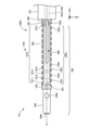
- FIG. 6 is a schematic diagram of the imaging sensor 200.
- the imaging sensor 200 is a "sensor" having a long outer shape and acquiring information on living tissue.
- the imaging sensor 200 has a transducer 201, a driving cable 202, a connector 203, and a motor drive 204.
- the transducer 201 is an ultrasonic probe (ultrasonic transducer, piezoelectric body, ultrasonic transmission / reception element, ultrasonic element) that emits ultrasonic waves toward a living tissue and receives ultrasonic waves propagated through the living tissue and reflected. Also called).
- the driving cable 202 has a coaxial line inside the driving cable 202 that electrically connects the transducer 201 and the motor drive 204.
- the connector 203 connects the coaxial line of the driving cable 202 and the motor drive 204 that controls the rotation of the transducer 201.
- the motor drive 204 is electrically connected to the imaging console 300 by a cable 50.
- the imaging console 300 shown in FIG. 1 controls the imaging sensor 200 and generates and displays an image. Specifically, the imaging console 300 moves the transducer 201 in the first lumen 102L in the longitudinal direction (X-axis direction) of the first inner shaft 102 in response to the operation of the controller 105, and the first The inner shaft 102 is rotated in the circumferential direction (YZ axis direction). Further, the imaging console 300 transmits ultrasonic waves from the transducer 201 and receives reflected waves by the transducer 201 in response to an operator's operation via an input means (not shown). The reflected wave received by the transducer 201 is transmitted to the imaging console 300 via the driving cable 202 and the cable 50.
- the imaging console 300 generates an image (two-dimensional image) with shades of gradation according to the intensity of the received reflected wave, and displays the generated image on the display 302.
- the image acquired by the imaging sensor 200 and displayed on the display 302 is also referred to as a “sensor image”.
- the penetrating guide wire 400 shown in FIG. 1 is a long medical device having a pointed portion at the tip.
- the pointed portion is a portion having a wedge shape or a wedge shape from the proximal end side to the distal end side.
- the living tissue can be penetrated by the pointed portion provided at the tip.
- the penetrating guide wire 400 corresponds to a "guide wire penetrating a living tissue".
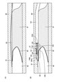
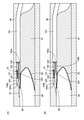
- FIGS. 7 and 8 are diagrams illustrating how to use the recanalization catheter system 1.
- the coronary artery 80 as an example of the biological lumen
- the CTO 81 generated in the coronary artery 80 and the pseudo-lumen 82 (formed by the delivery guide wire 70) formed in the endometrium or subintimal region of the coronary artery 80 are formed.
- All dissociation cavities other than the true lumen), and the fibrous membrane or plaque 83 hereinafter also referred to as “fibrous membrane 83” existing between the true lumen 84 and the false lumen 82 and the true lumen 84.
- the fibrous film 83 may be formed in a fibrous form on the surface of the CTO lesion.
- FIG. 7A shows a state in which the delivery guide wire 70 is inserted into the coronary artery 80.
- the operator-operated delivery guide wire 70 has entered the endometrium of the coronary artery 80 or has formed a pseudocavity 82 under the endometrium.
- FIG. 7B shows how the catheter 100 is delivered using the delivery guide wire 70.
- the operator inserts the proximal end of the delivery guide wire 70 from the first opening 104a of the catheter 100 into the third lumen 104L, exposes it to the outside through the second opening 104b, and inserts it from the tip opening 103a into the second lumen 103L. do.
- the surgeon then delivers the catheter 100 to the pseudocavity 82 along the delivery guide wire 70, as shown in FIG. 7B.
- FIG. 8A shows how the positions of the catheter 100 and the imaging sensor 200 are adjusted.
- the surgeon adjusts each position shown in the following a1 to a3.
- A1 Adjustment of the position of the catheter 100 in the longitudinal direction (FIG. 1: X-axis direction).
- the surgeon places the protrusion 109 of the catheter 100 in an optimal position for penetration into the true lumen 84 by the penetrating guide wire 400.
- Adjustment a1 can be performed while confirming the marker portion 12 on the X-ray image or the true cavity 84 on the sensor image.
- Adjustment of the orientation of the catheter 100 in the circumferential direction (FIG. 1: YZ axis direction).
- the operator By rotating the catheter 100 in the circumferential direction, the operator adjusts the catheter 100 so as to have the indicated orientation (that is, the orientation in which the tip opening 103a is located on the CTO81 side).
- Adjustment a2 can be performed while checking the marker unit 12 on the X-ray image or the marker unit 12 on the sensor image.
- the position of the marker portion 12 is different between the first marker 121 and the second marker 122 in the longitudinal direction (FIG. 3). Therefore, the operator can grasp the orientation of the catheter 100 by the positional relationship between the first inner shaft 102 and the marker portion 12 (first marker 121, second marker 122) shown in the image.
- the adjustment a2 may be performed while confirming the positional relationship between the delivery guide wire 70 and the coronary artery 80 on the sensor image.
- the operator moves the transducer 201 so that the transducer 201 is in a suitable position for observing the penetration of the penetrating guide wire 400.
- Adjustment a3 can be performed while checking the marker portion 12 on the sensor image and the coronary artery 80 on the sensor image.
- FIG. 8B shows how the penetrating guide wire 400 penetrates the living tissue.
- the operator removes the delivery guide wire 70 and inserts the penetrating guide wire 400 into the second lumen 103L through the opening 103b (FIG. 1) on the proximal end side of the catheter 100. After that, the operator projects the tip of the penetrating guide wire 400 from the tip opening 103a. While confirming the tip of the penetrating guide wire 400 on the sensor image, the operator guides the pointed portion of the penetrating guide wire 400 to the above-mentioned optimum site for penetration. Then, the pointed portion of the penetrating guide wire 400 is used to penetrate the living tissue, and the tip of the penetrating guide wire 400 is made to reach the true cavity 84.
- the CTO81 can be opened by the reopening catheter system 1.
- the method described above is merely an example, and the recanalization catheter system 1 can be used in various procedures.
- the recanalization catheter system 1 is used not only for the approach from the false lumen 82 to the true lumen 84 but also for the approach through the CTO from the proximal true lumen 84 to the distal true lumen 84. May be done.
- the catheter 100 of the first embodiment has a marker portion 12 (first) having at least one of radiation impermeableness and an acoustic impedance different from that of the shaft (a part of the tip end side of the first inner shaft 102). 1 and 2nd markers 121 and 122) are provided. If the marker portion 12 is configured to have radiation opacity, the operator can visually recognize the marker portion 12 of the catheter 100 inserted into the living lumen on the X-ray image. On the other hand, if the marker portion 12 has a configuration having an acoustic impedance different from that of the shaft, the operator can obtain the image sensor 200 (a sensor that acquires information on the living tissue by transmitting and receiving ultrasonic waves to the living tissue, ".
- the marker portion 12 of the catheter 100 inserted into the biological lumen can be visually recognized.
- the marker unit 12 includes a first marker 121 and a second marker 122 whose positions in the longitudinal direction of the first inner shaft 102 are different from each other.
- the operator can grasp the orientation of the catheter 100 by the positional relationship between the first inner shaft 102 and the marker portion 12 shown in the image.
- the first and second markers 121 and 122 function as landmarks to provide a catheter 100 capable of grasping the circumferential orientation in the living lumen. Can be provided. As a result, it becomes possible to efficiently proceed with the procedure.
- the shafts 101 to 104 further have a second lumen 103L arranged side by side with the first lumen 102L. Therefore, for example, the imaging sensor 200 (IVUS) is inserted into the first lumen 102L, and the penetrating guide wire 400 for penetrating the living tissue is inserted into the second lumen 103L. It can be held simultaneously in one catheter 100.
- the shafts 101 to 104 are protrusions 109 that protrude toward the tip side of the end surface 108 on which the tip opening 103a communicating with the second lumen 103L is formed, and have a protrusion 109 including the first lumen 102L. ing.
- the imaging sensor 200 is inserted into the second lumen 103L.
- the tip of the medical device for example, the delivery guide wire 70, the penetrating guide wire 400, etc.
- the imaging sensor 200 can recognize the state in the living lumen (for example, CTO81) and the position of the tip of the medical device in real time only by the image obtained by the imaging sensor 200.
- the skill of operating a plurality of devices separately which is conventionally required in the procedure under the guidance of the imaging sensor 200 (for example, IVUS Guide), and the sensor image and the X are used.
- the procedure under the guidance of the imaging sensor 200 can be realized without requiring the skill of three-dimensional reconstruction of the line image.
- the catheter 100 of the first embodiment since the procedure can be realized only by referring to the sensor image of the imaging sensor 200, the frequency of acquiring the X-ray image can be reduced, and the technique associated with the X-ray imaging can be performed. It is expected that the amount of exposure to people and patients will be reduced, and the amount of contrast medium used for X-ray photography will be reduced.
- the marker portion 12 is arranged on the side surface of the protruding portion 109 among the side surfaces on the distal end side of the shafts 101 to 104. Therefore, the operator can easily grasp the position of the protrusion 109 to which the transducer 201 of the imaging sensor 200 (IVUS) should be located. Further, the marker portion 12 is not arranged on the side of the second lumen 103L facing the extension line E of the central axis (FIG. 5). Therefore, the marker unit 12 blocks the field of view of the imaging sensor 200 that reflects the medical device such as the delivery guide wire 70 and the penetrating guide wire 400 (in other words, the transducer 201 of the imaging sensor 200 transmits to the medical device. And blocking the received ultrasonic waves) can be suppressed.
- the range provided with the first marker 121 and the range provided with the second marker 122 do not overlap (FIG. 3). Therefore, the operator can easily distinguish between the first marker 121 and the second marker 122. As a result, it is possible to provide the catheter 100 in which the orientation in the circumferential direction can be more easily grasped in the living lumen.
- the first intermediate portion 121a and the second intermediate portion 122a are respectively on the outer peripheral surface of the first inner shaft 102. It is joined or embedded in the thick portion of the first inner shaft 102. Therefore, for example, when the catheter 100 advances through a biological tube having a small radius of curvature (in other words, a biological tube having a sharp curve), when the protruding portion 109 is curved, the first and second markers 121 and 122 are subjected to. It is possible to suppress the swelling of the first inner shaft 102 toward the outside in the radial direction (or reduce the swelling). As a result, it is possible to reduce the risk of expanding the false cavity 82 during the procedure.
- a biological tube having a small radius of curvature in other words, a biological tube having a sharp curve
- FIG. 9 is a schematic bottom view of the distal end side of the catheter 100A of the second embodiment.
- the connecting portion 123 seen from the X-axis direction and the extension line E of the central axis of the second lumen 103L are shown.
- the recanalization catheter system 1A of the second embodiment includes a catheter 100A in place of the catheter 100 described in the first embodiment.
- the catheter 100A further comprises a connecting portion 123 in the configuration described in the first embodiment.
- the connecting portion 123 is an arc-shaped member extending along the circumferential direction of the first inner shaft 102.
- the connecting portion 123 is arranged on the side surface of the protruding portion 109 with the open portion 123a between the start point and the end point of the arc facing the side facing the extension line E of the central axis of the second lumen 103L.
- the open portion 123a has a width of about 30 to 45 degrees with respect to the connecting portion 123, but the width of the open portion 123a can be arbitrarily changed.
- the connecting portion 123 connects the first marker 121 and the second marker 122. Specifically, a part of the connecting portion 123 is joined to the base end portion of the first marker 121, and the other part of the connecting portion 123 is joined to the tip end portion of the second marker 122.
- the configuration of the catheter 100A can be variously changed, and may include a connecting portion 123 for connecting the first and second markers 121 and 122.
- the arcuate connecting portion 123 is illustrated, but the shape of the connecting portion 123 can be changed in various ways.
- the shape when viewed from the X-axis direction does not have the open portion 123a. It may be an annular shape, a polygonal shape, an elliptical shape, or the like.
- the connecting portion 123 and the first and second markers 121 and 122 may be integrally configured.
- the recanalization catheter system 1A provided with the catheter 100A of the second embodiment as described above can also achieve the same effect as that of the first embodiment described above.
- the catheter 100A of the second embodiment the catheter 100A is arranged on the side surface of the protrusion 109, extends along the circumferential direction of the shafts 101 to 104 (specifically, the first inner shaft 102), and is the first marker.
- a connecting portion 123 for connecting the 121 and the second marker 122 is provided. Therefore, the bending rigidity of the protruding portion 109 can be improved, and the operability of the imaging sensor 200 (IVUS) inserted in the first lumen 102L can be improved.
- the connecting portion 123 since the connecting portion 123 has an arc shape extending along the circumferential direction of the shafts 101 to 104, the roundness of the protruding portion 109 can be improved. The operability of the imaging sensor 200 inserted into 1 lumen 102L can be further improved. Further, the connecting portion 123 is arranged on the side surface of the protruding portion 109 with the open portion 123a between the start point and the end point of the arc facing the side facing the extension line E of the central axis of the second lumen 103L. Has been done. Therefore, it is possible to prevent the connecting portion 123 from blocking the field of view of the imaging sensor 200 that reflects the medical device (delivery guide wire 70 or penetrating guide wire 400).
- FIG. 10 is a schematic bottom view of the distal end side of the catheter 100B of the third embodiment.
- the tip connecting portion 124 seen from the X-axis direction is shown in the broken line frame on the left side of the upper broken line frame in FIG. 10.
- the connecting portion 123 seen from the X-axis direction is shown in the broken line frame on the right side.
- the recanalization catheter system 1B of the third embodiment includes a catheter 100B instead of the catheter 100A described in the second embodiment.
- the catheter 100B further includes a tip connecting portion 124, a connecting portion 125, a connecting portion 126, and a proximal connecting portion 127.
- the tip connecting portion 124 is an annular member extending along the circumferential direction of the first inner shaft 102. Unlike the connecting portion 123, the tip connecting portion 124 does not have an open portion. As shown in the lower part of FIG. 10, the tip connecting portion 124 is located at a position corresponding to the observation limit point of the imaging sensor 200 (in other words, the imaging sensor 200) in the longitudinal direction (X-axis direction) of the shafts 101 to 104. It is preferable that the device is provided at a position where it cannot be advanced to the tip side.
- the tip connecting portion 124 has a shape different from that of the other connecting portions 123 to 127. Therefore, by providing the tip connecting portion 124 at the observation limit point of the imaging sensor 200, the operator can grasp the observation limit point of the imaging sensor 200 by checking the tip connecting portion 124 on the sensor image. can.
- the connecting portion 125, the connecting portion 126, and the base end connecting portion 127 each have an arc shape extending along the circumferential direction of the first inner shaft 102, similarly to the above-mentioned connecting portion 123.
- the open portions 125a, 126a, 127a are arranged on the side surface of the protrusion 109 with the open portions 125a, 126a, 127a facing the side facing the extension line E of the central axis of the second lumen 103L.
- a part of the tip connecting portion 124 and a part of the connecting portion 125 are joined to the first marker 121.
- a part of the connecting portion 126 and a part of the proximal end connecting portion 127 are joined to the second marker 122.
- the connecting portion 123, the tip connecting portion 124, the connecting portion 125, the connecting portion 126, and the proximal end connecting portion 127 are equally spaced in the longitudinal direction (X-axis direction) of the shafts 101 to 104. It is preferable that it is arranged in. Then, the operator can grasp at which position of the protrusion 109 the transducer 201 is located by grasping the number of the connecting portions passed on the sensor image.
- the configuration of the catheter 100B can be variously changed, and may include a plurality of connecting portions 123 to 127.
- five connecting portions 123 to 127 are exemplified, but the number of connecting portions may be arbitrarily changed.
- at least a part or all of the connecting portions 123 to 127 may have an annular shape, a polygonal shape, an elliptical shape, or the like having no open portions 123a to 127a.
- the plurality of connecting portions 123 to 127 may have different shapes.
- the plurality of connecting portions 123 to 127 and the first and second markers 121 and 122 may be integrally configured.
- the recanalization catheter system 1B provided with the catheter 100B of the third embodiment as described above can also achieve the same effects as those of the first and third embodiments described above.
- FIG. 11 is a schematic side view of the distal end side of the catheter 100C of the fourth embodiment.
- FIG. 12 is a schematic bottom view of the distal end side of the catheter 100C of the fourth embodiment.
- the recanalization catheter system 1C of the fourth embodiment includes the catheter 100C in place of the catheter 100 described in the first embodiment.
- the catheter 100C includes a marker portion 12C instead of the marker portion 12 in the configuration described in the first embodiment.
- the first marker 121C is composed of submarkers 1211 to 121n (n is a natural number) arranged apart from each other in the longitudinal direction (X-axis direction) of the first inner shaft 102.
- the second marker 122C is composed of submarkers 1221 to 122m (m is a natural number) arranged apart from each other in the longitudinal direction (X-axis direction) of the first inner shaft 102.
- each of the sub-markers 1211 to 121n and the sub-markers 1221 to 122m are flat plate-shaped (or arc-shaped along the outer peripheral surface of the first inner shaft 102) having a substantially rectangular shape.
- Each of the sub-markers 1211 to 121n and the sub-markers 1221 to 122m are joined to the outer peripheral surface of the first inner shaft 102.
- the sub-markers 1211 to 121n constituting the first marker 121C and the sub-markers 1221 to 122m constituting the second marker 122C are in the longitudinal direction (X-axis direction) of the first inner shaft 102.
- the position is different.
- the sub-markers 1211 to 121n constituting the first marker 121C are arranged so as to be offset in the longitudinal direction of the first inner shaft 102 with respect to the sub-markers 1221 to 122m constituting the second marker 122C.
- the sub-markers 1211 to 121n constituting the first marker 121C may be arranged without being displaced in the longitudinal direction of the first inner shaft 102 with respect to the sub-markers 1221 to 122m constituting the second marker 122C.
- the configuration of the catheter 100C can be variously changed, and the first marker 121C and the second marker 122C may be configured by a plurality of sub-markers.
- the number (n, m) and shape of the submarkers can be arbitrarily determined.
- both the first marker 121C and the second marker 122C are composed of sub-markers, but one of them may be composed of sub-markers.
- the positions of the sub-markers 1211 to 121n constituting the first marker 121C and the sub-markers 1221 to 122m constituting the second marker 122C. was different.
- the orientation of the catheter 100C in the circumferential direction can be grasped.
- the recanalization catheter system 1C provided with the catheter 100C of the fourth embodiment as described above can also achieve the same effect as that of the first embodiment described above.
- at least one of the first marker 121C and the second marker 122C is arranged apart from each other in the longitudinal direction of the shafts 101 to 104 (first inner shaft 102). Since it is composed of a plurality of sub-markers, the flexibility of the protruding portion 109 in which the first and second markers 121 and 122 are arranged can be improved.
- FIG. 13 is a schematic bottom view of the distal end side of the catheter 100D of the fifth embodiment.
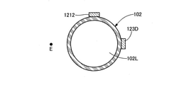
- FIG. 14 is a cross-sectional view of the catheter 100D in line DD of FIG.
- the recanalization catheter system 1D of the fifth embodiment includes the catheter 100D in place of the catheter 100C described in the fourth embodiment.
- the marker portion 12D of the catheter 100D further includes a third marker 123D and a fourth marker 124D in the configuration described in the fourth embodiment. In FIG. 13, the third marker 123D and the fourth marker 124D are shown by broken lines.
- Both the third marker 123D and the fourth marker 124D are flat plate-shaped (or arc-shaped along the outer peripheral surface of the first inner shaft 102) having a substantially rectangular shape. As shown in FIG. 13, both the third marker 123D and the fourth marker 124D are arranged between the first marker 121C and the second marker 122C in the circumferential direction of the first inner shaft 102. Further, as shown in FIG. 14, both the third marker 123D and the fourth marker 124D are on the opposite side of the side surface of the protrusion 109 from the side facing the extension line E of the central axis of the second lumen 103L. Is joined to the outer peripheral surface of the first inner shaft 102.
- the configuration of the catheter 100D can be variously changed, and the marker unit 12D may include the third marker 123D and the fourth marker 124D.
- the length (length in the X-axis direction) and the shape of the third marker 123D and the fourth marker 124D can be arbitrarily determined.
- the shapes of the third marker 123D and the fourth marker 124D may be different from the shapes of the sub-markers 1211 to 121n.
- the marker unit 12D may have only a single third marker 123D and may not have the fourth marker 124D.
- the marker unit 12D may further include fifth and sixth markers.
- the recanalization catheter system 1D provided with the catheter 100D of the fifth embodiment as described above can also achieve the same effects as those of the first and fourth embodiments described above.
- the marker portion 12D is further arranged between the first marker 121C and the second marker 122C in the circumferential direction of the shafts 101 to 104 (first inner shaft 102).
- the third marker 123D is provided, and is provided with the third marker 123D arranged on the side opposite to the side facing the extension line E of the central axis of the second lumen 103L. Therefore, in addition to the first and second markers 121C and 122C, the third marker 123D functions as a landmark to provide a catheter 100D that makes it easier to grasp the circumferential direction in the living lumen. can.
- FIG. 15 is a schematic bottom view of the distal end side of the catheter 100E of the sixth embodiment.
- the recanalization catheter system 1E of the sixth embodiment includes the catheter 100E in place of the catheter 100C described in the fourth embodiment.
- the marker portion 12E of the catheter 100E includes a first marker 121E in place of the first marker 121C.
- the first marker 121E is a member having a substantially rectangular flat plate shape (or an arc shape along the outer peripheral surface of the first inner shaft 102) extending from the tip fixing portion 128 to the base end fixing portion 129.
- the tip portion of the first marker 121E is joined to the tip fixing portion 128, and the proximal end portion of the first marker 121E is joined to the proximal end fixing portion 129.
- the configuration of the catheter 100E can be variously changed, and one of the first marker 121E and the second marker 122C (in the illustrated example, the second marker 122C) is configured by the sub-markers 1221 to 122m. Therefore, the shapes of the first marker 121E and the second marker 122C may be different.
- the recanalization catheter system 1E provided with the catheter 100E of the sixth embodiment as described above can also achieve the same effects as those of the first and fourth embodiments described above.
- FIG. 16 is a schematic bottom view of the distal end side of the catheter 100F of the seventh embodiment.
- the recanalization catheter system 1F of the seventh embodiment includes a catheter 100F instead of the catheter 100A described in the second embodiment.
- the catheter 100F includes a connecting portion 123F instead of the connecting portion 123 of the second embodiment.
- the connecting portion 123F is an annular member extending along the circumferential direction of the first inner shaft 102.
- the connecting portion 123F has a thin portion 123b on the side of the second lumen 103L facing the extension line E of the central axis, which is thinner than the other portions.
- the configuration of the catheter 100F can be variously changed, and the first marker 121 and the second marker 122 may be connected by using the connecting portion 123F having the thin-walled portion 123b.
- the recanalization catheter system 1F provided with the catheter 100F of the seventh embodiment as described above can also achieve the same effects as those of the first and second embodiments described above.
- FIG. 17 is a schematic bottom view of the distal end side of the catheter 100G of the eighth embodiment.
- the reopening catheter system 1G of the eighth embodiment includes a catheter 100G instead of the catheter 100A described in the second embodiment.
- the catheter 100G includes a connecting portion 123G instead of the connecting portion 123 of the second embodiment.
- the connecting portion 123G is an annular member extending along the circumferential direction of the first inner shaft 102.
- the connecting portion 123G has a narrow portion 123c on the side of the second lumen 103L facing the extension line E of the central axis, which is narrower in the X-axis direction than the other portions.
- the configuration of the catheter 100G can be variously changed, and the first marker 121 and the second marker 122 may be connected by using the connecting portion 123G having the narrow portion 123c.
- the recanalization catheter system 1G provided with the catheter 100G of the eighth embodiment as described above can also achieve the same effects as those of the first and second embodiments described above.
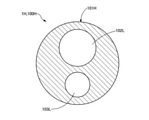
- FIG. 18 is a cross-sectional view of the catheter 100H of the ninth embodiment.
- FIG. 18 shows a cross-sectional view of the catheter 100H in line BB of FIG.
- the recanalization catheter system 1H of the ninth embodiment includes a catheter 100H in place of the catheter 100 described in the first embodiment.
- the catheter 100H does not have the outer shaft 101, the first inner shaft 102, the second inner shaft 103, the tip tip 104, the sealing member 114, and the blade 115 described in the first embodiment, and is a single shaft. It is composed of 101H.
- the shaft 101H has the same configuration as the shafts 101 to 104 of the first embodiment except that it is composed of a single member. That is, the first lumen 102L, the second lumen 103L, and the third lumen 104L are formed inside the shaft 101H. Further, the shaft 101H has a protrusion 109, a first opening 104a, a second opening 104b, a tip opening 103a, a base end side opening 103b, and an end surface 108.
- the marker portion 12 described in the first embodiment is provided on the side surface of the protruding portion 109 of the shaft 101H.
- the configuration of the catheter 100H can be variously changed, and may be configured by a single shaft 101H.
- the shaft 101H may include at least a part of the members omitted in the ninth embodiment (for example, the tip tip 104 on which the third lumen 104L is formed).
- the recanalization catheter system 1H provided with the catheter 100H of the ninth embodiment as described above can also achieve the same effect as that of the first embodiment described above.
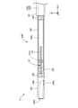
- FIG. 19 is a schematic side view of the distal end side of the catheter 100I of the tenth embodiment.
- the recanalization catheter system 1I of the tenth embodiment includes the catheter 100I in place of the catheter 100 described in the first embodiment.
- the catheter 100I does not have a second inner shaft 103, a second lumen 103L, a tip opening 103a, and a proximal opening 103b.
- the configuration of the catheter 100I can be changed in various ways, and the shafts 101 to 104 may be configured without the first lumen 102L. Even with the recanalization catheter system 1I provided with the catheter 100I of the tenth embodiment as described above, the operator can grasp the direction of the catheter 100I by the shape of the marker portion 12 shown in the image.
- the configuration of the recanalization catheter systems 1, 1A to 1I is shown.
- the configuration of the recanalization catheter system 1 can be changed in various ways.
- the imaging sensor 200 a sensor that acquires an image of a living tissue by means other than starting and receiving ultrasonic waves may be used.
- an OCT Optical Coherence Tomography
- a camera can be inserted to acquire an image of a living tissue in a blood vessel.
- the reopening catheter systems 1, 1A to 1I are configured as a system for opening a CTO using a plasma guide wire that ablate a living tissue using plasma without using a penetrating guide wire 400. May be good.
- the blade 115 is made of a conductive metal material and an electrode electrically connected to the blade 115 is provided on the tip end side of the outer shaft 101.
- the plasma guide wire can be used by connecting the electrode provided on the tip end side of the outer shaft 101 and the proximal end side of the blade 115 to the RF generator.
- the recanalization catheter systems 1, 1A to 1I may be used by other methods not described above.
- the recanalization catheter system may be used for blood vessels other than coronary arteries (eg, blood vessels in the lower extremities) or in living lumens other than blood vessels.
- the recanalization catheter system 1 may be used for other treatments and examinations other than opening the CTO.
- the catheter 100 configuration can be modified in various ways.
- the first lumen 102L and the second lumen 103L of the catheter 100 may have substantially the same diameter, and the first lumen 102L may be configured to have a smaller diameter than the second lumen 103L.
- the catheter 100 comprises a first lumen 102L and a second lumen 103L, as well as additional lumens for other medical devices or for simultaneous insertion of the delivery guide wire 70 and the penetration guide wire 400. You may.
- the portion of the first inner shaft 102 corresponding to the protruding portion 109 is preferably formed of polyamide from the viewpoint of achieving both ultrasonic transmission of the imaging sensor 200 and ensuring the wall thickness.
- the portion not corresponding to the protruding portion 109, the outer shaft 101, the second inner shaft 103, the sealing member 114, and the like are made of polytetrafluoroethylene (PTFE) from the viewpoint of ensuring rigidity.
- PTFE polytetrafluoroethylene
- Polyimide preferably formed from a copolymer (PFA) of ethylene tetrafluoride and perfluoroalkoxyethylene.
- the outer shaft 101 and the sealing member 114 may be formed of polyamide.
- the tip 104 is preferably made of polyurethane from the viewpoint of ensuring flexibility.
- the wall thickness of the portion of the first inner shaft 102 that does not correspond to the protruding portion 109 is preferably 10 microns or more for insulation from the conductive blade 115.
- the end surface 108 of the second inner shaft 103 may not be inclined and may be flat (perpendicular to the X-axis direction).
- the catheter may include a coil body made of a conductive metal material as a reinforcing member instead of the blade 115. Further, both the blade 115 and the coil body may be provided.
- the marker portion 12 may be coated with an insulating resin, or a chemical agent may be coated on the surface thereof.
- the first marker 121 and the second marker 122 may be configured so that the positions of the shafts 101 to 104 in the longitudinal direction are different and the shapes are different. Then, the operator can more easily grasp the circumferential orientation of the catheter 100.
- the marker unit 12 (first and second markers 121, 122) may be configured to have radiation opacity and an acoustic impedance different from that of the shaft. Then, the operator can visually recognize the marker portion 12 in both the X-ray image and the sensor image, so that the convenience can be improved.
- First marker 121a ... First intermediate part 122, 122C ... Second marker 122a ... Second intermediate part 123, 125, 126, 123F , 123G ... Connecting part 123D ... Third marker 123a, 125a, 126a, 127a ... Open part 123b ... Thin-walled part 123c ... Narrow part 124 ... Tip connecting part 124D ... Fourth marker 127 ... Base end connecting part 128 ... Tip fixing part 129 ... Base end fixing part 200 ... Imaging sensor 201 ... Transducer 202 ... Driving cable 203 ... Connector 300 ... Imaging console 302 ... Display 400 ... Penetration guide wire 1211-112n ... Submarker 1221-122m ... Submarker
Landscapes
- Health & Medical Sciences (AREA)
- Life Sciences & Earth Sciences (AREA)
- Biophysics (AREA)
- Pulmonology (AREA)
- Engineering & Computer Science (AREA)
- Anesthesiology (AREA)
- Biomedical Technology (AREA)
- Heart & Thoracic Surgery (AREA)
- Hematology (AREA)
- Animal Behavior & Ethology (AREA)
- General Health & Medical Sciences (AREA)
- Public Health (AREA)
- Veterinary Medicine (AREA)
- Media Introduction/Drainage Providing Device (AREA)
Priority Applications (2)
| Application Number | Priority Date | Filing Date | Title |
|---|---|---|---|
| JP2022548277A JP7487319B2 (ja) | 2020-09-08 | 2020-09-08 | カテーテル、及び、再開通カテーテルシステム |
| PCT/JP2020/033998 WO2022054141A1 (ja) | 2020-09-08 | 2020-09-08 | カテーテル、及び、再開通カテーテルシステム |
Applications Claiming Priority (1)
| Application Number | Priority Date | Filing Date | Title |
|---|---|---|---|
| PCT/JP2020/033998 WO2022054141A1 (ja) | 2020-09-08 | 2020-09-08 | カテーテル、及び、再開通カテーテルシステム |
Publications (1)
| Publication Number | Publication Date |
|---|---|
| WO2022054141A1 true WO2022054141A1 (ja) | 2022-03-17 |
Family
ID=80630421
Family Applications (1)
| Application Number | Title | Priority Date | Filing Date |
|---|---|---|---|
| PCT/JP2020/033998 Ceased WO2022054141A1 (ja) | 2020-09-08 | 2020-09-08 | カテーテル、及び、再開通カテーテルシステム |
Country Status (2)
| Country | Link |
|---|---|
| JP (1) | JP7487319B2 (https=) |
| WO (1) | WO2022054141A1 (https=) |
Citations (7)
| Publication number | Priority date | Publication date | Assignee | Title |
|---|---|---|---|---|
| JP2005103018A (ja) * | 2003-09-30 | 2005-04-21 | Terumo Corp | 体腔内治療診断システム |
| JP2007130116A (ja) * | 2005-11-09 | 2007-05-31 | Kaneka Corp | カテーテル |
| US20080097404A1 (en) * | 2006-08-16 | 2008-04-24 | Abbott Laboratories | Catheter having markers to indicate rotational orientation |
| WO2012014860A1 (ja) * | 2010-07-28 | 2012-02-02 | ニプロ株式会社 | 医療用カテーテル |
| JP2014100330A (ja) * | 2012-11-20 | 2014-06-05 | Terumo Corp | カテーテル用チューブの製造方法 |
| JP2017153621A (ja) * | 2016-02-29 | 2017-09-07 | テルモ株式会社 | 医療用デバイス |
| JP2018191883A (ja) * | 2017-05-16 | 2018-12-06 | テルモ株式会社 | 医療用長尺体 |
Family Cites Families (3)
| Publication number | Priority date | Publication date | Assignee | Title |
|---|---|---|---|---|
| WO2006076409A2 (en) | 2005-01-11 | 2006-07-20 | Volcano Corporation | Vascular image co-registration |
| JP2009000389A (ja) | 2007-06-22 | 2009-01-08 | Kaneka Corp | 柔軟性スリットマーカー及びそれを備えたカテーテル |
| EP3618723B1 (en) | 2017-09-15 | 2024-07-24 | INFRAREDEX, Inc. | Imaging catheter |
-
2020
- 2020-09-08 JP JP2022548277A patent/JP7487319B2/ja active Active
- 2020-09-08 WO PCT/JP2020/033998 patent/WO2022054141A1/ja not_active Ceased
Patent Citations (7)
| Publication number | Priority date | Publication date | Assignee | Title |
|---|---|---|---|---|
| JP2005103018A (ja) * | 2003-09-30 | 2005-04-21 | Terumo Corp | 体腔内治療診断システム |
| JP2007130116A (ja) * | 2005-11-09 | 2007-05-31 | Kaneka Corp | カテーテル |
| US20080097404A1 (en) * | 2006-08-16 | 2008-04-24 | Abbott Laboratories | Catheter having markers to indicate rotational orientation |
| WO2012014860A1 (ja) * | 2010-07-28 | 2012-02-02 | ニプロ株式会社 | 医療用カテーテル |
| JP2014100330A (ja) * | 2012-11-20 | 2014-06-05 | Terumo Corp | カテーテル用チューブの製造方法 |
| JP2017153621A (ja) * | 2016-02-29 | 2017-09-07 | テルモ株式会社 | 医療用デバイス |
| JP2018191883A (ja) * | 2017-05-16 | 2018-12-06 | テルモ株式会社 | 医療用長尺体 |
Also Published As
| Publication number | Publication date |
|---|---|
| JP7487319B2 (ja) | 2024-05-20 |
| JPWO2022054141A1 (https=) | 2022-03-17 |
Similar Documents
| Publication | Publication Date | Title |
|---|---|---|
| JP7061682B2 (ja) | カテーテル、及び、再開通カテーテルシステム | |
| US6315732B1 (en) | Imaging catheter and methods of use for ultrasound-guided ablation | |
| EP2091439B1 (en) | Devices for creating passages and sensing for blood vessels | |
| JP3413175B2 (ja) | 固定型中心コア及び先端を持つ超音波撮像用ガイドワイヤ | |
| JP2004097286A (ja) | カテーテル | |
| JP7465824B2 (ja) | カテーテル | |
| JP2004532691A (ja) | 治療のための超音波エンドエフェクタの案内 | |
| JP2023004052A (ja) | カテーテル | |
| JP3628385B2 (ja) | カテーテルチューブ | |
| JP4815621B2 (ja) | 超音波プローブ及び超音波診断装置 | |
| JP2021145860A (ja) | 医療器具 | |
| JP3727407B2 (ja) | カテーテルチューブ | |
| JP7487319B2 (ja) | カテーテル、及び、再開通カテーテルシステム | |
| JP7555421B2 (ja) | カテーテル、及び、再開通カテーテルシステム | |
| CN1065999A (zh) | 内窥式超声波引导导管 | |
| JP5171985B2 (ja) | 超音波カテーテル | |
| JP4955161B2 (ja) | 超音波カテーテル | |
| JP3641427B2 (ja) | 内視鏡下外科手術用超音波探触子 | |
| JPH08155031A (ja) | ケーブル付設カテーテル及びこれを用いた機能部品付カテーテル | |
| WO2024241378A1 (ja) | 医療デバイス、及び、医療デバイスの製造方法 | |
| JP2024077665A (ja) | カテーテル | |
| WO2026003950A1 (ja) | 医療デバイス | |
| JP2000271123A (ja) | 体腔内超音波プローブ | |
| JPH09154950A (ja) | カテーテルチューブ |
Legal Events
| Date | Code | Title | Description |
|---|---|---|---|
| 121 | Ep: the epo has been informed by wipo that ep was designated in this application |
Ref document number: 20953209 Country of ref document: EP Kind code of ref document: A1 |
|
| ENP | Entry into the national phase |
Ref document number: 2022548277 Country of ref document: JP Kind code of ref document: A |
|
| NENP | Non-entry into the national phase |
Ref country code: DE |
|
| 122 | Ep: pct application non-entry in european phase |
Ref document number: 20953209 Country of ref document: EP Kind code of ref document: A1 |