WO2022049665A1 - 軸流ファン、及び、空気調和機の室外機 - Google Patents
軸流ファン、及び、空気調和機の室外機 Download PDFInfo
- Publication number
- WO2022049665A1 WO2022049665A1 PCT/JP2020/033229 JP2020033229W WO2022049665A1 WO 2022049665 A1 WO2022049665 A1 WO 2022049665A1 JP 2020033229 W JP2020033229 W JP 2020033229W WO 2022049665 A1 WO2022049665 A1 WO 2022049665A1
- Authority
- WO
- WIPO (PCT)
- Prior art keywords
- edge portion
- axial
- fan
- angle
- blade
- Prior art date
- Legal status (The legal status is an assumption and is not a legal conclusion. Google has not performed a legal analysis and makes no representation as to the accuracy of the status listed.)
- Ceased
Links
Images












Classifications
-
- F—MECHANICAL ENGINEERING; LIGHTING; HEATING; WEAPONS; BLASTING
- F04—POSITIVE - DISPLACEMENT MACHINES FOR LIQUIDS; PUMPS FOR LIQUIDS OR ELASTIC FLUIDS
- F04D—NON-POSITIVE-DISPLACEMENT PUMPS
- F04D29/00—Details, component parts, or accessories
- F04D29/26—Rotors specially for elastic fluids
- F04D29/32—Rotors specially for elastic fluids for axial flow pumps
- F04D29/38—Blades
- F04D29/384—Blades characterised by form
-
- F—MECHANICAL ENGINEERING; LIGHTING; HEATING; WEAPONS; BLASTING
- F24—HEATING; RANGES; VENTILATING
- F24F—AIR-CONDITIONING; AIR-HUMIDIFICATION; VENTILATION; USE OF AIR CURRENTS FOR SCREENING
- F24F1/00—Room units for air-conditioning, e.g. separate or self-contained units or units receiving primary air from a central station
- F24F1/06—Separate outdoor units, e.g. outdoor unit to be linked to a separate room comprising a compressor and a heat exchanger
- F24F1/38—Fan details of outdoor units, e.g. bell-mouth shaped inlets or fan mountings
-
- F—MECHANICAL ENGINEERING; LIGHTING; HEATING; WEAPONS; BLASTING
- F05—INDEXING SCHEMES RELATING TO ENGINES OR PUMPS IN VARIOUS SUBCLASSES OF CLASSES F01-F04
- F05D—INDEXING SCHEME FOR ASPECTS RELATING TO NON-POSITIVE-DISPLACEMENT MACHINES OR ENGINES, GAS-TURBINES OR JET-PROPULSION PLANTS
- F05D2240/00—Components
- F05D2240/20—Rotors
- F05D2240/30—Characteristics of rotor blades, i.e. of any element transforming dynamic fluid energy to or from rotational energy and being attached to a rotor
- F05D2240/303—Characteristics of rotor blades, i.e. of any element transforming dynamic fluid energy to or from rotational energy and being attached to a rotor related to the leading edge of a rotor blade
-
- F—MECHANICAL ENGINEERING; LIGHTING; HEATING; WEAPONS; BLASTING
- F05—INDEXING SCHEMES RELATING TO ENGINES OR PUMPS IN VARIOUS SUBCLASSES OF CLASSES F01-F04
- F05D—INDEXING SCHEME FOR ASPECTS RELATING TO NON-POSITIVE-DISPLACEMENT MACHINES OR ENGINES, GAS-TURBINES OR JET-PROPULSION PLANTS
- F05D2240/00—Components
- F05D2240/20—Rotors
- F05D2240/30—Characteristics of rotor blades, i.e. of any element transforming dynamic fluid energy to or from rotational energy and being attached to a rotor
- F05D2240/304—Characteristics of rotor blades, i.e. of any element transforming dynamic fluid energy to or from rotational energy and being attached to a rotor related to the trailing edge of a rotor blade
-
- F—MECHANICAL ENGINEERING; LIGHTING; HEATING; WEAPONS; BLASTING
- F05—INDEXING SCHEMES RELATING TO ENGINES OR PUMPS IN VARIOUS SUBCLASSES OF CLASSES F01-F04
- F05D—INDEXING SCHEME FOR ASPECTS RELATING TO NON-POSITIVE-DISPLACEMENT MACHINES OR ENGINES, GAS-TURBINES OR JET-PROPULSION PLANTS
- F05D2250/00—Geometry
- F05D2250/70—Shape
- F05D2250/71—Shape curved
-
- F—MECHANICAL ENGINEERING; LIGHTING; HEATING; WEAPONS; BLASTING
- F05—INDEXING SCHEMES RELATING TO ENGINES OR PUMPS IN VARIOUS SUBCLASSES OF CLASSES F01-F04
- F05D—INDEXING SCHEME FOR ASPECTS RELATING TO NON-POSITIVE-DISPLACEMENT MACHINES OR ENGINES, GAS-TURBINES OR JET-PROPULSION PLANTS
- F05D2250/00—Geometry
- F05D2250/70—Shape
- F05D2250/71—Shape curved
- F05D2250/711—Shape curved convex
-
- F—MECHANICAL ENGINEERING; LIGHTING; HEATING; WEAPONS; BLASTING
- F05—INDEXING SCHEMES RELATING TO ENGINES OR PUMPS IN VARIOUS SUBCLASSES OF CLASSES F01-F04
- F05D—INDEXING SCHEME FOR ASPECTS RELATING TO NON-POSITIVE-DISPLACEMENT MACHINES OR ENGINES, GAS-TURBINES OR JET-PROPULSION PLANTS
- F05D2250/00—Geometry
- F05D2250/70—Shape
- F05D2250/74—Shape given by a set or table of xyz-coordinates
Definitions
- the present disclosure relates to an axial fan and an outdoor unit of an air conditioner having an axial fan.
- the conventional axial fan is equipped with a plurality of blades along the peripheral surface of the cylindrical boss, and the blades rotate according to the rotational force applied to the boss to convey the fluid.
- the fluid existing between the blades collides with the blade surface due to the rotation of the blades.
- the pressure rises on the surface where the fluid collides, and the fluid is pushed out and moved in the direction of the rotation axis, which is the central axis when the blade rotates.
- the shape of the center warp line in the cross section when the blade is cut on the cylindrical surface centered on the rotation axis is the straight portion provided on the blade leading edge side and the blade trailing edge side.
- an axial flow fan having a shape provided with a curved portion provided in see, for example, Patent Document 1.
- This straight portion is formed so as to be substantially in the same direction as the non-collision inflow direction of gas to the blade surface, and the curved portion is formed so that the outflow direction of gas from the blade surface and the straight portion are continuous. Has been done.
- the linear portion and the curved portion have such a shape, so that the tangential direction of the blade front end portion almost coincides with the non-collision inflow direction in almost the entire radial direction from the rotation axis. It is said that. Therefore, in the axial flow fan of Patent Document 1, the gas flowing from the front end portion of the blade flows along the straight portion and is guided to the curved portion, so that the flow can be close to the ideal flow without loss. ..
- the blade load of the axial flow fan of Patent Document 1 cannot be adjusted in the radial direction, and the blade load on the inner peripheral side of the axial flow fan is not sufficiently increased with respect to the outer peripheral side of the axial flow fan.
- the air flow on the blade surface flows to the outer peripheral side of the axial fan under the influence of the partition plate of the machine. Therefore, the flow of air blown out from the axial flow fan is located so that the maximum value of the wind speed distribution in the radial direction is concentrated on the outermost circumference or near the outer circumference, and a structure such as a fan grill located on the downstream side of the axial flow fan.
- the noise of the outdoor unit of the air conditioner increases because the air concentrated in the air collides with the air conditioner.
- the present disclosure is for solving the above-mentioned problems, an axial fan in which noise generated when air is blown out by driving an axial fan is suppressed, and an outdoor unit of an air conditioner.
- the purpose is to provide.
- the axial flow fan according to the present disclosure is an axial flow fan used in an outdoor unit of an air conditioner, and includes a hub that is rotationally driven to form a rotating shaft, and a blade formed around the hub.
- It has an inner peripheral edge portion that is connected to and forms an edge portion on the inner peripheral side of the outermost periphery of the blade, and has a trailing edge portion in the cross section of the blade along the axial direction of the rotation axis and the circumferential direction of the axial flow fan.
- the angle between the virtual line parallel to the axis of rotation that intersects with the wing and the virtual line indicating the direction in which the trailing edge is facing is defined as the exit angle of the wing, and the horizontal axis is outside the inner peripheral edge of the trailing edge.
- the first line diagram shows the position of the size of the exit angle of the trailing edge portion in the inner peripheral edge portion and the exit angle of the trailing edge portion in the outer peripheral edge portion in the first diagram. It has a wing formed so as to have a lower convex portion that is convex downward from the first virtual line diagram represented by a linear straight line connecting the position of the size of.
- the outdoor unit of the air conditioner according to the present disclosure is provided at a housing in which an air outlet is formed on a wall portion, an axial fan having the above configuration arranged inside the housing, and an air outlet. It is equipped with a bell mouth that surrounds the outer circumference of the axial flow fan.
- the outdoor unit of the axial fan and the air conditioner is formed so that the first line diagram has a lower convex portion that is convex downward from the first virtual line diagram.
- the wing having the region has a portion having a smaller exit angle on the inner peripheral side of the wing by having the lower convex portion as compared with the wing forming the first virtual line. Therefore, the wing loading becomes large in the portion constituting the lower convex portion. Therefore, the axial flow fan can attract the air flow on the blade surface to the inner peripheral side by sufficiently increasing the blade load on the inner peripheral side by the lower convex portion with respect to the outer peripheral side.
- the air flow blown out from the air flow has a uniform wind speed distribution in the radial direction.
- a structure such as a fan grill located on the downstream side of the axial fan.
- FIG. 1 It is a schematic diagram of the air conditioner which concerns on Embodiment 1.
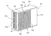
- FIG. It is a perspective view of the outdoor unit which concerns on Embodiment 1.
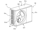
- FIG. It is a perspective view when the outdoor unit which concerns on Embodiment 1 is seen from the outlet side.
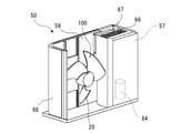
- FIG. It is a perspective view which shows the internal structure by removing the front wall part and the like from an outdoor unit.
- It is a conceptual diagram for demonstrating the internal structure of an outdoor unit from the top surface side.
- It is a front view which shows the schematic structure of the axial flow fan which concerns on Embodiment 1.
- FIG. It is a front view which shows the schematic structure of the blade of the axial flow fan which concerns on Embodiment 1.
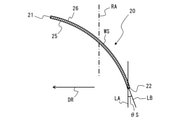
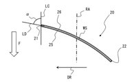
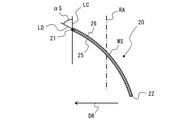
- FIG. 7 is a cross-sectional view taken along the line AA of the wing of FIG. It is a cross-sectional view taken along the line AA of the blade when it has an exit angle ⁇ S. It is a cross-sectional view taken along the line AA of the blade when it has an exit angle ⁇ L.
- FIG. 3 is a top view conceptually showing an outdoor unit provided with an axial fan according to the first embodiment. It is a front view which shows the schematic structure of the blade of the axial flow fan which concerns on Embodiment 2.
- FIG. 7 is a cross-sectional view taken along the line AA of the blades of FIGS. 7 and 19. It is a cross-sectional view taken along the line AA of a wing when it has an entrance angle ⁇ S. It is a cross-sectional view taken along the line AA of a wing when it has an entrance angle ⁇ L. It is a figure which shows the relationship of the wing in FIG. 1 and FIG.
- FIG. 3 is a top view conceptually showing an outdoor unit provided with an axial fan according to the second embodiment.
- FIG. 3 is a top view conceptually showing an outdoor unit provided with an axial fan according to the third embodiment. It is a figure which shows the relationship of the blade in FIG. 1 and FIG. 2 of the axial flow fan which concerns on Embodiment 4.
- FIG. It is a figure which shows the relationship between the distance in the radial direction of the axial flow fan which concerns on Embodiment 5 and the size of the outlet angle ⁇ . It is a top view which conceptually showed the outdoor unit equipped with the axial flow fan which concerns on a comparative example.
- FIG. 3 is a top view conceptually showing an outdoor unit provided with an axial fan according to the fifth embodiment. It is a top view which conceptually showed the outdoor unit which concerns on Embodiment 6. It is a top view which conceptually showed the outdoor unit which concerns on Embodiment 7. It is a top view which conceptually showed the outdoor unit which concerns on Embodiment 8. It is a top view which conceptually showed the modification of the outdoor unit which concerns on Embodiment 8.
- FIG. 1 is a schematic diagram of the air conditioner 70 according to the first embodiment.
- the air conditioner 70 includes a refrigerant circuit 71 in which a compressor 64, a condenser 72, an expansion valve 74, and an evaporator 73 are connected in order by a refrigerant pipe.
- the condenser 72 is provided with a condenser fan 72a that blows heat exchange air to the condenser 72.
- the evaporator 73 is provided with an evaporator fan 73a that blows heat exchange air to the evaporator 73.
- the air conditioner 70 may be configured to provide a flow path switching device such as a four-way valve for switching the flow of the refrigerant in the refrigerant circuit 71 to switch between heating operation and cooling operation.
- FIG. 2 is a perspective view of the outdoor unit 50 according to the first embodiment.
- FIG. 3 is a perspective view of the outdoor unit 50 according to the first embodiment when viewed from the outlet 53 side.
- FIG. 4 is a perspective view showing an internal configuration by removing the front wall portion 51b and the like from the outdoor unit 50.
- FIG. 5 is a conceptual diagram for explaining the internal configuration of the outdoor unit 50 from the upper surface side. Note that FIG. 3 omits the illustration of the fan grill 54 provided in the outlet 53 in order to explain the configuration of the outdoor unit 50 in the outlet 53.
- the outdoor unit 50 has a housing 51 that constitutes the outer shell of the outdoor unit 50.
- the housing 51 is formed in the shape of a rectangular parallelepiped box.
- the housing 51 includes a front wall portion 51b that constitutes the front surface of the housing 51, a back wall portion 51d that constitutes the back surface of the housing 51, a top plate 51e that constitutes the upper surface of the housing 51, and the housing 51. It has a bottom plate 51f constituting the lower surface, and a pair of left and right side walls 51a and side walls 51c constituting the side surfaces of the housing 51.
- the side wall 51a of the housing 51 is formed with an opening 51a1 for sucking air from the outside, and the back wall portion 51d of the housing 51 has an opening for sucking air from the outside (not shown). Is formed. Further, the front wall portion 51b of the housing 51 is formed with an outlet 53 as an opening for blowing air from the inside of the housing 51 to the outside.
- the air outlet 53 is covered with a fan grill 54, whereby the outdoor unit 50 prevents an object or the like outside the housing 51 from coming into contact with the axial fan 100, and safety is achieved.
- the arrow AR in FIG. 3 indicates the flow of air.
- the fan grill 54 has a plurality of crosspieces 54a extending in the horizontal direction.
- the crosspiece 54a is a part of the crosspiece extending in the horizontal direction among the various types of crosspieces.
- the crosspiece 54a is formed in a plate shape extending between the side wall 51a side and the side wall 51c side.
- a plurality of crosspieces 54a are arranged so as to be spaced apart from each other in the vertical direction. Air discharged from the inside of the outdoor unit 50 to the outside by driving the axial fan 100 passes between the adjacent crosspieces 54a in the fan grill 54.
- a rotatable axial flow fan 100 and a motor 61 for rotating the axial flow fan 100 are housed inside the housing 51.
- the axial fan 100 rotates around the rotary shaft RS to form an air flow in which air flows from the outside of the housing 51 into the inside and the air flows out from the inside of the housing 51 to the outside.
- the axial flow fan 100 has a hub 10 connected to the rotating shaft 62 of the motor 61, and a plurality of blades 20 provided on the peripheral edge of the hub 10.
- the axial fan 100 is connected to the motor 61, which is a drive source arranged on the back wall portion 51d side with respect to the axial fan 100, via a rotary shaft 62, and is rotationally driven by the motor 61.
- the motor 61 applies a driving force to the axial fan 100.
- the motor 61 is attached to the motor support 69.
- the motor support 69 is arranged between the motor 61 and the heat exchanger 68.
- the inside of the housing 51 is divided into a blower chamber 56 in which the axial flow fan 100 is installed and a machine room 57 in which the compressor 64 and the like are installed by a partition plate 51 g which is a wall body.
- the blower chamber 56 is a space surrounded by a side wall 51a, a partition plate 51g, a front wall portion 51b, a top plate 51e, and a bottom plate 51f.
- the machine room 57 is a space surrounded by a side wall 51c, a partition plate 51g, a front wall portion 51b, a back wall portion 51d, a top plate 51e, and a bottom plate 51f.
- the side wall 51a faces the partition plate 51g with the axial fan 100 in between.
- the top plate 51e faces the bottom plate 51f with the axial fan 100 in between.
- the heat exchanger 68 provided on the suction side of the axial flow fan 100 has a plurality of fins arranged side by side so that the plate-shaped surfaces are parallel to each other, and each fin in the parallel arrangement direction. It is equipped with a heat transfer tube that penetrates through. A refrigerant circulating in the refrigerant circuit 71 circulates in the heat transfer tube.
- a plurality of heat transfer tubes provided in the vertical direction extend in an L shape toward the side wall 51a side and the back wall portion 51d side of the housing 51, respectively.
- the shape of the heat exchanger 68 is not limited to this shape.
- the heat exchanger 68 may be formed in a substantially I shape, for example, along the back surface side inside the blower chamber 56 in which the back wall portion 51d is formed. Further, the heat exchanger 68 may be a so-called finless heat exchanger having no fins through which the heat transfer tube penetrates.
- the heat exchanger 68 functions as an evaporator 73 during the heating operation and as a condenser 72 during the cooling operation.
- the heat exchanger 68 of the outdoor unit 50 is connected to the compressor 64 via piping or the like, and is further connected to the heat exchanger (not shown) on the indoor side and the expansion valve 74 or the like to form the air conditioner 70. It constitutes a refrigerant circuit 71.
- the heat exchanger 68 of the outdoor unit 50 constitutes the condenser 72 or the evaporator 73 shown in FIG. Further, as shown in FIG. 4, a board box 66 is arranged in the machine room 57, and the equipment mounted in the outdoor unit 50 is controlled by the control board 67 provided in the board box 66. ..
- a bell mouth 63 formed in a cylindrical shape is arranged inside the housing 51 on the radial outer side of the axial flow fan 100 arranged in the blower chamber 56. ing.
- the bell mouth 63 is provided at the outlet 53 and is arranged so as to surround the outer periphery of the axial flow fan 100.
- the bell mouth 63 surrounds the outer peripheral side of the axial flow fan 100 and regulates the flow of air formed by the axial flow fan 100 and the like.
- the bell mouth 63 is located outside the outer peripheral end of the blade 20, and is formed in an annular shape along the rotation direction of the axial fan 100.
- a partition plate 51g is located on one side of the bell mouth 63, and a part of the side wall 51a of the housing 51 is located on the other side.
- one end of the bell mouth 63 is connected to the front wall portion 51b of the outdoor unit 50 so as to surround the outer circumference of the outlet 53.
- the bell mouth 63 is integrally formed with the front wall portion 51b, but is not limited to the above configuration, but is formed as a separate body from the front wall portion 51b and connected to the front wall portion 51b. It may be prepared.
- the bell mouth 63 configures the air flow path between the suction side and the blow side of the bell mouth 63 as an air passage near the outlet 53. That is, the air passage in the vicinity of the air outlet 53 is separated from other spaces in the air blowing chamber 56 by the bell mouth 63.
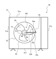
- FIG. 6 is a front view showing a schematic configuration of the axial flow fan 100 according to the first embodiment.
- the rotation direction DR indicated by the arrow in the figure indicates the direction in which the axial fan 100 rotates.
- the reverse rotation direction OD indicated by the arrow in the figure indicates a direction opposite to the direction in which the axial flow fan 100 rotates.
- the circumferential direction CD indicated by the double-headed arrow in the figure indicates the circumferential direction of the axial flow fan 100.
- the circumferential CD includes a rotational DR and a reverse rotational OD.
- the axial fan 100 is a device that forms a fluid flow. As described above, the axial fan 100 is used in the outdoor unit 50 of the air conditioner 70.
- the axial flow fan 100 forms a fluid flow by rotating in the rotation direction DR about the rotation axis RA.
- the fluid is, for example, a gas such as air.
- the back side with respect to the paper surface of FIG. 6 is the upstream side with respect to the axial flow fan 100 in the fluid flow direction, and the front side with respect to the paper surface of FIG. 6 is with respect to the axial flow fan 100 in the fluid flow direction. It is on the downstream side.
- the upstream side with respect to the axial fan 100 is the air suction side with respect to the axial fan 100, and the downstream side with respect to the axial fan 100 is the air outlet side with respect to the axial fan 100.
- the axial flow fan 100 includes a hub 10 provided on the rotary shaft RA, and a plurality of blades 20 connected to the hub 10.
- the axial fan 100 includes a so-called bossless type fan in which the front edge side and the trailing edge side of adjacent blades 20 of a plurality of blades 20 are connected so as to form a continuous surface without a boss.
- the hub 10 is connected to a rotating shaft of a drive source such as a motor (not shown).
- the hub 10 may be configured in a cylindrical shape or a plate shape, for example.
- the hub 10 may be connected to the rotation shaft of the drive source as described above, and its shape is not limited.
- the hub 10 is rotationally driven by a motor (not shown) or the like to form a rotary shaft RA.
- the hub 10 rotates about the rotation axis RA.
- the rotation direction DR of the axial fan 100 is a counterclockwise direction as shown by an arrow in FIG.
- the rotation direction DR of the axial fan 100 is not limited to the counterclockwise direction.
- the hub 10 may be rotated clockwise by changing the mounting angle of the blade 20 or the direction of the blade 20.
- the wings 20 are formed around the hub 10 and are formed so as to extend radially outward from the hub 10.
- the plurality of blades 20 are arranged radially outward from the hub 10.
- the plurality of wings 20 are provided apart from each other in the circumferential direction CD.
- the axial fan 100 having three blades 20 is exemplified, but the number of blades 20 is not limited to three.
- the wing 20 has a leading edge portion 21, a trailing edge portion 22, an outer peripheral edge portion 23, and an inner peripheral edge portion 24.
- the leading edge portion 21 forms an edge portion on the forward side of the rotation direction DR in the wing 20. That is, the leading edge portion 21 is located forward with respect to the trailing edge portion 22 in the rotation direction DR.
- the leading edge portion 21 is located upstream of the trailing edge portion 22 in the direction in which the generated fluid flows.
- the trailing edge portion 22 forms an edge portion on the wing 20 opposite to the rotation direction DR. That is, the trailing edge portion 22 is located rearward with respect to the leading edge portion 21 in the rotation direction DR. The trailing edge portion 22 is located downstream of the leading edge portion 21 in the direction in which the generated fluid flows.
- the axial flow fan 100 has a leading edge portion 21 as a blade end portion facing the rotation direction DR of the axial flow fan 100, and a trailing edge portion 22 as a blade end portion opposite to the front edge portion 21 in the rotation direction DR. have.
- the outer peripheral edge portion 23 forms an edge portion on the outer peripheral side (Y2 side) of the wing 20.
- the outer peripheral edge portion 23 is a portion extending back and forth in the rotation direction DR so as to connect the outermost peripheral portion of the leading edge portion 21 and the outermost peripheral portion of the trailing edge portion 22.
- the outer peripheral edge portion 23 constitutes an end portion on the outer peripheral side in the radial direction (Y-axis direction) in the axial flow fan 100.
- the outer peripheral edge portion 23 is formed in an arc shape when viewed in a direction parallel to the rotation axis RA.
- the outer peripheral edge portion 23 is not limited to the configuration formed in an arc shape when viewed in a direction parallel to the rotation axis RA.
- the length of the outer peripheral edge portion 23 in the circumferential direction CD is longer than the length of the inner peripheral edge portion 24 in the circumferential direction CD.
- the relationship between the lengths of the outer peripheral edge portion 23 and the inner peripheral edge portion 24 in the circumferential direction CD is not limited to the configuration, and the length of the outer peripheral edge portion 23 and the length of the inner peripheral edge portion 24 are the same. In other words, the length of the inner peripheral edge portion 24 may be formed longer than the length of the outer peripheral edge portion 23.
- the inner peripheral edge portion 24 forms an edge portion on the inner peripheral side (Y1 side) of the outermost peripheral portion of the wing 20.
- the inner peripheral edge portion 24 is a portion extending back and forth in the rotation direction DR so as to connect the innermost peripheral portion of the leading edge portion 21 and the innermost peripheral portion of the trailing edge portion 22.
- the inner peripheral edge portion 24 constitutes an end portion on the inner peripheral side in the radial direction (Y-axis direction) in the axial flow fan 100.
- the inner peripheral edge portion 24 is formed in an arc shape when viewed in a direction parallel to the rotation axis RA.
- the inner peripheral edge portion 24 is not limited to the configuration formed in an arc shape when viewed in a direction parallel to the rotation axis RA.
- the inner peripheral edge portion 24 of the wing 20 is connected to the hub 10, such as being integrally formed with the hub 10.
- the inner peripheral edge portion 24 of the wing 20 is integrally formed with the outer peripheral wall of the hub 10 formed in a cylindrical shape.
- the wing 20 is formed so as to be inclined with respect to a plane perpendicular to the rotation axis RA.
- the blade 20 conveys the fluid by pushing the fluid existing between the blades 20 with the blade surface as the axial flow fan 100 rotates.
- the surface of the blade surface where the fluid is pushed and the pressure rises is referred to as the positive pressure surface 25, and the surface which is the back surface of the positive pressure surface 25 and the pressure decreases is referred to as the negative pressure surface 26.
- the surface on the upstream side of the blade 20 is the negative pressure surface 26 and the surface on the downstream side is the positive pressure surface 25 with respect to the flow direction of the fluid.
- the front surface of the wing 20 is the positive pressure surface 25, and the back surface of the wing 20 is the negative pressure surface 26.
- FIG. 7 is a front view showing a schematic configuration of the blade 20 of the axial fan 100 according to the first embodiment.
- FIG. 8 is a cross-sectional view taken along the line AA of the wing 20 of FIG. Note that FIG. 7 shows only one of the plurality of wings 20 and omits the other wings 20 in order to explain the configuration of the wings 20.
- the AA line cross section shown in FIG. 8 is the wing cross section WS of the wing 20 along the arc passing through the leading edge portion 21 and the trailing edge portion 22 at a specific position in the radial direction about the rotation axis RS. be.
- the white arrow F shown in FIG. 8 indicates the direction in which the air flows.
- the wing cross section WS is an arc-shaped cross section portion passing through the leading edge portion 21 and the trailing edge portion 22 in a plan view in which the wing 20 is viewed parallel to the axial direction of the rotation axis RS.
- the wing cross section WS shown in FIG. 8 is a cross-sectional view of the wing cross section WS as viewed in the radial direction of the wing 20. That is, the blade cross section WS shown in FIG. 8 is a cross section of the blade 20 in the axial direction of the rotating shaft RA and along the circumferential direction CD of the axial flow fan 100.
- the blade 20 is formed so that the positive pressure surface 25 side is concave and the negative pressure surface 26 side is convex. That is, the blade 20 is curved so as to be convex in the direction opposite to the rotation direction DR of the axial flow fan 100 and on the upstream side of the air flow, and is warped.
- the angle between the virtual line LA parallel to the rotation axis RA intersecting the trailing edge portion 22 and the virtual line LB indicating the direction in which the trailing edge portion 22 is facing is set to the angle of the wing 20. It is defined as the exit angle ⁇ .
- the outlet angle ⁇ is an angle between the virtual line LA and the virtual line LB in the blade cross section WS of the blade 20, is located on the downstream side of the airflow with respect to the virtual line LB, and is , The angle of the region located on the opposite side of the rotation direction DR with respect to the virtual line LA.
- the exit angle ⁇ forms an angle of 90 degrees or less.
- FIG. 9 is a sectional view taken along line AA of the blade 20 when the outlet angle ⁇ S is provided.
- FIG. 10 is a sectional view taken along line AA of the blade 20 when the blade 20 has an outlet angle ⁇ L.
- the wing loading is the pressure at which the wing 20 pushes out air.
- the exit angle ⁇ S is smaller than the exit angle ⁇ L, and the exit angle ⁇ L is larger than the exit angle ⁇ S (exit angle ⁇ S ⁇ exit angle ⁇ L).
- the blade cross section WS of the blade 20 forming the outlet angle ⁇ S is in a state where the positive pressure surface 25 of the blade 20 stands up with respect to the rotation direction DR as compared with the blade cross section WS of the blade 20 forming the outlet angle ⁇ L.
- the positive pressure surface 25 has an angle close to a right angle with respect to the rotation direction DR. Therefore, the portion of the blade 20 forming the outlet angle ⁇ S has a larger blade load than the portion of the blade 20 forming the outlet angle ⁇ L.
- the blade cross section WS of the blade 20 forming the outlet angle ⁇ L is in a state where the positive pressure surface 25 of the blade 20 lies down with respect to the rotation direction DR, as compared with the blade cross section WS of the blade 20 forming the outlet angle ⁇ S. That is, the positive pressure surface 25 has an angle close to parallel to the rotation direction DR. Therefore, the portion of the blade 20 forming the outlet angle ⁇ L has a smaller blade load than the portion of the blade 20 forming the outlet angle ⁇ S.
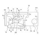
- FIG. 11 is a top view conceptually showing an outdoor unit 50L provided with an axial fan 100L according to a comparative example.
- FIG. 12 is a diagram showing the relationship between the radial distance of the axial flow fan 100L according to the comparative example and the size of the outlet angle ⁇ .
- the axial flow fan 100 is shown as a shape when rotationally projected onto a meridional surface including a rotation axis RA and a blade 20.
- the horizontal axis is the radial distance of the axial flow fan 100L from the inner peripheral edge portion 24 to the outer peripheral edge portion 23 of the trailing edge portion 22, and the vertical axis is the size of the exit angle ⁇ . It represents the magnitude of the exit angle ⁇ with respect to the radial distance from the inner peripheral edge portion 24 of 22.
- the axial flow fan 100L according to the comparative example is a conventional axial flow fan that is generally used.
- the solid line JL shown in FIG. 12 shows the relationship between the distance from the inner peripheral edge portion 24 to the outer peripheral edge portion 23 of the trailing edge portion 22 of the axial flow fan 100L and the size of the outlet angle ⁇ .
- the blade 20L of the axial flow fan 100L with respect to the comparative example shown in FIG. 11 is formed so that the outlet angle ⁇ increases with a constant magnitude from the inner peripheral edge portion 24 toward the outer peripheral edge portion 23.
- the solid line JL is represented to increase linearly.
- a partition plate 51g or the like that hinders the suction of air into the axial fan 100 is present near the axial fan 100L.
- the partition plate 51 g or the like includes the partition plate 51 g and the heat sink (not shown) protruding from the partition plate 51 g when the component is included.
- the outdoor unit 50L according to the comparative example has a relationship between the distance in the radial direction and the size of the exit angle ⁇ as shown in FIG.
- the inflow of air into the axial fan 100L is obstructed by the partition plate 51g or the like, so that the air from the side surface of the axial fan 100L is blocked. Not enough inflow. Therefore, in the outdoor unit 50L, the air flow FL having a radial component from the inner peripheral side to the outer peripheral side on the blade surface increases, and the blade load on the inner peripheral side with respect to the outer peripheral side of the axial flow fan 100L. Cannot be raised sufficiently. Therefore, as shown in FIG. 11, in the axial flow fan 100L, the air flow FL on the blade surface flows to the outer peripheral side under the influence of the partition plate 51g or the like.
- the largest part of the wind speed distribution WL in the radial direction is concentrated on the outermost circumference or the outer peripheral side of the axial flow fan 100L. That is, the axial flow fan 100L forms a state in which the wind speed on the inner peripheral side is slow and the wind speed on the outer peripheral side is high.
- the air flow concentrated on the outermost circumference or the outer periphery of the axial flow fan 100L collides with a structure such as a fan grill located on the downstream side of the outer peripheral portion of the axial flow fan 100L.
- the noise increases.
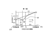
- FIG. 13 is a diagram showing the relationship between the radial distance of the axial fan 100 according to the first embodiment and the size of the outlet angle ⁇ .
- FIG. 13 is a first diagram in which the horizontal axis is the distance in the radial direction of the axial flow fan 100 from the inner peripheral edge portion 24 to the outer peripheral edge portion 23 of the trailing edge portion 22, and the vertical axis is the size of the outlet angle ⁇ .
- FIG. 13 shows the relationship between the magnitude of the outlet angle ⁇ and the radial distance of the trailing edge portion 22 from the inner peripheral edge portion 24 of the axial flow fan 100 as the first diagram L.
- the blade 20 of the axial fan 100 according to the first embodiment will be further described with reference to FIG.
- the position P1 having the size of the outlet angle ⁇ of the trailing edge portion 22 in the inner peripheral edge portion 24 of the axial flow fan 100 and the outlet angle of the trailing edge portion 22 in the outer peripheral edge portion 23 are shown. It is a virtual line represented by a linear straight line connecting the position P2 having the size of ⁇ .
- the position P1 of the size of the exit angle ⁇ of the trailing edge portion 22 in the inner peripheral edge portion 24 is the position of the innermost peripheral portion of the trailing edge portion 22.
- the position P2 of the size of the exit angle ⁇ of the trailing edge portion 22 in the outer peripheral edge portion 23 is the position of the innermost peripheral portion of the trailing edge portion 22. That is, the exit angle ⁇ at the position P1 is the exit angle ⁇ of the innermost peripheral portion of the trailing edge portion 22. Further, the exit angle ⁇ at the position P2 is the exit angle ⁇ of the outermost peripheral portion of the trailing edge portion 22.
- the magnitude of the outlet angle ⁇ increases with a constant magnitude from the inner peripheral edge portion 24 toward the outer peripheral edge portion 23, as in the axial flow fan 100L according to the above-mentioned comparative example. , Represented linearly.
- the first diagram L has a lower convex portion UD that is convex downward from the first virtual diagram VL.
- the lower convex portion UD may have a region D1 formed so that the size of the outlet angle ⁇ decreases toward the outer peripheral edge portion 23 side from the inner peripheral edge portion 24 side.
- the lower convex portion UD may have a minimum portion DN that forms a minimum value of the exit angle ⁇ in the lower convex portion UD.
- the wing 20 having the minimum portion DN is the portion where the exit angle ⁇ is in the middle of the radial distance in relation to the magnitude of the exit angle ⁇ with respect to the radial distance of the trailing edge portion 22 from the inner peripheral edge portion 24.
- the minimum portion DN forms the apex portion 22b1 in the second region 22b.
- the apex portion 22b1 is a portion having the smallest exit angle ⁇ in the second region 22b, and is a portion having the largest wing loading in the second region 22b.
- the lower convex portion UD is formed on the inner peripheral side of the outer peripheral edge portion 23. It is more effective that the lower convex portion UD is formed on the inner peripheral side of the central position CL of the blade 20 in the radial direction of the axial flow fan 100.
- the lower convex portion UD may be formed at the center position CL of the wing 20.
- FIG. 14 is a diagram of another example showing the relationship between the radial distance of the axial fan 100 according to the first embodiment and the size of the outlet angle ⁇ .
- FIG. 14 is a first diagram showing the relationship between the distance in the radial direction and the size of the exit angle ⁇ , as in FIG. 13.
- the lower convex portion UD has a linear portion D2 in which the size of the exit angle ⁇ is formed to be constant from the inner peripheral edge portion 24 side to the outer peripheral edge portion 23 side. May be.
- the blade 20 of the axial flow fan 100 has a first linear portion LI formed linearly between the inner peripheral edge portion 24 and the lower convex portion UD in the first diagram L. Further, the blade 20 of the axial flow fan 100 has a second linear portion LO formed linearly between the outer peripheral edge portion 23 and the lower convex portion UD in the first diagram L.
- the lower convex portion UD may be formed with a gentle inclination with respect to the inclination of the first linear portion LI, and may have a linear portion continuous with the first linear portion LI. That is, the lower convex portion UD may be formed so that the linear portion D2 in FIG. 14 described above has a gentle inclination with respect to the inclination of the first linear portion LI.
- the portion of the trailing edge portion 22 constituting the first linear portion LI of the first diagram L is defined as the first region 22a
- the trailing edge portion 22 constituting the lower convex portion UD of the first diagram L is defined as the first region 22a.
- the portion is referred to as a second region 22b
- the portion constituting the second linear portion LO of the first diagram L is referred to as a second region 22b.
- the trailing edge portion 22 of the axial flow fan 100 has a first region 22a, a second region 22b, and a third region from the inner peripheral side (Y1 side) to the outer peripheral side (Y2 side).
- the regions 22c are formed in this order.
- FIG. 15 is a diagram of the wing cross section WS1 of the A1-A1 line cross section passing through the first region 22a of FIG. 7.
- FIG. 16 is a view of the wing cross section WS3 of the A3-A3 line cross section passing through the third region 22c of FIG. 7.
- the exit angle ⁇ 1 of the first region 22a is smaller than the exit angle ⁇ 3 of the third region 22c, and the exit angle ⁇ 3 of the third region 22c is formed to be larger than the exit angle ⁇ 1 of the first region 22a (exit angle). ⁇ 1 ⁇ exit angle ⁇ 3).
- the blade cross section WS1 of the blade 20 forming the outlet angle ⁇ 1 is in a state where the positive pressure surface 25 of the blade 20 stands up with respect to the rotation direction DR as compared with the blade cross section WS3 of the blade 20 forming the outlet angle ⁇ 3.
- the positive pressure surface 25 has an angle close to a right angle with respect to the rotation direction DR. Therefore, the portion of the blade 20 forming the outlet angle ⁇ 1 has a larger blade load than the portion of the blade 20 forming the outlet angle ⁇ 3.
- the blade cross section WS3 of the blade 20 forming the outlet angle ⁇ 3 is in a state where the positive pressure surface 25 of the blade 20 lies down with respect to the rotation direction DR as compared with the blade cross section WS1 of the blade 20 forming the outlet angle ⁇ 1. That is, the positive pressure surface 25 has an angle close to parallel to the rotation direction DR. Therefore, the portion of the blade 20 forming the outlet angle ⁇ 3 has a smaller wing loading than the portion of the blade 20 forming the exit angle ⁇ 1.
- the axial fan 100 is formed so that the blade load is larger on the inner peripheral side than on the outer peripheral side of the lower convex portion UD from the viewpoint of the outlet angle ⁇ . That is, when viewed from the entire blade 20, the outlet angle ⁇ of the trailing edge portion 22 on the inner peripheral edge portion 24 side of the axial flow fan 100 is smaller than the outlet angle ⁇ of the trailing edge portion 22 on the outer peripheral edge portion 23 side. It is formed like this.
- the axial flow fan 100 is formed so that the outlet angle ⁇ increases from the inner peripheral side to the outer peripheral side in each of the first region 22a and the third region 22c. More specifically, the axial fan 100 is formed in the first region 22a so that the inner peripheral side of the first region 22a has an outlet angle ⁇ S and the outer peripheral side of the first region 22a has an outlet angle ⁇ L. Is formed in.
- the axial flow fan 100 is formed so that the inner peripheral side of the third region 22c has an outlet angle ⁇ S and the outer peripheral side of the third region 22c has an outlet angle ⁇ L.
- the axial flow fan 100 is formed so that the first region 22a located on the inner peripheral side of the axial flow fan 100 has an outlet angle ⁇ S as a whole, and is located on the outer peripheral side of the axial flow fan 100.
- the three regions 22c are formed so as to have an outlet angle ⁇ L.
- FIG. 17 is a diagram of the wing cross section WS2 of the A2-A2 line cross section passing through the second region 22b of FIG. 7.
- the exit angle ⁇ 2 of the second region 22b is smaller than the exit angle ⁇ 3 of the third region 22c, and the exit angle ⁇ 3 of the third region 22c is formed to be larger than the exit angle ⁇ 2 of the second region 22b (exit angle). ⁇ 2 ⁇ exit angle ⁇ 3).
- the blade cross section WS2 of the blade 20 forming the outlet angle ⁇ 2 is in a state where the positive pressure surface 25 of the blade 20 stands up with respect to the rotation direction DR as compared with the blade cross section WS3 of the blade 20 forming the outlet angle ⁇ 3.
- the positive pressure surface 25 has an angle close to a right angle with respect to the rotation direction DR. Therefore, the portion of the blade 20 forming the outlet angle ⁇ 2 has a larger blade load than the portion of the blade 20 forming the outlet angle ⁇ 3.
- the blade cross section WS3 of the blade 20 forming the outlet angle ⁇ 3 is in a state where the positive pressure surface 25 of the blade 20 lies down with respect to the rotation direction DR as compared with the blade cross section WS2 of the blade 20 forming the outlet angle ⁇ 2. That is, the positive pressure surface 25 has an angle close to parallel to the rotation direction DR. Therefore, the portion of the blade 20 forming the outlet angle ⁇ 3 has a smaller wing loading than the portion of the blade 20 forming the exit angle ⁇ 2.
- the exit angle ⁇ 2 of the second region 22b has a portion (exit angle ⁇ 2 ⁇ exit angle ⁇ 1) equal to or smaller than the exit angle ⁇ 1 of the first region 22a.
- the exit angle ⁇ 2 of the second region 22b of the blade 20 is smaller than the exit angle ⁇ 1 of the first region 22a.
- the blade cross section WS2 of the blade 20 forming the outlet angle ⁇ 2 is in a state where the positive pressure surface 25 of the blade 20 stands up with respect to the rotation direction DR, that is, the positive pressure surface, as compared with the blade cross section WS1 of the blade 20 forming the outlet angle ⁇ 1.
- 25 is an angle close to a right angle with respect to the rotation direction DR.
- the portion of the blade 20 in which the outlet angle ⁇ 2 of the second region 22b is smaller than the outlet angle ⁇ 1 of the first region 22a has a larger wing loading than the portion of the blade 20 forming the exit angle ⁇ 1 of the portion. ..
- the exit angle ⁇ 2 of the second region 22b has a portion equal to or smaller than the exit angle ⁇ 1 of the first region 22a (exit angle ⁇ 2 ⁇ exit angle ⁇ 1).
- the positive pressure surface 25 of the blade 20 stands up as compared with the blade 20L forming the first virtual diagram VL, that is, the positive pressure surface 25 is at an angle close to a right angle to the rotation direction DR. Therefore, when the outlet angle ⁇ 2 of the second region 22b has a portion equal to or smaller than the exit angle ⁇ 1 of the first region 22a, that is, when the lower convex portion UD is provided, the wing 20 having the region is provided. Has a larger blade load than the blade 20L forming the first virtual diagram VL.
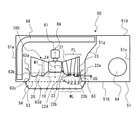
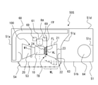
- FIG. 18 is a top view conceptually showing the outdoor unit 50 provided with the axial fan 100 according to the first embodiment.
- the axial flow fan 100 is shown as a shape when rotationally projected onto a meridional surface including a rotation axis RA and a blade 20.
- the outdoor unit 50L is provided on the blade surface by a partition plate 51g or the like that inhibits the suction of air into the axial fan 100L.
- the air flow FL having a radial component from the inner peripheral side to the outer peripheral side increases.
- the blade load of the outdoor unit 50L according to the comparative example cannot be adjusted in the radial direction of the axial fan 100L, and the blade load on the inner peripheral side is sufficiently increased with respect to the outer peripheral side of the axial fan 100L. do not have. Therefore, in the outdoor unit 50L of the comparative example, the air flow concentrated on the outermost circumference or the outer periphery of the axial flow fan 100L collides with a structure such as a fan grill located on the downstream side of the outer peripheral portion of the axial flow fan 100L. , Noise increases.
- the axial fan 100 according to the first embodiment is formed so that the first diagram L has a lower convex portion UD that is convex downward from the first virtual diagram VL.
- Has wings 20 When having the lower convex portion UD, the wing 20 having the region concerned has the exit angle ⁇ of the wing 20 by having the lower convex portion UD as compared with the wing 20L forming the first virtual diagram VL. Has a small portion, so that the wing loading is large in the portion constituting the lower convex portion UD.
- the axial flow fan 100 can attract the air flow on the blade surface to the inner peripheral side by sufficiently increasing the blade load on the inner peripheral side with respect to the outer peripheral side, and is blown out from the axial flow fan 100.
- the air flow becomes a uniform wind speed distribution in the radial direction.
- the outdoor unit 50 can suppress the resistance due to the collision with the fan grill 54 by the uniform wind speed distribution of the air blown from the axial fan 100. Therefore, the outdoor unit 50 can reduce the load on the axial fan 100 and reduce the fan input.
- the lower convex portion UD is formed on the inner peripheral side of the central position CL of the blade 20 in the radial direction of the axial fan 100.
- the air flow on the blade surface is directed to the inner peripheral side even if the air flow on the blade surface is largely biased toward the outer peripheral side.
- the air flow blown out from the axial flow fan 100 can be uniformly distributed in the radial direction.
- the wing 20 has a first linear portion LI formed linearly between the inner peripheral edge portion 24 and the lower convex portion UD in the first diagram L. Further, the wing 20 has a second linear portion LO formed linearly between the outer peripheral edge portion 23 and the lower convex portion UD in the first diagram L. By having the portion, the blade 20 can have a different magnitude of the blade load between the portion constituting the lower convex portion UD and the first linear portion LI or the second linear portion LO.
- the lower convex portion UD is formed with a gentle inclination with respect to the inclination of the first linear portion LI, and has a linear portion D2 continuous with the first linear portion LI. Since the blade 20 having the region has a portion where the exit angle ⁇ of the blade 20 is small due to having the minimum portion DN as compared with the blade 20L forming the first virtual diagram VL, the minimum portion DN The wing loading is particularly large at the apex portion 22b1 of the wing 20 constituting the above.
- the axial flow fan 100 can attract the air flow on the blade surface to the inner peripheral side by sufficiently increasing the blade load on the inner peripheral side with respect to the outer peripheral side, and is blown out from the axial flow fan 100.
- the air flow becomes a uniform wind speed distribution in the radial direction.
- the axial flow fan 100 is mounted on the outdoor unit 50, it is possible to suppress noise when it collides with a structure such as a fan grill located on the downstream side of the axial flow fan 100, and as described above.
- the fan input can be reduced.
- the lower convex portion UD is formed so as to have a minimum portion DN that forms a minimum value of the exit angle ⁇ . Since the blade 20 has a portion where the exit angle ⁇ of the blade 20 is small due to having the minimum portion DN as compared with the blade 20L forming the first virtual diagram VL, the blade 20 constitutes the minimum portion DN.
- the wing loading is particularly large at 20 and the apex 22b1.
- the axial flow fan 100 can attract the air flow on the blade surface to the inner peripheral side by sufficiently increasing the blade load on the inner peripheral side with respect to the outer peripheral side, and is blown out from the axial flow fan 100.
- the air flow becomes a uniform wind speed distribution in the radial direction.
- the axial flow fan 100 is mounted on the outdoor unit 50, it is possible to suppress noise when it collides with a structure such as a fan grill located on the downstream side of the axial flow fan 100, and as described above.
- the fan input can be reduced.
- the outdoor unit 50 of the air conditioner 70 has an axial fan 100, and can exert the effect of the above-mentioned axial fan 100.
- FIG. 19 is a front view showing a schematic configuration of the blade 20 of the axial fan 100 according to the second embodiment.
- FIG. 20 is a sectional view taken along line AA of the wing 20 of FIGS. 7 and 19. Note that FIG. 19 shows only one of the plurality of wings 20 and omits the other wings 20 in order to explain the configuration of the wings 20. Further, the white arrow F shown in FIG. 20 indicates the direction in which the air flows. Parts having the same configuration as the axial fan 100 and the outdoor unit 50 of FIGS. 1 to 18 are designated by the same reference numerals, and the description thereof will be omitted.
- the axial fan 100 according to the second embodiment specifies the configuration of the inlet angle ⁇ of the blade 20 described later.
- the angle between the virtual line LC parallel to the rotation axis RA intersecting the leading edge portion 21 and the virtual line LD indicating the direction in which the leading edge portion 21 is facing is set to the angle of the wing 20. It is defined as the entrance angle ⁇ .
- the inlet angle ⁇ is an angle between the virtual line LC and the virtual line LD in the blade cross section WS of the blade 20, is located on the upstream side of the air flow with respect to the virtual line LD, and is , The angle of the region located on the DR side in the rotation direction with respect to the virtual line LC.
- the entrance angle ⁇ forms an angle of 90 degrees or less.
- FIG. 21 is a sectional view taken along line AA of the wing 20 when the inlet angle ⁇ S is provided.
- FIG. 22 is a sectional view taken along line AA of the blade 20 when the blade 20 has an inlet angle ⁇ L.
- the entrance angle ⁇ S is smaller than the entrance angle ⁇ L, and the entrance angle ⁇ L is larger than the entrance angle ⁇ S (entrance angle ⁇ S ⁇ entrance angle ⁇ L).
- the blade cross section WS of the blade 20 forming the inlet angle ⁇ S is in a state where the positive pressure surface 25 of the blade 20 stands up with respect to the rotation direction DR as compared with the blade cross section WS of the blade 20 forming the inlet angle ⁇ L.
- the positive pressure surface 25 has an angle close to a right angle with respect to the rotation direction DR. Therefore, the portion of the blade 20 forming the inlet angle ⁇ S has a larger wing loading than the portion of the blade 20 forming the inlet angle ⁇ L.
- the blade cross section WS of the blade 20 forming the inlet angle ⁇ L is in a state where the positive pressure surface 25 of the blade 20 lies down with respect to the rotation direction DR as compared with the blade cross section WS of the blade 20 forming the inlet angle ⁇ S. That is, the positive pressure surface 25 has an angle close to parallel to the rotation direction DR. Therefore, the portion of the blade 20 forming the inlet angle ⁇ L has a smaller wing loading than the portion of the blade 20 forming the inlet angle ⁇ S.
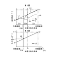
- FIG. 23 is a diagram showing the relationship between the wings 20 in FIGS. 1 and 2.
- FIG. 23 has the above-mentioned first figure as the upper figure, and shows the second figure described later as the lower figure.
- FIG. 2 is a diagram in which the horizontal axis is the distance in the radial direction of the axial flow fan 100 from the inner peripheral edge portion 24 to the outer peripheral edge portion 23 of the leading edge portion 21, and the vertical axis is the size of the inlet angle ⁇ . ..
- FIG. 2 shows the relationship between the magnitude of the inlet angle ⁇ and the radial distance of the leading edge portion 21 from the inner peripheral edge portion 24 of the axial flow fan 100 as the second diagram L2.
- the second diagram L2 shows the position Q1 of the size of the entrance angle ⁇ of the leading edge portion 21 in the inner peripheral edge portion 24 of the axial flow fan 100 and the size of the entrance angle ⁇ of the leading edge portion 21 in the outer peripheral edge portion 23. It is a line represented by a linear straight line connecting the position Q2 and the position Q2.
- the second virtual diagram VL2 is linearly represented so that the size of the entrance angle ⁇ increases with a constant size from the inner peripheral edge portion 24 of the leading edge portion 21 toward the outer peripheral edge portion 23.
- the position Q1 of the size of the entrance angle ⁇ of the leading edge portion 21 in the inner peripheral edge portion 24 is the position of the innermost peripheral portion of the leading edge portion 21.
- the position Q2 of the size of the entrance angle ⁇ of the leading edge portion 21 in the outer peripheral edge portion 23 is the position of the innermost peripheral portion of the leading edge portion 21. That is, the entrance angle ⁇ at the position Q1 is the entrance angle ⁇ of the innermost peripheral portion of the leading edge portion 21. Further, the entrance angle ⁇ at the position Q2 is the entrance angle ⁇ of the outermost peripheral portion of the leading edge portion 21.
- FIG. 1 and FIG. 2 are compared.
- the entrance angle ⁇ 1 of the partial GF of the second diagram L2 located at a distance equal to the radial distance of the minimum portion DN of the exit angle ⁇ in the first diagram L. Is formed to be smaller than the size of the entrance angle ⁇ 2 of the outer peripheral edge portion 23 of the leading edge portion 21.
- the portion of the leading edge portion 21 constituting the partial GF is referred to as a leading edge side load portion 21b.
- FIG. 24 is a top view conceptually showing the outdoor unit 50 provided with the axial fan 100 according to the second embodiment.
- the axial fan 100 is shown as a shape when rotationally projected onto the meridional surface including the rotary axis RA and the blade 20.
- the size of the inlet angle ⁇ in FIG. 2 of the portion GF located at a distance equal to the radial distance of the position of the minimum portion DN of the outlet angle ⁇ in FIG. 1 is the leading edge portion 21. It has a wing 20 formed to be smaller than the size of the entrance angle ⁇ of the outer peripheral edge portion 23. Therefore, the wing 20 is formed so that the wing loading of the leading edge side load portion 21b constituting the partial GF is larger than the wing loading of the outer peripheral edge portion 23 of the leading edge portion 21.
- the axial fan 100 can sufficiently increase the blade load at the radial position where the apex portion 22b1 constituting the minimum portion DN is located with respect to the outer peripheral side on the front edge side of the blade 20. can. Therefore, the axial fan 100 can attract the air flow to the second region 22b having the minimum DN of the trailing edge portion 22 as compared with the axial fan 100 according to the first embodiment, and the axial fan 100 can attract the air flow from the axial fan 100.
- the flow of the blown air has a uniform wind speed distribution WL in the radial direction.
- the minimum portion DN is a portion that constitutes the minimum value of the exit angle ⁇ at the trailing edge portion 22 of the blade 20.
- the outdoor unit 50 of the air conditioner 70 according to the second embodiment has an axial fan 100, and can exert the effect of the above-mentioned axial fan 100.
- FIG. 25 is a top view conceptually showing the outdoor unit 50 provided with the axial fan 100 according to the third embodiment.
- the axial flow fan 100 is shown as a shape when rotationally projected onto the meridional surface including the rotary axis RA and the blade 20. Parts having the same configuration as the axial fan 100 and the outdoor unit 50 of FIGS. 1 to 24 are designated by the same reference numerals, and the description thereof will be omitted.
- the axial fan 100 according to the third embodiment specifies the position of the front edge side load portion 21b constituting the partial GF.
- the axial fan 100 according to the third embodiment will be described with reference to FIGS. 19 to 25.
- the direction from the leading edge portion 21 to the trailing edge portion 22 along the axial direction of the rotation axis RA is defined as the direction in which air flows.
- the white arrow F shown in FIG. 25 indicates the direction in which air flows.
- the portion 21 is defined as the leading edge side load portion 21b.
- the outer peripheral edge portion 23 of the leading edge portion 21 is defined as the leading edge outer peripheral portion 21c.
- the leading edge side load portion 21b is formed on the downstream side of the leading edge outer peripheral portion 21c in the direction of air flow.
- the axial flow fan 100 can attract the air flow to the second region 22b having the minimum portion DN of the trailing edge portion 22 as compared with the axial flow fan 100 according to the first embodiment, and the axial flow fan 100 can be attracted.
- the air flow blown out from the air flow has a uniform wind speed distribution WL in the radial direction.
- the outdoor unit 50 of the air conditioner 70 according to the third embodiment has an axial fan 100, and can exert the effect of the above-mentioned axial fan 100.
- FIG. 26 is a diagram showing the relationship between the blades 20 in FIGS. 1 and 2 of the axial fan 100 according to the fourth embodiment.
- FIG. 26 has the above-mentioned first figure as the upper figure, and shows the second figure of the axial flow fan 100 according to the fourth embodiment described later as the lower figure.
- FIG. 2 is a diagram in which the horizontal axis is the distance in the radial direction of the axial flow fan 100 from the inner peripheral edge portion 24 to the outer peripheral edge portion 23 of the leading edge portion 21, and the vertical axis is the size of the inlet angle ⁇ . ..
- FIG. 2 of FIG. 26 shows the relationship between the magnitude of the inlet angle ⁇ and the radial distance of the leading edge portion 21 from the inner peripheral edge portion 24 of the axial flow fan 100 as the second diagram L2.
- the position Q1 of the size of the inlet angle ⁇ of the leading edge portion 21 in the inner peripheral edge portion 24 of the axial flow fan 100 and the leading edge portion in the outer peripheral edge portion 23 is a virtual line represented by a linear straight line connecting the position Q2 with the size of the entrance angle ⁇ of 21.
- the second virtual diagram VL2 is linearly represented so that the size of the entrance angle ⁇ increases with a constant size from the inner peripheral edge portion 24 of the leading edge portion 21 toward the outer peripheral edge portion 23.
- FIG. 26 FIG. 1 and FIG. 2 are compared.
- the entrance angle ⁇ 1 of the partial GF of the second diagram L2 located at a distance equal to the radial distance of the minimum portion DN of the exit angle ⁇ in the first diagram L. Is formed to be smaller than the size of the entrance angle ⁇ 2 of the outer peripheral edge portion 23 of the leading edge portion 21.
- the second diagram L2 has at least one upper convex portion UM that is convex upward from the second virtual diagram VL2.
- the upper convex portion UM may have a maximum portion MA that forms a maximum value of the entrance angle ⁇ in the upper convex portion UM.
- the maximum portion MA forms a leading edge apex portion 22 m on the leading edge portion 21.
- the leading edge apex portion 22m is the apex portion of the portion where the positive pressure surface 25 protrudes in the rotation direction RD.
- the wing 20 of the portion constituting the leading edge apex portion 22 m may be curved, or the wing 20 may be formed to be thicker.
- the convex portion 21r of the leading edge portion 21 constituting the upper convex portion UM is located on the outer peripheral side of the wing 20 in the radial direction with respect to the radial position of the apex portion 22b1 of the trailing edge portion 22 constituting the minimum portion DN. It is formed. That is, the convex portion 21r of the leading edge portion 21 constituting the upper convex portion UM is formed on the outer peripheral side of the position in the radial direction of the leading edge side load portion 21b constituting the partial GF of the second diagram L2. There is. In FIGS. 26 and 19, the leading edge apex portion 22m is formed at the center position CL of the wing 20, but the leading edge apex portion 22m may not be formed at the center position CL of the wing 20. ..
- the blade 20 of the axial flow fan 100 has a third linear portion LI1 formed linearly between the inner peripheral edge portion 24 of the leading edge portion 21 and the upper convex portion UM in the second diagram L2.
- the upper convex portion UM is formed to have a steep inclination with respect to the inclination of the third linear portion LI1.
- the blade 20 of the axial flow fan 100 has a fourth linear portion LO2 formed linearly between the outer peripheral edge portion 23 of the leading edge portion 21 and the upper convex portion UM in the second diagram L2. ..
- the portion of the leading edge portion 21 constituting the third linear portion LI1 of the second diagram L2 is defined as the region 21q
- the portion of the leading edge portion 21 constituting the upper convex portion UM of the second diagram L2 is convex.
- the shape portion 21r is defined
- the portion constituting the fourth linear portion LO2 in the second diagram L2 is defined as the region 21s.
- the leading edge portion 21 of the axial flow fan 100 has a region 21q, a convex portion 21r, and a region 21s in this order from the inner peripheral side (Y1 side) to the outer peripheral side (Y2 side). It is formed.
- the entrance angle ⁇ of the region 21q is smaller than the entrance angle ⁇ of the region 21s, and the entrance angle ⁇ of the region 21s is formed larger than the entrance angle ⁇ of the region 21q. Therefore, the axial fan 100 is formed so that the blade load is larger on the inner peripheral side than on the outer peripheral side of the upper convex portion UM from the viewpoint of the inlet angle ⁇ .
- the axial flow fan 100 is formed so that the inlet angle ⁇ increases from the inner peripheral side to the outer peripheral side in each of the region 21q and the region 21s.
- the convex portion 21r of the leading edge portion 21 constituting the upper convex portion UM is located on the outer peripheral side of the wing 20 in the radial direction with respect to the radial position of the apex portion 22b1 of the trailing edge portion 22 constituting the minimum portion DN. It is formed.
- the axial flow fan 100 can greatly change the radial blade load on the front edge side, and attracts the air flow to the radial position having the second region 22b of the trailing edge portion 22. can.
- the axial flow fan 100 can attract the air flow to the second region 22b having the minimum portion DN of the trailing edge portion 22 as compared with the axial flow fan 100 according to the first embodiment, and the axial flow fan 100 can be attracted.
- the air flow blown out from the air flow has a uniform wind speed distribution WL in the radial direction.
- the upper convex portion UM is formed so as to have a maximum portion MA forming a maximum value.
- the axial flow fan 100 can further significantly change the radial blade load on the front edge side, and causes the air flow to the radial position having the second region 22b of the trailing edge portion 22. Can be attracted.
- the axial flow fan 100 can attract the air flow to the second region 22b having the minimum portion DN of the trailing edge portion 22 as compared with the axial flow fan 100 according to the first embodiment, and the axial flow fan 100 can be attracted.
- the air flow blown out from the air flow has a uniform wind speed distribution WL in the radial direction.
- the outdoor unit 50 of the air conditioner 70 according to the fourth embodiment has an axial fan 100, and can exert the effect of the above-mentioned axial fan 100.
- FIG. 27 is a diagram showing the relationship between the radial distance of the axial fan 100 according to the fifth embodiment and the size of the outlet angle ⁇ .
- FIG. 1 is a diagram in which the horizontal axis is the distance in the radial direction of the axial flow fan 100 from the inner peripheral edge portion 24 to the outer peripheral edge portion 23 of the trailing edge portion 22, and the vertical axis is the size of the outlet angle ⁇ . ..
- the axial fan 100 of the fifth embodiment specifies the position of the minimum portion DN of the axial fan 100 according to the first embodiment shown in FIG.
- the parts having the same configuration as the axial fan 100 and the outdoor unit 50 in FIGS. 1 to 26 are designated by the same reference numerals, and the description thereof will be omitted.
- the outlet angle ⁇ n of the minimum portion DN forming the minimum value of the outlet angle ⁇ is the inner peripheral edge portion of the trailing edge portion 22. It is formed to be smaller than the exit angle ⁇ 1 of 24 (exit angle ⁇ n ⁇ exit angle ⁇ 1). That is, the axial fan 100 is formed so that the size of the outlet angle ⁇ n of the apex portion 22b1 of the trailing edge portion 22 is smaller than the outlet angle ⁇ 1 of the trailing edge inner peripheral portion 22d which is the inner peripheral edge portion 24 of the trailing edge portion 22. Has been done.
- FIG. 28 is a top view conceptually showing an outdoor unit 50R provided with an axial fan 100R according to a comparative example.
- FIG. 29 is a top view conceptually showing the outdoor unit 50 provided with the axial fan 100 according to the fifth embodiment.
- the axial fan 100 and the axial fan 100R are shown as shapes when rotationally projected onto the meridional surface including the rotary axis RA and the blade 20.
- the outlet angle ⁇ n of the minimum portion DN is formed to be smaller than the outlet angle ⁇ 1 of the inner peripheral edge portion 24 of the trailing edge portion 22.
- the exit angle ⁇ 1 is the exit angle of the innermost peripheral portion of the trailing edge portion 22. That is, the axial flow fan 100 has a minimum portion DN forming an outlet angle ⁇ smaller than the innermost peripheral portion of the fan on the outer peripheral side in the radial direction from the innermost peripheral portion of the fan.
- the axial flow fan 100 When the axial flow fan 100 attracts an air flow from the outer peripheral side of the fan to the apex portion 22b1 constituting the minimum portion DN, the axial flow fan 100 has such a configuration, so that the inner circumference of the axial flow fan 100 is larger than that of the apex portion 22b1 constituting the minimum portion DN. It is possible to suppress the attraction of air to the hub 10 located on the side. Therefore, as shown in FIG. 29, the axial flow fan 100 can suppress the air turbulence TB when the air flow around the hub 10 is separated from the downstream side of the hub 10 and is generated. As a result, the outdoor unit 50 can suppress the generation of noise due to the air turbulence TB, and can suppress the increase in the fan input due to the air turbulence TB.
- the axial flow fan 100 can attract an air flow to the apex portion 22b1 constituting the minimum portion DN of the trailing edge portion 22, and the axial flow fan 100 can be used from the axial flow fan 100.
- the flow of the blown air has a uniform wind speed distribution WL in the radial direction.
- the outdoor unit 50 of the air conditioner 70 according to the fifth embodiment has an axial fan 100, and can exert the effect of the above-mentioned axial fan 100.
- FIG. 30 is a top view conceptually showing the outdoor unit 50 according to the sixth embodiment.
- the axial fan 100 is shown as a shape when rotationally projected onto the meridional surface including the rotary axis RA and the blade 20.
- the parts having the same configuration as the axial fan 100 and the outdoor unit 50 in FIGS. 1 to 29 are designated by the same reference numerals and the description thereof will be omitted.
- the outdoor unit 50 of the sixth embodiment specifies the relationship between the axial fan 100 and the bell mouth 63.
- the arrow FS shown in FIG. 30 shows an example of the flow of air sucked into the bell mouth 63.
- the outdoor unit 50 includes a housing 51 in which an air outlet 53 is formed on a front wall portion 51b, an axial fan 100 according to the first to fifth embodiments arranged inside the housing 51, and an outlet. It has a bell mouth 63 provided in 53 and surrounds the outer periphery of the axial flow fan 100.
- the bell mouth 63 is formed so as to extend in the axial direction of the rotation axis RA.
- the bell mouth 63 has a suction portion from the upstream side to the downstream side in the first direction W1 in which the air flow generated by the axial flow fan 100 is directed from the inside to the outside of the housing 51 through the opening 63d of the bell mouth 63. It has a 63a, a straight pipe portion 63b, and a blowout portion 63c.
- the suction portion 63a is formed so that the opening diameter on the upstream side of the air flow is larger than the opening diameter on the downstream side in the first direction W1.
- the straight pipe portion 63b is formed in a straight tubular shape having a constant opening diameter in the first direction W1.
- the blowout portion 63c is formed so that the opening diameter on the downstream side of the air flow is larger than the opening diameter on the upstream side in the first direction W1.
- the outdoor unit 50 is arranged at a position where the second region 22b, which is a portion of the trailing edge portion 22 forming the lower convex portion UD, is covered with the straight pipe portion 63b in the axial direction of the rotation axis RA. That is, the second region 22b of the axial flow fan 100 is arranged in the opening formed by the straight pipe portion 63b. The second region 22b of the axial flow fan 100 is arranged between the rotary shaft RA and the straight pipe portion 63b of the bell mouth 63.
- the straight tube portion 63b of the bell mouth 63 is where the opening 63d is most narrowed down in the bell mouth 63. Therefore, the air flow sucked by the drive of the axial flow fan 100 is most concentrated in the straight pipe portion 63b in the bell mouth 63.
- the outdoor unit 50 according to the sixth embodiment is arranged at a position where the second region 22b, which is a portion of the trailing edge portion 22 forming the lower convex portion UD, is covered with the straight pipe portion 63b where the air flow is concentrated. Has been done. Therefore, the outdoor unit 50 according to the sixth embodiment has a wing loading on the inner peripheral side of the axial fan 100 as compared with an outdoor unit in which the second region 22b is not arranged at a position covered by the straight pipe portion 63b. It can be further increased.
- the outdoor unit 50 according to the sixth embodiment includes the axial fan 100 according to the first to fifth embodiments. Therefore, the outdoor unit 50 according to the sixth embodiment can exert the effect of the above-mentioned axial fan 100.
- FIG. 31 is a top view conceptually showing the outdoor unit 50 according to the seventh embodiment.
- the axial flow fan 100 is shown as a shape when rotationally projected onto the meridional surface including the rotation axis RA and the blade 20.
- the parts having the same configuration as the axial fan 100 and the outdoor unit 50 in FIGS. 1 to 30 are designated by the same reference numerals, and the description thereof will be omitted.
- the outdoor unit 50 of the seventh embodiment specifies the shape of the blade 20 of the axial fan 100.
- the second region 22b which is a portion of the trailing edge portion 22 forming the lower convex portion UD, is directed toward the downstream side through which air flows in the axial direction of the rotation shaft RA. It is formed in a convex shape so as to protrude.
- the apex portion 22b1 is formed in a convex shape so as to form the apex of the mountain in the axial direction.
- the second region 22b may be formed in a substantially triangular shape.
- the second region 22b formed in a convex shape is not limited to the shape formed in a substantially triangular shape, and may be projected so as to form an arcuate edge, for example, in a substantially polygonal shape. It may be formed.
- the outdoor unit 50 according to the seventh embodiment can blow out the air flow blown out from the axial fan 100 so as to have a uniform wind speed distribution WL in the radial direction.
- the outdoor unit 50 can suppress noise when colliding with a structure such as a fan grill located on the downstream side of the axial flow fan 100, and as described above, the fan input of the axial flow fan 100 is reduced. can.
- FIG. 32 is a top view conceptually showing the outdoor unit 50 according to the eighth embodiment.
- the axial flow fan 100 is shown as a shape when rotationally projected onto a meridional surface including a rotation axis RA and a blade 20.
- the parts having the same configuration as the axial fan 100 and the outdoor unit 50 in FIGS. 1 to 31 are designated by the same reference numerals, and the description thereof will be omitted.
- the outdoor unit 50 of the eighth embodiment specifies the shape of the blade 20 of the axial fan 100.
- the trailing edge portion 22 of the axial flow fan 100 is located on the outer peripheral side of the second region 22b, which is a portion forming the lower convex portion UD, from the second region 22b, which is a portion forming the lower convex portion, to the outer peripheral edge. It is formed so as to be located on the upstream side of the air flow toward the portion 23.
- the outer peripheral edge portion 23 of the trailing edge portion 22 is defined as the trailing edge outer peripheral portion 22e.
- the trailing edge outer peripheral portion 22e is the outermost peripheral portion of the trailing edge portion 22. As shown in FIG. 32, the trailing edge outer peripheral portion 22e is formed on the upstream side of the second region 22b in the direction of air flow.
- the trailing edge outer peripheral portion 22e is formed on the upstream side of the apex portion 22b1 in the direction of air flow.
- FIG. 33 is a top view conceptually showing a modified example of the outdoor unit 50 according to the eighth embodiment.
- the axial flow fan 100 is shown as a shape when rotationally projected onto the meridional surface including the rotation axis RA and the blade 20.
- the trailing edge portion 22 of the outdoor unit 50 may have a plurality of second regions 22b.
- the air flows from the second region 22b toward the outer peripheral edge portion 23 on the outer peripheral side of the second region 22b provided on the outermost circumference. It is formed so as to be located on the upstream side of the flow.
- the trailing edge outer peripheral portion 22e is provided on the outermost outer peripheral region 22b in the direction of air flow. It is formed on the upstream side of.
- the trailing edge portion 22 of the axial flow fan 100 is located on the outer peripheral side of the second region 22b, which is a portion forming the lower convex portion UD, from the second region 22b, which is a portion forming the lower convex portion, to the outer peripheral edge. It is formed so as to be located on the upstream side of the air flow toward the portion 23.
- the outdoor unit 50 is a portion where the wing loading on the outer peripheral side is relatively reduced by reducing the region arranged on the straight pipe portion 63b on the outer peripheral side of the axial flow fan 100, and a lower convex portion UD is formed. The wing loading of the second region 22b is increased.
- the axial fan 100 can further attract the air flow to the second region 22b forming the lower convex portion UD, and the outdoor unit 50 according to the eighth embodiment is the air blown from the axial fan 100. Can be blown out so that the flow of air becomes a uniform wind speed distribution WL in the radial direction.
- the outdoor unit 50 can suppress noise when colliding with a structure such as a fan grill located on the downstream side of the axial flow fan 100, and as described above, the fan input of the axial flow fan 100 is reduced. can.
- FIG. 34 is a top view conceptually showing the outdoor unit 50 according to the ninth embodiment.
- the axial flow fan 100 is shown as a shape when rotationally projected onto the meridional surface including the rotation axis RA and the blade 20.
- the parts having the same configuration as the axial fan 100 and the outdoor unit 50 in FIGS. 1 to 33 are designated by the same reference numerals, and the description thereof will be omitted.
- the outdoor unit 50 of the ninth embodiment specifies the relationship between the axial fan 100 and the bell mouth 63.
- the trailing edge portion 22 of the portion connected to the hub 10 is located upstream of the straight pipe portion 63b in the air flow direction, and in the axial direction of the rotary shaft RA, It is configured to be arranged at a position not covered by the straight pipe portion 63b.
- the inner peripheral edge portion 24 of the trailing edge portion 22 is defined as the trailing edge inner peripheral portion 22d.
- the trailing edge inner peripheral portion 22d is the innermost peripheral portion of the trailing edge portion 22, and is the trailing edge portion 22 of the portion connected to the hub 10. Therefore, the trailing edge inner peripheral portion 22d is located on the upstream side of the straight pipe portion 63b in the direction of air flow, and is arranged at a position not covered by the straight pipe portion 63b in the axial direction of the rotation axis RA. There is. That is, in the trailing edge inner peripheral portion 22d, the second region 22b of the axial flow fan 100 is not arranged in the opening formed by the straight pipe portion 63b.
- FIG. 35 is a top view conceptually showing a modified example of the outdoor unit 50 according to the ninth embodiment.
- the axial flow fan 100 is shown as a shape when rotationally projected onto a meridional surface including a rotation axis RA and a blade 20.
- the trailing edge portion 22 of the outdoor unit 50 may have a plurality of second regions 22b.
- the trailing edge portion 22 of the portion connected to the hub 10 is located upstream of the straight pipe portion 63b in the direction of air flow, and the rotary shaft RA It is configured to be arranged at a position not covered by the straight pipe portion 63b in the axial direction of the above.
- the outdoor unit 50 is a portion where the trailing edge portion 22 on the innermost circumference is not covered by the straight pipe portion 63b, so that the wing loading on the innermost circumference is relatively reduced and the lower convex portion UD is formed.
- the wing loading of a second region 22b can be increased.
- the axial fan 100 has such a configuration as that of the second region 22b when the air flow is attracted from the outer peripheral side of the axial fan 100 to the second region 22b forming the lower convex portion UD. It is possible to suppress the attraction of air to the hub 10 located on the inner peripheral side. Therefore, the axial flow fan 100 can suppress the air turbulence TB when the air flow around the hub 10 is separated from the downstream side of the hub 10. As a result, the outdoor unit 50 can suppress the generation of noise due to the air turbulence TB, and can suppress the increase in the fan input due to the air turbulence TB.
- FIG. 36 is a top view conceptually showing the outdoor unit 50 according to the tenth embodiment.
- the axial flow fan 100 is shown as a shape when rotationally projected onto a meridional surface including a rotation axis RA and a blade 20.
- the parts having the same configuration as the axial fan 100 and the outdoor unit 50 in FIGS. 1 to 35 are designated by the same reference numerals, and the description thereof will be omitted.
- the outdoor unit 50 of the tenth embodiment specifies the relationship between the axial fan 100 and the motor support 69.
- the motor 61 is attached to the motor support 69.
- the motor support 69 supports the motor 61 that rotates the hub 10.
- the motor support 69 is formed so as to extend in the vertical direction of the outdoor unit 50.
- the motor support 69 is formed, for example, in a plate shape or in a columnar shape.
- the motor support 69 is formed so that at least a part of the motor support 69 is located outside the motor 61 in the radial direction about the rotation axis RA. Further, the motor support 69 is formed so that at least a part thereof faces the blade 20 of the axial flow fan 100 in the axial direction of the rotary shaft RA.
- the motor support 69 is located on the upstream side of the blade 20 and the blade 20 is located on the downstream side of the motor support 69 in the direction in which the air flowing through the housing 51 by the axial flow fan 100 flows.
- FIG. 37 is a top view conceptually showing the outdoor unit 50S according to the comparative example.
- the axial flow fan 100 is shown as a shape when rotationally projected onto the meridional surface including the rotation axis RA and the blade 20.
- the air inflow FP is hindered by the motor support 69. Therefore, in the outdoor unit 50S, the air flow FL blown out from the axial fan 100 includes a large air turbulence TB.
- the second region 22b which is a portion of the trailing edge portion 22 forming the lower convex portion UD, is axially aligned with the motor support 69. It is formed at opposite positions.
- the second region 22b which is a portion of the trailing edge portion 22 forming the lower convex portion UD, is formed at a position facing the motor support 69 in the axial direction. Since the second region 22b faces the motor support 69, the outdoor unit 50 can allow the air flow to flow into the radial range AL of the blade 20 located downstream of the motor support 69, and the air is turbulent. TB can be suppressed. As a result, the outdoor unit 50 can suppress the generation of noise due to the air turbulence TB, and can suppress the increase in the fan input due to the air turbulence TB.
- FIG. 38 is a front view conceptually showing the outdoor unit 50 according to the eleventh embodiment.
- FIG. 39 is a top view conceptually showing the outdoor unit 50 according to the eleventh embodiment.
- the axial fan 100 is shown as a shape when rotationally projected onto the meridional surface including the rotary axis RA and the blade 20.
- FIG. 38 describes a part of the fan grill 54 and omits the other part of the fan grill 54 in order to explain the relationship between the blade 20 of the axial fan 100 and the crosspiece 54a of the fan grill 54.
- the parts having the same configuration as the axial fan 100 and the outdoor unit 50 of FIGS. 1 to 37 are designated by the same reference numerals, and the description thereof will be omitted.
- the outdoor unit 50 of the eleventh embodiment specifies the relationship between the axial fan 100 and the fan grill 54.
- the outdoor unit 50 has a fan grill 54 arranged at the outlet 53 in order to prevent human fingers from being inserted into the housing 51.
- the fan grill 54 has a plurality of crosspieces 54a extending in the horizontal direction in the vertical direction, and is arranged on the downstream side of the axial flow fan 100 in the direction of air flow.
- the outdoor unit 50 is located on the outer peripheral side of the second region 22b. It has a leading region 22g that passes through the crosspiece 54a of the fan grill 54 before the second region 22b. As described above, the second region 22b is a portion that forms the lower convex portion UD at the trailing edge portion 22.
- the wing 20 rotates, and when the trailing edge portion 22 passes through the crosspiece 54a of the fan grill 54, the trailing edge outer peripheral portion which is the outermost peripheral portion of the trailing edge portion 22.
- the 22e is configured to pass through the crosspiece 54a of the fan grill 54 before the second region 22b.
- FIG. 40 is a front view conceptually showing a modified example of the outdoor unit 50 according to the eleventh embodiment.
- the second region 22b which is a portion of the trailing edge portion 22 forming the lower convex portion UD, projects in the direction opposite to the rotation direction DR of the blade 20. It may be formed in a convex shape as described above.
- the air flow FD around the wing causes the trailing edge portion 22 passing through the rail 54a of the fan grill 54 due to the large resistance generated in the trailing edge portion 22 passing through the rail 54a of the fan grill 54. It will flow into the radial region other than 22.
- the outdoor unit 50 has a leading region 22g on the outer peripheral side of the second region 22b that passes through the crosspiece 54a of the fan grill 54 before the second region 22b, so that the second region 22b is driven by the axial flow fan 100.
- the outer peripheral side of the fan receives air resistance before the second region 22b. Therefore, in the outdoor unit 50, air flows into the second region 22b, and the air flow blown out from the axial fan 100 has a uniform wind speed distribution in the radial direction.
- the outdoor unit 50 can suppress noise when colliding with a structure such as a fan grill located on the downstream side of the axial flow fan 100, and can reduce the fan input as described above.
- the outdoor unit 50 has a convex shape so that the second region 22b, which is a portion of the trailing edge portion 22 forming the lower convex portion UD, protrudes in the direction opposite to the rotation direction DR of the blade 20. It is formed.
- the axial fan 100 can exhibit the viscosity of the blade surface and attract the air flow to the second region 22b forming the lower convex portion UD of the trailing edge portion 22. Therefore, the outdoor unit 50 can blow out the air flow blown out from the axial flow fan 100 so that the wind speed distribution WL becomes uniform in the radial direction.
- the outdoor unit 50 can suppress noise when colliding with a structure such as a fan grill located on the downstream side of the axial flow fan 100, and can reduce the fan input of the axial flow fan 100.
- FIG. 41 is a diagram showing the relationship between the radial distance of the axial fan 100 according to the twelfth embodiment and the size of the outlet angle ⁇ .
- the parts having the same configuration as the axial fan 100 and the outdoor unit 50 in FIGS. 1 to 40 are designated by the same reference numerals, and the description thereof will be omitted.
- the position P1 having the size of the exit angle ⁇ of the trailing edge portion 22 in the inner peripheral edge portion 24 of the axial flow fan 100 and the exit angle of the trailing edge portion 22 in the outer peripheral edge portion 23 are shown. It is a virtual line represented by a linear straight line connecting the position P2 having the size of ⁇ .
- the third virtual diagram VL3 is linearly represented so that the size of the exit angle ⁇ decreases with a constant size from the inner peripheral edge portion 24 toward the outer peripheral edge portion 23.
- the axial flow fan 100 of the first embodiment is formed so that the blade load is larger on the inner peripheral side than on the outer peripheral side of the lower convex portion UD from the viewpoint of the outlet angle ⁇ .
- the axial fan 100 of the twelfth embodiment is formed so that the blade load is larger on the outer peripheral side than on the inner peripheral side of the lower convex portion UD from the viewpoint of the outlet angle ⁇ .
- the outlet angle ⁇ of the trailing edge portion 22 on the outer peripheral edge portion 23 side is the outlet angle of the trailing edge portion 22 on the inner peripheral edge portion 24 side. It is formed so as to be smaller than ⁇ .
- the axial fan 100 may be formed by a blade 20 having an outlet angle ⁇ as shown in the twelfth embodiment.
- the axial fan 100 has a blade 20 forming a first diagram L as shown in FIG. 41 in FIG. As shown in FIG. 41, the first diagram L has a lower convex portion UD that is convex downward from the third virtual diagram VL3.
- the axial fan 100 has a blade 20 that forms a lower convex portion, so that the blade load on the inner peripheral side is sufficiently increased with respect to the outer peripheral side, so that the air flow on the blade surface is inside. Can be attracted to the peripheral side. Therefore, in the axial flow fan 100, the flow of air blown from the axial flow fan 100 has a uniform wind speed distribution in the radial direction. As a result, the axial flow fan 100 and the outdoor unit 50 can suppress noise when colliding with a structure such as a fan grill located on the downstream side of the axial flow fan 100, and can reduce fan input.
- the configuration shown in the above embodiments is an example, and it is also possible to combine the embodiments. Further, the configuration shown in the above embodiments can be combined with another known technique, or a part of the configuration can be omitted or changed without departing from the gist.
Landscapes
- Engineering & Computer Science (AREA)
- Mechanical Engineering (AREA)
- General Engineering & Computer Science (AREA)
- Chemical & Material Sciences (AREA)
- Combustion & Propulsion (AREA)
- Structures Of Non-Positive Displacement Pumps (AREA)
Priority Applications (5)
| Application Number | Priority Date | Filing Date | Title |
|---|---|---|---|
| US18/002,677 US11873833B2 (en) | 2020-09-02 | 2020-09-02 | Axial-flow fan, and outdoor unit for air-conditioning apparatus |
| PCT/JP2020/033229 WO2022049665A1 (ja) | 2020-09-02 | 2020-09-02 | 軸流ファン、及び、空気調和機の室外機 |
| CN202080103353.8A CN115885112A (zh) | 2020-09-02 | 2020-09-02 | 轴流风扇和空调机的室外机 |
| JP2022546773A JP7387012B2 (ja) | 2020-09-02 | 2020-09-02 | 軸流ファン、及び、空気調和機の室外機 |
| EP20952405.7A EP4209682A4 (en) | 2020-09-02 | 2020-09-02 | AXIAL FAN AND INDOOR UNIT FOR AIR CONDITIONING |
Applications Claiming Priority (1)
| Application Number | Priority Date | Filing Date | Title |
|---|---|---|---|
| PCT/JP2020/033229 WO2022049665A1 (ja) | 2020-09-02 | 2020-09-02 | 軸流ファン、及び、空気調和機の室外機 |
Publications (1)
| Publication Number | Publication Date |
|---|---|
| WO2022049665A1 true WO2022049665A1 (ja) | 2022-03-10 |
Family
ID=80490802
Family Applications (1)
| Application Number | Title | Priority Date | Filing Date |
|---|---|---|---|
| PCT/JP2020/033229 Ceased WO2022049665A1 (ja) | 2020-09-02 | 2020-09-02 | 軸流ファン、及び、空気調和機の室外機 |
Country Status (5)
| Country | Link |
|---|---|
| US (1) | US11873833B2 (https=) |
| EP (1) | EP4209682A4 (https=) |
| JP (1) | JP7387012B2 (https=) |
| CN (1) | CN115885112A (https=) |
| WO (1) | WO2022049665A1 (https=) |
Families Citing this family (2)
| Publication number | Priority date | Publication date | Assignee | Title |
|---|---|---|---|---|
| CN117212912A (zh) * | 2023-09-25 | 2023-12-12 | 合肥美的暖通设备有限公司 | 空调室外机及空调器 |
| WO2025107434A1 (zh) * | 2023-11-20 | 2025-05-30 | 青岛海信日立空调系统有限公司 | 空调器 |
Citations (5)
| Publication number | Priority date | Publication date | Assignee | Title |
|---|---|---|---|---|
| JPH09144697A (ja) | 1995-11-21 | 1997-06-03 | Kurita Denki Seisakusho:Kk | 軸流ファン |
| JP2001227498A (ja) * | 2000-02-14 | 2001-08-24 | Hitachi Ltd | プロペラファン |
| JP2008111383A (ja) * | 2006-10-31 | 2008-05-15 | Japan Servo Co Ltd | 軸流ファン |
| JP2014058902A (ja) * | 2012-09-18 | 2014-04-03 | Daikin Ind Ltd | プロペラファン |
| JP2014080970A (ja) * | 2012-09-28 | 2014-05-08 | Daikin Ind Ltd | プロペラファン及びこれを備える空気調和機 |
Family Cites Families (6)
| Publication number | Priority date | Publication date | Assignee | Title |
|---|---|---|---|---|
| JP3528285B2 (ja) | 1994-12-14 | 2004-05-17 | 株式会社日立製作所 | 軸流送風機 |
| ITBO20040417A1 (it) * | 2004-07-06 | 2004-10-06 | Spal Srl | Ventola a flusso assiale |
| JP2007113474A (ja) | 2005-10-20 | 2007-05-10 | Mitsubishi Electric Corp | 送風機 |
| WO2017077564A1 (ja) * | 2015-11-02 | 2017-05-11 | 三菱電機株式会社 | 軸流ファン、及び、その軸流ファンを有する空気調和装置 |
| CN106151105B (zh) * | 2016-08-03 | 2018-07-06 | 华中科技大学 | 一种轴流叶型 |
| JP6373439B1 (ja) * | 2017-03-31 | 2018-08-15 | テラル株式会社 | 軸流ファン |
-
2020
- 2020-09-02 US US18/002,677 patent/US11873833B2/en active Active
- 2020-09-02 WO PCT/JP2020/033229 patent/WO2022049665A1/ja not_active Ceased
- 2020-09-02 CN CN202080103353.8A patent/CN115885112A/zh not_active Withdrawn
- 2020-09-02 EP EP20952405.7A patent/EP4209682A4/en not_active Withdrawn
- 2020-09-02 JP JP2022546773A patent/JP7387012B2/ja active Active
Patent Citations (5)
| Publication number | Priority date | Publication date | Assignee | Title |
|---|---|---|---|---|
| JPH09144697A (ja) | 1995-11-21 | 1997-06-03 | Kurita Denki Seisakusho:Kk | 軸流ファン |
| JP2001227498A (ja) * | 2000-02-14 | 2001-08-24 | Hitachi Ltd | プロペラファン |
| JP2008111383A (ja) * | 2006-10-31 | 2008-05-15 | Japan Servo Co Ltd | 軸流ファン |
| JP2014058902A (ja) * | 2012-09-18 | 2014-04-03 | Daikin Ind Ltd | プロペラファン |
| JP2014080970A (ja) * | 2012-09-28 | 2014-05-08 | Daikin Ind Ltd | プロペラファン及びこれを備える空気調和機 |
Non-Patent Citations (1)
| Title |
|---|
| See also references of EP4209682A4 |
Also Published As
| Publication number | Publication date |
|---|---|
| JPWO2022049665A1 (https=) | 2022-03-10 |
| EP4209682A1 (en) | 2023-07-12 |
| CN115885112A (zh) | 2023-03-31 |
| US11873833B2 (en) | 2024-01-16 |
| JP7387012B2 (ja) | 2023-11-27 |
| EP4209682A4 (en) | 2023-10-18 |
| US20230235750A1 (en) | 2023-07-27 |
Similar Documents
| Publication | Publication Date | Title |
|---|---|---|
| JP6811866B2 (ja) | プロペラファン、送風装置、及び冷凍サイクル装置 | |
| JP7387012B2 (ja) | 軸流ファン、及び、空気調和機の室外機 | |
| JP7130136B2 (ja) | 軸流ファン、送風装置、及び、冷凍サイクル装置 | |
| JP7378611B2 (ja) | 軸流ファン、送風装置、及び、冷凍サイクル装置 | |
| JP7258136B2 (ja) | 軸流ファン、送風装置、及び、冷凍サイクル装置 | |
| JP7275312B2 (ja) | 軸流ファン、送風装置、及び、冷凍サイクル装置 | |
| JP7258225B2 (ja) | 軸流ファン、送風装置、及び、冷凍サイクル装置 | |
| JP7292405B2 (ja) | 軸流ファン、送風装置、及び、冷凍サイクル装置 | |
| WO2022091225A1 (ja) | 軸流ファン、送風装置および冷凍サイクル装置 | |
| WO2024089808A1 (ja) | 軸流ファン、送風機、及び、空気調和機 | |
| JP7370466B2 (ja) | 空気調和機の室外機 | |
| WO2024247249A1 (ja) | 軸流ファン、送風機、空気調和機及び冷凍サイクル装置 | |
| WO2024009490A1 (ja) | 軸流ファン、送風機、及び、空気調和機 | |
| US20250020131A1 (en) | Axial fan, air-sending device, and refrigeration cycle apparatus | |
| WO2024209504A1 (ja) | 送風機、空気調和機及び冷凍サイクル装置 | |
| JP6692456B2 (ja) | プロペラファン及び空気調和装置の室外機 | |
| WO2025017889A1 (ja) | 送風機、空気調和機及び冷凍サイクル装置 |
Legal Events
| Date | Code | Title | Description |
|---|---|---|---|
| 121 | Ep: the epo has been informed by wipo that ep was designated in this application |
Ref document number: 20952405 Country of ref document: EP Kind code of ref document: A1 |
|
| ENP | Entry into the national phase |
Ref document number: 2022546773 Country of ref document: JP Kind code of ref document: A |
|
| NENP | Non-entry into the national phase |
Ref country code: DE |
|
| ENP | Entry into the national phase |
Ref document number: 2020952405 Country of ref document: EP Effective date: 20230403 |
|
| WWW | Wipo information: withdrawn in national office |
Ref document number: 2020952405 Country of ref document: EP |