WO2022044765A1 - 固定子 - Google Patents
固定子 Download PDFInfo
- Publication number
- WO2022044765A1 WO2022044765A1 PCT/JP2021/029183 JP2021029183W WO2022044765A1 WO 2022044765 A1 WO2022044765 A1 WO 2022044765A1 JP 2021029183 W JP2021029183 W JP 2021029183W WO 2022044765 A1 WO2022044765 A1 WO 2022044765A1
- Authority
- WO
- WIPO (PCT)
- Prior art keywords
- pair
- insulator
- long side
- teeth
- stator core
- Prior art date
- Legal status (The legal status is an assumption and is not a legal conclusion. Google has not performed a legal analysis and makes no representation as to the accuracy of the status listed.)
- Ceased
Links
Images


Classifications
-
- H—ELECTRICITY
- H02—GENERATION; CONVERSION OR DISTRIBUTION OF ELECTRIC POWER
- H02K—DYNAMO-ELECTRIC MACHINES
- H02K1/00—Details of the magnetic circuit
- H02K1/06—Details of the magnetic circuit characterised by the shape, form or construction
- H02K1/12—Stationary parts of the magnetic circuit
- H02K1/14—Stator cores with salient poles
- H02K1/146—Stator cores with salient poles consisting of a generally annular yoke with salient poles
- H02K1/148—Sectional cores
-
- H—ELECTRICITY
- H02—GENERATION; CONVERSION OR DISTRIBUTION OF ELECTRIC POWER
- H02K—DYNAMO-ELECTRIC MACHINES
- H02K3/00—Details of windings
- H02K3/46—Fastening of windings on the stator or rotor structure
- H02K3/52—Fastening salient pole windings or connections thereto
- H02K3/521—Fastening salient pole windings or connections thereto applicable to stators only
- H02K3/522—Fastening salient pole windings or connections thereto applicable to stators only for generally annular cores with salient poles
-
- H—ELECTRICITY
- H02—GENERATION; CONVERSION OR DISTRIBUTION OF ELECTRIC POWER
- H02K—DYNAMO-ELECTRIC MACHINES
- H02K3/00—Details of windings
- H02K3/32—Windings characterised by the shape, form or construction of the insulation
- H02K3/325—Windings characterised by the shape, form or construction of the insulation for windings on salient poles, such as claw-shaped poles
-
- H—ELECTRICITY
- H02—GENERATION; CONVERSION OR DISTRIBUTION OF ELECTRIC POWER
- H02K—DYNAMO-ELECTRIC MACHINES
- H02K2203/00—Specific aspects not provided for in the other groups of this subclass relating to the windings
- H02K2203/12—Machines characterised by the bobbins for supporting the windings
Definitions
- This disclosure relates to a stator.
- Patent Document 1 discloses a stator in which the teeth of the stator core are covered with an insulator provided with a hole. The holes are filled with a highly thermally conductive insulating resin. The winding is wound over the insulator and the high thermal conductive insulating resin.
- the present disclosure describes a stator that can ensure the rigidity of the insulator and the stator core while making it easier for heat to be transferred from the winding to the stator core.
- One aspect of the present disclosure is a stator core in which a plurality of teeth project radially on the inner peripheral side of an annular stator core, the stator cores are arranged in the circumferential direction, an insulator covering the teeth, and a winding wound around the teeth via an insulator.
- the tooth has a pair of long sides extending along the central axis of the stator core and a pair of short sides adjacent to the long side and extending in the direction intersecting the central axis. It has a through hole that penetrates from the short side to the other short side, and the insulator has a pair of long side coverings that cover each of the pair of long sides and a pair of short sides that cover each of the pair of short sides.
- the long side covering portion and the short side surface covering portion adjacent to each other are integrated with each other, and each of the pair of short side surface covering portions penetrates.
- the long side covering includes an opening that is open while exposing the long side, and the portion exposed from the opening on the long side has higher thermal conductivity than the insulator. It is a stator in which a heat conductive substance is installed.
- stator on one side of the present disclosure, it is possible to ensure the rigidity of the insulator and the stator core while making it easier for heat to be transferred from the winding to the stator core.
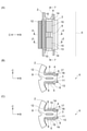
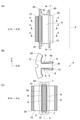
- FIG. 2 is a cross-sectional view taken along the line ⁇ of FIG. 2 (A).
- A) is a side view seen from the circumferential direction of the stator core of the conventional stator
- B) is a cross-sectional view taken along line ⁇ of (A)
- C) is a cross-sectional view taken along line ⁇ of (A). Is.
- One aspect of the present disclosure is a stator core in which a plurality of teeth project radially on the inner peripheral side of an annular stator core, the stator cores are arranged in the circumferential direction, an insulator covering the teeth, and a winding wound around the teeth via an insulator.
- the tooth has a pair of long sides extending along the central axis of the stator core and a pair of short sides adjacent to the long side and extending in the direction intersecting the central axis. It has a through hole that penetrates from the short side to the other short side, and the insulator has a pair of long side coverings that cover each of the pair of long sides and a pair of short sides that cover each of the pair of short sides.
- the long side covering portion and the short side surface covering portion adjacent to each other are integrated with each other, and each of the pair of short side surface covering portions penetrates.
- the long side covering includes an opening that is open while exposing the long side, and the portion exposed from the opening on the long side has higher thermal conductivity than the insulator. It is a stator in which a heat conductive substance is installed.
- Teeth are a pair of long sides extending along the central axis of the stator core, a pair of short sides adjacent to the long side and extending in a direction intersecting the central axis, and one short side to the other. It has a through hole portion that penetrates to the short side surface.
- the insulator has a pair of long side surface covering portions covering each of the pair of long side surfaces, a pair of short side surface covering portions covering each of the pair of short side surfaces, and a through hole filling portion filled in the through hole portion.
- the long side covering includes an opening that is open while exposing the long side.
- a heat conductive substance having higher heat conductivity than an insulator is installed in a portion exposed from the opening on the long side surface.
- the long side covering includes an opening.
- the long side surface covering portion and the short side surface covering portion adjacent to each other are integrated with each other, and each of the pair of short side surface covering portions is integrated with each other via the through hole filling portion. Therefore, the rigidity of the insulator and the stator core can be ensured.
- each of the pair of long side surface covering portions is a boundary between the pair of short side surface covering portions adjacent to each other so that the short side surface covering portion and the long side surface are flush with each other when viewed from the direction along the central axis.
- the long side surface may be covered between the two openings, including the two openings opened in.
- each of the pair of long side surface covering portions is adjacent to each other so that the short side surface covering portion and the long side surface are flush with each other when viewed from the direction along the central axis. Includes two openings opened at the boundary with. Therefore, undercut is less likely to occur when the insulator is insert-molded around the teeth of the stator core inserted in the mold, and it is easy to manufacture. Further, since each of the pair of long side surface covering portions covers the long side surface between the two openings, the distance between the winding and the teeth wound around the teeth via the insulator of the long side surface covering portions is stable.
- the motor provided with the stator 1 according to the present embodiment shown in FIG. 1 is applied to, for example, a supercharged engine for a 48V mild hybrid system, which is a two-stage supercharging system in which transient responsiveness and wide range are required. Will be done.
- the motor provided with the stator 1 according to the present embodiment realizes the electric compressor of the two-stage supercharging system and the electric assist turbo that regenerates the surplus turbine output at the time of high load.
- the stator 1 includes a stator core 2, an insulator 4, and a winding 5.
- a plurality of teeth 3 project in the radial direction R on the inner peripheral side of the annular stator core 2 and are arranged in the circumferential direction C.
- the stator core 2 is divided into a plurality of core pieces in the circumferential direction C for each tooth 3.
- the stator core 2 is composed of a plurality of steel plates laminated in a direction along the central axis X of the stator core 2. ing.
- the insulator 4 covers the teeth 3.
- the insulator 4 is a molded product made of a synthetic resin.
- the insulator 4 is formed by an insert molding method in which the insulator 4 is directly molded on the teeth 3 of the stator core 2.
- the winding 5 is wound around the teeth 3 via the insulator 4.
- the winding 5 is wound around one tooth 3 by a centralized winding.
- the winding 5 is an extra-thick single copper wire having a diameter of about several mm in order to reduce copper loss.
- the teeth 3 has a pair of long side surfaces 6 extending in a direction along the central axis X of the stator core 2. Further, the teeth 3 have a pair of short side surfaces 7 adjacent to the long side surface 6 and extending in a direction intersecting the central axis X, that is, in the circumferential direction C.
- the direction along the central axis X does not necessarily have to be the direction parallel to the central axis X, and may not be the direction orthogonal to the central axis X.
- the direction intersecting the central axis X does not necessarily have to be a direction orthogonal to the central axis X, and may not be a direction parallel to the central axis X.
- the directions in which the long side surface 6 and the short side surface 7 extend may not be the same on the entire surface thereof, and may vary depending on their positions.
- the teeth 3 has a through hole portion 8 penetrating from one short side surface 7 to the other short side surface 7.
- the width of the circumferential direction C of the teeth 3 is increased by the width of the circumferential direction C of the through hole portion 8. It is wider than the teeth 30 of the conventional stator core 20 as shown in FIGS. 4 (A), 4 (B) and 4 (C).
- the teeth 3 of the present embodiment are from the inner peripheral side to the outer peripheral side of the stator core 2 in the vicinity of the tip end portion on the inner peripheral side of the stator core 2.
- the teeth 3 of the present embodiment has a widening portion 17 provided on the outer peripheral side of the stator core 2 of the narrowing portion 16 and whose width in the circumferential direction C increases from the inner peripheral side to the outer peripheral side of the stator core 2. .. That is, in the teeth 3 of the present embodiment, a constriction is formed in the vicinity of the tip portion when viewed from the direction along the central axis X of the stator core 2. Further, the through hole portion 8 is formed on the outer peripheral side of the stator core 2 from the narrowed width portion 16.
- the insulator 4 has a pair of long side surface covering portions 9 that cover each of the pair of long side surfaces 6. Further, the insulator 4 has a pair of short side surface covering portions 10 that cover each of the pair of short side surfaces 7. Further, the insulator 4 has a through hole filling portion 11 filled in the through hole portion 8. Further, the insulator 4 has a base covering portion 12 that covers the base portion of the teeth 3 and a tip covering portion 13 that covers the tip portion of the teeth 3.
- the long side surface covering portion 9 and the short side surface covering portion 10 adjacent to each other are integrated with each other via the base covering portion 12 and the tip portion covering portion 13.
- each of the pair of short side covering portions 10 is integrated with each other via the through hole filling portion 11.
- the long side surface covering portion 9 includes an opening portion 14 which is opened while exposing the long side surface 6.
- six openings are formed in the insulator 4 of this embodiment. Four of the six openings are openings 14, exposing the long side surface 6.
- One of the six openings is an opening that exposes a part of the tip of the teeth 3 in the tip covering portion 13.
- the other of the six openings is an opening on the outer peripheral side of the stator core 2 along the shape of the base of the teeth 3 in the base covering portion 12, assuming that the stator core 2 is absent.
- each of the pair of long side surface covering portions 9 is adjacent to each other so that the short side surface covering portion 10 and the long side surface 6 are flush with each other when viewed from the direction along the central axis X. Includes two openings 14 that are open at the boundary with the pair of short side coverings 10. As shown in FIGS. 2A, 2B and 3, each of the pair of long side coverings 9 covers the long side 6 between the two openings 14.
- the short side surface covering portion 10 has a sufficient thickness so that the hard-to-bend extra-thick winding 5 does not come into contact with the long side surface 6 exposed at the opening 14.
- a heat conductive substance 15 having a higher heat conductivity than the insulator 4 is installed in a portion exposed from the opening 14 of the long side surface 6.
- the heat conductive substance 15 is a paste-like heat conductive compound such as silicone grease. By applying the paste-like heat conductive compound to the opening 14, the heat conductive substance 15 is installed in the portion exposed from the opening 14 on the long side surface 6.
- the thermal conductivity of the insulator 4 is about 0.3 to 0.5 W / mK.
- the thermal conductivity of the heat conductive substance 15 is about 2 W / mK.
- the heat conductive material 15 should be filled only between the first layer of the winding 5 wound in at least a plurality of layers and the teeth 3 of the stator core 2. Just do it. Since the extra-thick winding 5 is difficult to bend, the first layer of the winding 5 wound on a plurality of layers does not necessarily follow the teeth 3 and the insulator 4 over the entire circumference. Therefore, it is necessary that the heat conductive substance 15 is filled between the first layer of the winding 5 wound on the plurality of layers and the teeth 3 of the stator core 2.
- the winding radius of the winding 5 is always larger than that of the first layer over the entire circumference, so that the winding 5 and the second layer of the first layer are used. It is in close contact with the subsequent winding 5. If the windings 5 are in contact with each other, heat is easily transferred between the windings 5. Therefore, the heat conductive substance 15 may be filled only between the first layer of the winding wire 5 wound around at least a plurality of layers and the teeth 3 of the stator core 2.
- a highly fluid cast resin such as epoxy resin and silicone with improved thermal conductivity is poured and cured. It is common to increase the contact area between the winding and the stator core to reduce the thermal resistance.
- this method uses a large amount (100 g or more) of expensive cast resin and requires a curing time (about 30 to 60 minutes in the case of heat curing). Therefore, there is a problem that the component cost increases.
- the degree of adhesion between the insulator 40 and the stator core 20 is determined by an insert molding method in which the insulator 40 is directly molded on the teeth 30 of the stator core 20.
- a way to increase it has been proposed.
- the insulator 40 insert molding resin can wind the winding 5 around the teeth 30 with high tension in order to increase the rigidity of the stator core 20. Therefore, an extra-thick single copper wire can be adopted for the winding 5, and the reliability of the connection portion of the winding 5 can be improved while handling a large current.
- the extra-thick winding 5 wound around the teeth 30 is difficult to bend and is difficult to follow the teeth 30 and the insulator 40 of the stator core 20, as shown in FIG. 4C, the winding 5 and the insulator 40 are in close contact with each other. Is only near the boundary between the long side surface covering portion 9 and the short side surface covering portion 10, and contact with other portions cannot be obtained. Therefore, it becomes difficult for heat to be transferred from the winding wire 5 to the stator core 20, and there arises a problem that the heat extraction capacity is insufficient.
- the plurality of teeth 3 are on the inner peripheral side of the annular stator core 2.
- a stator 1 having a stator core 2 protruding in the radial direction R and arranged in the circumferential direction C, an insulator 4 covering the teeth 3, and a winding 5 wound around the teeth 3 via the insulator 4, the teeth 3 Is a pair of long side surfaces 6 extending in a direction along the central axis X of the stator core 2, a pair of short side surfaces extending in a direction intersecting the central axis X, and one short side surface 7 to the other short side surface. It has a through hole portion 8 penetrating to the side surface 7.
- the insulator 4 includes a pair of long side surface covering portions 9 that cover each of the pair of long side surfaces 6, a pair of short side surface covering portions 10 that cover each of the pair of short side surfaces 7, and a through hole filled in the through hole portion 8. It has a filling portion 11.
- the long side surface covering portion 9 includes an opening portion 14 which is opened while exposing the long side surface 6.
- a heat conductive substance 15 having a higher heat conductivity than that of the insulator 4 is installed in a portion exposed from the opening 14 of the long side surface 6.
- the long side covering portion 9 includes an opening 14. However, the long side surface covering portion 9 and the short side surface covering portion 10 adjacent to each other are integrated with each other, and each of the pair of short side surface covering portions 10 is integrated with each other via the through hole filling portion 11. Therefore, the rigidity of the insulator 4 and the stator core 2 can be ensured.
- the rigidity of the insulator 4 is maintained by the resin clinging to the teeth 3 of the stator core 2 due to the molding shrinkage of the resin.
- the insulator 4 surrounds the entire circumference of the teeth 3 of the stator core 2, the cross section of the insulator 4 is closed, and the rigidity of the insulator 4 becomes the rigidity of the teeth 3 of the stator core 2 and becomes maximum.
- the hole is formed on the long side surface 6, the hole is opened on the entire surface of the long side surface 6 of the tooth 3 of the stator core 2 due to the limitation of molding (die cutting), and the insulator 4 is formed. Only the short side 7 will hug the teeth 3. Therefore, the material that supports the insulator 4 near the boundary between the long side surface covering portion 9 and the short side surface covering portion 10 is minimized, and the rigidity is reduced.
- the through hole portion 8 is provided inside the stator core 2, and the resin of the through hole filling portion 11 filled in the through hole portion 8 is used to cover the short side surface of the teeth 3 of the stator core 2 on the short side surface 7.
- the insulator 4 will be attached to the teeth 3 of the stator core 2 with a surface area similar to that surrounding the insulator 4, and the rigidity is relatively well maintained.
- the winding 5 and the insulator 4 are in close contact with each other in the long side surface covering portion 9 and the short side surface covering portion 10. Only near the boundary with. Therefore, if the insulator 4 comes into contact with the winding 5 only in the vicinity of the boundary, the insulator 4 other than the vicinity of the boundary is removed, and the space between the teeth 3 and the winding 5 of the stator core 2 is filled with a heat conductive substance. This makes it easier for heat to be transferred from the winding 5 to the stator core 2.
- each of the pair of long side surface covering portions 9 is adjacent to each other so that the short side surface covering portion 10 and the long side surface 6 are flush with each other when viewed from the direction along the central axis X.
- each of the pair of long side surface covering portions 9 covers the long side surface 6 between the two openings 14, the winding 5 and the teeth 3 wound around the teeth 3 via the insulator 4 of the long side surface covering portions 9. The distance to and is stable.
- the insulator 4 when the insulator 4 is molded by insert molding on the teeth 3 of the stator core 2, considering that the dividing direction of the molding die is the direction along the central axis X, in order to prevent undercuts from occurring.
- the opening 14 needs to be open so that the short side surface covering portion 10 and the long side surface 6 are flush with each other when viewed from the direction along the central axis X. In this case, the proximity of the winding wire 5 and the long side surface 6 becomes a problem.
- the opening 14 is arranged only in the portion of the teeth 3 where the winding 5 does not come into contact.
- An insulator 4 is formed at the center of the short side surface 7 and the long side surface 6.
- the winding 5 is wound around the tooth 3 in a hexagonal shape or an octagonal shape when viewed from the radial direction R, so that the distance between the stator core 2 and the winding 5 is stable. Further, as a result, the force with which the winding wire 5 is pressed against the teeth 3 by the tension increases, so that the amount of the heat conductive substance 15 used is reduced and the ease of heat transfer is stabilized.
- the thickness of the opening 14 which is the undercut removing portion is thicker than the short side surface 7 of the teeth 3 while guiding the bending of the winding 5 halfway.
- the heat conductive substance 15 may be a sheet-shaped heat transfer body sandwiched between the winding 5 and the teeth 3 of the stator core 2 instead of the heat conductive compound.
- the heat conductive substance 15 may be a molding material (potting material) filled in the entire area of the electric motor including the opening 14.
- stator on one side of the present disclosure, it is possible to ensure the rigidity of the insulator and the stator core while making it easier for heat to be transferred from the winding to the stator core.
Landscapes
- Engineering & Computer Science (AREA)
- Power Engineering (AREA)
- Insulation, Fastening Of Motor, Generator Windings (AREA)
- Iron Core Of Rotating Electric Machines (AREA)
Abstract
Description
2 ステータコア
3 ティース
4 インシュレータ
5 巻線
6 長側面
7 短側面
8 貫通孔部
9 長側面被覆部
10 短側面被覆部
11 貫通孔充填部
12 基部被覆部
13 先端部被覆部
14 開口部
15 熱伝導性物質
16 縮幅部
17 拡幅部
20 ステータコア
30 ティース
40 インシュレータ
X 中心軸
R 径方向
C 周方向
Claims (2)
- 複数のティースが円環状のステータコアの内周側の径方向に突出し、周方向に配列された前記ステータコアと、
前記ティースを覆うインシュレータと、
前記インシュレータを介して前記ティースに巻かれた巻線と、
を備え、
前記ティースは、
前記ステータコアの中心軸に沿った方向に延在する一対の長側面と、
前記長側面に隣接し、前記中心軸に交差する方向に延在する一対の短側面と、
一方の前記短側面から他方の前記短側面へと貫通する貫通孔部と、
を有し、
前記インシュレータは、
一対の前記長側面のそれぞれを覆う一対の長側面被覆部と、
一対の前記短側面のそれぞれを覆う一対の短側面被覆部と、
前記貫通孔部に充填された貫通孔充填部と、
を有し、
互いに隣接する前記長側面被覆部と前記短側面被覆部とは、互いに一体化され、
一対の前記短側面被覆部のそれぞれは前記貫通孔充填部を介して互いに一体化され、
前記長側面被覆部は、前記長側面を露出させつつ開口した開口部を含み、
前記長側面の前記開口部から露出した部位には、前記インシュレータより高い熱伝導性を有する熱伝導性物質が設置されている、固定子。 - 一対の前記長側面被覆部のそれぞれは、
前記中心軸に沿った方向から視て前記短側面被覆部と前記長側面とが同一平面になるように、互いに隣接する一対の前記短側面被覆部との境界で開口した2つの前記開口部を含み、
2つの前記開口部の間で前記長側面を覆う、請求項1に記載の固定子。
Priority Applications (4)
| Application Number | Priority Date | Filing Date | Title |
|---|---|---|---|
| DE112021002313.6T DE112021002313T5 (de) | 2020-08-24 | 2021-08-05 | Stator |
| CN202180034435.6A CN115606077B (zh) | 2020-08-24 | 2021-08-05 | 定子 |
| JP2022545612A JP7371790B2 (ja) | 2020-08-24 | 2021-08-05 | 固定子 |
| US18/068,749 US12237745B2 (en) | 2020-08-24 | 2022-12-20 | Stator with insulated teeth |
Applications Claiming Priority (2)
| Application Number | Priority Date | Filing Date | Title |
|---|---|---|---|
| JP2020-140972 | 2020-08-24 | ||
| JP2020140972 | 2020-08-24 |
Related Child Applications (1)
| Application Number | Title | Priority Date | Filing Date |
|---|---|---|---|
| US18/068,749 Continuation US12237745B2 (en) | 2020-08-24 | 2022-12-20 | Stator with insulated teeth |
Publications (1)
| Publication Number | Publication Date |
|---|---|
| WO2022044765A1 true WO2022044765A1 (ja) | 2022-03-03 |
Family
ID=80353117
Family Applications (1)
| Application Number | Title | Priority Date | Filing Date |
|---|---|---|---|
| PCT/JP2021/029183 Ceased WO2022044765A1 (ja) | 2020-08-24 | 2021-08-05 | 固定子 |
Country Status (5)
| Country | Link |
|---|---|
| US (1) | US12237745B2 (ja) |
| JP (1) | JP7371790B2 (ja) |
| CN (1) | CN115606077B (ja) |
| DE (1) | DE112021002313T5 (ja) |
| WO (1) | WO2022044765A1 (ja) |
Cited By (1)
| Publication number | Priority date | Publication date | Assignee | Title |
|---|---|---|---|---|
| WO2025109723A1 (ja) * | 2023-11-22 | 2025-05-30 | ファナック株式会社 | ステータ |
Citations (3)
| Publication number | Priority date | Publication date | Assignee | Title |
|---|---|---|---|---|
| JP2008283730A (ja) * | 2007-05-08 | 2008-11-20 | Sumitomo Electric Ind Ltd | 電動機用分割固定子、この分割固定子を備える電動機用固定子、この電動機用固定子を備える電動機及び電動機用分割固定子の製造方法 |
| JP2010136571A (ja) * | 2008-12-08 | 2010-06-17 | Toyota Motor Corp | 回転電機用ステータ |
| JP2013013192A (ja) * | 2011-06-28 | 2013-01-17 | Nissan Motor Co Ltd | ステーター及びインシュレーター |
Family Cites Families (8)
| Publication number | Priority date | Publication date | Assignee | Title |
|---|---|---|---|---|
| US3339097A (en) * | 1965-08-10 | 1967-08-29 | Eastman Mfg Co Inc | Bobbin and pole construction |
| JP4415433B2 (ja) * | 1999-10-25 | 2010-02-17 | パナソニック株式会社 | 電動機 |
| US6509665B1 (en) | 1999-10-25 | 2003-01-21 | Matsushita Electric Industial Co., Ltd. | Motor having stator with insulator of high heat-conductivity |
| JP2007215335A (ja) * | 2006-02-10 | 2007-08-23 | Sumitomo Electric Ind Ltd | 電動機用固定子及びこの固定子を備える電動機 |
| JP2010119191A (ja) * | 2008-11-12 | 2010-05-27 | Yaskawa Electric Corp | 電動機の固定子および電動機 |
| JP5843156B2 (ja) * | 2011-06-13 | 2016-01-13 | 日本電産株式会社 | ステータユニットおよびモータ |
| JP5419956B2 (ja) * | 2011-12-20 | 2014-02-19 | 三菱電機株式会社 | 電動機の固定子及び絶縁シートの製造方法 |
| JP2013247696A (ja) * | 2012-05-23 | 2013-12-09 | Jtekt Corp | 回転電機 |
-
2021
- 2021-08-05 CN CN202180034435.6A patent/CN115606077B/zh active Active
- 2021-08-05 DE DE112021002313.6T patent/DE112021002313T5/de active Pending
- 2021-08-05 WO PCT/JP2021/029183 patent/WO2022044765A1/ja not_active Ceased
- 2021-08-05 JP JP2022545612A patent/JP7371790B2/ja active Active
-
2022
- 2022-12-20 US US18/068,749 patent/US12237745B2/en active Active
Patent Citations (3)
| Publication number | Priority date | Publication date | Assignee | Title |
|---|---|---|---|---|
| JP2008283730A (ja) * | 2007-05-08 | 2008-11-20 | Sumitomo Electric Ind Ltd | 電動機用分割固定子、この分割固定子を備える電動機用固定子、この電動機用固定子を備える電動機及び電動機用分割固定子の製造方法 |
| JP2010136571A (ja) * | 2008-12-08 | 2010-06-17 | Toyota Motor Corp | 回転電機用ステータ |
| JP2013013192A (ja) * | 2011-06-28 | 2013-01-17 | Nissan Motor Co Ltd | ステーター及びインシュレーター |
Cited By (1)
| Publication number | Priority date | Publication date | Assignee | Title |
|---|---|---|---|---|
| WO2025109723A1 (ja) * | 2023-11-22 | 2025-05-30 | ファナック株式会社 | ステータ |
Also Published As
| Publication number | Publication date |
|---|---|
| DE112021002313T5 (de) | 2023-02-09 |
| CN115606077A (zh) | 2023-01-13 |
| JPWO2022044765A1 (ja) | 2022-03-03 |
| US20230122181A1 (en) | 2023-04-20 |
| US12237745B2 (en) | 2025-02-25 |
| JP7371790B2 (ja) | 2023-10-31 |
| CN115606077B (zh) | 2025-08-19 |
Similar Documents
| Publication | Publication Date | Title |
|---|---|---|
| US5592731A (en) | Method of constructing a stator | |
| US12062960B2 (en) | Method for producing a stator for an electric machine | |
| CN102044916A (zh) | 磁性铁芯以及其制造方法、轴隙式旋转电机、静止机 | |
| JP6918026B2 (ja) | アキシャルギャップ型回転電機の製造方法 | |
| JP3882721B2 (ja) | 回転電機の冷却構造及びその製造方法 | |
| JP2011103733A (ja) | 回転電機 | |
| JP6814568B2 (ja) | 積層鉄心 | |
| CN101051768B (zh) | 定子组件和制造方法 | |
| JP2016039736A (ja) | 可動電機、コイルの製造方法、電線 | |
| JP7371790B2 (ja) | 固定子 | |
| CN1525624B (zh) | 带有叠片转子的电机 | |
| CN112117843A (zh) | 定子、电机、车辆和用于生产定子的方法 | |
| JP5151309B2 (ja) | 回転電機 | |
| JP4682989B2 (ja) | ステータの製造方法 | |
| JP2018082517A (ja) | 電動機 | |
| JP3603815B2 (ja) | 回転電機 | |
| US20240380282A1 (en) | Electric machine, stator and method of assembly | |
| JP3655269B2 (ja) | モータ及びその製造方法 | |
| CN108028569B (zh) | 电机和制造方法 | |
| CN117691774A (zh) | 一种小功率盘式电机定子及其制造方法和盘式电机 | |
| JP4710177B2 (ja) | 回転電機の冷却構造及びその製造方法 | |
| JP2007082276A (ja) | ステータコアを構成する樹脂モジュール、ステータコア及びそれを用いたモータ | |
| JPS6259538B2 (ja) | ||
| CN217362680U (zh) | 盘式电机的定子 | |
| KR102481461B1 (ko) | 전기자동차용 모터 하우징 및 그 제조방법 |
Legal Events
| Date | Code | Title | Description |
|---|---|---|---|
| 121 | Ep: the epo has been informed by wipo that ep was designated in this application |
Ref document number: 21861193 Country of ref document: EP Kind code of ref document: A1 |
|
| ENP | Entry into the national phase |
Ref document number: 2022545612 Country of ref document: JP Kind code of ref document: A |
|
| 122 | Ep: pct application non-entry in european phase |
Ref document number: 21861193 Country of ref document: EP Kind code of ref document: A1 |
|
| WWG | Wipo information: grant in national office |
Ref document number: 202180034435.6 Country of ref document: CN |