WO2022038954A1 - アルミニウム合金溶加材、アルミニウム合金製溶接構造体及びアルミニウム材の溶接方法 - Google Patents
アルミニウム合金溶加材、アルミニウム合金製溶接構造体及びアルミニウム材の溶接方法 Download PDFInfo
- Publication number
- WO2022038954A1 WO2022038954A1 PCT/JP2021/027264 JP2021027264W WO2022038954A1 WO 2022038954 A1 WO2022038954 A1 WO 2022038954A1 JP 2021027264 W JP2021027264 W JP 2021027264W WO 2022038954 A1 WO2022038954 A1 WO 2022038954A1
- Authority
- WO
- WIPO (PCT)
- Prior art keywords
- aluminum alloy
- welding
- aluminum
- filler material
- speed
- Prior art date
- Legal status (The legal status is an assumption and is not a legal conclusion. Google has not performed a legal analysis and makes no representation as to the accuracy of the status listed.)
- Ceased
Links
Images




Classifications
-
- B—PERFORMING OPERATIONS; TRANSPORTING
- B23—MACHINE TOOLS; METAL-WORKING NOT OTHERWISE PROVIDED FOR
- B23K—SOLDERING OR UNSOLDERING; WELDING; CLADDING OR PLATING BY SOLDERING OR WELDING; CUTTING BY APPLYING HEAT LOCALLY, e.g. FLAME CUTTING; WORKING BY LASER BEAM
- B23K35/00—Rods, electrodes, materials, or media, for use in soldering, welding, or cutting
- B23K35/22—Rods, electrodes, materials, or media, for use in soldering, welding, or cutting characterised by the composition or nature of the material
- B23K35/24—Selection of soldering or welding materials proper
- B23K35/28—Selection of soldering or welding materials proper with the principal constituent melting at less than 950°C
- B23K35/286—Al as the principal constituent
-
- B—PERFORMING OPERATIONS; TRANSPORTING
- B23—MACHINE TOOLS; METAL-WORKING NOT OTHERWISE PROVIDED FOR
- B23K—SOLDERING OR UNSOLDERING; WELDING; CLADDING OR PLATING BY SOLDERING OR WELDING; CUTTING BY APPLYING HEAT LOCALLY, e.g. FLAME CUTTING; WORKING BY LASER BEAM
- B23K26/00—Working by laser beam, e.g. welding, cutting or boring
- B23K26/20—Bonding
- B23K26/21—Bonding by welding
- B23K26/24—Seam welding
- B23K26/242—Fillet welding, i.e. involving a weld of substantially triangular cross section joining two parts
-
- B—PERFORMING OPERATIONS; TRANSPORTING
- B23—MACHINE TOOLS; METAL-WORKING NOT OTHERWISE PROVIDED FOR
- B23K—SOLDERING OR UNSOLDERING; WELDING; CLADDING OR PLATING BY SOLDERING OR WELDING; CUTTING BY APPLYING HEAT LOCALLY, e.g. FLAME CUTTING; WORKING BY LASER BEAM
- B23K26/00—Working by laser beam, e.g. welding, cutting or boring
- B23K26/20—Bonding
- B23K26/32—Bonding taking account of the properties of the material involved
-
- B—PERFORMING OPERATIONS; TRANSPORTING
- B23—MACHINE TOOLS; METAL-WORKING NOT OTHERWISE PROVIDED FOR
- B23K—SOLDERING OR UNSOLDERING; WELDING; CLADDING OR PLATING BY SOLDERING OR WELDING; CUTTING BY APPLYING HEAT LOCALLY, e.g. FLAME CUTTING; WORKING BY LASER BEAM
- B23K26/00—Working by laser beam, e.g. welding, cutting or boring
- B23K26/346—Working by laser beam, e.g. welding, cutting or boring in combination with welding or cutting covered by groups B23K5/00 - B23K25/00, e.g. in combination with resistance welding
- B23K26/348—Working by laser beam, e.g. welding, cutting or boring in combination with welding or cutting covered by groups B23K5/00 - B23K25/00, e.g. in combination with resistance welding in combination with arc heating, e.g. tungsten inert gas [TIG], metal inert gas [MIG] or plasma welding
-
- B—PERFORMING OPERATIONS; TRANSPORTING
- B23—MACHINE TOOLS; METAL-WORKING NOT OTHERWISE PROVIDED FOR
- B23K—SOLDERING OR UNSOLDERING; WELDING; CLADDING OR PLATING BY SOLDERING OR WELDING; CUTTING BY APPLYING HEAT LOCALLY, e.g. FLAME CUTTING; WORKING BY LASER BEAM
- B23K9/00—Arc welding or cutting
- B23K9/23—Arc welding or cutting taking account of the properties of the materials to be welded
-
- C—CHEMISTRY; METALLURGY
- C22—METALLURGY; FERROUS OR NON-FERROUS ALLOYS; TREATMENT OF ALLOYS OR NON-FERROUS METALS
- C22C—ALLOYS
- C22C21/00—Alloys based on aluminium
- C22C21/02—Alloys based on aluminium with silicon as the next major constituent
-
- C—CHEMISTRY; METALLURGY
- C22—METALLURGY; FERROUS OR NON-FERROUS ALLOYS; TREATMENT OF ALLOYS OR NON-FERROUS METALS
- C22C—ALLOYS
- C22C21/00—Alloys based on aluminium
- C22C21/02—Alloys based on aluminium with silicon as the next major constituent
- C22C21/04—Modified aluminium-silicon alloys
-
- B—PERFORMING OPERATIONS; TRANSPORTING
- B23—MACHINE TOOLS; METAL-WORKING NOT OTHERWISE PROVIDED FOR
- B23K—SOLDERING OR UNSOLDERING; WELDING; CLADDING OR PLATING BY SOLDERING OR WELDING; CUTTING BY APPLYING HEAT LOCALLY, e.g. FLAME CUTTING; WORKING BY LASER BEAM
- B23K2101/00—Articles made by soldering, welding or cutting
- B23K2101/18—Sheet panels
-
- B—PERFORMING OPERATIONS; TRANSPORTING
- B23—MACHINE TOOLS; METAL-WORKING NOT OTHERWISE PROVIDED FOR
- B23K—SOLDERING OR UNSOLDERING; WELDING; CLADDING OR PLATING BY SOLDERING OR WELDING; CUTTING BY APPLYING HEAT LOCALLY, e.g. FLAME CUTTING; WORKING BY LASER BEAM
- B23K2103/00—Materials to be soldered, welded or cut
- B23K2103/08—Non-ferrous metals or alloys
- B23K2103/10—Aluminium or alloys thereof
-
- B—PERFORMING OPERATIONS; TRANSPORTING
- B23—MACHINE TOOLS; METAL-WORKING NOT OTHERWISE PROVIDED FOR
- B23K—SOLDERING OR UNSOLDERING; WELDING; CLADDING OR PLATING BY SOLDERING OR WELDING; CUTTING BY APPLYING HEAT LOCALLY, e.g. FLAME CUTTING; WORKING BY LASER BEAM
- B23K35/00—Rods, electrodes, materials, or media, for use in soldering, welding, or cutting
- B23K35/02—Rods, electrodes, materials, or media, for use in soldering, welding, or cutting characterised by mechanical features, e.g. shape
- B23K35/0255—Rods, electrodes, materials, or media, for use in soldering, welding, or cutting characterised by mechanical features, e.g. shape for use in welding
- B23K35/0261—Rods, electrodes or wires
Definitions
- the present invention relates to an aluminum alloy filler that can be used for melt welding such as arc welding, an aluminum alloy welded structure manufactured using the aluminum alloy filler, and aluminum using the aluminum alloy filler. It relates to a method of welding a material, and particularly to an aluminum alloy filler material suitable for welding at a high welding speed.
- the filler metal used for welding aluminum materials needs to consider the degree of cracking during welding, mechanical properties, corrosion resistance, high temperature characteristics, etc. in combination with the base metal. Specific guidelines are shown in JIS Z 3604, and filler metal made of aluminum alloys such as 4000 series, 5000 series and 6000 series is used depending on the application.
- 4043 which has Al and 5% by mass of Si as the standard composition
- 4047 which has Al and 12% by mass of Si as the standard composition.
- 4043 is used for welding aluminum alloys and castings that are prone to weld cracking because of its high resistance to high temperature cracking of the weld metal.
- the strength and toughness of the welded portion tend to be low, and it is necessary to improve the joint strength by optimizing the welding conditions such as welding current, welding voltage and welding speed.
- the welding conditions such as welding current, welding voltage and welding speed.
- there is a limit only to the optimization of the welding conditions and there is a problem that it is not practical for a welded portion that requires high strength and excellent toughness.
- Patent Document 1 Japanese Unexamined Patent Publication No. 2006-218491
- a welded joint made of an aluminum alloy material which can be applied to MIG welding and has a welded portion having high joint strength and high toughness is obtained.
- a filler material for aluminum or an aluminum alloy that can be used it contains 4.5 to 13.0% of Si and 10 to 400 ppm of Sr by mass, from the balance Al and unavoidable impurities.
- the welding speed studied in Patent Document 1 is 0.75 m / min, and in addition to forming a joint portion having excellent mechanical properties, welding is performed at a high speed like hybrid laser welding. The fact is that there is no filler metal that does not easily crack even if it is used.
- an object of the present invention is to form an aluminum alloy filler material having excellent strength and toughness in high-speed joining of an aluminum alloy and less likely to cause welding cracks. It is an object of the present invention to provide an aluminum alloy welded structure manufactured by using the aluminum alloy filler material and a method of joining an aluminum material using the aluminum alloy filler material. More specifically, an aluminum alloy filler material in which welding cracks are unlikely to occur even when high-speed joining with a welding speed exceeding 1 m / min is performed, and an aluminum alloy welded structure manufactured using the aluminum alloy filler material. It is an object of the present invention to provide a method for welding an aluminum material using a body and the aluminum alloy filler material.
- the present inventors have obtained an appropriate amount of a surface active element that lowers the surface tension of molten aluminum. We have found that it is extremely effective to include it, and have reached the present invention.
- the present invention It consists of aluminum containing a surface-active element that reduces the surface tension of molten aluminum.
- the surface active element is at least one of Ca, Sr and Ba, and the surface active element is at least one of Ca, Sr and Ba.
- the content of the surfactant is 0.05 to 0.50% by mass.
- an aluminum alloy filler material for high speed bonding is provided.
- the surface tension of the molten aluminum can be lowered, and the fluidity is improved due to the improvement of the wettability of the molten filler material. Weld cracking can be suppressed even if high-speed joining is performed.
- Ca, Sr and Ba belong to the 4th to 6th periods of Group 2 in the periodic table of elements.
- the amount of the surface-active element added is extremely important in order to suppress welding cracks during high-speed joining, and by containing 0.05 to 0.50% by mass of the surface-active element, the welding speed can be increased to 1 m / min. Weld cracking in high-speed joining that exceeds can be efficiently suppressed. This effect becomes remarkable at a welding speed of 2 m / min and further becomes remarkable at a welding speed of 4 m / min.
- the surface active element is Sr.
- Sr as a surface active element
- the surface tension of molten aluminum can be reduced more efficiently than when Ca is added.
- the eutectic Si phase is granulated finer more efficiently than when Ba is added, and the ductility and toughness of the welded portion can be improved.
- Si is further contained in an amount of 4 to 13% by mass.
- Si content it is preferable that Si is further contained in an amount of 4 to 13% by mass.
- the present invention also provides an aluminum alloy filler for hybrid laser welding, which comprises the composition of the aluminum alloy filler for high-speed bonding of the present invention.
- the aluminum alloy filler material for hybrid laser bonding of the present invention is an aluminum alloy filler material used in a bonding process that combines laser welding and arc welding.
- Hybrid laser bonding is a bonding technology that guides an arc to the cathode point generated by the preceding laser and welds it, and realizes improved welding stability, suppression of defect formation, increased bonding speed, and increased penetration depth. can do.
- a bonding speed of 5 m / min or more may be set, but even under such high-speed bonding conditions, the aluminum alloy filler material for herbal lid laser bonding of the present invention can be used. Weld cracks can be suppressed extremely effectively.
- the present invention also provides an aluminum alloy welded structure characterized in that the Sr content of the welded portion is 0.03% by mass or more.
- the aluminum alloy welded structure of the present invention can be easily obtained by welding the aluminum alloy material using the aluminum alloy filler material for high-speed joining of the present invention.
- the aluminum alloy filler material for high-speed joining of the present invention contains 0.05 to 0.50% by mass of Sr, and the Sr is present in the joint, but the final Sr in the joint is present. It is necessary to consider the influence of dilution by the aluminum alloy material, which is the material to be joined, for the content. When the aluminum alloy material contains Sr, the Sr content of the joint portion may be higher than the Sr content of the aluminum alloy filler material for high-speed joining.
- the average particle size of the equiaxed grains formed in the vicinity of the surface of the welded portion in the fine structure of the welded portion is 150 ⁇ m or less.
- columnar crystals are formed from the boundary between the welded portion and the base metal (bonded material) in the solidification direction of the molten pool, and equiaxial microstructures are continuously formed from the columnar crystals. be. That is, equiaxed grains are formed near the surface of the welded portion that is finally solidified.
- the present invention also provides a method for welding an aluminum material, which comprises performing welding using the aluminum alloy filler material for high-speed joining of the present invention.
- a method for welding an aluminum material of the present invention it is preferable to use hybrid laser welding.
- the welding speed is 1 m / min or more. If the welding speed is increased, it becomes difficult to suppress welding cracks in the welded portion. However, by performing hybrid laser bonding using the aluminum alloy filler material for high-speed bonding of the present invention, excellent welding is extremely efficient. The part can be formed.
- a joint portion having excellent strength and toughness is formed, and the aluminum alloy filler material in which welding cracks are less likely to occur and the aluminum alloy filler material are used. It is possible to provide an aluminum alloy welded structure and a method for welding an aluminum material using the aluminum alloy filler material. More specifically, an aluminum alloy filler material in which welding cracks are unlikely to occur even when high-speed joining with a welding speed exceeding 1 m / min is performed, and an aluminum alloy welded structure manufactured using the aluminum alloy filler material. It is possible to provide a method for welding an aluminum material using a body and the aluminum alloy filler material.
- FIG. 9 is an enlarged photograph of the apex of the welded portion in FIG. It is an appearance photograph of the weld bead obtained in the comparative example. It is a microstructure of a weld bead obtained by a weld wire made of an aluminum alloy having the composition of Comparative Example 1. It is a vertical cross-sectional photograph of a weld bead obtained by a welding wire made of an aluminum alloy having the composition of Comparative Example 1. It is an enlarged photograph of the apex of a welded portion in FIG.
- the aluminum alloy filler of the present invention is made of aluminum containing a surface-active element that reduces the surface tension of molten aluminum, and the surface-active element is at least one of Ca, Sr, and Ba. It is an aluminum alloy filler material for high-speed bonding, characterized in that the content of a surface active element is 0.05 to 0.50% by mass. Further, the aluminum alloy filler material for high-speed welding can be suitably used as an aluminum alloy filler material for hybrid laser welding.
- each component will be described in detail.
- Essential additive elements surfactant elements
- Sr 0.05 to 0.50% by mass
- the Sr content is preferably 0.15% by mass or more.
- Sr may form a coarse compound if added in a large amount.
- the Sr content is preferably 0.30% by mass or less, and more preferably 0.20% by mass or less.
- Ca 0.05 to 0.50% by mass
- the wettability is improved due to the decrease in the surface tension of the molten aluminum, and weld cracking in high-speed joining can be suppressed.
- the addition of Ca makes the eutectic Si structure finer, which mainly contributes to elongation.
- the crystallized product becomes coarse and adversely affects the toughness.
- Ba 0.05 to 0.50% by mass
- the total content of the added elements is set to 0.05 to 0.50% by mass to prevent welding cracks during high-speed joining. At the same time, it is possible to suppress the formation of coarse compounds and blow holes.
- the composition is not particularly limited as long as the effect of the present invention is not impaired, and various conventionally known aluminum fillers can be used. ..
- the composition may be such that the above-mentioned surfactant element is added to the composition of the 4000 series filler material, the 5000 series filler material and the 6000 series filler material.
- the melting point and the fluidity of the molten metal it is preferable to use the composition of the 4000 series filler metal. Further, it is preferable to contain an appropriate amount of Si.
- Si 4 to 13% by mass
- the Si content By setting the Si content to 4% by mass or more, the melting point can be sufficiently lowered and the fluidity of the molten aluminum at the time of joining can be ensured. Further, by setting the Si content to 13% by mass or less, it is possible to suppress a decrease in elongation of the joint portion due to the formation of crystallization that is the starting point of fracture.
- the specific form of the aluminum alloy filler material of the present invention is not particularly limited as long as the effect of the present invention is not impaired, and can be various conventionally known forms of the filler material.
- it can be rod-shaped, continuous wire-shaped, powder-shaped, granular, or the like.
- the aluminum alloy welded structure of the present invention is an aluminum alloy welded structure characterized in that the Sr content of the welded portion is 0.03% by mass or more.
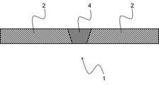
- FIG. 1 shows a schematic cross-sectional view of the vicinity of the welded portion in one aspect of the aluminum alloy welded structure of the present invention.
- FIG. 1 shows a cross section perpendicular to the weld line, and the aluminum alloy structure 1 has a structure in which the aluminum alloy materials 2 are joined to each other by the welded portion 4.
- the Sr content of the welded portion 4 is 0.03% by mass or more.
- the Sr content of the welded portion 4 is preferably 0.05% by mass or more, and more preferably 0.10% by mass or more.
- the method for measuring the Sr content of the welded portion 4 is not particularly limited, and various conventionally known measuring methods can be used. For example, it can be calculated from the dilution rate obtained from the weld cross-sectional area, or SEM-EDS measurement, EPMA measurement, emission spectroscopic analysis and the like can be used.
- composition of the welded portion 4 other than Sr is not particularly limited as long as the effect of the present invention is not impaired, and various conventionally known compositions of aluminum fillers can be used.
- the composition may be such that 0.03% by mass or more of Sr is added to the composition of the 4000 series filler material, the 5000 series filler material and the 6000 series filler material.
- the shape and size of the welded portion 4 are not particularly limited as long as the effects of the present invention are not impaired, and may be appropriately adjusted according to the shape and size of the aluminum alloy material 2 and the desired joint characteristics.
- the welded portion 4 is preferably formed over the entire interface to be joined, but may be partially formed if the mechanical properties of the joint are not high.
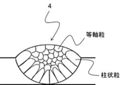
- the microstructure of the welded portion 4 in FIG. 1 is schematically shown in FIG.
- a structure composed of columnar crystals is formed from the boundary with the unmelted aluminum alloy material 2 in the solidification direction, and a structure composed of equiaxed crystal grains is formed as the solidification progresses.
- the average particle size of the equiaxed grains formed in the vicinity of the surface of the welded portion 4 (final solidification side) is 150 ⁇ m or less.
- the method for obtaining the average particle size of the equiaxed grains formed in the vicinity of the surface of the welded portion 4 is not particularly limited, but can be obtained, for example, by the intersection method using a cross-sectional photograph including the welded portion 4. Specifically, a straight line of an arbitrary length is drawn on a cross-sectional photograph, the intersections of the crystal grains and the straight line are counted, and then the value obtained by dividing the length of the straight line by the number of intersections is used as the average particle size. can. In this case, it is preferable to draw a straight line so that the number of intersections is 100 or more.
- composition, size and shape of the aluminum alloy material 2 are not particularly limited as long as the effects of the present invention are not impaired, and aluminum alloy materials having various conventionally known compositions, sizes and shapes can be used.
- the aluminum alloy structure 1 may have a structure in which the aluminum alloy materials 2 are joined to each other by the welded portion 4, and may have a region made of a material other than the aluminum alloy.
- the aluminum alloy material 2 may be joined to a steel material, a magnesium alloy material, a titanium alloy material, or the like.
- the welding method of the aluminum material of the present invention will be described by taking the case of manufacturing the aluminum alloy structure 1 as an example.
- the aluminum alloy structure 1 can be easily manufactured by welding the aluminum alloy materials 2 to each other using the aluminum alloy filler material for high-speed joining of the present invention.
- the welding method is not particularly limited as long as the effect of the present invention is not impaired, and a conventionally known welding method can be used.
- the method for welding an aluminum material of the present invention is characterized in that hybrid laser welding is performed using the aluminum alloy filler material for high-speed joining of the present invention.
- hybrid laser welding is performed using the aluminum alloy filler material for high-speed joining of the present invention.
- hybrid laser welding it is possible to improve the stability of welding, suppress defect formation, increase the joining speed, increase the penetration depth, and the like. Further, since the aluminum alloy filler material for high-speed bonding of the present invention is used, welding cracks can be suppressed even if the bonding speed is increased, and the advantages of hybrid laser welding can be fully enjoyed.
- the structure of the welded portion 4 can be miniaturized by setting the welding speed to 11 m / min or more. Further, by setting the welding speed to 5 m / min or more, the average particle size of the equiaxed grains formed in the vicinity of the surface of the welded portion 4 can be set to 150 ⁇ m or less.
- the welding speed is 5 m / min or more, it becomes difficult to suppress welding cracks in the welded portion 4, but it is extremely possible to perform hybrid laser bonding using the aluminum alloy filler material for high-speed bonding of the present invention. It is possible to efficiently form a good welded portion 4.
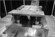
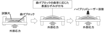
- FIG. 4 A schematic diagram of the valest train test is shown in FIG. 4, in which welding is performed with an external stress applied to the material to be joined, and the tensile stress applied to the welded portion promotes weld cracking.
- the bending radius in the valest train test was 700 mm.
- Figure 5 shows an external photograph of the weld bead formed by hybrid laser welding. A weld crack was generated on the surface of the weld bead along the welding direction by the valest train test, and the length of the weld crack was measured by a color check.
- Table 3 shows the length of the weld crack obtained by the measurement as the ratio of the crack length (crack rate) to the weld length of 100 mm. It can be seen that the cracking rate decreases as the amount of Sr in the aluminum alloy welded wire increases. Table 3 shows the results obtained by calculating the amount of Sr at the center of the weld bead based on the dilution ratio obtained from the weld cross-sectional area. It can be seen that when the aluminum alloy welded wires having the compositions of Examples 2 and 3 are used, the Sr content of the welded portion is 0.03% by mass or more.
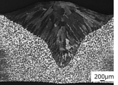
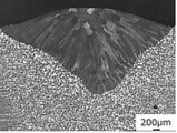
- FIG. 6 shows a cross-sectional photograph of a weld bead obtained from an aluminum alloy weld wire having the composition of Example 2. Further, an enlarged photograph of the apex of the welded portion in FIG. 6 is shown in FIG. Although a slight crack is generated at the apex of the weld, it can be seen that the expansion and propagation of the crack are suppressed even in the valest train test.
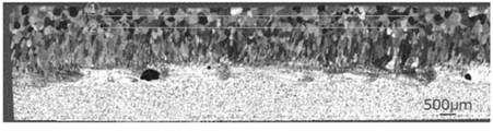
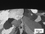
- FIG. 8 shows the microstructure (optical micrograph) of the weld bead obtained from the aluminum alloy weld wire having the composition of Example 3.
- FIG. 8 shows the observation result of the vertical cross section parallel to the longitudinal direction of the weld bead at the center of the weld bead width.
- Welded portions welded beads
- a structure consisting of columnar crystals is formed near the boundary between the aluminum alloy plate and the welded portion, and the vicinity of the surface of the welded portion is from equiaxed grains. It can be seen that the tissue is formed.
- the average particle size of the equiaxed grains near the surface of the joint was calculated by the intersection method and found to be 139 ⁇ m. More specifically, two 10 mm lines were drawn (shown in FIG. 8), and the intersections with the crystal grains were counted and calculated by "line length (20 mm) / number of intersections".
- Table 3 shows the crack rate in the weld bead and the amount of Sr in the center of the weld bead. It can be seen that a large amount of weld cracks are generated in the weld bead obtained in the comparative example as compared with the weld bead obtained in the example. Further, when a small amount of Sr is added (Comparative Example 2), the cracking rate is larger than when Sr is not added (Comparative Example 1). The result means that the suppression of welding cracks by the addition of Sr largely depends on the amount of Sr added.
- FIG. 12 shows the fine structure (optical micrograph) of the weld bead obtained from the aluminum alloy welding wire having the composition of Comparative Example 1.
- FIG. 12 shows the observation result of the vertical cross section parallel to the longitudinal direction of the weld bead at the center of the weld bead width. Similar to the weld beads obtained in the examples, a structure composed of columnar crystals and a structure composed of equiaxed grains are observed, but the proportion of the structure composed of columnar crystals is large.
- the average particle size of the equiaxed grains in the vicinity of the surface of the joint was calculated using the photograph shown in FIG. 12 in the same manner as in the example, it was 174 ⁇ m.
- the average particle size of the equiaxed grains in the welded portion obtained from the aluminum alloy welded wire having the composition of Example 3 is 139 ⁇ m, and the equiaxed grains in the vicinity of the surface of the joint are refined by the addition of Sr. I understand.
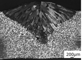
- FIG. 13 shows a cross-sectional photograph of a weld bead obtained with an aluminum alloy weld wire having the composition of Comparative Example 1. Further, as shown in FIG. 14, an enlarged photograph of the apex of the welded portion in FIG. 13 shows that a deep crack is formed at the apex of the welded portion. Since no cracks are observed in FIGS. 9 and 10 when the aluminum welded wire having the composition of Example 2 is used, the use of the aluminum alloy filler material of the present invention is extremely effective even in high-speed joining. It can be seen that welding cracks can be suppressed.
Landscapes
- Engineering & Computer Science (AREA)
- Mechanical Engineering (AREA)
- Physics & Mathematics (AREA)
- Optics & Photonics (AREA)
- Chemical & Material Sciences (AREA)
- Plasma & Fusion (AREA)
- Materials Engineering (AREA)
- Metallurgy (AREA)
- Organic Chemistry (AREA)
- Laser Beam Processing (AREA)
- Arc Welding In General (AREA)
Priority Applications (5)
| Application Number | Priority Date | Filing Date | Title |
|---|---|---|---|
| JP2022543334A JP7371789B2 (ja) | 2020-08-21 | 2021-07-21 | アルミニウム合金溶加材、アルミニウム合金製溶接構造体及びアルミニウム材の溶接方法 |
| CN202180051580.5A CN115989332B (zh) | 2020-08-21 | 2021-07-21 | 铝合金焊料、铝合金制焊接结构体以及铝材的焊接方法 |
| KR1020237009180A KR102850451B1 (ko) | 2020-08-21 | 2021-07-21 | 알루미늄 합금 용가재, 알루미늄 합금제 용접 구조체 및 알루미늄재의 용접 방법 |
| EP21858103.1A EP4202071A4 (en) | 2020-08-21 | 2021-07-21 | Aluminum alloy filler metal, aluminum alloy welded structure, and method for welding aluminum material |
| US18/019,955 US20230286083A1 (en) | 2020-08-21 | 2021-07-21 | Aluminum alloy filler metal, aluminum alloy welded structure, and method for welding aluminum material |
Applications Claiming Priority (2)
| Application Number | Priority Date | Filing Date | Title |
|---|---|---|---|
| JP2020139833 | 2020-08-21 | ||
| JP2020-139833 | 2020-08-21 |
Publications (1)
| Publication Number | Publication Date |
|---|---|
| WO2022038954A1 true WO2022038954A1 (ja) | 2022-02-24 |
Family
ID=80350352
Family Applications (1)
| Application Number | Title | Priority Date | Filing Date |
|---|---|---|---|
| PCT/JP2021/027264 Ceased WO2022038954A1 (ja) | 2020-08-21 | 2021-07-21 | アルミニウム合金溶加材、アルミニウム合金製溶接構造体及びアルミニウム材の溶接方法 |
Country Status (7)
| Country | Link |
|---|---|
| US (1) | US20230286083A1 (cg-RX-API-DMAC7.html) |
| EP (1) | EP4202071A4 (cg-RX-API-DMAC7.html) |
| JP (1) | JP7371789B2 (cg-RX-API-DMAC7.html) |
| KR (1) | KR102850451B1 (cg-RX-API-DMAC7.html) |
| CN (1) | CN115989332B (cg-RX-API-DMAC7.html) |
| TW (1) | TWI876079B (cg-RX-API-DMAC7.html) |
| WO (1) | WO2022038954A1 (cg-RX-API-DMAC7.html) |
Families Citing this family (1)
| Publication number | Priority date | Publication date | Assignee | Title |
|---|---|---|---|---|
| CN117086507A (zh) * | 2023-10-07 | 2023-11-21 | 湖南大学苏州研究院 | 一种低钪铝合金焊丝 |
Citations (6)
| Publication number | Priority date | Publication date | Assignee | Title |
|---|---|---|---|---|
| JPH01143792A (ja) * | 1987-11-30 | 1989-06-06 | Furukawa Alum Co Ltd | 成形金型用アルミニウム合金溶加材 |
| JPH05208296A (ja) * | 1992-01-30 | 1993-08-20 | Kobe Steel Ltd | 金型用アルミニウム合金溶加材 |
| JPH0847788A (ja) * | 1994-08-03 | 1996-02-20 | Sumitomo Heavy Ind Ltd | アルミニウム合金のyagレーザ溶接方法 |
| JP2006218491A (ja) | 2005-02-09 | 2006-08-24 | Nissan Motor Co Ltd | アルミニウム合金用溶接材料及び溶接方法 |
| JP2015093313A (ja) * | 2013-11-13 | 2015-05-18 | 近畿車輌株式会社 | アルミニウム押出形材の突合せ溶接接合方法及び鉄道車両用構体 |
| CN107081536A (zh) * | 2017-05-09 | 2017-08-22 | 安徽飞弧焊业股份有限公司 | 一种城轨列车用抗疲劳高韧性铝合金焊丝 |
Family Cites Families (16)
| Publication number | Priority date | Publication date | Assignee | Title |
|---|---|---|---|---|
| JPS60250893A (ja) * | 1984-05-25 | 1985-12-11 | Sumitomo Light Metal Ind Ltd | アルミニウム製熱交換器用アルミニウム合金ろう |
| JPH1143792A (ja) | 1997-07-23 | 1999-02-16 | Asahi Kagaku Kogyo Co Ltd | 酸洗促進剤、酸洗促進剤を含んだ酸洗液組成物およびこれを用いる酸洗方法 |
| US8758529B2 (en) * | 2010-06-30 | 2014-06-24 | GM Global Technology Operations LLC | Cast aluminum alloys |
| US20140308541A1 (en) * | 2011-12-02 | 2014-10-16 | Uacj Corporation | Bonded body of aluminum alloy and copper alloy, and bonding method for same |
| IN2014MN01665A (cg-RX-API-DMAC7.html) * | 2012-01-27 | 2015-05-29 | Uacj Corp | |
| JP5816317B2 (ja) * | 2014-03-28 | 2015-11-18 | 株式会社神戸製鋼所 | 電縫溶接用アルミニウム合金ブレージングシート |
| CN106794556A (zh) * | 2014-10-09 | 2017-05-31 | 株式会社Uacj | 铝合金钎焊板和硬钎焊方法 |
| JP6523681B2 (ja) * | 2014-12-25 | 2019-06-05 | 株式会社Uacj | ケース用アルミニウム合金板及びケース |
| CN104630576B (zh) * | 2014-12-29 | 2017-01-11 | 江苏中色锐毕利实业有限公司 | 一种导热性能优异的亚共晶铝硅合金及其制备方法与应用 |
| US10421159B2 (en) * | 2015-02-25 | 2019-09-24 | Hobart Brothers Llc | Systems and methods for additive manufacturing using aluminum metal-cored wire |
| JP6713861B2 (ja) * | 2015-07-08 | 2020-06-24 | 株式会社デンソー | アルミニウム合金クラッド材及びその製造方法、ならびに、当該アルミニウム合金クラッド材を用いた熱交換器 |
| JP2017018996A (ja) * | 2015-07-13 | 2017-01-26 | 株式会社Uacj | アルミニウム合金ブレージングシート |
| JP2017074610A (ja) * | 2015-10-16 | 2017-04-20 | 株式会社Uacj | アルミニウム合金ブレージングシート及びろう付け方法 |
| CN105331856B (zh) * | 2015-12-04 | 2018-05-22 | 江苏亨通电力特种导线有限公司 | 一种微合金化的Al-Si合金及其铝合金杆的制备方法 |
| US20190032175A1 (en) * | 2017-02-01 | 2019-01-31 | Hrl Laboratories, Llc | Aluminum alloys with grain refiners, and methods for making and using the same |
| CN110497115B (zh) * | 2018-05-16 | 2022-08-09 | 林肯环球股份有限公司 | 具有碱土金属的焊接电极焊丝 |
-
2021
- 2021-07-21 KR KR1020237009180A patent/KR102850451B1/ko active Active
- 2021-07-21 US US18/019,955 patent/US20230286083A1/en active Pending
- 2021-07-21 EP EP21858103.1A patent/EP4202071A4/en active Pending
- 2021-07-21 WO PCT/JP2021/027264 patent/WO2022038954A1/ja not_active Ceased
- 2021-07-21 JP JP2022543334A patent/JP7371789B2/ja active Active
- 2021-07-21 CN CN202180051580.5A patent/CN115989332B/zh active Active
- 2021-08-02 TW TW110128284A patent/TWI876079B/zh active
Patent Citations (6)
| Publication number | Priority date | Publication date | Assignee | Title |
|---|---|---|---|---|
| JPH01143792A (ja) * | 1987-11-30 | 1989-06-06 | Furukawa Alum Co Ltd | 成形金型用アルミニウム合金溶加材 |
| JPH05208296A (ja) * | 1992-01-30 | 1993-08-20 | Kobe Steel Ltd | 金型用アルミニウム合金溶加材 |
| JPH0847788A (ja) * | 1994-08-03 | 1996-02-20 | Sumitomo Heavy Ind Ltd | アルミニウム合金のyagレーザ溶接方法 |
| JP2006218491A (ja) | 2005-02-09 | 2006-08-24 | Nissan Motor Co Ltd | アルミニウム合金用溶接材料及び溶接方法 |
| JP2015093313A (ja) * | 2013-11-13 | 2015-05-18 | 近畿車輌株式会社 | アルミニウム押出形材の突合せ溶接接合方法及び鉄道車両用構体 |
| CN107081536A (zh) * | 2017-05-09 | 2017-08-22 | 安徽飞弧焊业股份有限公司 | 一种城轨列车用抗疲劳高韧性铝合金焊丝 |
Non-Patent Citations (1)
| Title |
|---|
| See also references of EP4202071A4 |
Also Published As
| Publication number | Publication date |
|---|---|
| JP7371789B2 (ja) | 2023-10-31 |
| EP4202071A4 (en) | 2024-01-24 |
| EP4202071A1 (en) | 2023-06-28 |
| US20230286083A1 (en) | 2023-09-14 |
| KR20230051690A (ko) | 2023-04-18 |
| CN115989332A (zh) | 2023-04-18 |
| KR102850451B1 (ko) | 2025-08-26 |
| JPWO2022038954A1 (cg-RX-API-DMAC7.html) | 2022-02-24 |
| CN115989332B (zh) | 2024-06-14 |
| TW202208645A (zh) | 2022-03-01 |
| TWI876079B (zh) | 2025-03-11 |
Similar Documents
| Publication | Publication Date | Title |
|---|---|---|
| JP4669903B2 (ja) | 二輪車およびバギー車用フレーム材 | |
| JP2010279982A (ja) | Al合金溶加材 | |
| TWI917557B (zh) | 熔接用鋁合金延展材、熔接接合體及鋁合金材的熔接方法 | |
| JP5431795B2 (ja) | Al材料の溶接方法 | |
| JP2013031878A (ja) | 隅肉溶接の溶接継手 | |
| JP4603399B2 (ja) | メタル系フラックス入りワイヤおよび溶接方法 | |
| JP7371789B2 (ja) | アルミニウム合金溶加材、アルミニウム合金製溶接構造体及びアルミニウム材の溶接方法 | |
| JP6847766B2 (ja) | アルミニウム合金溶加材、アルミニウム合金の溶接方法及びアルミニウム合金材 | |
| JP6632839B2 (ja) | アルミニウム合金溶加材及びアルミニウム合金の溶接方法 | |
| US20050220660A1 (en) | Al-Si based alloy and alloy member made therefrom | |
| JP5431797B2 (ja) | Al合金溶接継手 | |
| JP7327669B2 (ja) | 溶接用アルミニウム合金展伸材、アルミニウム合金溶接接合体及びその溶接方法 | |
| JP2017110272A (ja) | 高エネルギービーム溶接用Al合金材及びその製造方法 | |
| JP6619473B2 (ja) | アルミニウム合金溶加材の製造方法 | |
| CN118900925A (zh) | 铸件用Al-Si合金及Al-Si合金铸件以及Al-Si合金铸件接合体 | |
| JP6886861B2 (ja) | アルミニウム合金の溶接方法 | |
| JP2018149601A (ja) | Al−Mg系合金の溶接方法 | |
| JP6405145B2 (ja) | アルミニウム合金溶加材 | |
| JP6619474B2 (ja) | アルミニウム合金溶加材用ビレット及びその製造方法 | |
| JP6925189B2 (ja) | アルミニウム材の溶接接合体及びその製造方法 | |
| JP2017082254A (ja) | 高エネルギービーム溶接用Al合金材 | |
| JP2005034896A (ja) | アルミニウム合金溶接用溶加材及びそれを使用したアルミニウム合金材の溶接方法 |
Legal Events
| Date | Code | Title | Description |
|---|---|---|---|
| 121 | Ep: the epo has been informed by wipo that ep was designated in this application |
Ref document number: 21858103 Country of ref document: EP Kind code of ref document: A1 |
|
| ENP | Entry into the national phase |
Ref document number: 2022543334 Country of ref document: JP Kind code of ref document: A |
|
| ENP | Entry into the national phase |
Ref document number: 20237009180 Country of ref document: KR Kind code of ref document: A |
|
| NENP | Non-entry into the national phase |
Ref country code: DE |
|
| ENP | Entry into the national phase |
Ref document number: 2021858103 Country of ref document: EP Effective date: 20230321 |
|
| WWG | Wipo information: grant in national office |
Ref document number: 1020237009180 Country of ref document: KR |