WO2022030562A1 - 洗浄用スポンジローラ - Google Patents
洗浄用スポンジローラ Download PDFInfo
- Publication number
- WO2022030562A1 WO2022030562A1 PCT/JP2021/029016 JP2021029016W WO2022030562A1 WO 2022030562 A1 WO2022030562 A1 WO 2022030562A1 JP 2021029016 W JP2021029016 W JP 2021029016W WO 2022030562 A1 WO2022030562 A1 WO 2022030562A1
- Authority
- WO
- WIPO (PCT)
- Prior art keywords
- core
- sponge
- cleaning
- sponge body
- water
- Prior art date
- Legal status (The legal status is an assumption and is not a legal conclusion. Google has not performed a legal analysis and makes no representation as to the accuracy of the status listed.)
- Ceased
Links
Images








Classifications
-
- B—PERFORMING OPERATIONS; TRANSPORTING
- B08—CLEANING
- B08B—CLEANING IN GENERAL; PREVENTION OF FOULING IN GENERAL
- B08B1/00—Cleaning by methods involving the use of tools
- B08B1/10—Cleaning by methods involving the use of tools characterised by the type of cleaning tool
- B08B1/14—Wipes; Absorbent members, e.g. swabs or sponges
- B08B1/143—Wipes
-
- A—HUMAN NECESSITIES
- A46—BRUSHWARE
- A46B—BRUSHES
- A46B13/00—Brushes with driven brush bodies or carriers
- A46B13/02—Brushes with driven brush bodies or carriers power-driven carriers
-
- A—HUMAN NECESSITIES
- A46—BRUSHWARE
- A46B—BRUSHES
- A46B13/00—Brushes with driven brush bodies or carriers
- A46B13/001—Cylindrical or annular brush bodies
-
- A—HUMAN NECESSITIES
- A46—BRUSHWARE
- A46B—BRUSHES
- A46B9/00—Arrangements of the bristles in the brush body
- A46B9/005—Arrangements of the bristles in the brush body where the brushing material is not made of bristles, e.g. sponge, rubber or paper
-
- A—HUMAN NECESSITIES
- A47—FURNITURE; DOMESTIC ARTICLES OR APPLIANCES; COFFEE MILLS; SPICE MILLS; SUCTION CLEANERS IN GENERAL
- A47L—DOMESTIC WASHING OR CLEANING; SUCTION CLEANERS IN GENERAL
- A47L13/00—Implements for cleaning floors, carpets, furniture, walls, or wall coverings
- A47L13/10—Scrubbing; Scouring; Cleaning; Polishing
- A47L13/16—Cloths; Pads; Sponges
-
- B—PERFORMING OPERATIONS; TRANSPORTING
- B22—CASTING; POWDER METALLURGY
- B22F—WORKING METALLIC POWDER; MANUFACTURE OF ARTICLES FROM METALLIC POWDER; MAKING METALLIC POWDER; APPARATUS OR DEVICES SPECIALLY ADAPTED FOR METALLIC POWDER
- B22F3/00—Manufacture of workpieces or articles from metallic powder characterised by the manner of compacting or sintering; Apparatus specially adapted therefor ; Presses and furnaces
- B22F3/10—Sintering only
- B22F3/11—Making porous workpieces or articles
-
- H—ELECTRICITY
- H10—SEMICONDUCTOR DEVICES; ELECTRIC SOLID-STATE DEVICES NOT OTHERWISE PROVIDED FOR
- H10P—GENERIC PROCESSES OR APPARATUS FOR THE MANUFACTURE OR TREATMENT OF DEVICES COVERED BY CLASS H10
- H10P52/00—Grinding, lapping or polishing of wafers, substrates or parts of devices
-
- H—ELECTRICITY
- H10—SEMICONDUCTOR DEVICES; ELECTRIC SOLID-STATE DEVICES NOT OTHERWISE PROVIDED FOR
- H10P—GENERIC PROCESSES OR APPARATUS FOR THE MANUFACTURE OR TREATMENT OF DEVICES COVERED BY CLASS H10
- H10P72/00—Handling or holding of wafers, substrates or devices during manufacture or treatment thereof
- H10P72/04—Apparatus for manufacture or treatment
- H10P72/0402—Apparatus for fluid treatment
- H10P72/0406—Apparatus for fluid treatment for cleaning followed by drying, rinsing, stripping, blasting or the like
- H10P72/0411—Apparatus for fluid treatment for cleaning followed by drying, rinsing, stripping, blasting or the like for wet cleaning or washing
- H10P72/0412—Apparatus for fluid treatment for cleaning followed by drying, rinsing, stripping, blasting or the like for wet cleaning or washing using mainly scrubbing means, e.g. brushes
-
- A—HUMAN NECESSITIES
- A46—BRUSHWARE
- A46B—BRUSHES
- A46B11/00—Brushes with reservoir or other means for applying substances, e.g. paints, pastes, water
- A46B11/06—Brushes with reservoir or other means for applying substances, e.g. paints, pastes, water connected to supply pipe or to other external supply means
- A46B11/063—Brushes with reservoir or other means for applying substances, e.g. paints, pastes, water connected to supply pipe or to other external supply means by means of a supply pipe
Definitions
- the present invention relates to a sponge roller for cleaning.
- polishing In the manufacturing process of aluminum hard disks, glass disks, wafers, photomasks, liquid crystal glass substrates, etc., high precision using various abrasive grains such as silicon oxide, alumina, ceria, etc. is used to finish the surface to an extremely high precision surface. Polishing, so-called polishing, is performed. Abrasive grains and polishing debris adhere to the surface of the polished object, and in order to remove them, it is necessary to perform sufficient cleaning after the polishing process.
- Cleaning methods after polishing include ultrasonic cleaning and jet water flow, but in order to obtain a high cleaning effect and reduce damage to the substrate, an elastic porous body (for example, polyvinyl acetal-based porous material) is used. Scrub cleaning with a sponge body consisting of a body) is widely used. Further, as the cleaning liquid, not only DI water but also various chemicals suitable for each substrate such as acid, alkali and solvent are usually used. For example, as a cleaning liquid for a silicon wafer, a mixed liquid of ammonia water and hydrogen peroxide water, a mixed liquid of dilute hydrofluoric acid, hydrochloric acid and hydrogen peroxide water, and the like are known.
- the shape of the sponge body of the elastic porous body is various, and among them, the brush roller-shaped sponge body having a large number of protrusions on the outer peripheral surface of the cylinder is preferably used for scrub cleaning (cleaning step).
- a good cleaning effect can be obtained by continuously contacting the crown of the protrusion with the cleaning surface of the object to be cleaned while rotating the. Since the body to be cleaned contacts only the protrusions of the sponge body, the friction is smaller and the damage to the body to be cleaned is less than that of a flat sponge body without protrusions, or impurities can easily move between the protrusions together with the cleaning liquid. There is an advantage that it passes through and is removed from the object to be cleaned.
- a dedicated cleaning device corresponding to each substrate is usually used, and a sponge roller for cleaning is composed of a sponge body and a core.
- the core inserts the inner diameter portion of the sponge body and fixedly supports the inner peripheral surface of the sponge body. Both ends of the core are connected to the rotary drive unit of the cleaning device, and a sponge roller for cleaning is attached to the cleaning device, and the sponge body and the body to be cleaned (in the case of a sponge body having protrusions, the protrusion and the body to be cleaned) are separated. Rotate the sponge body together with the core in contact.
- a hollow cylindrical hard core having an inner hole extending in the axial direction has a plurality of small holes penetrating from the inner hole to the outer peripheral surface of the core.
- One end of the core is non-rotatably supported by the shaft support on the drive rotation side of the cleaning device, and the other end is non-rotatably supported by the shaft support on the driven rotation side of the cleaning device.
- One end of the inner hole is closed and the other end is open.
- the inner hole and the cleaning liquid supply path of the cleaning device communicate with each other.
- the cleaning liquid is introduced from the cleaning liquid supply path into the inner hole of the core, supplied from the inner hole to the inner peripheral surface of the sponge body through a plurality of small holes, passes through the continuous pores of the sponge body, and reaches the outer surface of the sponge body. leak.
- start-up cleaning is performed as a preparatory process before the actual scrub cleaning in order to improve the cleanliness of the sponge body itself.
- scrub cleaning is performed using a dummy wafer.
- a monitor wafer is used in the middle, the actual number of defects on the wafer is counted, and when it is confirmed that the number of defects is less than a certain number, the start-up is completed. ..
- the number of wafers to be processed (specified number of wafers) required for the number of defects on the wafer to be sufficiently reduced is confirmed in advance, and the start-up is completed when the cleaning of the specified number of wafers is completed.
- the amount of water flowing through the sponge body varies depending on the location even during scrub cleaning after the start-up is completed. (The amount of water flow becomes uneven). If the amount of water flow is non-uniform, the concentration of the chemical solution directly supplied from the sponge body onto the wafer becomes non-uniform, and there is a possibility that the entire area of the wafer cannot be washed evenly.
- an object of the present invention is to provide a cleaning sponge roller capable of suppressing variation in the amount of water flow.
- the cleaning sponge roller of the present invention includes a cylindrical sponge body and a shaft body-shaped core.
- the sponge body is composed of a porous material having continuous pores and having elasticity in a wet state.
- the core inserts the inner diameter portion of the sponge body and fixedly supports the inner peripheral surface of the sponge body.
- the core is composed of a porous sintered body having continuous pores.
- the core is composed of a porous sintered body having continuous pores
- the continuous pores of the sintered body are water (for example, washing water) from the inside of the core (sintered body) toward the outer peripheral surface. It becomes a passage (water passage). Therefore, compared to the case where a hole for water passage (water passage hole) is formed in a core having no continuous pores, the water passage can be arranged evenly and finely, and the water passage can be arranged evenly and finely in the sponge body. It is possible to suppress variations in the amount of water flow.
- the core is preferably made of an organic sintered body (resin sintered body, sintered plastic).
- organic sintered body unlike a metal sintered body (sintering metals), there is no concern about the influence of metal elution on cleaning, and workability and rigidity are higher than those of an inorganic sintered body (ceramics). Because it is also excellent.
- the shape of the sintered body may be either a column shape or a cylinder shape, but the cylinder shape is preferable in order to reduce the pressure loss during water flow.
- the cross-sectional shape of either the pillar shape or the tubular shape is not limited to a circle, and may be another shape (for example, a polygonal shape).
- the average pore diameter of the sintered body is preferably 5 ⁇ m to 800 ⁇ m, and the porosity is preferably 30% to 50%. This is because if the average pore diameter is small and the porosity is low, the pressure loss during water flow increases, and if the average pore diameter is large and the porosity is high, sufficient strength may not be secured.
- the sponge body may be fixed to the core by entering the continuous pores of the sintered body and integrating with the sintered body. Since the inner diameter side of the sponge body penetrates into the fine continuous pores of the sintered body and is continuously integrated with the core in a densely intricate state, a water passage hole is formed in the core having no continuous pores. The sponge body can be firmly fixed to the core as compared with the case where the sponge body enters the water passage hole.
- the entire inner diameter of the core is not filled with a sponge body, and a space (water flow space) that communicates in the axial direction is secured. Is preferable.
- a cleaning sponge roller (hereinafter referred to as a sponge roller) 1 according to an embodiment of the present invention will be described with reference to FIGS. 1 to 5.
- the sponge roller 1 includes a cylindrical sponge body 3 and a shaft body-shaped core (rotary shaft) 2.
- the sponge body 3 has a plurality of protrusions 5 protruding from the outer peripheral surface 4 at a substantially uniform density.
- Each protrusion 5 has a cylindrical shape and integrally projects from the base end portion on the outer peripheral surface 4 of the sponge body 3 toward the top portion (tip portion).
- the shape of the protrusion 5 is not limited to the cylindrical shape, and may be another shape. Further, the outer peripheral surface 4 of the sponge body 3 may not be provided with the protrusions 5 and may be a flat curved surface.
- the sponge body 3 is composed of a polyvinyl acetal-based porous material (PVAt-based porous material) having fine continuous pores and having elasticity in a water-containing state, for example.
- PVAt-based porous material polyvinyl acetal-based porous material
- the PVAt-based porous material cures in a dry state and softens in a wet state. Further, the PVAt-based porous material is excellent in water absorption and water retention, exhibits preferable flexibility and appropriate impact resilience when wet, and is also excellent in abrasion resistance.
- the core 2 is inserted through the inner diameter portion of the sponge body 3 to fixly support the inner peripheral surface of the sponge body 3.
- the core 2 of the present embodiment has a cylindrical shape as shown in FIG. 2, but the shape of the core 2 is not limited to the cylindrical shape, and other shapes (for example, a cylindrical shape having a polygonal cross section, a cylindrical shape, and a cross section) are used. May be a polygonal column shape, etc.).
- Core 2 is composed of a porous sintered body having continuous pores.
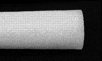
- FIG. 3 is a photograph of the outer peripheral surface of the end portion of the core 2, and it can be seen that the outer peripheral surface of the core 2 is finely uneven due to fine pores.
- the core 2 of the present embodiment is composed of an organic sintered body.
- the material (raw material) of the organic sintered body is not particularly limited, but for example, polypropylene, ultra-high density polyethylene, high-density polyethylene, low-density polyethylene, polymethacrylate, polystyrene, ethylene vinyl acetate, fluororesin, polyvinyl chloride, PEEK. (Polyetheretherketone resin) or the like can be used.
- the sponge body 3 of the present embodiment is fixed to the core 2 by entering the continuous pores of the sintered body and integrating with the sintered body.
- the sponge body 3 made of a PVAt-based porous material for example, one or more polyvinyl alcohols (raw materials) having an average degree of polymerization of 500 to 3000 and a saponification degree of 80% or more are mixed to form an aqueous solution, and this aqueous solution is used as a cross-linking agent.
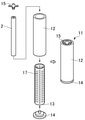
- Add aldehydes, mineral acids as a catalyst, starch as a pore-forming agent, etc. and inject a mixed solution of these into a predetermined mold 11 as shown in FIGS. 4 and 5, and react at 40 to 80 ° C. It is obtained by removing the pore-forming agent and the like by washing with water after taking it out of the mold 11.
- the mold 11 has an outer mold 12, an inner mold 13, a bottom plate 14, and a cap 15. Both the outer mold 12 and the inner mold 13 are formed in a cylindrical shape.
- the inner mold 13 has an outer diameter equal to or slightly smaller than the inner diameter of the outer mold 12, and is inserted into the outer mold 12.
- the core 2 is inserted approximately in the center of the inner mold 13.
- the bottom plate 14 closes the lower ends of the outer mold 12 and the inner mold 13 and supports the lower ends of the core 2.
- the cap 15 is fitted to the inner peripheral surface of the upper end of the outer mold 12.
- the core 2 is positioned by the bottom plate 14 and the cap 15.
- a substantially cylindrical space 16 for forming the sponge body 3 is partitioned between the inner peripheral surface of the inner mold 13 and the outer peripheral surface of the core 2.
- a plurality of through holes 17 for forming the protrusions 5 are formed in the inner mold 13, and each through hole 17 communicates with the space 16.
- the mixed liquid is injected into the space 16 from the casting nozzle 18 inserted between the outer mold 12 and the cap 15, and flows from the space 16 into each through hole 17.
- the air in the through hole 17 moves to the space 16 and is discharged from the upper end of the space 16 to the atmosphere. This ensures that the mixture is filled up to the end of the through hole 17.
- the sponge body 3 is taken out from the mold 11 together with the core 2 and washed with water. Since the core 2 is composed of a sintered body having continuous pores, the mixed liquid injected from the casting nozzle 18 flows through the continuous pores of the core 2 and is filled to the inner diameter portion of the core 2, and the sponge body 3 is filled. Is continuously formed from the outer peripheral surface of the core 2 to the inner diameter portion.
- the inner diameter side of the sponge body 3 enters the fine continuous pores of the sintered body and is continuously integrated with the core 2 in a densely intricate state, so that the sponge body 3 passes through the core having no continuous pores.
- the sponge body 3 can be firmly fixed to the core 2 as compared with the case where the water hole is formed and the sponge body enters the water passage hole.
- the sponge roller 1 can be suitably used for scrub cleaning.
- Scrub cleaning refers to chemical mechanical polishing (CMP) of the surface to be cleaned using a urethane pad or the like and a slurry-like abrasive, followed by particles mainly of the slurry-like abrasive from the surface to be cleaned. This is the process to remove it.
- CMP chemical mechanical polishing
- As the cleaning liquid pure water, an alkaline solution (for example, ammonia water) or an acidic solution (for example, dilute hydrofluoric acid) is used.
- one end and the other end of the core 2 are provided with a shaft support portion on the drive rotation side and a shaft support portion on the driven rotation side of the cleaning device (not shown). Support each of them so that they cannot rotate relative to each other.
- the inner diameter portion of the core 2 and the cleaning liquid supply path of the cleaning device communicate with each other.
- the cleaning liquid is introduced from the cleaning liquid supply path to the inner diameter portion of the core 2, is supplied from the inner diameter portion to the inner peripheral surface of the sponge body 3 through the continuous pores of the sintered body, passes through the continuous pores of the sponge body 3, and is sponge. It flows out to the outer surface of the body 3.
- the sponge non-supported region is used to prevent water leakage (outflow of cleaning liquid) from the outer peripheral surface of the sponge non-supported region.
- the outer peripheral surface of the seal member 6 may be covered with the seal member 6.
- the sealing member 6 includes a sheet material to be wrapped around the outer peripheral surface of the sintered body, a coating layer applied to the outer peripheral surface of the sintered body, and an annular member (axial direction of the sponge body 3) mounted on the outer peripheral surface of the sintered body. (Including flanges and the like that regulate movement and displacement in the longitudinal direction)).
- the average pore diameter of the sintered body is preferably 5 ⁇ m to 800 ⁇ m, and the porosity is preferably 30% to 50%. This is because if the average pore diameter is small and the porosity is low, the pressure loss during water flow increases, and if the average pore diameter is large and the porosity is high, sufficient strength may not be secured.
- the porosity is calculated by the following equation (1) from the apparent volume and true volume of the rectangular parallelepiped obtained by measuring the sintered body of the rectangular parallelepiped in a dry state sufficiently dried by the dryer with a dry automatic densitometer. Is the value to be.
- the average pore diameter is the average value of the diameters of a plurality of pores existing in the internal structure of the sintered body.
- the value of the average pore diameter specified in this embodiment is a value measured using a mercury porosimeter.
- a cylindrical or cylindrical shielding shaft 19 (see FIG. 5) that blocks the inflow of the mixed liquid from the inner peripheral surface of the core 2 to the inner diameter portion so that an excess sponge body is not generated in the inner diameter portion of the core 2.
- the mixed liquid may be cast with the core 2 inserted into the inner diameter portion of the core 2.
- the sponge body 3 is produced by injecting the mixed solution into the mold and reacting at 40 to 80 ° C., and after removing the sponge body 3 and the core 2 from the mold, the pore-forming material and the like are removed by washing with water to remove the pore-forming material and the like, and the inner diameter portion of the core 2 is formed.
- the surplus sponge body was excised to prepare a sponge roller 1.
- the core 2 is provided with a cylindrical (outer diameter 30 mm, inner diameter 18 mm, length 300 mm) polypropylene resin sintered body (porosity (pore diameter) 60 ⁇ m to 150 ⁇ m, porosity (porosity) 30% to 35%). Using.
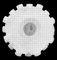
- FIG. 6 is a photograph of the end face of the sponge roller 1 after removing the excess sponge body from the inner diameter portion of the core 2. As shown in FIG. 6, it was confirmed that the sponge body entered the inside of the sintered body and the sponge body and the core were integrated to form a sponge roller.
- 80 discharge ports 23 (hole diameter 2.6 mm) having a hole shape communicating with the inner diameter portion are provided on the outer peripheral surface of a vinyl chloride pipe (outer diameter 32 mm, inner diameter 26 mm, length 300 mm).
- the sponge roller 21 was prepared by the same method as in the examples.
- the 80 discharge ports 23 were arranged at 4 locations (4 directions) by 90 ° in the circumferential direction and at 20 locations at equal intervals in the longitudinal direction (axial direction).
- a container for receiving the water flowing out from the outer peripheral surface of the sponge body 3 and falling was installed below the sponge body 3.
- the inside of the container was divided into 5 places (regions A to E shown in FIG. 1) at equal intervals in the longitudinal direction.
- the difference water amount difference between the maximum value (maximum amount) and the minimum value (minimum amount) of each water amount in each of the five areas A to E is measured.
- ) was calculated as an index of the variation in the amount of water flow due to the difference in the position in the axial direction, and the water flowability of the examples and the comparative examples was evaluated.
- the water amount difference was obtained for each of the cases where the amount of water supplied to the cores 2 and 22 (set water amount) was 250 mL / min, 500 mL / min, 1000 mL / min, 1500 mL / min, and 2000 mL / min, and the water amount difference was 50 mL or less.
- it was judged to be good ( ⁇ ) in the case of more than 50 mL and 100 mL or less, it was judged to be acceptable ( ⁇ ), and in the case of more than 100 mL, it was judged to be impossible ( ⁇ ).
- the results of the test are shown in FIG.
- the difference in water volume is 50 mL or less in any water volume
- the variation in water flow rate due to the difference in the axial position is small, and the variation in the water flow rate is small, and the sponge body 3 is uniformly from the outer peripheral surface in the axial direction (longitudinal direction). It turned out that water spilled.
- FIG. 9 shows a photograph of an embodiment
- FIG. 10 shows a photograph of a comparative example.
- Sponge rollers 1, 21 were attached to a scrub cleaning simulation device (not shown) and rotated at 800 rpm.
- the substrate (glass plate) 30 is sponge roller so that a larger force is applied between the sponge body 3 and the cores 2 and 22 at the start of rotation in order to easily confirm the presence or absence of twisting.
- the distance L1 from the axial center of one end of the cores 2 and 22 to the outer peripheral surface of the sponge body 3 is set from the axial center of the other end of the cores 2 and 22 to the outer peripheral surface of the sponge body 3.
- ⁇ indicates that no twist was generated, and ⁇ indicates that twist was generated.
- the twist occurred when the pushing amount was 2.5 mm or more.
- no twisting occurred at any pushing amount.
- the sponge rollers 1 and 21 are dropped from a predetermined height H to the floor surface in a posture in which the axes of the cores 2 and 22 stand up in the vertical direction, and the sponge body 3 and the cores 2 and 22 are dropped. It was confirmed whether or not there was a deviation (relative movement in the axial direction) from the initial state.
- the drop height H was set to 0.25 m and 0.5 m. The results of the test are shown in FIG.
- ⁇ indicates no deviation
- ⁇ indicates the occurrence of deviation.
- the deviation occurred in both cases, whereas in the examples, the deviation did not occur.
- the present invention is not limited to the above-mentioned embodiments, examples and variations thereof described as an example, and does not deviate from the technical idea of the present invention even if it is other than the above-mentioned embodiments and the like. Within the range, various changes can be made depending on the design and the like.
- the material of the sponge body 3 is not limited to the PVAt-based porous material, and may be any porous material having continuous pores and elasticity in a wet state.
- the present invention can be widely used as a cleaning sponge roller.
Landscapes
- Engineering & Computer Science (AREA)
- Manufacturing & Machinery (AREA)
- Mechanical Engineering (AREA)
- Cleaning Or Drying Semiconductors (AREA)
- Cleaning In General (AREA)
- Cleaning Implements For Floors, Carpets, Furniture, Walls, And The Like (AREA)
Priority Applications (3)
| Application Number | Priority Date | Filing Date | Title |
|---|---|---|---|
| CN202180058170.3A CN116171121A (zh) | 2020-08-07 | 2021-08-04 | 清洗用海绵辊 |
| KR1020237007863A KR20230048117A (ko) | 2020-08-07 | 2021-08-04 | 세정용 스펀지 롤러 |
| US18/040,777 US20230276931A1 (en) | 2020-08-07 | 2021-08-04 | Cleaning sponge roller |
Applications Claiming Priority (2)
| Application Number | Priority Date | Filing Date | Title |
|---|---|---|---|
| JP2020-134743 | 2020-08-07 | ||
| JP2020134743A JP7595907B2 (ja) | 2020-08-07 | 2020-08-07 | 洗浄用スポンジローラ |
Publications (1)
| Publication Number | Publication Date |
|---|---|
| WO2022030562A1 true WO2022030562A1 (ja) | 2022-02-10 |
Family
ID=80117547
Family Applications (1)
| Application Number | Title | Priority Date | Filing Date |
|---|---|---|---|
| PCT/JP2021/029016 Ceased WO2022030562A1 (ja) | 2020-08-07 | 2021-08-04 | 洗浄用スポンジローラ |
Country Status (6)
| Country | Link |
|---|---|
| US (1) | US20230276931A1 (https=) |
| JP (1) | JP7595907B2 (https=) |
| KR (1) | KR20230048117A (https=) |
| CN (1) | CN116171121A (https=) |
| TW (1) | TWI905244B (https=) |
| WO (1) | WO2022030562A1 (https=) |
Families Citing this family (4)
| Publication number | Priority date | Publication date | Assignee | Title |
|---|---|---|---|---|
| CN114734374A (zh) * | 2022-03-29 | 2022-07-12 | 北京国瑞升科技股份有限公司 | 用于清洁液晶面板的研磨辊及其制备方法 |
| TWI827446B (zh) * | 2023-01-16 | 2023-12-21 | 孫建忠 | 出水輪刷構造 |
| TWI875195B (zh) * | 2023-09-15 | 2025-03-01 | 碩晨生醫股份有限公司 | 刷輪結構 |
| CN117444820A (zh) * | 2023-11-23 | 2024-01-26 | 江西和美陶瓷有限公司 | 一种哑光抛釉瓷砖抛光装置及其方法 |
Citations (9)
| Publication number | Priority date | Publication date | Assignee | Title |
|---|---|---|---|---|
| JPS59197439A (ja) * | 1983-04-26 | 1984-11-09 | Asahi Chem Ind Co Ltd | 親水性多孔質焼結体 |
| JPH0751640A (ja) * | 1993-08-11 | 1995-02-28 | Inax Corp | タイルパネルの表面清掃方法 |
| US6070284A (en) * | 1998-02-04 | 2000-06-06 | Silikinetic Technology, Inc. | Wafer cleaning method and system |
| JP2002280344A (ja) * | 2001-03-16 | 2002-09-27 | Ebara Corp | 基板処理装置 |
| WO2005065849A1 (ja) * | 2003-12-26 | 2005-07-21 | Aion Co., Ltd. | 洗浄用スポンジローラー用の中芯 |
| WO2009147747A1 (ja) * | 2008-06-06 | 2009-12-10 | アイオン株式会社 | 洗浄用スポンジローラー用の中芯 |
| JP2011066386A (ja) * | 2009-08-20 | 2011-03-31 | Aion Kk | 洗浄用スポンジ体及び洗浄方法 |
| JP5032497B2 (ja) * | 2005-12-06 | 2012-09-26 | インテグリス・インコーポレーテッド | 多孔性パッド用の回転可能な成形ベース |
| JP6027101B2 (ja) * | 2011-06-08 | 2016-11-16 | イリノイ トゥール ワークス インコーポレイティド | Pvaスポンジブラシのブラシマンドレル |
Family Cites Families (10)
| Publication number | Priority date | Publication date | Assignee | Title |
|---|---|---|---|---|
| JPS5032497B1 (https=) | 1970-04-22 | 1975-10-21 | ||
| JPS6027101B2 (ja) | 1981-08-18 | 1985-06-27 | 松下電器産業株式会社 | 回転ヘッドアセンブリ− |
| AU7138198A (en) * | 1997-04-18 | 1998-11-13 | Cabot Corporation | Polishing pad for a semiconductor substrate |
| JP4965253B2 (ja) | 2003-08-08 | 2012-07-04 | インテグリス・インコーポレーテッド | 回転可能ベース上に鋳造されるモノリシック多孔性パッドを作製する方法および材料 |
| JP2006272134A (ja) * | 2005-03-29 | 2006-10-12 | Dainippon Screen Mfg Co Ltd | 基板処理装置 |
| JP2011196535A (ja) * | 2010-03-24 | 2011-10-06 | Toray Ind Inc | 多孔質プラスチックロールおよびその製造方法、ならびに多孔質プラスチックロールを用いたフィルム搬送装置 |
| JP2014045093A (ja) * | 2012-08-27 | 2014-03-13 | Sharp Corp | 基板搬送装置および基板処理装置 |
| JP2015196124A (ja) * | 2014-03-31 | 2015-11-09 | 株式会社荏原製作所 | ロールスポンジホルダー、ロールスポンジの製造方法、基板洗浄装置及び基板処理装置 |
| WO2016061432A1 (en) * | 2014-10-17 | 2016-04-21 | Porex Corporation | Disposable porous cleaning devices and methods |
| JP6966496B2 (ja) * | 2018-02-27 | 2021-11-17 | 国立大学法人埼玉大学 | バフ材及び研磨方法 |
-
2020
- 2020-08-07 JP JP2020134743A patent/JP7595907B2/ja active Active
-
2021
- 2021-08-04 CN CN202180058170.3A patent/CN116171121A/zh active Pending
- 2021-08-04 KR KR1020237007863A patent/KR20230048117A/ko active Pending
- 2021-08-04 WO PCT/JP2021/029016 patent/WO2022030562A1/ja not_active Ceased
- 2021-08-04 US US18/040,777 patent/US20230276931A1/en active Pending
- 2021-08-06 TW TW110129011A patent/TWI905244B/zh active
Patent Citations (9)
| Publication number | Priority date | Publication date | Assignee | Title |
|---|---|---|---|---|
| JPS59197439A (ja) * | 1983-04-26 | 1984-11-09 | Asahi Chem Ind Co Ltd | 親水性多孔質焼結体 |
| JPH0751640A (ja) * | 1993-08-11 | 1995-02-28 | Inax Corp | タイルパネルの表面清掃方法 |
| US6070284A (en) * | 1998-02-04 | 2000-06-06 | Silikinetic Technology, Inc. | Wafer cleaning method and system |
| JP2002280344A (ja) * | 2001-03-16 | 2002-09-27 | Ebara Corp | 基板処理装置 |
| WO2005065849A1 (ja) * | 2003-12-26 | 2005-07-21 | Aion Co., Ltd. | 洗浄用スポンジローラー用の中芯 |
| JP5032497B2 (ja) * | 2005-12-06 | 2012-09-26 | インテグリス・インコーポレーテッド | 多孔性パッド用の回転可能な成形ベース |
| WO2009147747A1 (ja) * | 2008-06-06 | 2009-12-10 | アイオン株式会社 | 洗浄用スポンジローラー用の中芯 |
| JP2011066386A (ja) * | 2009-08-20 | 2011-03-31 | Aion Kk | 洗浄用スポンジ体及び洗浄方法 |
| JP6027101B2 (ja) * | 2011-06-08 | 2016-11-16 | イリノイ トゥール ワークス インコーポレイティド | Pvaスポンジブラシのブラシマンドレル |
Also Published As
| Publication number | Publication date |
|---|---|
| TW202208107A (zh) | 2022-03-01 |
| CN116171121A (zh) | 2023-05-26 |
| KR20230048117A (ko) | 2023-04-10 |
| JP7595907B2 (ja) | 2024-12-09 |
| US20230276931A1 (en) | 2023-09-07 |
| JP2022030618A (ja) | 2022-02-18 |
| TWI905244B (zh) | 2025-11-21 |
Similar Documents
| Publication | Publication Date | Title |
|---|---|---|
| WO2022030562A1 (ja) | 洗浄用スポンジローラ | |
| US7955693B2 (en) | Foam composition roller brush with embedded mandrel | |
| TWI808227B (zh) | 基板清洗裝置及基板清洗方法 | |
| KR100281173B1 (ko) | 웨이퍼 연마장치 | |
| JP5155394B2 (ja) | 洗浄用スポンジローラ | |
| KR20070032934A (ko) | 회전식 기부 상에 주조된 일체형 다공성 패드를 제조하기위한 방법 및 재료 | |
| EP1188492B1 (en) | Cleaning sponge roller | |
| JP2022531472A (ja) | 一定の溝容積を有する化学機械平坦化パッド | |
| US6802877B2 (en) | Polyvinyl acetal composition roller brush with abrasive outer surface | |
| US7455575B2 (en) | Polishing pad cleaner and chemical mechanical polishing apparatus comprising the same | |
| JP2009117765A (ja) | 洗浄用スポンジローラ | |
| US20030200994A1 (en) | Pad for use in a critical environment | |
| JP3378015B2 (ja) | 洗浄用スポンジローラ | |
| JP6163081B2 (ja) | ブラシローラ | |
| US20040151890A1 (en) | Polyvinyl acetal composition skinless roller brush | |
| JP7708557B2 (ja) | 設計された開口空隙スペースを有する突出構造を有するcmp研磨パッド | |
| JP2004273530A (ja) | 洗浄装置およびその方法 | |
| JP4598325B2 (ja) | 基板用仮置台および基板の搬送方法 | |
| JP2004179414A (ja) | 研磨装置、研磨パッド、研磨液、膨潤処理液および研磨方法 | |
| JP2005305570A (ja) | 研磨パッド | |
| JP2004207397A (ja) | 研磨パッドおよび研磨装置 | |
| JP2006229100A (ja) | 研磨装置および半導体装置の製造方法 | |
| JP6088153B2 (ja) | ブラシローラ | |
| JP2003071711A (ja) | 基板用仮置台 |
Legal Events
| Date | Code | Title | Description |
|---|---|---|---|
| 121 | Ep: the epo has been informed by wipo that ep was designated in this application |
Ref document number: 21853534 Country of ref document: EP Kind code of ref document: A1 |
|
| ENP | Entry into the national phase |
Ref document number: 20237007863 Country of ref document: KR Kind code of ref document: A |
|
| WWE | Wipo information: entry into national phase |
Ref document number: 202317014849 Country of ref document: IN |
|
| NENP | Non-entry into the national phase |
Ref country code: DE |
|
| 122 | Ep: pct application non-entry in european phase |
Ref document number: 21853534 Country of ref document: EP Kind code of ref document: A1 |