WO2022030562A1 - 洗浄用スポンジローラ - Google Patents
洗浄用スポンジローラ Download PDFInfo
- Publication number
- WO2022030562A1 WO2022030562A1 PCT/JP2021/029016 JP2021029016W WO2022030562A1 WO 2022030562 A1 WO2022030562 A1 WO 2022030562A1 JP 2021029016 W JP2021029016 W JP 2021029016W WO 2022030562 A1 WO2022030562 A1 WO 2022030562A1
- Authority
- WO
- WIPO (PCT)
- Prior art keywords
- core
- sponge
- cleaning
- sponge body
- water
- Prior art date
Links
- 238000004140 cleaning Methods 0.000 title claims abstract description 67
- 239000011148 porous material Substances 0.000 claims abstract description 48
- 230000002093 peripheral effect Effects 0.000 claims description 35
- XLYOFNOQVPJJNP-UHFFFAOYSA-N water Substances O XLYOFNOQVPJJNP-UHFFFAOYSA-N 0.000 description 72
- 239000007788 liquid Substances 0.000 description 22
- 230000000052 comparative effect Effects 0.000 description 15
- 235000012431 wafers Nutrition 0.000 description 12
- 239000000463 material Substances 0.000 description 6
- 238000000034 method Methods 0.000 description 6
- 238000005498 polishing Methods 0.000 description 5
- 239000000758 substrate Substances 0.000 description 5
- KRHYYFGTRYWZRS-UHFFFAOYSA-N Fluorane Chemical compound F KRHYYFGTRYWZRS-UHFFFAOYSA-N 0.000 description 4
- 239000002253 acid Substances 0.000 description 3
- 239000007864 aqueous solution Substances 0.000 description 3
- 230000007547 defect Effects 0.000 description 3
- 239000011521 glass Substances 0.000 description 3
- 229910052751 metal Inorganic materials 0.000 description 3
- 239000002184 metal Substances 0.000 description 3
- -1 polypropylene Polymers 0.000 description 3
- 229920005989 resin Polymers 0.000 description 3
- 239000011347 resin Substances 0.000 description 3
- 239000000126 substance Substances 0.000 description 3
- 238000005406 washing Methods 0.000 description 3
- VHUUQVKOLVNVRT-UHFFFAOYSA-N Ammonium hydroxide Chemical compound [NH4+].[OH-] VHUUQVKOLVNVRT-UHFFFAOYSA-N 0.000 description 2
- VEXZGXHMUGYJMC-UHFFFAOYSA-N Hydrochloric acid Chemical compound Cl VEXZGXHMUGYJMC-UHFFFAOYSA-N 0.000 description 2
- 239000004696 Poly ether ether ketone Substances 0.000 description 2
- 239000004743 Polypropylene Substances 0.000 description 2
- 229920002472 Starch Polymers 0.000 description 2
- 239000006061 abrasive grain Substances 0.000 description 2
- DHKHKXVYLBGOIT-UHFFFAOYSA-N acetaldehyde Diethyl Acetal Natural products CCOC(C)OCC DHKHKXVYLBGOIT-UHFFFAOYSA-N 0.000 description 2
- 125000002777 acetyl group Chemical class [H]C([H])([H])C(*)=O 0.000 description 2
- 235000011114 ammonium hydroxide Nutrition 0.000 description 2
- 238000005266 casting Methods 0.000 description 2
- 239000003054 catalyst Substances 0.000 description 2
- 239000003795 chemical substances by application Substances 0.000 description 2
- 239000003431 cross linking reagent Substances 0.000 description 2
- 230000000694 effects Effects 0.000 description 2
- 125000002485 formyl group Chemical class [H]C(*)=O 0.000 description 2
- 229920001903 high density polyethylene Polymers 0.000 description 2
- 239000004700 high-density polyethylene Substances 0.000 description 2
- QOSATHPSBFQAML-UHFFFAOYSA-N hydrogen peroxide;hydrate Chemical compound O.OO QOSATHPSBFQAML-UHFFFAOYSA-N 0.000 description 2
- 238000004519 manufacturing process Methods 0.000 description 2
- 239000011259 mixed solution Substances 0.000 description 2
- 230000000149 penetrating effect Effects 0.000 description 2
- 230000035699 permeability Effects 0.000 description 2
- 229920002530 polyetherether ketone Polymers 0.000 description 2
- 229920001155 polypropylene Polymers 0.000 description 2
- 229920002451 polyvinyl alcohol Polymers 0.000 description 2
- 235000019422 polyvinyl alcohol Nutrition 0.000 description 2
- 239000002994 raw material Substances 0.000 description 2
- 239000008107 starch Substances 0.000 description 2
- 235000019698 starch Nutrition 0.000 description 2
- 229920002554 vinyl polymer Polymers 0.000 description 2
- 238000011041 water permeability test Methods 0.000 description 2
- JOYRKODLDBILNP-UHFFFAOYSA-N Ethyl urethane Chemical compound CCOC(N)=O JOYRKODLDBILNP-UHFFFAOYSA-N 0.000 description 1
- 239000004793 Polystyrene Substances 0.000 description 1
- 239000004372 Polyvinyl alcohol Substances 0.000 description 1
- VYPSYNLAJGMNEJ-UHFFFAOYSA-N Silicium dioxide Chemical compound O=[Si]=O VYPSYNLAJGMNEJ-UHFFFAOYSA-N 0.000 description 1
- XUIMIQQOPSSXEZ-UHFFFAOYSA-N Silicon Chemical compound [Si] XUIMIQQOPSSXEZ-UHFFFAOYSA-N 0.000 description 1
- BZHJMEDXRYGGRV-UHFFFAOYSA-N Vinyl chloride Chemical compound ClC=C BZHJMEDXRYGGRV-UHFFFAOYSA-N 0.000 description 1
- 238000005299 abrasion Methods 0.000 description 1
- 238000010521 absorption reaction Methods 0.000 description 1
- 239000003929 acidic solution Substances 0.000 description 1
- 150000007513 acids Chemical class 0.000 description 1
- 239000003513 alkali Substances 0.000 description 1
- 239000012670 alkaline solution Substances 0.000 description 1
- 229910052782 aluminium Inorganic materials 0.000 description 1
- XAGFODPZIPBFFR-UHFFFAOYSA-N aluminium Chemical compound [Al] XAGFODPZIPBFFR-UHFFFAOYSA-N 0.000 description 1
- PNEYBMLMFCGWSK-UHFFFAOYSA-N aluminium oxide Inorganic materials [O-2].[O-2].[O-2].[Al+3].[Al+3] PNEYBMLMFCGWSK-UHFFFAOYSA-N 0.000 description 1
- 239000012298 atmosphere Substances 0.000 description 1
- 239000002585 base Substances 0.000 description 1
- JUPQTSLXMOCDHR-UHFFFAOYSA-N benzene-1,4-diol;bis(4-fluorophenyl)methanone Chemical compound OC1=CC=C(O)C=C1.C1=CC(F)=CC=C1C(=O)C1=CC=C(F)C=C1 JUPQTSLXMOCDHR-UHFFFAOYSA-N 0.000 description 1
- DQXBYHZEEUGOBF-UHFFFAOYSA-N but-3-enoic acid;ethene Chemical compound C=C.OC(=O)CC=C DQXBYHZEEUGOBF-UHFFFAOYSA-N 0.000 description 1
- 239000000919 ceramic Substances 0.000 description 1
- CETPSERCERDGAM-UHFFFAOYSA-N ceric oxide Chemical compound O=[Ce]=O CETPSERCERDGAM-UHFFFAOYSA-N 0.000 description 1
- 229910000422 cerium(IV) oxide Inorganic materials 0.000 description 1
- 230000003749 cleanliness Effects 0.000 description 1
- 239000011247 coating layer Substances 0.000 description 1
- 238000011109 contamination Methods 0.000 description 1
- 238000006073 displacement reaction Methods 0.000 description 1
- 238000010828 elution Methods 0.000 description 1
- 238000005516 engineering process Methods 0.000 description 1
- 239000005038 ethylene vinyl acetate Substances 0.000 description 1
- 238000011086 high cleaning Methods 0.000 description 1
- 239000012535 impurity Substances 0.000 description 1
- 229910052500 inorganic mineral Inorganic materials 0.000 description 1
- 239000004973 liquid crystal related substance Substances 0.000 description 1
- 229920001684 low density polyethylene Polymers 0.000 description 1
- 239000004702 low-density polyethylene Substances 0.000 description 1
- QSHDDOUJBYECFT-UHFFFAOYSA-N mercury Chemical compound [Hg] QSHDDOUJBYECFT-UHFFFAOYSA-N 0.000 description 1
- 229910052753 mercury Inorganic materials 0.000 description 1
- 150000002739 metals Chemical class 0.000 description 1
- 239000011707 mineral Chemical class 0.000 description 1
- 239000000203 mixture Substances 0.000 description 1
- 238000000465 moulding Methods 0.000 description 1
- 239000003973 paint Substances 0.000 description 1
- 239000002245 particle Substances 0.000 description 1
- 229920003023 plastic Polymers 0.000 description 1
- 239000004033 plastic Substances 0.000 description 1
- 238000007517 polishing process Methods 0.000 description 1
- 229920001200 poly(ethylene-vinyl acetate) Polymers 0.000 description 1
- 238000006116 polymerization reaction Methods 0.000 description 1
- 229920000193 polymethacrylate Polymers 0.000 description 1
- 229920002223 polystyrene Polymers 0.000 description 1
- 229920000915 polyvinyl chloride Polymers 0.000 description 1
- 239000004800 polyvinyl chloride Substances 0.000 description 1
- 238000007127 saponification reaction Methods 0.000 description 1
- 238000005201 scrubbing Methods 0.000 description 1
- 238000007789 sealing Methods 0.000 description 1
- 229910052710 silicon Inorganic materials 0.000 description 1
- 239000010703 silicon Substances 0.000 description 1
- 229910052814 silicon oxide Inorganic materials 0.000 description 1
- 238000004088 simulation Methods 0.000 description 1
- 238000005245 sintering Methods 0.000 description 1
- 238000009751 slip forming Methods 0.000 description 1
- 239000000243 solution Substances 0.000 description 1
- 239000002904 solvent Substances 0.000 description 1
- 238000004506 ultrasonic cleaning Methods 0.000 description 1
Images


Classifications
-
- B08B1/143—
-
- A—HUMAN NECESSITIES
- A46—BRUSHWARE
- A46B—BRUSHES
- A46B13/00—Brushes with driven brush bodies or carriers
- A46B13/02—Brushes with driven brush bodies or carriers power-driven carriers
-
- A—HUMAN NECESSITIES
- A46—BRUSHWARE
- A46B—BRUSHES
- A46B13/00—Brushes with driven brush bodies or carriers
- A46B13/001—Cylindrical or annular brush bodies
-
- A—HUMAN NECESSITIES
- A46—BRUSHWARE
- A46B—BRUSHES
- A46B9/00—Arrangements of the bristles in the brush body
- A46B9/005—Arrangements of the bristles in the brush body where the brushing material is not made of bristles, e.g. sponge, rubber or paper
-
- A—HUMAN NECESSITIES
- A47—FURNITURE; DOMESTIC ARTICLES OR APPLIANCES; COFFEE MILLS; SPICE MILLS; SUCTION CLEANERS IN GENERAL
- A47L—DOMESTIC WASHING OR CLEANING; SUCTION CLEANERS IN GENERAL
- A47L13/00—Implements for cleaning floors, carpets, furniture, walls, or wall coverings
- A47L13/10—Scrubbing; Scouring; Cleaning; Polishing
- A47L13/16—Cloths; Pads; Sponges
-
- B—PERFORMING OPERATIONS; TRANSPORTING
- B22—CASTING; POWDER METALLURGY
- B22F—WORKING METALLIC POWDER; MANUFACTURE OF ARTICLES FROM METALLIC POWDER; MAKING METALLIC POWDER; APPARATUS OR DEVICES SPECIALLY ADAPTED FOR METALLIC POWDER
- B22F3/00—Manufacture of workpieces or articles from metallic powder characterised by the manner of compacting or sintering; Apparatus specially adapted therefor ; Presses and furnaces
- B22F3/10—Sintering only
- B22F3/11—Making porous workpieces or articles
-
- H—ELECTRICITY
- H01—ELECTRIC ELEMENTS
- H01L—SEMICONDUCTOR DEVICES NOT COVERED BY CLASS H10
- H01L21/00—Processes or apparatus adapted for the manufacture or treatment of semiconductor or solid state devices or of parts thereof
- H01L21/02—Manufacture or treatment of semiconductor devices or of parts thereof
- H01L21/04—Manufacture or treatment of semiconductor devices or of parts thereof the devices having at least one potential-jump barrier or surface barrier, e.g. PN junction, depletion layer or carrier concentration layer
- H01L21/18—Manufacture or treatment of semiconductor devices or of parts thereof the devices having at least one potential-jump barrier or surface barrier, e.g. PN junction, depletion layer or carrier concentration layer the devices having semiconductor bodies comprising elements of Group IV of the Periodic System or AIIIBV compounds with or without impurities, e.g. doping materials
- H01L21/30—Treatment of semiconductor bodies using processes or apparatus not provided for in groups H01L21/20 - H01L21/26
- H01L21/302—Treatment of semiconductor bodies using processes or apparatus not provided for in groups H01L21/20 - H01L21/26 to change their surface-physical characteristics or shape, e.g. etching, polishing, cutting
- H01L21/304—Mechanical treatment, e.g. grinding, polishing, cutting
-
- A—HUMAN NECESSITIES
- A46—BRUSHWARE
- A46B—BRUSHES
- A46B11/00—Brushes with reservoir or other means for applying substances, e.g. paints, pastes, water
- A46B11/06—Brushes with reservoir or other means for applying substances, e.g. paints, pastes, water connected to supply pipe or to other external supply means
- A46B11/063—Brushes with reservoir or other means for applying substances, e.g. paints, pastes, water connected to supply pipe or to other external supply means by means of a supply pipe
Definitions
- the present invention relates to a sponge roller for cleaning.
- polishing In the manufacturing process of aluminum hard disks, glass disks, wafers, photomasks, liquid crystal glass substrates, etc., high precision using various abrasive grains such as silicon oxide, alumina, ceria, etc. is used to finish the surface to an extremely high precision surface. Polishing, so-called polishing, is performed. Abrasive grains and polishing debris adhere to the surface of the polished object, and in order to remove them, it is necessary to perform sufficient cleaning after the polishing process.
- Cleaning methods after polishing include ultrasonic cleaning and jet water flow, but in order to obtain a high cleaning effect and reduce damage to the substrate, an elastic porous body (for example, polyvinyl acetal-based porous material) is used. Scrub cleaning with a sponge body consisting of a body) is widely used. Further, as the cleaning liquid, not only DI water but also various chemicals suitable for each substrate such as acid, alkali and solvent are usually used. For example, as a cleaning liquid for a silicon wafer, a mixed liquid of ammonia water and hydrogen peroxide water, a mixed liquid of dilute hydrofluoric acid, hydrochloric acid and hydrogen peroxide water, and the like are known.
- the shape of the sponge body of the elastic porous body is various, and among them, the brush roller-shaped sponge body having a large number of protrusions on the outer peripheral surface of the cylinder is preferably used for scrub cleaning (cleaning step).
- a good cleaning effect can be obtained by continuously contacting the crown of the protrusion with the cleaning surface of the object to be cleaned while rotating the. Since the body to be cleaned contacts only the protrusions of the sponge body, the friction is smaller and the damage to the body to be cleaned is less than that of a flat sponge body without protrusions, or impurities can easily move between the protrusions together with the cleaning liquid. There is an advantage that it passes through and is removed from the object to be cleaned.
- a dedicated cleaning device corresponding to each substrate is usually used, and a sponge roller for cleaning is composed of a sponge body and a core.
- the core inserts the inner diameter portion of the sponge body and fixedly supports the inner peripheral surface of the sponge body. Both ends of the core are connected to the rotary drive unit of the cleaning device, and a sponge roller for cleaning is attached to the cleaning device, and the sponge body and the body to be cleaned (in the case of a sponge body having protrusions, the protrusion and the body to be cleaned) are separated. Rotate the sponge body together with the core in contact.
- a hollow cylindrical hard core having an inner hole extending in the axial direction has a plurality of small holes penetrating from the inner hole to the outer peripheral surface of the core.
- One end of the core is non-rotatably supported by the shaft support on the drive rotation side of the cleaning device, and the other end is non-rotatably supported by the shaft support on the driven rotation side of the cleaning device.
- One end of the inner hole is closed and the other end is open.
- the inner hole and the cleaning liquid supply path of the cleaning device communicate with each other.
- the cleaning liquid is introduced from the cleaning liquid supply path into the inner hole of the core, supplied from the inner hole to the inner peripheral surface of the sponge body through a plurality of small holes, passes through the continuous pores of the sponge body, and reaches the outer surface of the sponge body. leak.
- start-up cleaning is performed as a preparatory process before the actual scrub cleaning in order to improve the cleanliness of the sponge body itself.
- scrub cleaning is performed using a dummy wafer.
- a monitor wafer is used in the middle, the actual number of defects on the wafer is counted, and when it is confirmed that the number of defects is less than a certain number, the start-up is completed. ..
- the number of wafers to be processed (specified number of wafers) required for the number of defects on the wafer to be sufficiently reduced is confirmed in advance, and the start-up is completed when the cleaning of the specified number of wafers is completed.
- the amount of water flowing through the sponge body varies depending on the location even during scrub cleaning after the start-up is completed. (The amount of water flow becomes uneven). If the amount of water flow is non-uniform, the concentration of the chemical solution directly supplied from the sponge body onto the wafer becomes non-uniform, and there is a possibility that the entire area of the wafer cannot be washed evenly.
- an object of the present invention is to provide a cleaning sponge roller capable of suppressing variation in the amount of water flow.
- the cleaning sponge roller of the present invention includes a cylindrical sponge body and a shaft body-shaped core.
- the sponge body is composed of a porous material having continuous pores and having elasticity in a wet state.
- the core inserts the inner diameter portion of the sponge body and fixedly supports the inner peripheral surface of the sponge body.
- the core is composed of a porous sintered body having continuous pores.
- the core is composed of a porous sintered body having continuous pores
- the continuous pores of the sintered body are water (for example, washing water) from the inside of the core (sintered body) toward the outer peripheral surface. It becomes a passage (water passage). Therefore, compared to the case where a hole for water passage (water passage hole) is formed in a core having no continuous pores, the water passage can be arranged evenly and finely, and the water passage can be arranged evenly and finely in the sponge body. It is possible to suppress variations in the amount of water flow.
- the core is preferably made of an organic sintered body (resin sintered body, sintered plastic).
- organic sintered body unlike a metal sintered body (sintering metals), there is no concern about the influence of metal elution on cleaning, and workability and rigidity are higher than those of an inorganic sintered body (ceramics). Because it is also excellent.
- the shape of the sintered body may be either a column shape or a cylinder shape, but the cylinder shape is preferable in order to reduce the pressure loss during water flow.
- the cross-sectional shape of either the pillar shape or the tubular shape is not limited to a circle, and may be another shape (for example, a polygonal shape).
- the average pore diameter of the sintered body is preferably 5 ⁇ m to 800 ⁇ m, and the porosity is preferably 30% to 50%. This is because if the average pore diameter is small and the porosity is low, the pressure loss during water flow increases, and if the average pore diameter is large and the porosity is high, sufficient strength may not be secured.
- the sponge body may be fixed to the core by entering the continuous pores of the sintered body and integrating with the sintered body. Since the inner diameter side of the sponge body penetrates into the fine continuous pores of the sintered body and is continuously integrated with the core in a densely intricate state, a water passage hole is formed in the core having no continuous pores. The sponge body can be firmly fixed to the core as compared with the case where the sponge body enters the water passage hole.
- the entire inner diameter of the core is not filled with a sponge body, and a space (water flow space) that communicates in the axial direction is secured. Is preferable.
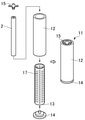
- a cleaning sponge roller (hereinafter referred to as a sponge roller) 1 according to an embodiment of the present invention will be described with reference to FIGS. 1 to 5.
- the sponge roller 1 includes a cylindrical sponge body 3 and a shaft body-shaped core (rotary shaft) 2.
- the sponge body 3 has a plurality of protrusions 5 protruding from the outer peripheral surface 4 at a substantially uniform density.
- Each protrusion 5 has a cylindrical shape and integrally projects from the base end portion on the outer peripheral surface 4 of the sponge body 3 toward the top portion (tip portion).
- the shape of the protrusion 5 is not limited to the cylindrical shape, and may be another shape. Further, the outer peripheral surface 4 of the sponge body 3 may not be provided with the protrusions 5 and may be a flat curved surface.
- the sponge body 3 is composed of a polyvinyl acetal-based porous material (PVAt-based porous material) having fine continuous pores and having elasticity in a water-containing state, for example.
- PVAt-based porous material polyvinyl acetal-based porous material
- the PVAt-based porous material cures in a dry state and softens in a wet state. Further, the PVAt-based porous material is excellent in water absorption and water retention, exhibits preferable flexibility and appropriate impact resilience when wet, and is also excellent in abrasion resistance.
- the core 2 is inserted through the inner diameter portion of the sponge body 3 to fixly support the inner peripheral surface of the sponge body 3.
- the core 2 of the present embodiment has a cylindrical shape as shown in FIG. 2, but the shape of the core 2 is not limited to the cylindrical shape, and other shapes (for example, a cylindrical shape having a polygonal cross section, a cylindrical shape, and a cross section) are used. May be a polygonal column shape, etc.).
- Core 2 is composed of a porous sintered body having continuous pores.
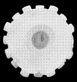
- FIG. 3 is a photograph of the outer peripheral surface of the end portion of the core 2, and it can be seen that the outer peripheral surface of the core 2 is finely uneven due to fine pores.
- the core 2 of the present embodiment is composed of an organic sintered body.
- the material (raw material) of the organic sintered body is not particularly limited, but for example, polypropylene, ultra-high density polyethylene, high-density polyethylene, low-density polyethylene, polymethacrylate, polystyrene, ethylene vinyl acetate, fluororesin, polyvinyl chloride, PEEK. (Polyetheretherketone resin) or the like can be used.
- the sponge body 3 of the present embodiment is fixed to the core 2 by entering the continuous pores of the sintered body and integrating with the sintered body.
- the sponge body 3 made of a PVAt-based porous material for example, one or more polyvinyl alcohols (raw materials) having an average degree of polymerization of 500 to 3000 and a saponification degree of 80% or more are mixed to form an aqueous solution, and this aqueous solution is used as a cross-linking agent.
- Add aldehydes, mineral acids as a catalyst, starch as a pore-forming agent, etc. and inject a mixed solution of these into a predetermined mold 11 as shown in FIGS. 4 and 5, and react at 40 to 80 ° C. It is obtained by removing the pore-forming agent and the like by washing with water after taking it out of the mold 11.
- the mold 11 has an outer mold 12, an inner mold 13, a bottom plate 14, and a cap 15. Both the outer mold 12 and the inner mold 13 are formed in a cylindrical shape.
- the inner mold 13 has an outer diameter equal to or slightly smaller than the inner diameter of the outer mold 12, and is inserted into the outer mold 12.
- the core 2 is inserted approximately in the center of the inner mold 13.
- the bottom plate 14 closes the lower ends of the outer mold 12 and the inner mold 13 and supports the lower ends of the core 2.
- the cap 15 is fitted to the inner peripheral surface of the upper end of the outer mold 12.
- the core 2 is positioned by the bottom plate 14 and the cap 15.
- a substantially cylindrical space 16 for forming the sponge body 3 is partitioned between the inner peripheral surface of the inner mold 13 and the outer peripheral surface of the core 2.
- a plurality of through holes 17 for forming the protrusions 5 are formed in the inner mold 13, and each through hole 17 communicates with the space 16.
- the mixed liquid is injected into the space 16 from the casting nozzle 18 inserted between the outer mold 12 and the cap 15, and flows from the space 16 into each through hole 17.
- the air in the through hole 17 moves to the space 16 and is discharged from the upper end of the space 16 to the atmosphere. This ensures that the mixture is filled up to the end of the through hole 17.
- the sponge body 3 is taken out from the mold 11 together with the core 2 and washed with water. Since the core 2 is composed of a sintered body having continuous pores, the mixed liquid injected from the casting nozzle 18 flows through the continuous pores of the core 2 and is filled to the inner diameter portion of the core 2, and the sponge body 3 is filled. Is continuously formed from the outer peripheral surface of the core 2 to the inner diameter portion.
- the inner diameter side of the sponge body 3 enters the fine continuous pores of the sintered body and is continuously integrated with the core 2 in a densely intricate state, so that the sponge body 3 passes through the core having no continuous pores.
- the sponge body 3 can be firmly fixed to the core 2 as compared with the case where the water hole is formed and the sponge body enters the water passage hole.
- the sponge roller 1 can be suitably used for scrub cleaning.
- Scrub cleaning refers to chemical mechanical polishing (CMP) of the surface to be cleaned using a urethane pad or the like and a slurry-like abrasive, followed by particles mainly of the slurry-like abrasive from the surface to be cleaned. This is the process to remove it.
- CMP chemical mechanical polishing
- As the cleaning liquid pure water, an alkaline solution (for example, ammonia water) or an acidic solution (for example, dilute hydrofluoric acid) is used.
- one end and the other end of the core 2 are provided with a shaft support portion on the drive rotation side and a shaft support portion on the driven rotation side of the cleaning device (not shown). Support each of them so that they cannot rotate relative to each other.
- the inner diameter portion of the core 2 and the cleaning liquid supply path of the cleaning device communicate with each other.
- the cleaning liquid is introduced from the cleaning liquid supply path to the inner diameter portion of the core 2, is supplied from the inner diameter portion to the inner peripheral surface of the sponge body 3 through the continuous pores of the sintered body, passes through the continuous pores of the sponge body 3, and is sponge. It flows out to the outer surface of the body 3.
- the sponge non-supported region is used to prevent water leakage (outflow of cleaning liquid) from the outer peripheral surface of the sponge non-supported region.
- the outer peripheral surface of the seal member 6 may be covered with the seal member 6.
- the sealing member 6 includes a sheet material to be wrapped around the outer peripheral surface of the sintered body, a coating layer applied to the outer peripheral surface of the sintered body, and an annular member (axial direction of the sponge body 3) mounted on the outer peripheral surface of the sintered body. (Including flanges and the like that regulate movement and displacement in the longitudinal direction)).
- the average pore diameter of the sintered body is preferably 5 ⁇ m to 800 ⁇ m, and the porosity is preferably 30% to 50%. This is because if the average pore diameter is small and the porosity is low, the pressure loss during water flow increases, and if the average pore diameter is large and the porosity is high, sufficient strength may not be secured.
- the porosity is calculated by the following equation (1) from the apparent volume and true volume of the rectangular parallelepiped obtained by measuring the sintered body of the rectangular parallelepiped in a dry state sufficiently dried by the dryer with a dry automatic densitometer. Is the value to be.
- the average pore diameter is the average value of the diameters of a plurality of pores existing in the internal structure of the sintered body.
- the value of the average pore diameter specified in this embodiment is a value measured using a mercury porosimeter.
- a cylindrical or cylindrical shielding shaft 19 (see FIG. 5) that blocks the inflow of the mixed liquid from the inner peripheral surface of the core 2 to the inner diameter portion so that an excess sponge body is not generated in the inner diameter portion of the core 2.
- the mixed liquid may be cast with the core 2 inserted into the inner diameter portion of the core 2.
- the sponge body 3 is produced by injecting the mixed solution into the mold and reacting at 40 to 80 ° C., and after removing the sponge body 3 and the core 2 from the mold, the pore-forming material and the like are removed by washing with water to remove the pore-forming material and the like, and the inner diameter portion of the core 2 is formed.
- the surplus sponge body was excised to prepare a sponge roller 1.
- the core 2 is provided with a cylindrical (outer diameter 30 mm, inner diameter 18 mm, length 300 mm) polypropylene resin sintered body (porosity (pore diameter) 60 ⁇ m to 150 ⁇ m, porosity (porosity) 30% to 35%). Using.
- FIG. 6 is a photograph of the end face of the sponge roller 1 after removing the excess sponge body from the inner diameter portion of the core 2. As shown in FIG. 6, it was confirmed that the sponge body entered the inside of the sintered body and the sponge body and the core were integrated to form a sponge roller.
- 80 discharge ports 23 (hole diameter 2.6 mm) having a hole shape communicating with the inner diameter portion are provided on the outer peripheral surface of a vinyl chloride pipe (outer diameter 32 mm, inner diameter 26 mm, length 300 mm).
- the sponge roller 21 was prepared by the same method as in the examples.
- the 80 discharge ports 23 were arranged at 4 locations (4 directions) by 90 ° in the circumferential direction and at 20 locations at equal intervals in the longitudinal direction (axial direction).
- a container for receiving the water flowing out from the outer peripheral surface of the sponge body 3 and falling was installed below the sponge body 3.
- the inside of the container was divided into 5 places (regions A to E shown in FIG. 1) at equal intervals in the longitudinal direction.
- the difference water amount difference between the maximum value (maximum amount) and the minimum value (minimum amount) of each water amount in each of the five areas A to E is measured.
- ) was calculated as an index of the variation in the amount of water flow due to the difference in the position in the axial direction, and the water flowability of the examples and the comparative examples was evaluated.
- the water amount difference was obtained for each of the cases where the amount of water supplied to the cores 2 and 22 (set water amount) was 250 mL / min, 500 mL / min, 1000 mL / min, 1500 mL / min, and 2000 mL / min, and the water amount difference was 50 mL or less.
- it was judged to be good ( ⁇ ) in the case of more than 50 mL and 100 mL or less, it was judged to be acceptable ( ⁇ ), and in the case of more than 100 mL, it was judged to be impossible ( ⁇ ).
- the results of the test are shown in FIG.
- the difference in water volume is 50 mL or less in any water volume
- the variation in water flow rate due to the difference in the axial position is small, and the variation in the water flow rate is small, and the sponge body 3 is uniformly from the outer peripheral surface in the axial direction (longitudinal direction). It turned out that water spilled.
- FIG. 9 shows a photograph of an embodiment
- FIG. 10 shows a photograph of a comparative example.
- Sponge rollers 1, 21 were attached to a scrub cleaning simulation device (not shown) and rotated at 800 rpm.
- the substrate (glass plate) 30 is sponge roller so that a larger force is applied between the sponge body 3 and the cores 2 and 22 at the start of rotation in order to easily confirm the presence or absence of twisting.
- the distance L1 from the axial center of one end of the cores 2 and 22 to the outer peripheral surface of the sponge body 3 is set from the axial center of the other end of the cores 2 and 22 to the outer peripheral surface of the sponge body 3.
- ⁇ indicates that no twist was generated, and ⁇ indicates that twist was generated.
- the twist occurred when the pushing amount was 2.5 mm or more.
- no twisting occurred at any pushing amount.
- the sponge rollers 1 and 21 are dropped from a predetermined height H to the floor surface in a posture in which the axes of the cores 2 and 22 stand up in the vertical direction, and the sponge body 3 and the cores 2 and 22 are dropped. It was confirmed whether or not there was a deviation (relative movement in the axial direction) from the initial state.
- the drop height H was set to 0.25 m and 0.5 m. The results of the test are shown in FIG.
- ⁇ indicates no deviation
- ⁇ indicates the occurrence of deviation.
- the deviation occurred in both cases, whereas in the examples, the deviation did not occur.
- the present invention is not limited to the above-mentioned embodiments, examples and variations thereof described as an example, and does not deviate from the technical idea of the present invention even if it is other than the above-mentioned embodiments and the like. Within the range, various changes can be made depending on the design and the like.
- the material of the sponge body 3 is not limited to the PVAt-based porous material, and may be any porous material having continuous pores and elasticity in a wet state.
- the present invention can be widely used as a cleaning sponge roller.
Abstract
洗浄用スポンジローラ1は、円筒状のスポンジ体3と軸体状のコア2とを備える。スポンジ体3は、連続気孔を有し、湿潤状態で弾性を有する多孔質材によって構成される。コア2は、スポンジ体3の内径部を挿通し、スポンジ体3の内周面を固定的に支持する。コア2は、連続気孔を有する多孔質の焼結体によって構成される。
Description
本発明は、洗浄用スポンジローラに関する。
アルミハードディスク、ガラスディスク、ウエハ、フォトマスク、或いは液晶ガラス基板等の製造工程では、その表面を極めて精度の高い面に仕上るために、酸化ケイ素、アルミナ、セリア等の各種砥粒を用いた高精度研磨、いわゆるポリッシング加工が行われる。ポリッシング加工された被研磨物の表面には、砥粒や研磨屑が付着しており、これらを除去するために、ポリッシング加工後に十分な洗浄を施す必要がある。
ポリッシング加工後の洗浄方法としては、超音波洗浄やジェット水流を用いる方法があるが、高い洗浄効果を得るため、また基板へのダメージを低減するため、弾性多孔質体(例えばポリビニルアセタール系多孔質体)からなるスポンジ体によるスクラブ洗浄が広く用いられている。また、洗浄液としては、通常DI水だけでなく、酸、アルカリ、溶剤といった各基板に適した各種薬剤も使用される。例えば、シリコンウエハの洗浄液としては、アンモニア水と過酸化水素水の混合液、希フッ酸、塩酸と過酸化水素水の混合液等が知られている。
弾性多孔質体のスポンジ体の形状は多様であるが、その中でも円筒の外周面に多数の突起を有するブラシローラ形状のスポンジ体がスクラブ洗浄(洗浄工程)に好適に用いられており、スポンジ体を回転させながら、その突起の頭頂部を被洗浄体の洗浄面に連続的に接触させることで、良好な洗浄効果が得られる。被洗浄体がスポンジ体の突起のみと接触するため、突起を有さないフラットなスポンジ体に比べて、摩擦が小さく被洗浄体へのダメージが少ない、或いは洗浄液とともに夾雑物が突起の間を容易に通過して被洗浄体から除去されるといった利点がある。
洗浄工程では、通常それぞれの基板に対応した専用の洗浄装置が使用され、スポンジ体とコアとによって洗浄用スポンジローラが構成される。コアはスポンジ体の内径部を挿通し、スポンジ体の内周面を固定的に支持する。コアの両端部を洗浄装置の回転駆動部に接続して洗浄用スポンジローラを洗浄装置に装着し、スポンジ体と被洗浄体(突起を有するスポンジ体の場合には突起と被洗浄体)とを接触させた状態でコアとともにスポンジ体を回転させる。
被洗浄体或いはスポンジ体にその上部や側面から洗浄液をノズル等で供給する装置もあるが、より洗浄能力を高めるために、コア内部からスポンジ体の内側に洗浄液を供給することも実施されている。
コア内部からスポンジ体の内側(内周面)に洗浄液を供給する技術として、軸方向に延びる内孔を有する中空円筒状の硬質のコアに、内孔からコア外周面に貫通する複数の小孔を設ける技術が公知である。コアの一端部は、洗浄装置の駆動回転側の軸支持部に相対回転不能に支持され、他端部は、洗浄装置の従動回転側の軸支持部に相対回転不能に支持される。内孔の一端は閉じており、他端は開いている。従動回転側の軸支持部に支持されるコアの他端部では、内孔と洗浄装置の洗浄液供給路とが連通する。洗浄液は、洗浄液供給路からコアの内孔へ導入され、内孔から複数の小孔を介してスポンジ体の内周面に供給され、スポンジ体の連続気孔を通過してスポンジ体の外表面に流出する。
洗浄用スポンジローラを洗浄装置に装着して最初に使用する際には、スポンジ体自身の清浄度を高めるため、実際のスクラブ洗浄を行う前の準備工程として立ち上げ洗浄が行われる。具体的には、スポンジ体を洗浄装置に装着した後、ダミーウエハを使用してスクラブ洗浄を行う。立ち上げ洗浄では、例えば、途中でモニター用ウエハを使用し、ウエハ上の実際のディフェクト数を計数し、ディフェクト数が一定個数以下になっていることが確認された場合に、立ち上げを完了する。或いは、ウエハ上のディフェクト数が十分に減少するまでに要するウエハの処理枚数(規定枚数)を事前に確認しておき、規定枚数のウエハの洗浄を完了した時点で立ち上げを完了する。
しかし、内孔からコア外周面に貫通する複数の小孔を設けた従来のコアの場合、コアからスポンジ体へ通水する吐出口(小孔)の場所と個数が固定されるため、立ち上げ洗浄が完了しても、スポンジ体に実際には水が通過していない領域が存在し、その後の使用によって未通過の領域を水が通過することでウエハの汚染の原因となる可能性がある。すなわち、コアから水が吐出する場所が特定の位置(小孔の位置)に限定されるので、スポンジ体内の状態にバラつきが生じる可能性がある。
また、スポンジ体へ通水する吐出口(小孔)の場所と個数が固定された上記従来のコアでは、立ち上げ完了後のスクラブ洗浄時においても、場所によってスポンジ体の通水量のバラツキが生じる(通水量が不均一になる)可能性がある。通水量が不均一であると、スポンジ体からウエハ上に直接供給される薬液の濃度が不均一になり、ウエハの全域を均等に洗浄することができない可能性が生じる。
そこで本発明は、通水量のバラツキを抑制することが可能な洗浄用スポンジローラの提供を目的とする。
上記目的を達成すべく、本発明の洗浄用スポンジローラは、円筒状のスポンジ体と軸体状のコアとを備える。スポンジ体は、連続気孔を有し、湿潤状態で弾性を有する多孔質材によって構成される。コアは、スポンジ体の内径部を挿通し、スポンジ体の内周面を固定的に支持する。コアは、連続気孔を有する多孔質の焼結体によって構成される。
上記構成では、連続気孔を有する多孔質の焼結体によってコアを構成しているので、焼結体の連続気孔がコア(焼結体)の内側から外周面に向かう水(例えば洗浄水)の通路(通水路)となる。このため、連続気孔を有さないコアに通水用の孔(通水孔)を形成する場合に比べて、通水路をムラなく均一に且つ細密に配設することができ、スポンジ体内での通水量のバラツキを抑制することができる。
上記コアは、有機焼結体(樹脂焼結体、焼結体プラスチック)によって構成することが好適である。有機焼結体の場合、金属焼結体(シンタリングメタルス)のように金属の溶出による洗浄への影響が懸念されることがなく、また、加工性及び剛性が無機焼結体(セラミックス)よりも優れているためである。
焼結体の形状は、柱形状及び筒形状の何れでもよいが、通水時の圧損を低減するためには筒形状が好適である。なお、柱形状及び筒形状の何れにおいても、その断面形状は、円形に限定されず、他の形状(例えば多角形状等)であってもよい。
焼結体の平均気孔径は5μm~800μmが好適であり、気孔率は30%~50%が好適である。平均気孔径が小さく気孔率が低いと通水時の圧損が増大し、平均気孔径が大きく気孔率が高いと十分な強度が確保できない可能性があるためである。
スポンジ体は、焼結体の連続気孔へ入り込んで焼結体と一体化することによりコアに固定されてもよい。スポンジ体の内径側は、焼結体の微細な連続気孔へ入り込み、緻密に入組んだ状態で連続してコアと一体化するので、連続気孔を有さないコアに通水孔を形成し、通水孔にスポンジ体が入り込む場合に比べて、スポンジ体をコアに強固に固定することができる。
また、筒状のコアを用いる場合、通水時の圧損の増大を抑制するため、コアの内径部の全域にスポンジ体を充填せず、軸方向に連通する空間(通水空間)を確保することが好ましい。
本発明によれば、通水量のバラツキを抑制することができる。
本発明の一実施形態に係る洗浄用スポンジローラ(以下スポンジローラと称する)1について、図1~図5を参照して説明する。
図1に示すように、スポンジローラ1は、円筒形状のスポンジ体3と、軸体状のコア(回転軸)2とを備える。
スポンジ体3は、外周面4から略均一な密度で突出する複数の突起5を有する。各突起5は、円柱形状であり、スポンジ体3の外周面4上の基端部から頂部(先端部)に向かって一体的に突出する。突起5の形状は、円柱形状に限定されず、他の形状であってもよい。また、スポンジ体3の外周面4に突起5を設けず、平坦な湾曲面としてもよい。
スポンジ体3は、微細な連続気孔を有し、例えば含水状態で弾性を有するポリビニルアセタール系多孔質素材(PVAt系多孔質素材)から構成される。PVAt系多孔質素材は、乾燥状態で硬化し、湿潤状態で軟化する。また、PVAt系多孔質素材は、吸水性及び保水性に優れ、湿潤時に好ましい柔軟性と適度な反発弾性を示し、耐磨耗性にも優れている。
コア2は、スポンジ体3の内径部を挿通し、スポンジ体3の内周面を固定的に支持する。本実施形態のコア2は、図2に示すように円筒形状であるが、コア2の形状は円筒形状に限定されず、他の形状(例えば、断面が多角形の筒形状、円柱形状、断面が多角形の柱形状等)であってもよい。
コア2は、連続気孔を有する多孔質の焼結体によって構成される。図3はコア2の端部の外周面の写真であり、微細な気孔によりコア2の外周面が細かく凹凸していることが判る。本実施形態のコア2は、有機焼結体によって構成される。有機焼結体の素材(原料)は特に限定されないが、例えば、ポリプロピレン、超高密度ポリエチレン、高密度ポリエチレン、低密度ポリエチレン、ポリメタアクリレート、ポリスチレン、エチレン酢酸ビニル、フッ素樹脂、ポリ塩化ビニル、PEEK(ポリエーテルエーテルケトン樹脂)などを用いることができる。
本実施形態のスポンジ体3は、焼結体の連続気孔へ入り込んで焼結体と一体化することによりコア2に固定される。PVAt系多孔質素材から成るスポンジ体3の場合、例えば平均重合度500~3000でケン化度80%以上のポリビニルアルコール(原料)を一種又はそれ以上混合して水溶液とし、この水溶液に架橋剤としてアルデヒド類、触媒として鉱酸類、及び気孔形成剤として澱粉等を加え、これらの混合液を、図4及び図5に示すような所定の型11内に注入し、40~80℃で反応させて型11から取り出した後、水洗により気孔形成剤等を除去することによって得られる。
型11は、外型12と内型13と底板14とキャップ15とを有する。外型12及び内型13は、共に円筒状に形成されている。内型13は、外型12の内径と同一か又はそれよりも僅かに小さい外径を有し、外型12内に挿入される。コア2は、内型13のほぼ中心に挿入される。底板14は、外型12及び内型13の下端を塞ぐと共に、コア2の下端を支持する。キャップ15は、外型12の上端の内周面に嵌合される。コア2は、底板14とキャップ15とによって位置決めされる。
内型13の内周面とコア2の外周面との間には、スポンジ体3を形成するための略円筒状の空間16が区画される。内型13には、突起5を形成するための貫通孔17が複数形成され、各貫通孔17は空間16と連通する。混合液は、外型12とキャップ15との間に挿入された注型ノズル18から空間16へ注入され、空間16から各貫通孔17へ流入する。同時に、貫通孔17内の空気は、空間16へ移動し、空間16の上端から大気へ放出される。これにより、混合液が貫通孔17の末端まで確実に充填される。
スポンジ体3は、コア2とともに型11から取り出されて水洗される。コア2が連続気孔を有する焼結体によって構成されているため、注型ノズル18から注入された混合液は、コア2の連続気孔を流通してコア2の内径部まで充填され、スポンジ体3は、コア2の外周面から内径部へ連続して形成される。
このように、スポンジ体3の内径側は、焼結体の微細な連続気孔へ入り込み、緻密に入組んだ状態で連続してコア2と一体化するので、連続気孔を有さないコアに通水孔を形成し、通水孔にスポンジ体が入り込む場合に比べて、スポンジ体3をコア2に強固に固定することができる。
スポンジローラ1は、スクラブ洗浄に好適に用いることができる。スクラブ洗浄とは、ウレタンパッド等とスラリー状の研磨剤とを用いた被洗浄面の化学機械研磨(CMP:Chemical Mechanical Polishing)の後に、スラリー状の研磨剤を中心とするパーティクルを被洗浄面から除去するために行う処理である。洗浄液としては、純水やアルカリ性溶液(例えばアンモニア水)や酸性溶液(例えば希フッ酸)が用いられる。
図1に示すスポンジローラ1によってスクラブ洗浄を行う場合、例えばコア2の一端部と他端部とを、洗浄装置(図示省略)の駆動回転側の軸支持部と従動回転側の軸支持部とにそれぞれ相対回転不能に支持する。従動回転側の軸支持部に支持されるコア2の他端部では、コア2の内径部と洗浄装置の洗浄液供給路とが連通する。洗浄液は、洗浄液供給路からコア2の内径部へ導入され、内径部から焼結体の連続気孔を介してスポンジ体3の内周面に供給され、スポンジ体3の連続気孔を通過してスポンジ体3の外表面に流出する。
コア2にスポンジ体3と重ならないスポンジ非支持領域(図1の例では両端部)が存在する場合、スポンジ非支持領域の外周面からの漏水(洗浄液の流出)を防ぐため、スポンジ非支持領域の外周面をシール部材6によって被覆してもよい。シール部材6は、焼結体の外周面に巻き付けるシート材や、焼結体の外周面に塗布される被覆層の他、焼結体の外周に装着される環状部材(スポンジ体3の軸方向(長手方向)の移動や変位を規制するフランジ等を含む)であってもよい。
焼結体の平均気孔径は5μm~800μmが好適であり、気孔率は30%~50%が好適である。平均気孔径が小さく気孔率が低いと通水時の圧損が増大し、平均気孔径が大きく気孔率が高いと十分な強度が確保できない可能性があるためである。
上記気孔率とは、乾燥機で十分に乾燥された乾燥状態の直方体の焼結体を乾式自動密度計にて測定し、直方体の見掛け体積と真体積とから、次式(1)にて算出される値である。
気孔率(%)=(見掛け体積-真体積)/見掛け体積×100…(1)
上記平均気孔径は、焼結体の内部組織に存在する複数の気孔の径の平均値である。本実施形態で規定する平均気孔径の値は、水銀ポロシメーターを用いて測定した値である。
洗浄装置からコア2の内径部へ洗浄水(洗浄液)を供給する通水時において、圧損の増大を抑制するため、コア2の内径部にスポンジ体3を充填せず、軸方向に連通する空間(通水空間)を確保することが好ましい。このため、本実施形態では、スポンジ体3の生成時にコア2の内径部へ侵入した余剰のスポンジ体を、スポンジ体3の生成後に切除している。なお、コア2の内径部に余剰のスポンジ体が生成されないように、コア2の内周面から内径部への混合液の流入を阻止する円柱状又は円筒状の遮蔽軸19(図5参照)をコア2の内径部に挿入した状態で混合液の注型を行ってもよい。
次に、本発明の実施例を比較例と対比して説明する。
(実施例)
ポリビニルアルコールを水溶液とし、この水溶液に架橋剤としてアルデヒド類、触媒として酸、及び気孔径形成材として澱粉等を加えた混合液とし、図4及び図5に示すようにコア2を付加した型11に混合液を注入し40~80℃で反応させてスポンジ体3を生成し、スポンジ体3及びコア2を型から取り出した後、水洗により気孔形成材などを除去し、コア2の内径部の余剰のスポンジ体を切除して、スポンジローラ1を作製した。
ポリビニルアルコールを水溶液とし、この水溶液に架橋剤としてアルデヒド類、触媒として酸、及び気孔径形成材として澱粉等を加えた混合液とし、図4及び図5に示すようにコア2を付加した型11に混合液を注入し40~80℃で反応させてスポンジ体3を生成し、スポンジ体3及びコア2を型から取り出した後、水洗により気孔形成材などを除去し、コア2の内径部の余剰のスポンジ体を切除して、スポンジローラ1を作製した。
コア2には、円筒形状(外径30mm、内径18mm、長さ300mm)のポリプロピレン樹脂焼結体(気孔径(空孔径)60μm~150μm、気孔率(空孔率)30%~35%)を用いた。
図6は、コア2の内径部から余剰のスポンジ体を切除した後のスポンジローラ1の端面の写真である。図6に示すように、スポンジ体が焼結体の内部に入り込み、スポンジ体とコアが一体となってスポンジローラが形成されていることが確認された。
(比較例)
図7に示すように、塩化ビニル製のパイプ(外径32mm、内径26mm、長さ300mm)の外周面に、内径部と連通する孔形状の80個の吐出口23(孔径2.6mm)を形成したコア22を使用し、実施例と同様の方法によってスポンジローラ21を作成した。80個の吐出口23は、円周方向には90°ずつ4箇所(4方向)に、長手方向(軸方向)には等間隔に20箇所に配置した。
図7に示すように、塩化ビニル製のパイプ(外径32mm、内径26mm、長さ300mm)の外周面に、内径部と連通する孔形状の80個の吐出口23(孔径2.6mm)を形成したコア22を使用し、実施例と同様の方法によってスポンジローラ21を作成した。80個の吐出口23は、円周方向には90°ずつ4箇所(4方向)に、長手方向(軸方向)には等間隔に20箇所に配置した。
(通水性試験)
コア2,22の一端面からコア2,22の内径部へ水を供給し、供給した水がコア2,22の内径部からスポンジ体3へ通水してスポンジ体3の外周面から流出する様子を、実施例のスポンジローラ1及び比較例のスポンジローラ21についてそれぞれ観察して評価した。
コア2,22の一端面からコア2,22の内径部へ水を供給し、供給した水がコア2,22の内径部からスポンジ体3へ通水してスポンジ体3の外周面から流出する様子を、実施例のスポンジローラ1及び比較例のスポンジローラ21についてそれぞれ観察して評価した。
通水性を評価するため、スポンジ体3の外周面から流出して落下する水を受ける容器を、スポンジ体3の下方に設置した。容器の内部を、長手方向に等間隔に5箇所(図1に示すA~Eの領域)に区分した。各領域A~Eにおいて、1分間に流下して溜まる水量を測定し、5箇所の領域A~Eの各水量のうち最大値(最大量)と最小値(最小量)との差(水量差)を、軸方向の位置の相違による通水量のバラツキの指標として算出し、実施例及び比較例の通水性を評価した。
試験では、コア2,22へ供給する水量(設定水量)が250mL/min、500mL/min、1000mL/min、1500mL/min、及び2000mL/minの各場合について水量差を求め、水量差が50mL以下の場合は良(○)、50mLを超えて100mL以下の場合は可(△)、100mLを超えている場合は不可(×)と判定した。試験の結果を図8に示す。
図8に示すように、比較例では、1分間あたりの設定水量が1000mL及び1500mLの場合、最大量と最小量との差(水量差)が100mL以下であったが、それ以外の水量では100mLを超えており、判定結果は不可であった。特に、少ない水量(250mL/min及び500mL/min)において、軸方向の位置の相違による通水量のバラツキが大きいことが判った。
これに対し実施例では、何れの水量においても水量差が50mL以下であり、軸方向の位置の相違による通水量のバラツキが小さく、軸方向(長手方向)で均一にスポンジ体3の外周面から水が流出することが判った。
また、通水の初期段階でスポンジ体3の外周面から水が流出する様子を、蛍光性の液体(蛍光塗料を混ぜた水)を供給することにより観察し、実施例と比較例とを比較した。実施例の様子を撮影した写真を図9に、比較例の様子を撮影した写真を図10にそれぞれ示す。図9及び図10において、色が濃い領域ほど通水量が少なく、色が薄くなるに従って通水量が多くなる。従って、濃淡の差が小さいほど通水量のバラツキが小さいことになる。
比較例では、図10に示すように、スポンジ体の軸方向の中央付近から水が多く流出していることが判る。これに対し実施例では、図9に示すように、スポンジ体の軸方向の全域から均一に水が流出していることが判る。
(耐久試験(1))
スポンジ体3に外力を付加し、捩れ(コア2,22に対するスポンジ体3の回転方向の移動)の発生の有無を実施例及び比較例について確認した。
スポンジ体3に外力を付加し、捩れ(コア2,22に対するスポンジ体3の回転方向の移動)の発生の有無を実施例及び比較例について確認した。
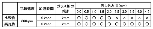
スポンジローラ1,21(コア2,22)をスクラブ洗浄の模擬装置(図示省略)に取付け、800rpmで回転させた。捩れの発生の有無を確認し易くするため、回転開始時にスポンジ体3とコア2,22との間により大きな力が加わるように、図11に示すように、基板(ガラス板)30をスポンジローラ1,21に対して斜めに配置(コア2,22の一端の軸心からスポンジ体3の外周面までの距離L1を、コア2,22の他端の軸心からスポンジ体3の外周面までの距離L2よりも2mm短く設定)し、回転数が800rpmに到達するまでの時間をモーターの下限値である0.2秒に設定し、押し込み量を変更しながら捩れの発生の有無を確認した。押し込み量は、0mm(略無負荷で接触)から4.5mmまで、0.5mmずつ増加した。試験の結果を図12に示す。
図12において、○は捩れの発生なし、×は捩れの発生ありを示す。通常の使用時よりも過度に力を加えた条件下において、比較例では押し込み量2.5mm以降で捩れが発生した。一方、実施例では何れの押込み量においても捩れが発生しなかった。
(耐久試験(2))
スポンジ体3に外力を付加し、コア2,22に対するスポンジ体3の軸方向の移動の発生の有無を実施例及び比較例について確認した。
スポンジ体3に外力を付加し、コア2,22に対するスポンジ体3の軸方向の移動の発生の有無を実施例及び比較例について確認した。
図13に示すように、コア2,22の軸心が鉛直方向に沿って起立する姿勢でスポンジローラ1,21を所定の高さHから床面に落下させ、スポンジ体3とコア2,22との間に初期状態からのズレ(軸方向の相対移動)が発生するか否かを確認した。落下高さHは、0.25mと0.5mに設定した。試験の結果を図14に示す。
図14において、○はズレの発生なし、×はズレの発生ありを示す。比較例では0.25m及び0.5mの高さから落下させた場合、双方ともズレが発生したのに対し、実施例では何れもズレが発生しなかった。
以上の試験の結果から、実施例のスポンジローラ1の方が比較例のスポンジローラ21よりも通水性及び耐久性に優れていることが確認された。
なお、本発明は、一例として説明した上述の実施形態、実施例及びその変形例に限定されることはなく、上述の実施形態等以外であっても、本発明に係る技術的思想を逸脱しない範囲であれば、設計等に応じて種々の変更が可能である。
例えば、スポンジ体3の素材はPVAt系多孔質素材に限定されず、連続気孔を有し、湿潤状態で弾性を有する多孔質素材であればよい。
本発明は、洗浄用スポンジローラとして広く用いることができる。
1,21:洗浄用スポンジローラ
2,22:コア
3:スポンジ体
4:スポンジ体の外周面
5:スポンジ体の突起
2,22:コア
3:スポンジ体
4:スポンジ体の外周面
5:スポンジ体の突起
Claims (5)
- 連続気孔を有し、湿潤状態で弾性を有する多孔質材によって構成された円筒状のスポンジ体と、
前記スポンジ体の内径部を挿通し、前記スポンジ体の内周面を固定的に支持する軸体状のコアと、を備え、
前記コアを、連続気孔を有する多孔質の焼結体によって構成した
ことを特徴とする洗浄用スポンジローラのコア。 - 前記コアを、有機焼結体によって構成した
ことを特徴とする請求項1に記載の洗浄用スポンジローラ。 - 前記焼結体が筒形状である
ことを特徴とする請求項1又は請求項2に記載の洗浄用スポンジローラ。 - 前記焼結体の平均気孔径が5μm~800μmであり、気孔率が30%~50%である
ことを特徴とする請求項1~請求項3の何れか1項に記載の洗浄用スポンジローラ。 - 前記スポンジ体は、前記焼結体の連続気孔へ入り込んで前記焼結体と一体化することにより前記コアに固定される
ことを特徴とする請求項1~請求項3の何れか1項に記載の洗浄用スポンジローラ。
Priority Applications (3)
| Application Number | Priority Date | Filing Date | Title |
|---|---|---|---|
| CN202180058170.3A CN116171121A (zh) | 2020-08-07 | 2021-08-04 | 清洗用海绵辊 |
| US18/040,777 US20230276931A1 (en) | 2020-08-07 | 2021-08-04 | Cleaning sponge roller |
| KR1020237007863A KR20230048117A (ko) | 2020-08-07 | 2021-08-04 | 세정용 스펀지 롤러 |
Applications Claiming Priority (2)
| Application Number | Priority Date | Filing Date | Title |
|---|---|---|---|
| JP2020-134743 | 2020-08-07 | ||
| JP2020134743A JP2022030618A (ja) | 2020-08-07 | 2020-08-07 | 洗浄用スポンジローラ |
Publications (1)
| Publication Number | Publication Date |
|---|---|
| WO2022030562A1 true WO2022030562A1 (ja) | 2022-02-10 |
Family
ID=80117547
Family Applications (1)
| Application Number | Title | Priority Date | Filing Date |
|---|---|---|---|
| PCT/JP2021/029016 WO2022030562A1 (ja) | 2020-08-07 | 2021-08-04 | 洗浄用スポンジローラ |
Country Status (6)
| Country | Link |
|---|---|
| US (1) | US20230276931A1 (ja) |
| JP (1) | JP2022030618A (ja) |
| KR (1) | KR20230048117A (ja) |
| CN (1) | CN116171121A (ja) |
| TW (1) | TW202208107A (ja) |
| WO (1) | WO2022030562A1 (ja) |
Families Citing this family (1)
| Publication number | Priority date | Publication date | Assignee | Title |
|---|---|---|---|---|
| TWI827446B (zh) * | 2023-01-16 | 2023-12-21 | 孫建忠 | 出水輪刷構造 |
Citations (9)
| Publication number | Priority date | Publication date | Assignee | Title |
|---|---|---|---|---|
| JPS59197439A (ja) * | 1983-04-26 | 1984-11-09 | Asahi Chem Ind Co Ltd | 親水性多孔質焼結体 |
| JPH0751640A (ja) * | 1993-08-11 | 1995-02-28 | Inax Corp | タイルパネルの表面清掃方法 |
| US6070284A (en) * | 1998-02-04 | 2000-06-06 | Silikinetic Technology, Inc. | Wafer cleaning method and system |
| JP2002280344A (ja) * | 2001-03-16 | 2002-09-27 | Ebara Corp | 基板処理装置 |
| WO2005065849A1 (ja) * | 2003-12-26 | 2005-07-21 | Aion Co., Ltd. | 洗浄用スポンジローラー用の中芯 |
| WO2009147747A1 (ja) * | 2008-06-06 | 2009-12-10 | アイオン株式会社 | 洗浄用スポンジローラー用の中芯 |
| JP2011066386A (ja) * | 2009-08-20 | 2011-03-31 | Aion Kk | 洗浄用スポンジ体及び洗浄方法 |
| JP5032497B2 (ja) * | 2005-12-06 | 2012-09-26 | インテグリス・インコーポレーテッド | 多孔性パッド用の回転可能な成形ベース |
| JP6027101B2 (ja) * | 2011-06-08 | 2016-11-16 | イリノイ トゥール ワークス インコーポレイティド | Pvaスポンジブラシのブラシマンドレル |
Family Cites Families (3)
| Publication number | Priority date | Publication date | Assignee | Title |
|---|---|---|---|---|
| JPS5032497B1 (ja) | 1970-04-22 | 1975-10-21 | ||
| JPS6027101B2 (ja) | 1981-08-18 | 1985-06-27 | 松下電器産業株式会社 | 回転ヘッドアセンブリ− |
| US7984526B2 (en) | 2003-08-08 | 2011-07-26 | Entegris, Inc. | Methods and materials for making a monolithic porous pad cast onto a rotatable base |
-
2020
- 2020-08-07 JP JP2020134743A patent/JP2022030618A/ja active Pending
-
2021
- 2021-08-04 KR KR1020237007863A patent/KR20230048117A/ko unknown
- 2021-08-04 WO PCT/JP2021/029016 patent/WO2022030562A1/ja active Application Filing
- 2021-08-04 CN CN202180058170.3A patent/CN116171121A/zh active Pending
- 2021-08-04 US US18/040,777 patent/US20230276931A1/en active Pending
- 2021-08-06 TW TW110129011A patent/TW202208107A/zh unknown
Patent Citations (9)
| Publication number | Priority date | Publication date | Assignee | Title |
|---|---|---|---|---|
| JPS59197439A (ja) * | 1983-04-26 | 1984-11-09 | Asahi Chem Ind Co Ltd | 親水性多孔質焼結体 |
| JPH0751640A (ja) * | 1993-08-11 | 1995-02-28 | Inax Corp | タイルパネルの表面清掃方法 |
| US6070284A (en) * | 1998-02-04 | 2000-06-06 | Silikinetic Technology, Inc. | Wafer cleaning method and system |
| JP2002280344A (ja) * | 2001-03-16 | 2002-09-27 | Ebara Corp | 基板処理装置 |
| WO2005065849A1 (ja) * | 2003-12-26 | 2005-07-21 | Aion Co., Ltd. | 洗浄用スポンジローラー用の中芯 |
| JP5032497B2 (ja) * | 2005-12-06 | 2012-09-26 | インテグリス・インコーポレーテッド | 多孔性パッド用の回転可能な成形ベース |
| WO2009147747A1 (ja) * | 2008-06-06 | 2009-12-10 | アイオン株式会社 | 洗浄用スポンジローラー用の中芯 |
| JP2011066386A (ja) * | 2009-08-20 | 2011-03-31 | Aion Kk | 洗浄用スポンジ体及び洗浄方法 |
| JP6027101B2 (ja) * | 2011-06-08 | 2016-11-16 | イリノイ トゥール ワークス インコーポレイティド | Pvaスポンジブラシのブラシマンドレル |
Also Published As
| Publication number | Publication date |
|---|---|
| JP2022030618A (ja) | 2022-02-18 |
| CN116171121A (zh) | 2023-05-26 |
| US20230276931A1 (en) | 2023-09-07 |
| TW202208107A (zh) | 2022-03-01 |
| KR20230048117A (ko) | 2023-04-10 |
Similar Documents
| Publication | Publication Date | Title |
|---|---|---|
| KR101579572B1 (ko) | 세정용 스폰지 롤러 | |
| US7955693B2 (en) | Foam composition roller brush with embedded mandrel | |
| KR100281173B1 (ko) | 웨이퍼 연마장치 | |
| US8192257B2 (en) | Method of manufacture of constant groove depth pads | |
| TWI808227B (zh) | 基板清洗裝置及基板清洗方法 | |
| US20070042691A1 (en) | Polishing pad cleaner and chemical mechanical polishing apparatus comprising the same | |
| WO2022030562A1 (ja) | 洗浄用スポンジローラ | |
| US10734254B2 (en) | Brush cleaning apparatus, chemical-mechanical polishing (CMP) system and wafer processing method | |
| TWI520793B (zh) | 清洗用海綿體以及清洗方法 | |
| EP1188492B1 (en) | Cleaning sponge roller | |
| US6802877B2 (en) | Polyvinyl acetal composition roller brush with abrasive outer surface | |
| US20020129834A1 (en) | Pad for use in a critical environment | |
| JP2009117765A (ja) | 洗浄用スポンジローラ | |
| EP0937509A1 (en) | Sponge roller for cleaning | |
| JP6163081B2 (ja) | ブラシローラ | |
| JP2010221165A (ja) | ハニカム構造体の外周面コーティング装置、及び外周面コーティング方法 | |
| US20040151890A1 (en) | Polyvinyl acetal composition skinless roller brush | |
| KR100590513B1 (ko) | 화학 기계적 연마 장치 및 방법 | |
| JP4598325B2 (ja) | 基板用仮置台および基板の搬送方法 | |
| JP2004179414A (ja) | 研磨装置、研磨パッド、研磨液、膨潤処理液および研磨方法 | |
| JP2004207397A (ja) | 研磨パッドおよび研磨装置 | |
| JP6088153B2 (ja) | ブラシローラ | |
| KR20210050729A (ko) | 기판의 다단계 세정 장치 | |
| KR20010055073A (ko) | 반도체 제조용 씨엠피 시스템의 패드 콘디셔너 세척장치 | |
| JP2003071711A (ja) | 基板用仮置台 |
Legal Events
| Date | Code | Title | Description |
|---|---|---|---|
| 121 | Ep: the epo has been informed by wipo that ep was designated in this application |
Ref document number: 21853534 Country of ref document: EP Kind code of ref document: A1 |
|
| ENP | Entry into the national phase |
Ref document number: 20237007863 Country of ref document: KR Kind code of ref document: A |
|
| NENP | Non-entry into the national phase |
Ref country code: DE |
|
| 122 | Ep: pct application non-entry in european phase |
Ref document number: 21853534 Country of ref document: EP Kind code of ref document: A1 |