WO2022024952A1 - 撮影装置及び内視鏡 - Google Patents
撮影装置及び内視鏡 Download PDFInfo
- Publication number
- WO2022024952A1 WO2022024952A1 PCT/JP2021/027444 JP2021027444W WO2022024952A1 WO 2022024952 A1 WO2022024952 A1 WO 2022024952A1 JP 2021027444 W JP2021027444 W JP 2021027444W WO 2022024952 A1 WO2022024952 A1 WO 2022024952A1
- Authority
- WO
- WIPO (PCT)
- Prior art keywords
- lens barrel
- base end
- sliding portion
- tip
- optical system
- Prior art date
- Legal status (The legal status is an assumption and is not a legal conclusion. Google has not performed a legal analysis and makes no representation as to the accuracy of the status listed.)
- Ceased
Links
Images






Classifications
-
- A—HUMAN NECESSITIES
- A61—MEDICAL OR VETERINARY SCIENCE; HYGIENE
- A61B—DIAGNOSIS; SURGERY; IDENTIFICATION
- A61B1/00—Instruments for performing medical examinations of the interior of cavities or tubes of the body by visual or photographical inspection, e.g. endoscopes; Illuminating arrangements therefor
- A61B1/00064—Constructional details of the endoscope body
- A61B1/00071—Insertion part of the endoscope body
- A61B1/0008—Insertion part of the endoscope body characterised by distal tip features
- A61B1/00096—Optical elements
-
- A—HUMAN NECESSITIES
- A61—MEDICAL OR VETERINARY SCIENCE; HYGIENE
- A61B—DIAGNOSIS; SURGERY; IDENTIFICATION
- A61B1/00—Instruments for performing medical examinations of the interior of cavities or tubes of the body by visual or photographical inspection, e.g. endoscopes; Illuminating arrangements therefor
- A61B1/00064—Constructional details of the endoscope body
- A61B1/0011—Manufacturing of endoscope parts
-
- A—HUMAN NECESSITIES
- A61—MEDICAL OR VETERINARY SCIENCE; HYGIENE
- A61B—DIAGNOSIS; SURGERY; IDENTIFICATION
- A61B1/00—Instruments for performing medical examinations of the interior of cavities or tubes of the body by visual or photographical inspection, e.g. endoscopes; Illuminating arrangements therefor
- A61B1/00163—Optical arrangements
- A61B1/00174—Optical arrangements characterised by the viewing angles
- A61B1/00179—Optical arrangements characterised by the viewing angles for off-axis viewing
-
- A—HUMAN NECESSITIES
- A61—MEDICAL OR VETERINARY SCIENCE; HYGIENE
- A61B—DIAGNOSIS; SURGERY; IDENTIFICATION
- A61B1/00—Instruments for performing medical examinations of the interior of cavities or tubes of the body by visual or photographical inspection, e.g. endoscopes; Illuminating arrangements therefor
- A61B1/04—Instruments for performing medical examinations of the interior of cavities or tubes of the body by visual or photographical inspection, e.g. endoscopes; Illuminating arrangements therefor combined with photographic or television appliances
-
- A—HUMAN NECESSITIES
- A61—MEDICAL OR VETERINARY SCIENCE; HYGIENE
- A61B—DIAGNOSIS; SURGERY; IDENTIFICATION
- A61B1/00—Instruments for performing medical examinations of the interior of cavities or tubes of the body by visual or photographical inspection, e.g. endoscopes; Illuminating arrangements therefor
- A61B1/04—Instruments for performing medical examinations of the interior of cavities or tubes of the body by visual or photographical inspection, e.g. endoscopes; Illuminating arrangements therefor combined with photographic or television appliances
- A61B1/05—Instruments for performing medical examinations of the interior of cavities or tubes of the body by visual or photographical inspection, e.g. endoscopes; Illuminating arrangements therefor combined with photographic or television appliances characterised by the image sensor, e.g. camera, being in the distal end portion
- A61B1/051—Details of CCD assembly
-
- G—PHYSICS
- G02—OPTICS
- G02B—OPTICAL ELEMENTS, SYSTEMS OR APPARATUS
- G02B23/00—Telescopes, e.g. binoculars; Periscopes; Instruments for viewing the inside of hollow bodies; Viewfinders; Optical aiming or sighting devices
- G02B23/24—Instruments or systems for viewing the inside of hollow bodies, e.g. fibrescopes
-
- G—PHYSICS
- G02—OPTICS
- G02B—OPTICAL ELEMENTS, SYSTEMS OR APPARATUS
- G02B23/00—Telescopes, e.g. binoculars; Periscopes; Instruments for viewing the inside of hollow bodies; Viewfinders; Optical aiming or sighting devices
- G02B23/24—Instruments or systems for viewing the inside of hollow bodies, e.g. fibrescopes
- G02B23/2407—Optical details
- G02B23/2423—Optical details of the distal end
- G02B23/243—Objectives for endoscopes
-
- G—PHYSICS
- G02—OPTICS
- G02B—OPTICAL ELEMENTS, SYSTEMS OR APPARATUS
- G02B7/00—Mountings, adjusting means, or light-tight connections, for optical elements
- G02B7/02—Mountings, adjusting means, or light-tight connections, for optical elements for lenses
- G02B7/021—Mountings, adjusting means, or light-tight connections, for optical elements for lenses for more than one lens
-
- H—ELECTRICITY
- H04—ELECTRIC COMMUNICATION TECHNIQUE
- H04N—PICTORIAL COMMUNICATION, e.g. TELEVISION
- H04N23/00—Cameras or camera modules comprising electronic image sensors; Control thereof
- H04N23/50—Constructional details
- H04N23/51—Housings
-
- H—ELECTRICITY
- H04—ELECTRIC COMMUNICATION TECHNIQUE
- H04N—PICTORIAL COMMUNICATION, e.g. TELEVISION
- H04N23/00—Cameras or camera modules comprising electronic image sensors; Control thereof
- H04N23/50—Constructional details
- H04N23/55—Optical parts specially adapted for electronic image sensors; Mounting thereof
-
- H—ELECTRICITY
- H04—ELECTRIC COMMUNICATION TECHNIQUE
- H04N—PICTORIAL COMMUNICATION, e.g. TELEVISION
- H04N23/00—Cameras or camera modules comprising electronic image sensors; Control thereof
- H04N23/50—Constructional details
- H04N23/555—Constructional details for picking-up images in sites, inaccessible due to their dimensions or hazardous conditions, e.g. endoscopes or borescopes
-
- H—ELECTRICITY
- H04—ELECTRIC COMMUNICATION TECHNIQUE
- H04N—PICTORIAL COMMUNICATION, e.g. TELEVISION
- H04N23/00—Cameras or camera modules comprising electronic image sensors; Control thereof
- H04N23/56—Cameras or camera modules comprising electronic image sensors; Control thereof provided with illuminating means
Definitions
- the present invention relates to an imaging device provided at the tip of an insertion portion of an endoscope and an endoscope provided with this imaging device.
- a rigid endoscope is known as an endoscope used for endoscopic surgery and the like.
- a perspective mirror having a viewing direction obliquely forward with respect to the longitudinal axis of the insertion portion is known.
- the perspective mirror includes, for example, an outer cylinder having a cover glass fixed to the tip thereof, an inner cylinder inserted into the outer cylinder, and a photographing device provided at the tip portion of the inner cylinder.
- the photographing apparatus includes, for example, a first lens barrel, a second lens barrel, a rotating tube, a first bearing member, a second bearing member, and an image pickup element (see Patent Document 1).
- the first lens barrel is fixed to the tip of the inner cylinder and accommodates a perspective optical system (first optical system).
- the second lens barrel is arranged on the base end side of the first lens barrel in the inner cylinder, and accommodates an optical system (second optical system).
- the rotating tube is connected to the base end of the second lens barrel.
- the first bearing member is provided between the inner peripheral surface of the inner cylinder and the outer peripheral surface of the second lens barrel.
- the second bearing member is provided between the inner peripheral surface of the inner cylinder and the outer peripheral surface of the rotary tube.
- the image pickup element is arranged at the base end portion in the second lens barrel, and captures the light incident through the optical systems of the first lens barrel and the second lens barrel.
- the first lens barrel and the second lens barrel of the photographing apparatus of Patent Document 1 are relatively rotatable in the circumferential direction of the first lens barrel and the second lens barrel via the first bearing member. Further, in the photographing apparatus of Patent Document 1, a clearance is formed between the outer peripheral surface of the second lens barrel and the first bearing member.
- the present invention has been made in view of such circumstances, and an object of the present invention is to provide a photographing device capable of obtaining good optical performance, and an endoscope provided with this photographing device.
- An imaging device for achieving the object of the present invention is an imaging device provided at the tip of an insertion portion of an endoscope having a longitudinal axis, in which a first lens barrel accommodating a first optical system and a first mirror are used.
- the first lens barrel which is arranged on the base end side of the cylinder and accommodates the second optical system to which the light passing through the first optical system is incident, and is the base end portion of the first lens barrel.
- a second lens barrel having a second lens barrel tip portion having a diameter smaller than that of the base end portion, and a sliding portion provided around the outer peripheral surface of the second lens barrel tip portion, and the first mirror.
- a sliding portion in contact with the base end of the barrel and a holding member fitted externally from the base end of the first lens barrel to the sliding portion are provided, and the holding member is an outer peripheral surface of the base end of the first lens barrel. And an inner peripheral surface of the holding member that is in contact with both the outer peripheral surfaces of the sliding portion, and a movement restricting portion that regulates the axial movement of the longitudinal axis of the sliding portion between the base end portion of the first lens barrel.
- the first lens barrel and the second lens barrel are relatively rotatable in the circumferential direction of the first lens barrel and the second lens barrel via the sliding portion and the holding member.
- the photographing apparatus includes an imaging unit that captures light incident through the first optical system and the second optical system.
- the imaging unit includes a refracting optical element that refracts the light incident from the second optical system and an imaging element that captures the light refracted by the refracting optical element.
- the imaging unit includes an imaging element arranged on the proximal end side of the second optical system and having a light receiving surface orthogonal to the optical axis of the second optical system.
- the photographing apparatus includes a tubular holder that is connected and fixed to the second lens barrel from the base end side of the second lens barrel and holds an image pickup unit.
- the second lens barrel and the sliding portion are formed as separate bodies, and the sliding portion is externally fitted and fixed to the outer peripheral surface of the tip portion of the second lens barrel. ..
- the sliding portion can be formed of a material different from that of the second lens barrel, for example, a material having good slidability with the first lens barrel and the holding member.
- the first projecting portion provided around the tip end side of the outer peripheral surface of the second lens barrel tip portion and the end surface on the base end side of the first lens barrel base end portion. It is provided with a fitting hole formed on the base end surface of a first lens barrel and into which the first projecting portion is fitted, and the sliding portion is in contact with the first projecting portion from the base end side of the first projecting portion. In this state, it is externally fitted and fixed to the outer peripheral surface of the tip of the second lens barrel. As a result, the sliding portion can be abutted against the base end surface of the first lens barrel of the first lens barrel by using the first projecting portion and the fitting hole as a guide.
- an integrally molded body in which the tip end portion of the second lens barrel and the sliding portion of the second lens barrel are integrated is provided.
- the material of the sliding portion is different from the material of the first lens barrel and the material of the holding member. This makes it possible to prevent the sliding portion from coming into close contact with the first lens barrel (so-called galling) and the sliding portion from coming into close contact with the holding member.
- the inner peripheral surface of the holding member is slidably in contact with the fixed region fixed to the outer peripheral surface of the base end portion of the first lens barrel and the outer peripheral surface of the sliding portion. It has a moving area. As a result, the first lens barrel and the second lens barrel can be relatively rotated in the circumferential direction thereof.
- the surface in contact with the sliding portion of the first lens barrel is provided with the antireflection layer formed on the inner peripheral surface of the first lens barrel and the inner peripheral surface of the second lens barrel.
- the surface of the sliding portion in contact with the first lens barrel and the holding member are non-formed surfaces of the antireflection layer.
- the base end portion of the first lens barrel is a diameter-expanded portion whose diameter is larger than that of the other parts of the first lens barrel.
- the outer diameter of the base end portion of the first lens barrel and the outer diameter of the sliding portion are the same.
- the first lens barrel base end surface which is the end surface of the first lens barrel base end portion on the proximal end side and the sliding portion tip surface which is the end surface of the sliding portion on the distal end side.
- the tip surface of the sliding portion is in contact with the base end surface of the first lens barrel
- the movement restricting portion is the axis of the sliding portion between the base end surface of the first lens barrel. Regulate directional movement. As a result, it is possible to regulate the axial movement of the sliding portion in a state where the tip surface of the sliding portion is abutted against the base end surface of the first lens barrel.
- the base end portion of the pressing member extends toward the proximal end side from the proximal end portion of the sliding portion, and the movement restricting portion is the proximal end portion of the pressing member.
- the second projecting portion is provided around the inner peripheral surface of the holding member, and the second projecting portion is in contact with the base end surface of the sliding portion, which is the end surface of the sliding portion on the proximal end side, and the first lens barrel is provided.
- the axial movement of the sliding portion with the base end surface is restricted, and the sliding portion base end surface and the contact surface of the second projecting portion in contact with the sliding portion base end surface are perpendicular to the longitudinal axis. It is a face. This makes it possible to regulate the axial movement of the sliding portion.
- the first optical system is a perspective optical system that guides light incident from a direction inclined with respect to the longitudinal axis to the second optical system.
- the perspective optical system has a light incident surface inclined from a posture perpendicular to the longitudinal axis, and is provided at the tip of the first lens barrel.
- a tubular cover that covers the tip of the lens barrel, a cover glass that is provided at the tip of the cover and has an inclined posture that matches the tilt angle of the light incident surface, and is provided on the first lens barrel and inside the cover. It is provided with a positioning portion that engages with the engaged portion and positions the rotational position of the first lens barrel in the cover in the circumferential direction at a position where the light incident surface faces the cover glass. This makes it possible to easily attach the cover to the first lens barrel.
- the photographing apparatus includes an imaging unit that captures light incident through the first optical system and the second optical system, and a cable connected to the imaging unit, and is connected to the imaging unit of the cable.
- the cable base end on the opposite side of the cable tip is twistably deformable. This makes it possible to prevent the cable from being broken when the second lens barrel is rotated relative to the first lens barrel in the circumferential direction.
- the endoscope for achieving the object of the present invention includes an insertion portion having a longitudinal axis and the above-mentioned imaging device provided at the tip end portion of the insertion portion.
- the photographing apparatus has an imaging unit that captures light incident through the first optical system and the second optical system, and a second lens barrel from the proximal end side of the second lens barrel.
- a tubular torque tube that is connected and fixed to and holds an image pickup unit is a tubular torque tube that can rotate in the circumferential direction, and is a tubular connection tube that connects the holder and the torque tube. It is provided with a connecting tube for transmitting the rotational torque of the torque tube to the holder.
- the present invention provides good optical performance.
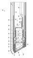
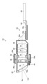
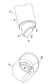
- FIG. 3 is an enlarged view of a first lens barrel, a second lens barrel, a sliding portion, and a holding member of the photographing apparatus shown in FIG. It is an exploded view of the photographing apparatus shown in FIG. It is explanatory drawing for demonstrating attachment of a cover to a 1st lens barrel. It is sectional drawing of a connecting pipe.
- FIG. 1 is a block diagram of an endoscope system 12 including the perspective mirror 10 of the first embodiment.
- the endoscope system 12 includes a perspective mirror 10 corresponding to the endoscope of the present invention, a processor device 14, a monitor 16, and a light source device 18.
- the perspective mirror 10 is a so-called rigid mirror, and includes an insertion unit 20, an operation unit 22, and an imaging device 24.
- the insertion portion 20 is formed in a substantially cylindrical shape and is inserted into the patient's body.
- the insertion portion 20 has a tip end, a base end, and a longitudinal axis Ax.
- a photographing device 24 also referred to as a camera unit, which will be described later, is provided at the tip of the insertion portion 20.
- a signal cable 26 (corresponding to the cable of the present invention) and a light guide 28 (optical fiber cable) are inserted in the insertion portion 20. In order to prevent the drawings from becoming complicated, the light guide 28 in the insertion portion 20 is not shown.
- the signal cable 26 connects the photographing device 24 and the processor device 14 described later together with the signal cable 27 described later.
- the tip of the signal cable 26 is connected to the photographing device 24, and the base end of the signal cable 26 is connected to an airtight connector (not shown) provided on the partition wall 23b described later.
- the light guide 28 is provided with a tip end portion (light emitting end face) on the tip end surface of the insertion portion 20, and a base end portion (light incident end face) thereof is connected to the light source device 18.
- the operation unit 22 is connected to the base end portion of the insertion unit 20.
- the operating portion 22 includes a base portion 22a, a rotating portion 22b, and an airtight case 22c.
- the base portion 22a is formed in a substantially cylindrical shape parallel to the longitudinal axis Ax.
- a rotating portion 22b is held at the tip of the base portion 22a so as to be relatively rotatable in the circumferential direction thereof.
- the "circumferential direction of " refers to the longitudinal direction of the longitudinal axis Ax or the axis parallel to the longitudinal axis Ax.
- the rotating portion 22b is formed in a substantially cylindrical shape parallel to the longitudinal axis Ax.
- a mantle tube 30 (see FIG. 2), which will be described later, is connected to the tip of the rotating portion 22b.
- the airtight case 22c is provided inside the rotating portion 22b.
- the airtight case 22c is formed in a substantially cylindrical shape parallel to the longitudinal axis Ax, and forms an airtight space together with the cover glass 39 and the outer cylinder 32 shown in FIG. 2 described later.
- An outer cylinder 32 is connected to the tip of the airtight case 22c.
- the cable holding portion 23a is rotatably held in the circumferential direction thereof, and a partition wall 23b is provided.
- the cable holding portion 23a has a shape extending along the longitudinal axis Ax and holds the signal cable 26. Further, a torque tube 64 (see FIG. 7) described later is connected to the tip end portion of the cable holding portion 23a, and the base portion 22a is connected to the base end portion of the cable holding portion 23a. Therefore, the rotating portion 22b and the airtight case 22c, the cable holding portion 23a, the signal cable 26, and the base portion 22a can rotate independently of each other, and one rotation is not transmitted to the other.
- the partition wall 23b airtightly seals the opening on the base end side of the above-mentioned airtight space formed by the airtight case 22c or the like.
- the partition wall 23b is provided with an airtight connector (not shown).
- the base end portion of the signal cable 26 and the tip end portion of the signal cable 27 described above are connected via this airtight connector.
- the base end of the signal cable 27 is connected to the processor device 14.
- the photographing device 24 and the processor device 14 are connected via the signal cables 26 and 27.
- the processor device 14 generates a photographed image (moving image) of the inside of the patient based on the image pickup signal input from the image pickup device 24 via the signal cables 26 and 27, and displays the photographed image on the monitor 16.
- the light source device 18 supplies illumination light to the light guide 28.
- the illumination light is emitted from the light emitting end surface of the tip portion of the light guide 28 provided on the tip surface of the insertion portion 20.
- FIG. 2 is an enlarged cross-sectional view of the tip of the insertion portion 20.
- the insertion portion 20 includes a substantially tubular outer tube 30, an outer tube 32, and a connecting tube 34 (also referred to as an inner tube) parallel to the longitudinal axis Ax.
- the mantle tube 30 constitutes the outer peripheral wall of the insertion portion 20.
- the opening at the tip of the mantle tube 30 is inclined from a posture perpendicular to the longitudinal axis Ax.
- the base end portion of the mantle tube 30 is connected to the rotating portion 22b as described above. As a result, the mantle tube 30 rotates integrally with the rotating portion 22b.
- the outer cylinder 32 is inserted and arranged inside the mantle tube 30.
- a base end portion of a substantially cylindrical cover holding portion 36 parallel to the longitudinal axis Ax is fitted and fixed to the opening on the tip end side of the outer cylinder 32. Further, the base end portion of the outer cylinder 32 is connected to the airtight case 22c as described above.
- connection pipe 34 is inserted and arranged inside the outer cylinder 32.
- the tip of the connecting tube 34 protrudes toward the tip of the insertion portion 20 from the tip of the cover holding portion 36.
- a torque tube 64 (see FIG. 7), which will be described later, is connected to the base end portion of the connecting pipe 34.
- the reference numeral OA in the figure is the optical axis of the optical system of the photographing apparatus 24.
- a cover 38 (also referred to as a case or a cap) that covers the photographing apparatus 24 is attached to the tip of the cover holding portion 36.
- the cover 38 constitutes the tip end portion of the insertion portion 20, and is formed in a substantially cylindrical shape parallel to the longitudinal axis Ax.
- the opening on the tip end side of the cover 38 is provided with a cover glass 39 having an inclined posture according to the inclination angle of the light incident surface 52a (see FIG. 3) of the perspective optical system 52 described later.
- An insertion passage 31 for a light guide 28 (not shown in FIG. 2) is formed between the inner peripheral surface of the mantle tube 30 and the outer peripheral surface of the outer cylinder 32.
- FIG. 3 is a cross-sectional view of the photographing apparatus 24.
- FIG. 4 is an enlarged view of the first lens barrel 40, the second lens barrel 42, the sliding portion 44, and the holding member 46 of the photographing apparatus 24 shown in FIG.
- FIG. 5 is an exploded view of the photographing apparatus 24 shown in FIG.
- the imaging device 24 captures images in a direction inclined with respect to the longitudinal axis Ax, that is, obliquely forward of the tip of the insertion portion 20.
- the photographing device 24 includes a first lens barrel 40, a second lens barrel 42, a sliding portion 44 (also referred to as a bearing), a holding member 46, a holder 48, an imaging unit 50, and a signal cable 26 described above. And prepare.
- the first lens barrel 40 is formed of a metal material such as stainless steel in a substantially cylindrical shape parallel to the longitudinal axis Ax.
- the perspective optical system 52 is housed in the first lens barrel 40.
- the base end portion of the first lens barrel which is the base end portion of the first lens barrel 40, is formed with a diameter-expanded portion 40a having a diameter larger than that of the other portions of the first lens barrel 40.
- the outer peripheral surface of the enlarged diameter portion 40a is formed parallel to the longitudinal axis Ax.
- the perspective optical system 52 (corresponding to the first optical system of the present invention) is composed of, for example, a plurality of lenses and prisms, is inclined from a posture perpendicular to the longitudinal axis Ax, and is incident with light facing the cover glass 39. It has a surface 52a and a light emitting surface 52b having a posture perpendicular to the longitudinal axis Ax.
- the perspective optical system 52 refracts light incident on the light incident surface 52a from a direction inclined with respect to the longitudinal axis Ax in a direction parallel to the longitudinal axis Ax, and then refracts the light from the light emitting surface 52b to a second lens barrel described later. It leads to the lens system 58 in 42.
- the configuration of the perspective optical system 52 is not particularly limited as long as it can guide the light incident from the direction inclined with respect to the longitudinal axis Ax to the lens system 58.
- the end face on the base end side of the first lens barrel 40 is formed perpendicular to the longitudinal axis Ax.
- a fitting hole 40c is formed in the base end surface 40b of the first lens barrel.
- the outer flange 42b of the second lens barrel 42 which will be described later, is fitted into the fitting hole 40c.
- the first lens barrel 40 is in the same direction as the rotating portion 22b via the outer tube 30, the outer cylinder 32, and the cover 38 (first). Rotate in the circumferential direction of the lens barrel 40).
- FIG. 6 is an explanatory diagram for explaining the attachment of the cover 38 to the first lens barrel 40.
- the first lens barrel 40 is provided with a pin-shaped positioning portion 54 projecting from the tip end side thereof.
- the positioning portion 54 engages with the hole-shaped engaged portion 38a formed on the inner peripheral surface of the cover 38.
- the rotational position of the first lens barrel 40 in the cover 38 in the circumferential direction can be positioned at a position where the light incident surface 52a faces the cover glass 39.
- the cover 38 can be easily attached to the first lens barrel 40.
- the shapes and configurations of the positioning portion 54 and the engaged portion 38a can be appropriately changed.
- the second lens barrel 42 is arranged on the base end side of the first lens barrel 40.
- the first lens barrel 40 and the second lens barrel 42 are relatively rotatable in the circumferential direction of the first lens barrel 40 and the second lens barrel 42 via the sliding portion 44 and the pressing member 46 described later.
- the second lens barrel 42 is formed of a metal material such as stainless steel in a substantially cylindrical shape parallel to the longitudinal axis Ax.
- the second lens barrel 42 of the present embodiment is formed to have a smaller diameter than the enlarged diameter portion 40a as a whole, but at least the tip portion 42a of the second lens barrel, which is the tip portion of the second lens barrel 42, is expanded.
- the shape is not particularly limited as long as the diameter is smaller than the diameter portion 40a.
- a lens system 58 corresponding to the second optical system of the present invention is housed in the second lens barrel 42.
- the lens system 58 is composed of a plurality of lenses and has an optical axis OA parallel to the longitudinal axis Ax.
- the lens system 58 guides the light that has passed through the perspective optical system 52 to the image pickup unit 50 described later.
- An outer flange 42b corresponding to the first projecting portion of the present invention is formed on the distal end side of the outer peripheral surface of the second lens barrel tip portion 42a, that is, along the circumferential direction of the outer peripheral surface.
- the outer diameter of the outer flange 42b is formed to match the diameter of the fitting hole 40c described above, and the outer flange 42b fits into the fitting hole 40c.
- a plurality of engaging claws may be provided around the outer peripheral surface of the tip end portion 42a of the second lens barrel.
- the sliding portion 44 is formed of, for example, ceramics in a substantially ring shape parallel to the longitudinal axis Ax.
- the sliding portion 44 is formed separately from the second lens barrel 42, but is externally fitted and fixed to the outer peripheral surface of the second lens barrel tip portion 42a by a method such as adhesion, and the second lens barrel 42. It rotates in the circumferential direction integrally with.
- the outer diameter of the sliding portion 44 is formed to be the same as (including substantially the same) the outer diameter of the enlarged diameter portion 40a.
- the sliding portion 44 is in contact with the outer flange 42b from the base end side of the outer flange 42b and is in contact with the enlarged diameter portion 40a.
- the sliding portion 44 has a sliding portion tip surface 44a which is an end surface on the distal end side thereof and a sliding portion base end surface 44b which is an end surface on the proximal end side thereof (see FIG. 5). Both the sliding portion tip surface 44a and the sliding portion base end surface 44b are planes perpendicular to the longitudinal axis Ax.
- the sliding portion tip surface 44a is in contact with the first lens barrel base end surface 40b and the outer flange 42b.
- the sliding portion base end surface 44b is in contact with the inner flange 46b of the pressing member 46 described later.
- the holding member 46 is formed of a metal material such as stainless steel in a substantially cylindrical shape parallel to the longitudinal axis Ax.
- the pressing member 46 is externally fitted from the enlarged diameter portion 40a to the sliding portion 44.
- the pressing member 46 has an inner peripheral surface 46a of the pressing member and an inner flange 46b. Further, the proximal end portion of the pressing member 46 extends toward the proximal end side from the proximal end portion of the sliding portion 44 described above.
- the inner peripheral surface 46a of the pressing member is in contact with both the outer peripheral surface of the enlarged diameter portion 40a and the outer peripheral surface of the sliding portion 44.
- the inner peripheral surface 46a of the pressing member has a fixed region R1 fixed to the outer peripheral surface of the enlarged diameter portion 40a by a method such as adhesion, and a sliding region R2 in which the outer peripheral surface of the sliding portion 44 is slidably contacted.
- the first lens barrel 40 is fixed to the holding member 46 so as not to be rotatable in the circumferential direction, but the sliding portion 44 and the second lens barrel 42 are rotatably held in the circumferential direction. Therefore, the first lens barrel 40 and the second lens barrel 42 are relatively rotatable in the circumferential direction via the sliding portion 44 and the holding member 46.
- the inner flange 46b corresponds to the movement restricting portion and the second projecting portion of the present invention, and is provided around the inner peripheral surface 46a of the pressing member at the base end portion of the pressing member 46.
- the inner flange 46b is in contact with the sliding portion base end surface 44b.
- the contact surface (tip surface) of the inner flange 46b in contact with the base end surface 44b of the sliding portion is also a surface perpendicular to the longitudinal axis Ax.
- the inner flange 46b moves in the axial direction of the longitudinal axis Ax of the sliding portion 44 (the direction along the longitudinal axis Ax, that is, the direction parallel to the longitudinal axis Ax) with the first lens barrel base end surface 40b.
- a plurality of engaging claws (not shown) provided around the inner peripheral surface 46a of the pressing member may be used.
- the sliding portion tip surface 44a and the first lens barrel base end surface 40b are formed. It slides (sliding), the outer peripheral surface of the sliding portion 44 and the sliding region R2 of the inner peripheral surface 46a of the holding member slide, and the base end surface 44b of the sliding portion and the inner flange 46b slide. ..
- the sliding portion 44 is made of the same material (metal material) as at least one of the first lens barrel 40 and the holding member 46, so-called galling in which at least one of the sliding portions 44 is in close contact with each other. (Including welding, welding, or welding) may occur.
- the sliding portion 44 is made of a material different from that of the first lens barrel 40 and the pressing member 46, and has good slidability with the first lens barrel 40 and the pressing member 46 (the present embodiment). By forming it from ceramics in the form), it is possible to prevent the above-mentioned galling from occurring.
- the holder 48 is formed of a metal material such as aluminum in a substantially cylindrical shape parallel to the longitudinal axis Ax.
- the holder 48 is connected and fixed (outer fitting fixed) from the base end side of the second lens barrel 42 to the base end portion of the second lens barrel 42. Further, the holder 48 is fitted and fixed in the opening on the tip end side of the connection pipe 34 described above. As a result, the second lens barrel 42, the holder 48, and the connecting tube 34 rotate integrally in the circumferential direction.
- the image pickup unit 50 which will be described later, is held in the opening on the base end side of the holder 48, and more specifically, the prism 50a of the image pickup unit 50 is held. Therefore, the image pickup unit 50 rotates integrally with the second lens barrel 42 in the circumferential direction via the holder 48.
- the image pickup unit 50 captures the light incident through the perspective optical system 52 and the lens system 58.
- the image pickup unit 50 includes a prism 50a, an image pickup element 50b, and a circuit board 50c.
- the prism 50a corresponds to the dioptric optical element of the present invention, and is held in the opening on the proximal end side of the holder 48 as described above.
- the prism 50a refracts the light incident through the lens system 58 by 90 degrees.
- the image pickup element 50b is fixed to the prism 50a in a state of being mounted on the circuit board 50c, and images the light refracted by the prism 50a.
- a CCD (Charge Coupled Device) type image sensor or a CMOS (Complementary Metal Oxide Semiconductor) type image sensor can be used as the image sensor 50b.
- the circuit board 50c controls the drive of the image pickup element 50b. Further, the tip of the signal cable 26 is connected to the circuit board 50c via the connector 60. Then, the circuit board 50c outputs the image pickup signal of the image pickup element 50b to the signal cable 26 via the connector 60.
- FIG. 7 is a cross-sectional view of the connecting pipe 34.
- the cable base end portion on the side opposite to the cable tip portion of the signal cable 26 connected to the circuit board 50c (imaging unit 50) is a twist-deformable loose wire structure 26a, that is, the signal cable 26. It is a structure in which a plurality of signal lines are not integrated but separated. As a result, disconnection of the signal cable 26 is prevented when the second lens barrel 42 is rotated relative to the first lens barrel 40 in the circumferential direction, that is, when the image pickup unit 50 is rotated in the circumferential direction. ..
- the tip of the torque tube 64 is fitted and connected to the opening on the base end side of the connecting pipe 34 via the connecting member 65.
- the connecting pipe 34 and the torque tube 64 may be directly connected without the connection member 65. Further, the base end portion of the torque tube 64 is connected to the cable holding portion 23a as described above.
- the torque tube 64 is a tube-shaped coil body formed by spirally winding a plurality of strands (not shown) along the longitudinal axis Ax.
- the torque tube 64 transmits the rotational torque of the base 22a (cable holding portion 23a) of the operating portion 22 to the second lens barrel 42 via the connecting tube 34 and the like.
- the torque tube 64 a coil body (coil spring or the like) formed by spirally winding a single wire along the longitudinal axis Ax may be used.
- the rotational torque referred to here includes the torque for rotating the second lens barrel 42 in the circumferential direction with respect to the first lens barrel 40, as well as the circumferential direction of the second lens barrel 42 with respect to the first lens barrel 40.
- the torque for maintaining the posture of (posture maintenance torque) is also included. As a result, even when the rotating portion 22b is rotated to rotate the first lens barrel 40 in the circumferential direction, the posture of the second lens barrel 42 in the circumferential direction can be maintained.
- FIGS. 8 to 10 are descriptions for explaining the assembly of the photographing apparatus 24 of the first embodiment, particularly the assembly of the first lens barrel 40, the second lens barrel 42 and the sliding portion 44, and the holding member 46. It is a figure.
- the reference numeral U indicates an upward direction (vertically above), and the reference numeral D indicates a downward direction (vertically downward).
- the positioning portion 54 of the first lens barrel 40 is not shown as appropriate.
- the first lens barrel 40 is set on the support base 68 with the tip end side of the first lens barrel 40 facing downward.
- the outer flange 42b of the second lens barrel 42 to which the sliding portion 44 is fitted and fixed in advance is fitted into the fitting hole 40c of the first lens barrel 40.
- the sliding portion tip surface 44a of the sliding portion 44 is abutted against the first lens barrel base end surface 40b of the first lens barrel 40 using the outer flange 42b and the fitting hole 40c as guides.
- the adhesive 70 is applied to the outer peripheral surface of the enlarged diameter portion 40a.
- the pressing member 46 is fitted into the outer peripheral surfaces of both the enlarged diameter portion 40a and the sliding portion 44 from the base end side of the second lens barrel 42, and further.
- the inner flange 46b is abutted against the sliding portion base end surface 44b.
- the pressing member 46 is externally fitted over the outer peripheral surfaces of both the enlarged diameter portion 40a and the sliding portion 44, and the pressing member 46 is adhesively fixed to the outer peripheral surface of the enlarged diameter portion 40a.
- a weight (not shown) is attached to the base end side (upward U side) of the inner flange 46b so that the sliding portion tip surface 44a abuts against the first lens barrel base end surface 40b and the sliding portion base. It is preferable to ensure that the inner flange 46b abuts against the end surface 44b.
- the holder 48 is externally fitted and fixed to the second lens barrel 42, and the prism 50a of the imaging unit 50 is further fixed to the opening on the base end side of the holder 48. This completes the assembly of the photographing device 24.
- the sliding portion tip surface 44a is abutted against the first lens barrel base end surface 40b, and the inner flange 46b is abutted against the sliding portion base end surface 44b. It is possible to secure the parallelism between the lens barrel 40 and the second lens barrel 42 and prevent rattling. As a result, it is possible to prevent the perspective optical system 52 of the first lens barrel 40 and the lens system 58 of the second lens barrel 42 from tilting (tilting of the optical axis OA).
- the photographing device 24 by ensuring the component accuracy (surface accuracy of the sliding surface SC) of the first lens barrel 40, the second lens barrel 42, the sliding portion 44, and the holding member 46, the photographing device 24 The above-mentioned trouble can be prevented without requiring complicated optical adjustment at the time of assembly.
- the outer flange 42b is fitted into the fitting hole 40c, and the inner peripheral surface 46a of the pressing member is externally attached to the outer peripheral surfaces of both the enlarged diameter portion 40a and the sliding portion 44.
- the 1 lens barrel 40 and the 2nd lens barrel 42 can be automatically aligned. That is, in the first embodiment, by ensuring the accuracy of the parts of the first lens barrel 40, the second lens barrel 42, the sliding portion 44, and the holding member 46, complicated optical adjustment is required when assembling the photographing device 24. It is possible to prevent the optical axis runout (eccentricity of the optical axis OA) of the perspective optical system 52 and the lens system 58. Further, since the above-mentioned automatic alignment of the first lens barrel 40 and the second lens barrel 42 can be realized with a small number of parts, it is possible to reduce the accumulation of tolerances for each part.
- good optical performance of the photographing apparatus 24 can be obtained by suppressing the occurrence of troublesomeness, optical axis runout, and rattling without requiring complicated optical adjustment when assembling the photographing apparatus 24. Be done. Further, since complicated optical adjustment is not required, it is possible to reduce the occurrence of defective products that fail in the image quality inspection after the assembly and adjustment of the photographing apparatus 24 (squint mirror 10).
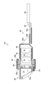
- FIG. 11 is a cross-sectional view of the photographing apparatus 24 of the second embodiment.
- the second lens barrel 42 and the sliding portion 44 are separately formed, but in the photographing device 24 of the second embodiment, the second lens barrel 42 and the sliding portion 44 are formed. It is provided with an integrally molded body in which and is integrally formed.
- the photographing device 24 and the perspective mirror 10 of the second embodiment have basically the same configuration as that of the first embodiment except that the integrally molded body of the second lens barrel 42 and the sliding portion 44 is provided. Therefore, the same reference numerals are given to those having the same function or configuration as those of the first embodiment, and the description thereof will be omitted.
- the sliding portion 44 is integrally formed on the outer peripheral surface of the tip portion 42a of the second lens barrel, and the formation of the outer flange 42b is omitted.
- the tip surface 44a of the sliding portion is abutted against the base end surface 40b of the first lens barrel, and the inner flange 46b is abutted against the base end surface 44b of the sliding portion. Therefore, it is possible to prevent troublesomeness and rattling. Further, by circumscribing the inner peripheral surface 46a of the pressing member to the outer peripheral surfaces of both the enlarged diameter portion 40a and the sliding portion 44, it is possible to prevent the optical axis runout. As a result, the same effect as that of the first embodiment can be obtained.
- the second lens barrel 42 and the sliding portion 44 are integrally formed, it is not necessary to externally fit and fix the sliding portion 44 to the outer peripheral surface of the second lens barrel tip portion 42a. The assembly man-hours can be reduced.
- the sliding portion 44 is made of the same material (metal material) as at least one of the first lens barrel 40 and the holding member 46, the above-mentioned galling may occur. Therefore, in the second embodiment, the first lens barrel 40 and the holding member 46 are formed of, for example, stainless steel as in the first embodiment, and the second lens barrel 42 and the sliding portion 44 are formed of, for example, brass. is doing. This makes it possible to prevent the above-mentioned galling from occurring also in the second embodiment.
- the material of the sliding portion 44 (second lens barrel 42) and the material of the first lens barrel 40 and the holding member 46 are not particularly limited as long as they are different from each other.
- FIG. 12 is an explanatory diagram for explaining the black layer 72 formed on the inner peripheral surfaces of the first lens barrel 40 and the second lens barrel 42.
- a black layer 72 corresponding to the antireflection layer of the present invention by a known black treatment such as coating or plating ( A black film) is formed on the inner peripheral surfaces of both the first lens barrel 40 and the second lens barrel 42.
- the black layer 72 corresponds to the antireflection layer of the present invention, and absorbs light to prevent reflection of light on the inner peripheral surfaces of both the first lens barrel 40 and the second lens barrel 42.
- the sliding surface SC between the first lens barrel 40 and the sliding portion 44 and the sliding surface SC between the sliding portion 44 and the holding member 46 are required to have high dimensional accuracy. Therefore, in order to eliminate the influence of the film thickness tolerance of the black layer 72 due to the black treatment, the above-mentioned sliding surface SC, that is, the first lens barrel base end surface 40b, the sliding portion tip surface 44a, and the outer periphery of the sliding portion 44.
- the surface and the base end surface 44b of the sliding portion are non-formed surfaces of the black layer 72. As a result, it is possible to suppress the reflection of light in the first lens barrel 40 and the second lens barrel 42 and secure high dimensional accuracy of the sliding surface SC.
- the black layer 72 may be formed on the inner peripheral surfaces of both the first lens barrel 40 and the second lens barrel 42.
- FIG. 13 is an explanatory diagram for explaining a modified example of the imaging unit 50.
- the image pickup unit 50 of each of the above embodiments has the light incident through the perspective optical system 52 and the lens system 58 refracted by the prism 50a and then imaged by the image pickup element 50b, but the light is not refracted by the prism 50a.
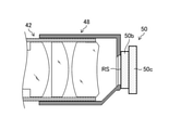
- the image pickup element 50b may be used for image pickup. In this case, as shown in FIG. 13, the image sensor 50b is held in the opening on the base end side of the holder 48.
- the image pickup device 50b is held by the holder 48 in a posture perpendicular to the longitudinal axis Ax (optical axis OA of the lens system 58), and has a light receiving surface RS orthogonal to the optical axis OA of the lens system 58.
- the pressing member 46 is fixed to the outer peripheral surface of the enlarged diameter portion 40a and slidable on the outer peripheral surface of the sliding portion 44, but the pressing member 46 is attached to the outer peripheral surface of the sliding portion 44. It may be fixed and slidable on the outer peripheral surface of the enlarged diameter portion 40a.
- the inner flange 46b is provided around the inner peripheral surface 46a of the holding member at the tip of the holding member 46. Further, by providing the inner flange 46b on the inner peripheral surface 46a of both the tip end portion and the base end portion of the pressing member 46, the pressing member 46 can be formed on the outer peripheral surface of the enlarged diameter portion 40a and the sliding portion 44. It may be slidable on both outer peripheral surfaces.
- the enlarged diameter portion 40a is formed in the first lens barrel 40, but the entire first lens barrel 40 may be formed with the same outer diameter as the enlarged diameter portion 40a.
- the holding member 46 may be fitted on the entire outer peripheral surface of the first lens barrel 40.
- the outer diameters of the second lens barrel tip 42a of the second lens barrel 42 and the base end of the second lens barrel 42 are the same, but even if the outer diameters of both are not the same. good.
- the outer diameter of the enlarged diameter portion 40a and the outer diameter of the sliding portion 44 are the same, but if the pressing member 46 can be fitted externally, even if the outer diameters of both are not the same. good.
- the second lens barrel 42 and the holder 48 are formed separately, but both may be integrally molded.
- the photographing device 24 is provided with a holder 48 and an imaging unit 50, but the photographing device 24 of the present invention has a first lens barrel 40, a second lens barrel 42, a sliding portion 44, and a presser.
- the member 46 may be traded as one unit.
- the perspective mirror 10 has been described by taking a rigid mirror as an example, but the present invention can also be applied to a flexible mirror. Further, in each of the above embodiments, the perspective mirror 10 has been described as an example of the endoscope of the present invention. The invention is applicable.
Landscapes
- Health & Medical Sciences (AREA)
- Life Sciences & Earth Sciences (AREA)
- Physics & Mathematics (AREA)
- Engineering & Computer Science (AREA)
- Surgery (AREA)
- Optics & Photonics (AREA)
- Heart & Thoracic Surgery (AREA)
- Animal Behavior & Ethology (AREA)
- Radiology & Medical Imaging (AREA)
- Nuclear Medicine, Radiotherapy & Molecular Imaging (AREA)
- Biophysics (AREA)
- Biomedical Technology (AREA)
- Veterinary Medicine (AREA)
- Medical Informatics (AREA)
- Molecular Biology (AREA)
- Pathology (AREA)
- General Health & Medical Sciences (AREA)
- Public Health (AREA)
- Multimedia (AREA)
- Signal Processing (AREA)
- General Physics & Mathematics (AREA)
- Astronomy & Astrophysics (AREA)
- Manufacturing & Machinery (AREA)
- Endoscopes (AREA)
- Instruments For Viewing The Inside Of Hollow Bodies (AREA)
- Lens Barrels (AREA)
Abstract
Description
図1は、第1実施形態の斜視鏡10を備える内視鏡システム12の構成図である。図1に示すように、内視鏡システム12は、本発明の内視鏡に相当する斜視鏡10と、プロセッサ装置14と、モニタ16と、光源装置18と、を備える。
図3は、撮影装置24の断面図である。図4は、図3中に示した撮影装置24の第1鏡筒40、第2鏡筒42、摺動部44、及び押さえ部材46の拡大図である。図5は、図4に示した撮影装置24の分解図である。図3から図5と、既述の図2とに示すように、撮影装置24は、長手軸Axに対して傾斜した方向、すなわち挿入部20の先端部の斜め前方の撮影を行う。
図11は、第2実施形態の撮影装置24の断面図である。上記第1実施形態の撮影装置24では第2鏡筒42と摺動部44とが別体に形成されているが、第2実施形態の撮影装置24は第2鏡筒42と摺動部44とが一体に形成された一体成形体を備える。なお、第2実施形態の撮影装置24及び斜視鏡10は、第2鏡筒42及び摺動部44の一体成形体を備える点を除けば、上記第1実施形態と基本的に同じ構成であるので、上記第1実施形態と機能又は構成上同一のものについては同一符号を付してその説明は省略する。
図13は、撮像部50の変形例を説明するための説明図である。上記各実施形態の撮像部50は、斜視光学系52及びレンズ系58を通して入射した光をプリズム50aで屈折した後で撮像素子50bにより撮像しているが、この光をプリズム50aで屈折させることなく撮像素子50bで撮像してもよい。この場合には、図13に示すように、ホルダ48の基端側の開口部に撮像素子50bを保持する。この撮像素子50bは、長手軸Ax(レンズ系58の光軸OA)に対して垂直な姿勢でホルダ48に保持され、且つレンズ系58の光軸OAに直交する受光面RSを有する。
12 内視鏡システム
14 プロセッサ装置
16 モニタ
18 光源装置
20 挿入部
22 操作部
22a 基部
22b 回転部
22c 気密ケース
23a ケーブル保持部
23b 隔壁
24 撮影装置
26 信号ケーブル
26a バラ線構造
27 信号ケーブル
28 ライトガイド
30 外套管
31 挿通路
32 外筒
34 接続管
36 カバー保持部
38 カバー
38a 被係合部
39 カバーガラス
40 第1鏡筒
40a 拡径部
40b 第1鏡筒基端面
40c 嵌合穴
42 第2鏡筒
42a 第2鏡筒先端部
42b 外フランジ
44 摺動部
44a 摺動部先端面
44b 摺動部基端面
46 押さえ部材
46a 押さえ部材内周面
46b 内フランジ
48 ホルダ
50 撮像部
50a プリズム
50b 撮像素子
50c 回路基板
52 斜視光学系
52a 光入射面
52b 光出射面
54 位置決め部
58 レンズ系
60 コネクタ
64 トルクチューブ
65 接続部材
68 支持台
70 接着剤
72 黒色層
Ax 長手軸
OA 光軸
R1 固定領域
R2 摺動領域
RS 受光面
SC 摺動面
Claims (20)
- 長手軸を有する内視鏡の挿入部の先端部に設けられた撮影装置において、
第1光学系を収容する第1鏡筒と、
前記第1鏡筒の基端側に配置され、前記第1光学系を通過した光が入射する第2光学系を収容する第2鏡筒であって、且つ前記第1鏡筒の基端部である第1鏡筒基端部よりも小径の先端部である第2鏡筒先端部を有する第2鏡筒と、
前記第2鏡筒先端部の外周面に周設される摺動部であって、且つ前記第1鏡筒基端部に接する摺動部と、
前記第1鏡筒基端部から前記摺動部に亘って外嵌された押さえ部材と、
を備え、
前記押さえ部材が、前記第1鏡筒基端部の外周面及び前記摺動部の外周面の双方に接する押さえ部材内周面と、前記第1鏡筒基端部との間で前記摺動部の前記長手軸の軸方向の移動を規制する移動規制部と、を有し、
前記摺動部及び前記押さえ部材を介して、前記第1鏡筒及び前記第2鏡筒が前記第1鏡筒及び前記第2鏡筒の周方向に相対回転自在である撮影装置。 - 前記第1光学系及び前記第2光学系を通して入射した光を撮像する撮像部を備える請求項1に記載の撮影装置。
- 前記撮像部が、前記第2光学系から入射した光を屈折させる屈折光学素子と、前記屈折光学素子により屈折された光を撮像する撮像素子と、を備える請求項2に記載の撮影装置。
- 前記撮像部が、前記第2光学系の基端側に配置され且つ前記第2光学系の光軸に直交する受光面を有する撮像素子を含む請求項2に記載の撮影装置。
- 前記第2鏡筒の基端側から前記第2鏡筒に接続固定され、前記撮像部を保持する筒状のホルダを備える請求項3又は4に記載の撮影装置。
- 前記第2鏡筒と前記摺動部とが別体で形成されており、前記第2鏡筒先端部の外周面に前記摺動部が外嵌固定されている請求項1から5のいずれか1項に記載の撮影装置。
- 前記第2鏡筒先端部の外周面の先端側に周設された第1突設部と、
前記第1鏡筒基端部の基端側の端面である第1鏡筒基端面に形成され、前記第1突設部が嵌合する嵌合穴と、
を備え、
前記摺動部が、前記第1突設部の基端側から前記第1突設部に接した状態で前記第2鏡筒先端部の外周面に外嵌固定されている請求項6に記載の撮影装置。 - 前記第2鏡筒の前記第2鏡筒先端部と前記摺動部とが一体化した一体成形体を備える請求項1から5のいずれか1項に記載の撮影装置。
- 前記摺動部の材質が、前記第1鏡筒の材質及び前記押さえ部材の材質とは異なる請求項1から8のいずれか1項に記載の撮影装置。
- 前記押さえ部材内周面が、前記第1鏡筒基端部の外周面に固定される固定領域と、前記摺動部の外周面が摺動可能に接する摺動領域と、を有する請求項1から9のいずれか1項に記載の撮影装置。
- 前記第1鏡筒の内周面及び前記第2鏡筒の内周面に形成された反射防止層を備え、
前記第1鏡筒の前記摺動部に接する面と、前記摺動部の前記第1鏡筒及び前記押さえ部材に接する面と、が前記反射防止層の非形成面である請求項1から10のいずれか1項に記載の撮影装置。 - 前記第1鏡筒基端部が、前記第1鏡筒の他の部分よりも拡径された拡径部である請求項1から11のいずれか1項に記載の撮影装置。
- 前記第1鏡筒基端部の外径と、前記摺動部の外径とが同一である請求項1から12のいずれか1項に記載の撮影装置。
- 前記第1鏡筒基端部の基端側の端面である第1鏡筒基端面と、前記摺動部の先端側の端面である摺動部先端面と、が前記長手軸に対して垂直な面であり、
前記摺動部先端面が、前記第1鏡筒基端面に接し、
前記移動規制部が、前記第1鏡筒基端面との間で前記摺動部の前記軸方向の移動を規制する請求項1から13のいずれか1項に記載の撮影装置。 - 前記押さえ部材の基端部が、前記摺動部の基端部よりも基端側に延出されており、
前記移動規制部が、前記押さえ部材の基端部の前記押さえ部材内周面に周設された第2突設部であり、
前記第2突設部が、前記摺動部の基端側の端面である摺動部基端面に接して、前記第1鏡筒基端面との間で前記摺動部の前記軸方向の移動を規制し、
前記摺動部基端面と、前記摺動部基端面に接する第2突設部の接触面と、が前記長手軸に対して垂直な面である請求項14に記載の撮影装置。 - 前記第1光学系が、前記長手軸に対して傾斜した方向から入射した光を前記第2光学系に導く斜視光学系である請求項1から15のいずれか1項に記載の撮影装置。
- 前記斜視光学系が、前記長手軸に対して垂直な姿勢から傾斜した光入射面を有し、
前記第1鏡筒の先端部に設けられ、前記第1鏡筒の先端部を覆う筒状のカバーと、
前記カバー内の先端部に設けられ、前記光入射面の傾斜角度に合わせた傾斜姿勢のカバーガラスと、
前記第1鏡筒に設けられ且つ前記カバー内に設けられた被係合部に係合して、前記カバー内での前記第1鏡筒の前記周方向の回転位置を、前記光入射面が前記カバーガラスに対向する位置に位置決めする位置決め部と、
を備える請求項16に記載の撮影装置。 - 前記第1光学系及び前記第2光学系を通して入射した光を撮像する撮像部と、
前記撮像部に接続されたケーブルと、
を備え、
前記ケーブルの前記撮像部に接続されるケーブル先端部とは反対側のケーブル基端部が、ねじり変形可能に構成されている請求項1から17のいずれか1項に記載の撮影装置。 - 長手軸を有する挿入部と、
前記挿入部の先端部に設けられた請求項1から18のいずれか1項に記載の撮影装置と、
を備える内視鏡。 - 前記撮影装置が、
前記第1光学系及び前記第2光学系を通して入射した光を撮像する撮像部と、
前記第2鏡筒の基端側から前記第2鏡筒に接続固定され、前記撮像部を保持する筒状のホルダと、
を備え、
前記周方向に回転可能な筒状のトルクチューブと、
前記ホルダと前記トルクチューブとを接続する筒状の接続管であって、且つ前記トルクチューブの回転トルクを前記ホルダに伝達する接続管と、
を備える請求項19に記載の内視鏡。
Priority Applications (4)
| Application Number | Priority Date | Filing Date | Title |
|---|---|---|---|
| CN202180046275.7A CN115735147B (zh) | 2020-07-30 | 2021-07-26 | 摄影装置及内窥镜 |
| JP2022540265A JP7463522B2 (ja) | 2020-07-30 | 2021-07-26 | 撮影装置及び内視鏡 |
| DE112021004125.8T DE112021004125T5 (de) | 2020-07-30 | 2021-07-26 | Bildaufnahmevorrichtung und endoskop |
| US18/069,154 US12316944B2 (en) | 2020-07-30 | 2022-12-20 | Image pickup device and endoscope |
Applications Claiming Priority (2)
| Application Number | Priority Date | Filing Date | Title |
|---|---|---|---|
| JP2020-129459 | 2020-07-30 | ||
| JP2020129459 | 2020-07-30 |
Related Child Applications (1)
| Application Number | Title | Priority Date | Filing Date |
|---|---|---|---|
| US18/069,154 Continuation US12316944B2 (en) | 2020-07-30 | 2022-12-20 | Image pickup device and endoscope |
Publications (1)
| Publication Number | Publication Date |
|---|---|
| WO2022024952A1 true WO2022024952A1 (ja) | 2022-02-03 |
Family
ID=80035639
Family Applications (1)
| Application Number | Title | Priority Date | Filing Date |
|---|---|---|---|
| PCT/JP2021/027444 Ceased WO2022024952A1 (ja) | 2020-07-30 | 2021-07-26 | 撮影装置及び内視鏡 |
Country Status (5)
| Country | Link |
|---|---|
| US (1) | US12316944B2 (ja) |
| JP (1) | JP7463522B2 (ja) |
| CN (1) | CN115735147B (ja) |
| DE (1) | DE112021004125T5 (ja) |
| WO (1) | WO2022024952A1 (ja) |
Citations (2)
| Publication number | Priority date | Publication date | Assignee | Title |
|---|---|---|---|---|
| US20060058581A1 (en) * | 2004-09-11 | 2006-03-16 | Olympus Winter & Ibe Gmbh | Video endoscope with a rotatable video camera |
| JP2017500997A (ja) * | 2013-12-13 | 2017-01-12 | インテグレーテッド エンドスコピー、 インコーポレーテッド | 熱伝導性レンズクレードルを使用した医用画像形成装置 |
Family Cites Families (13)
| Publication number | Priority date | Publication date | Assignee | Title |
|---|---|---|---|---|
| JP2002336190A (ja) * | 2001-03-12 | 2002-11-26 | Olympus Optical Co Ltd | 内視鏡 |
| KR20050102841A (ko) * | 2004-04-23 | 2005-10-27 | 삼성전자주식회사 | 조리개 장치 및 조리개 구동장치 및 이를 가지는카메라유닛과 조리개 제어방법 |
| US10357149B2 (en) | 2005-04-05 | 2019-07-23 | Integrated Endoscopy, Inc. | Medical imaging device using thermally conducting lens cradle |
| US7885010B1 (en) * | 2008-01-14 | 2011-02-08 | Integrated Medical Systems International | Endoscope objective lens and method of assembly |
| JP5155494B2 (ja) * | 2010-11-09 | 2013-03-06 | オリンパスメディカルシステムズ株式会社 | 内視鏡用撮像装置 |
| JP5833400B2 (ja) * | 2011-09-30 | 2015-12-16 | 富士フイルム株式会社 | 内視鏡用撮影レンズユニット及びカメラモジュール |
| CN104337492A (zh) * | 2014-05-04 | 2015-02-11 | 中国科学院光电研究院 | 一种用于内窥镜摄像适配器的光机结构 |
| CN106455922B (zh) * | 2014-05-15 | 2018-03-27 | 奥林巴斯株式会社 | 光学单元和具有该光学单元的内窥镜 |
| JP6006458B1 (ja) * | 2014-11-19 | 2016-10-12 | オリンパス株式会社 | 内視鏡用撮像ユニット |
| WO2016158352A1 (ja) * | 2015-03-31 | 2016-10-06 | 富士フイルム株式会社 | 内視鏡 |
| EP3278711B1 (en) * | 2015-03-31 | 2021-05-26 | FUJIFILM Corporation | Optical unit and endoscope |
| WO2016170838A1 (ja) * | 2015-04-23 | 2016-10-27 | オリンパス株式会社 | 内視鏡システム |
| CN111449609B (zh) * | 2020-04-10 | 2025-04-25 | 青岛奥美克医疗科技有限公司 | 用于内窥镜系统的适配器及内窥镜系统 |
-
2021
- 2021-07-26 CN CN202180046275.7A patent/CN115735147B/zh active Active
- 2021-07-26 DE DE112021004125.8T patent/DE112021004125T5/de active Pending
- 2021-07-26 WO PCT/JP2021/027444 patent/WO2022024952A1/ja not_active Ceased
- 2021-07-26 JP JP2022540265A patent/JP7463522B2/ja active Active
-
2022
- 2022-12-20 US US18/069,154 patent/US12316944B2/en active Active
Patent Citations (2)
| Publication number | Priority date | Publication date | Assignee | Title |
|---|---|---|---|---|
| US20060058581A1 (en) * | 2004-09-11 | 2006-03-16 | Olympus Winter & Ibe Gmbh | Video endoscope with a rotatable video camera |
| JP2017500997A (ja) * | 2013-12-13 | 2017-01-12 | インテグレーテッド エンドスコピー、 インコーポレーテッド | 熱伝導性レンズクレードルを使用した医用画像形成装置 |
Also Published As
| Publication number | Publication date |
|---|---|
| CN115735147A (zh) | 2023-03-03 |
| DE112021004125T5 (de) | 2023-06-29 |
| JP7463522B2 (ja) | 2024-04-08 |
| US12316944B2 (en) | 2025-05-27 |
| CN115735147B (zh) | 2025-09-09 |
| JPWO2022024952A1 (ja) | 2022-02-03 |
| US20230131639A1 (en) | 2023-04-27 |
Similar Documents
| Publication | Publication Date | Title |
|---|---|---|
| US4439030A (en) | Connecting device for an endoscopic television camera | |
| US9435750B2 (en) | Borescope | |
| US6554767B2 (en) | Endoscopic optical adapter freely attachable to and detachable from endoscope | |
| CN102483503B (zh) | 摄像单元 | |
| WO2010084914A1 (ja) | 光学素子及びそれを用いた光学ユニット | |
| JP5161529B2 (ja) | 内視鏡 | |
| US6346076B1 (en) | Endoscope | |
| WO2022024952A1 (ja) | 撮影装置及び内視鏡 | |
| JP3595472B2 (ja) | 主焦点ユニット | |
| JP7396876B2 (ja) | 内面画像検査装置及び内面画像検査システム | |
| JP2000089136A (ja) | 内視鏡の光学系駆動機構 | |
| CN118614843A (zh) | 内窥镜摄像装置及内窥镜 | |
| JP2022039345A (ja) | 内視鏡 | |
| CN224023536U (zh) | 安装基座、光学耦合器和内窥镜系统 | |
| US20250082185A1 (en) | Endoscope imaging device and endoscope | |
| JP3026501B2 (ja) | 内視鏡用コネクタ装置 | |
| CN219594535U (zh) | 一体化偏振光内窥镜摄像头 | |
| JP5479012B2 (ja) | 連結部材および望遠鏡 | |
| JPS63281121A (ja) | 内視鏡用光学アダプタ装置 | |
| JPH1123983A (ja) | 内視鏡のテレビカメラ装置及びその合焦方法 | |
| JP2017058484A (ja) | カム機構及び光学機器 | |
| JP2022039346A (ja) | 内視鏡及び撮影装置 | |
| WO2026013839A1 (ja) | 撮像ユニット、内視鏡、および撮像ユニットの組立方法 | |
| JP2017223806A (ja) | 検査装置 | |
| JP2532370Y2 (ja) | 内視鏡のイメージガイド位置調整機構 |
Legal Events
| Date | Code | Title | Description |
|---|---|---|---|
| 121 | Ep: the epo has been informed by wipo that ep was designated in this application |
Ref document number: 21850139 Country of ref document: EP Kind code of ref document: A1 |
|
| ENP | Entry into the national phase |
Ref document number: 2022540265 Country of ref document: JP Kind code of ref document: A |
|
| 122 | Ep: pct application non-entry in european phase |
Ref document number: 21850139 Country of ref document: EP Kind code of ref document: A1 |
|
| WWG | Wipo information: grant in national office |
Ref document number: 202180046275.7 Country of ref document: CN |