WO2022024750A1 - アンテナ、無線通信モジュール、荷物受取装置及び荷物受取システム - Google Patents
アンテナ、無線通信モジュール、荷物受取装置及び荷物受取システム Download PDFInfo
- Publication number
- WO2022024750A1 WO2022024750A1 PCT/JP2021/026346 JP2021026346W WO2022024750A1 WO 2022024750 A1 WO2022024750 A1 WO 2022024750A1 JP 2021026346 W JP2021026346 W JP 2021026346W WO 2022024750 A1 WO2022024750 A1 WO 2022024750A1
- Authority
- WO
- WIPO (PCT)
- Prior art keywords
- conductor
- antenna
- wireless communication
- current
- baggage
- Prior art date
- Legal status (The legal status is an assumption and is not a legal conclusion. Google has not performed a legal analysis and makes no representation as to the accuracy of the status listed.)
- Ceased
Links
Images
















Classifications
-
- H—ELECTRICITY
- H01—ELECTRIC ELEMENTS
- H01Q—ANTENNAS, i.e. RADIO AERIALS
- H01Q5/00—Arrangements for simultaneous operation of antennas on two or more different wavebands, e.g. dual-band or multi-band arrangements
- H01Q5/30—Arrangements for providing operation on different wavebands
- H01Q5/307—Individual or coupled radiating elements, each element being fed in an unspecified way
- H01Q5/342—Individual or coupled radiating elements, each element being fed in an unspecified way for different propagation modes
- H01Q5/357—Individual or coupled radiating elements, each element being fed in an unspecified way for different propagation modes using a single feed point
-
- H—ELECTRICITY
- H01—ELECTRIC ELEMENTS
- H01Q—ANTENNAS, i.e. RADIO AERIALS
- H01Q15/00—Devices for reflection, refraction, diffraction or polarisation of waves radiated from an antenna, e.g. quasi-optical devices
- H01Q15/0006—Devices acting selectively as reflecting surface, as diffracting or as refracting device, e.g. frequency filtering or angular spatial filtering devices
- H01Q15/0086—Devices acting selectively as reflecting surface, as diffracting or as refracting device, e.g. frequency filtering or angular spatial filtering devices said selective devices having materials with a synthesized negative refractive index, e.g. metamaterials or left-handed materials
-
- G—PHYSICS
- G07—CHECKING-DEVICES
- G07F—COIN-FREED OR LIKE APPARATUS
- G07F17/00—Coin-freed apparatus for hiring articles; Coin-freed facilities or services
- G07F17/10—Coin-freed apparatus for hiring articles; Coin-freed facilities or services for means for safe-keeping of property, left temporarily, e.g. by fastening the property
-
- G—PHYSICS
- G07—CHECKING-DEVICES
- G07F—COIN-FREED OR LIKE APPARATUS
- G07F17/00—Coin-freed apparatus for hiring articles; Coin-freed facilities or services
- G07F17/10—Coin-freed apparatus for hiring articles; Coin-freed facilities or services for means for safe-keeping of property, left temporarily, e.g. by fastening the property
- G07F17/12—Coin-freed apparatus for hiring articles; Coin-freed facilities or services for means for safe-keeping of property, left temporarily, e.g. by fastening the property comprising lockable containers, e.g. for accepting clothes to be cleaned
- G07F17/13—Coin-freed apparatus for hiring articles; Coin-freed facilities or services for means for safe-keeping of property, left temporarily, e.g. by fastening the property comprising lockable containers, e.g. for accepting clothes to be cleaned the containers being a postal pick-up locker
-
- H—ELECTRICITY
- H01—ELECTRIC ELEMENTS
- H01Q—ANTENNAS, i.e. RADIO AERIALS
- H01Q1/00—Details of, or arrangements associated with, antennas
- H01Q1/12—Supports; Mounting means
-
- H—ELECTRICITY
- H01—ELECTRIC ELEMENTS
- H01Q—ANTENNAS, i.e. RADIO AERIALS
- H01Q1/00—Details of, or arrangements associated with, antennas
- H01Q1/42—Housings not intimately mechanically associated with radiating elements, e.g. radome
-
- H—ELECTRICITY
- H01—ELECTRIC ELEMENTS
- H01Q—ANTENNAS, i.e. RADIO AERIALS
- H01Q21/00—Antenna arrays or systems
- H01Q21/06—Arrays of individually energised antenna units similarly polarised and spaced apart
- H01Q21/08—Arrays of individually energised antenna units similarly polarised and spaced apart the units being spaced along or adjacent to a rectilinear path
-
- H—ELECTRICITY
- H01—ELECTRIC ELEMENTS
- H01Q—ANTENNAS, i.e. RADIO AERIALS
- H01Q5/00—Arrangements for simultaneous operation of antennas on two or more different wavebands, e.g. dual-band or multi-band arrangements
- H01Q5/30—Arrangements for providing operation on different wavebands
- H01Q5/307—Individual or coupled radiating elements, each element being fed in an unspecified way
- H01Q5/342—Individual or coupled radiating elements, each element being fed in an unspecified way for different propagation modes
- H01Q5/35—Individual or coupled radiating elements, each element being fed in an unspecified way for different propagation modes using two or more simultaneously fed points
-
- H—ELECTRICITY
- H01—ELECTRIC ELEMENTS
- H01Q—ANTENNAS, i.e. RADIO AERIALS
- H01Q9/00—Electrically-short antennas having dimensions not more than twice the operating wavelength and consisting of conductive active radiating elements
- H01Q9/04—Resonant antennas
- H01Q9/0407—Substantially flat resonant element parallel to ground plane, e.g. patch antenna
- H01Q9/0421—Substantially flat resonant element parallel to ground plane, e.g. patch antenna with a shorting wall or a shorting pin at one end of the element
-
- A—HUMAN NECESSITIES
- A47—FURNITURE; DOMESTIC ARTICLES OR APPLIANCES; COFFEE MILLS; SPICE MILLS; SUCTION CLEANERS IN GENERAL
- A47G—HOUSEHOLD OR TABLE EQUIPMENT
- A47G29/00—Supports, holders, or containers for household use, not provided for in groups A47G1/00-A47G27/00 or A47G33/00
- A47G29/14—Deposit receptacles for food, e.g. breakfast, milk, or large parcels; Similar receptacles for food or large parcels with appliances for preventing unauthorised removal of the deposited articles, i.e. food or large parcels
- A47G29/141—Deposit receptacles for food, e.g. breakfast, milk, or large parcels; Similar receptacles for food or large parcels with appliances for preventing unauthorised removal of the deposited articles, i.e. food or large parcels comprising electronically controlled locking means
Definitions
- This disclosure relates to an antenna, a wireless communication module, a baggage receiving device, and a baggage receiving system.
- a dipole antenna As an antenna, for example, a dipole antenna is known (see, for example, Patent Document 1).
- the dipole antenna of Patent Document 1 has a radiating element and a reflecting element arranged in parallel inside the magnetic material.
- the radiating element and the reflecting element have a folded dipole structure composed of dipole elements with both ends bent.
- the input impedance may decrease or the frequency band may become narrower, which may reduce the antenna characteristics.
- the antenna according to one of the embodiments is in the first mode of exhibiting artificial magnetic wall characteristics with respect to the electromagnetic wave of the first frequency band, and with respect to the electromagnetic wave of the second frequency band higher than the first frequency band.
- the antenna body is configured to emit electromagnetic waves in a second mode that acts as a resonator, and the antenna body is supported and mounted directly on the mounting surface or via a mounting member. It is provided with a housing configured as such. The antenna body is supported by the housing so that the current direction in the first mode is parallel to the above-mentioned mounting surface.
- the antenna according to one of the embodiments is located between the first conductor, the second conductor facing the first conductor in the first direction, the first conductor and the second conductor, and is located in the first direction.
- a plurality of third conductors extending along the first conductor, a fourth conductor connected to the first conductor and the second conductor and extending along the first direction, and a feeding line electromagnetically connected to the third conductor.
- the antenna body is provided with an antenna body having the above, and a housing that supports the antenna body and is configured to be mounted on a mounting surface. It is supported by the housing so as to be parallel to the surface.
- the wireless communication module includes the above-mentioned antenna and an RF module housed inside the housing case and electrically connected to the antenna body.
- the baggage receiving device is provided with the wireless communication module, the wireless communication module, and a baggage receiving box for accommodating the baggage, which is electrically connected to the wireless communication module to receive the baggage.
- a control unit for managing the luggage housed in the box is provided, and the housing is the luggage receiving box.
- the baggage receiving system includes the above-mentioned baggage receiving device and a communication device for receiving baggage information transmitted by the baggage receiving device via radio.
- FIG. 1 is a perspective view of a baggage receiving device according to an embodiment.
- FIG. 2 is a front view showing a part of the cargo receiving device.
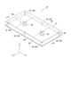
- FIG. 3 is a perspective view of the antenna according to the embodiment.
- FIG. 4 is an exploded perspective view of the antenna according to the embodiment.
- FIG. 5 is a perspective view of the antenna body according to the embodiment.
- FIG. 6 is an exploded perspective view of a part of the antenna body shown in FIG.
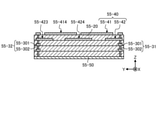
- FIG. 7 is a cross-sectional view of the antenna body shown in FIG. 5 along the line AA.
- FIG. 8 is a plan view schematically showing a current and an electric field when an electromagnetic wave in the first frequency band is radiated.
- FIG. 9 is a cross-sectional view of the state shown in FIG. FIG.
- FIG. 10 is a plan view schematically showing a current and an electric field when an electromagnetic wave in the second frequency band is radiated.
- FIG. 11 is a cross-sectional view of the state shown in FIG.
- FIG. 12 is a plan view schematically showing a current and an electric field when an electromagnetic wave in the third frequency band is radiated.
- FIG. 13 is a cross-sectional view of the state shown in FIG.
- FIG. 14 is a diagram showing the input impedance of the antenna.
- FIG. 15 is a graph showing an example of reflection characteristics with respect to the frequency of the antenna.
- FIG. 16 is a graph showing an example of reflection characteristics with respect to the frequency of the antenna.
- FIG. 17 is a diagram showing a baggage receiving system including the baggage receiving device according to the embodiment.
- FIG. 18A is a front view showing an example of the arrangement of antennas in the baggage receiving device according to the embodiment.
- FIG. 18B is a top view showing an example of the arrangement of antennas in the baggage receiving device according to the embodiment.
- FIG. 18C is a side view showing an example of the arrangement of antennas in the baggage receiving device according to the embodiment.
- FIG. 19 is a schematic diagram showing an example of the relationship between the antenna and the mounting surface according to the embodiment.
- FIG. 20 is a diagram showing an example of a radiation pattern on the radiation surface of the antenna shown in FIG.
- FIG. 21A is a front view showing an example of the baggage receiving device according to the reference example (1).
- FIG. 21B is a top view showing an example of the baggage receiving device according to the reference example (1).
- FIG. 21C is a side view showing an example of the baggage receiving device according to the reference example (1).
- FIG. 22 is a diagram showing an example of the radiation pattern of the dipole antenna according to the reference example (1) shown in FIG. 21.
- FIG. 23A is a front view showing an example of the arrangement of the antenna in the baggage receiving device according to the reference example (2).
- FIG. 23B is a top view showing an example of the arrangement of the antenna in the baggage receiving device according to the reference example (2).
- FIG. 23C is a side view showing an example of the arrangement of the antenna in the baggage receiving device according to the reference example (2).
- FIG. 24 is a diagram showing an example of a radiation pattern on the radiation surface of the antenna of the reference example (2) shown in FIG. 23.
- FIG. 25A is a front view showing an example of the arrangement of antennas in the baggage receiving device according to the reference example (3).
- FIG. 25B is a top view showing an example of the arrangement of the antenna in the baggage receiving device according to the reference example (3).
- FIG. 25C is a side view showing an example of the arrangement of the antenna in the baggage receiving device according to the reference example (3).
- FIG. 26 is a diagram showing an example of the radiation pattern of the antenna of the reference example (3) shown in FIG. 25.
- FIG. 27 is a front view showing another example of mounting the baggage receiving device according to the embodiment.
- FIG. 28 is a front view showing another example of mounting the luggage receiving device according to the embodiment.
- FIG. 29 is a diagram showing another example of the antenna main body according to the embodiment.
- FIG. 30A is a cross-sectional view taken along the line LVIa-LVIa shown in FIG. 29.
- FIG. 30B is a cross-sectional view taken along the line LVIb-LVIb shown in FIG. 29.
- FIG. 31 is a front view showing another example of the arrangement of the antenna in the baggage receiving device according to the embodiment.
- FIG. 32 is a diagram showing another example of the antenna main body shown in FIG. 29.
- FIG. 1 is a perspective view of a baggage receiving device according to an embodiment.
- FIG. 2 is a front view showing a part of the cargo receiving device.
- the package receiving device 100 is a system for receiving and storing the package carried by the delivery company and delivering the stored package to the recipient.
- the luggage includes, for example, mail, home delivery, and the like.
- the package receiving device 100 is, for example, a delivery box having a storage management function.
- the cargo receiving device 100 includes a cargo receiving box 110, a wireless communication module 120, a display unit 125, and a control unit 130.
- the luggage receiving box 110 is formed of a conductor or the like so that the outer shape is square.
- the cargo receiving box 110 has a plurality of storages for storing cargo. Each storage of the luggage receiving box 110 is accessed from the front side by the delivery company to deposit the luggage. Further, each storage of the cargo receiving box 110 is accessed by the recipient, for example, from the front side in order to take out the cargo.
- the wireless communication module 120 is a module capable of bidirectional communication with the outside wirelessly.
- the display unit 125 is provided on the front side of the cargo receiving box 110.
- the display unit 125 is a display device such as a liquid crystal display.
- the control unit 130 comprehensively controls the operation of the cargo receiving device 100 to realize various functions.
- the control unit 130 includes, for example, an integrated circuit such as a CPU (Central Processing Unit).
- the control unit 130 is electrically connected to the wireless communication module 120.
- the control unit 130 wirelessly communicates with the outside via the wireless communication module 120.
- the control unit 130 controls to manage the cargo stored in the cargo receiving box 110.
- the control unit 130 communicates with the outside via the wireless communication module 120 to exchange information for managing luggage.
- the control unit 130 controls the display unit 125 to display a screen that provides information for managing the cargo.
- FIG. 3 is a perspective view of the antenna according to the embodiment.
- FIG. 4 is an exploded perspective view of the antenna according to the embodiment.
- the wireless communication module 120 is provided in front of the luggage receiving box 110.
- the wireless communication module 120 includes an antenna 1 and an RF module 12.
- the antenna 1 includes an antenna main body 10, a housing case 13, and a cover 14.
- the RF module 12 is housed in the housing case 13 and is electrically connected to the antenna body 10.
- FIG. 5 is a perspective view of the antenna body according to the embodiment.
- FIG. 6 is an exploded perspective view of a part of the antenna body shown in FIG.
- FIG. 7 is a cross-sectional view of the antenna body shown in FIG. 5 along the line AA.
- the XYZ coordinate system is adopted.
- the X-axis positive direction and the X-axis negative direction are not particularly distinguished, the X-axis positive direction and the X-axis negative direction are collectively referred to as "X-direction".
- the positive direction of the Y axis and the negative direction of the Y axis are not particularly distinguished, the positive direction of the Y axis and the negative direction of the Y axis are collectively referred to as "Y direction”.
- the Z-axis positive direction and the Z-axis negative direction are not particularly distinguished, the Z-axis positive direction and the Z-axis negative direction are collectively referred to as "Z-direction".
- the antenna main body 10 includes a base 20, a first connecting conductor group 30, a second connecting conductor group 32, a third connecting conductor group 34, a first conductor 40, and a first conductor. Includes two conductors 50 and a feeder line 60.
- the first connecting conductor group 30, the second connecting conductor group 32, the third connecting conductor group 34, the first conductor 40, the second conductor 50 and the feeder line 60 may contain the same conductive material or different conductive materials. May include.
- the "conductive material” may include any of a metal material, an alloy of the metal material, a cured product of the metal paste, and a conductive polymer as a composition.
- Metallic materials include copper, silver, palladium, gold, platinum, aluminum, chromium, nickel, cadmium lead, selenium, manganese, tin, vanadium, lithium, cobalt, titanium and the like. Alloys include multiple metallic materials.
- the metal paste agent includes a powder of a metal material kneaded with an organic solvent and a binder.
- the binder includes an epoxy resin, a polyester resin, a polyimide resin, a polyamide-imide resin, and a polyetherimide resin.
- the conductive polymer includes a polythiophene-based polymer, a polyacetylene-based polymer, a polyaniline-based polymer, a polypyrrole-based polymer, and the like.
- the antenna body 10 can exhibit an artificial magnetic wall characteristic (Artificial Magnetic Conductor Character) with respect to an electromagnetic wave having a predetermined frequency incident on a surface on which the first conductor 40 is located from the outside.
- an artificial magnetic wall characteristic Artificial Magnetic Conductor Character
- the "artificial magnetic wall characteristic” means the characteristic of the surface where the phase difference between the incident wave and the reflected wave at one resonance frequency is 0 degrees.
- the antenna body 10 may have an operating frequency in the vicinity of at least one of at least one resonance frequency.
- the phase difference between the incident wave and the reflected wave becomes smaller than the range from ⁇ 90 degrees to +90 degrees in the operating frequency band.
- the substrate 20 is configured to support the first conductor 40.
- the external shape of the substrate 20 may be a substantially rectangular parallelepiped shape according to the shape of the first conductor 40.
- the substrate 20 may include a dielectric material.
- the relative permittivity of the substrate 20 may be appropriately adjusted according to the desired resonance frequency of the antenna body 10.
- the "dielectric material” may include either a ceramic material or a resin material as a composition.
- Ceramic materials include aluminum oxide sintered body, aluminum nitride sintered body, mulite sintered body, glass-ceramic sintered body, crystallized glass in which crystal components are precipitated in a glass base material, and mica or titanium. Includes microcrystalline sintered body such as aluminum acetate.
- the resin material includes an epoxy resin, a polyester resin, a polyimide resin, a polyamide-imide resin, a polyetherimide resin, and a cured uncured material such as a liquid crystal polymer.
- the substrate 20 has an upper portion 21, a side wall portion 22, and two pillar portions 23.
- the substrate 20 may have one or three or more pillar portions 23 depending on the size of the antenna main body 10 and the like.
- the substrate 20 does not have to have the pillar portion 23 depending on the size of the antenna main body 10 and the like.
- the upper part 21 spreads along the XY plane.
- the upper portion 21 may have a substantially rectangular shape according to the shape of the first conductor 40. However, the upper portion 21 may have any shape as long as it has a shape corresponding to the shape of the first conductor 40.
- the upper portion 21 includes two planes substantially parallel to the XY plane. One of the two surfaces included in the upper portion 21 faces the outside of the substrate 20. The other faces the inside of the substrate 20.
- the side wall portion 22 surrounds the outer peripheral portion of the substantially rectangular upper portion 21.
- the side wall portion 22 is connected to the outer peripheral portion of the upper portion 21.
- the side wall portion 22 extends from the outer peripheral portion of the upper portion 21 toward the second conductor 50 along the Z direction.
- the area surrounded by the upper portion 21 and the side wall portion 22 is a cavity. However, at least a part of the region surrounded by the upper portion 21 and the side wall portion 22 may be filled with a dielectric material or the like.
- the pillar portion 23 is located in the area surrounded by the upper portion 21 and the side wall portion 22.
- the pillar portion 23 is located between the first conductor 40 and the second conductor 50.
- the pillar portion 23 is configured to maintain a distance between the first conductor 40 and the second conductor 50.
- Each of the two pillars 23 may be configured to maintain a distance between the first conductor 40 and the second conductor 50 at different positions from each other.
- the shape of the pillar portion 23 viewed from the Z direction may be cross-shaped.
- the first connecting conductor group 30 includes a plurality of first connecting conductors 31.
- the first connecting conductor group 30 includes two first connecting conductors 31.
- the first connecting conductor group 30 may include an arbitrary number of first connecting conductors 31 depending on, for example, the shape of the first conductor 40.
- the plurality of first connecting conductors 31 are arranged in the X direction.
- the intervals at which the plurality of first connecting conductors 31 are arranged in the X direction may be substantially equal intervals.
- the first connecting conductor 31 may be along the Z direction.
- the first connecting conductor 31 may be a columnar conductor.
- the first connecting conductor 31 is configured such that one end of the first connecting conductor 31 is electrically connected to the first conductor 40 and the other end of the first connecting conductor 31 is electrically connected to the second conductor 50. It may have been done.
- the second connecting conductor group 32 is aligned with the first connecting conductor group 30 in the Y direction.
- the second connecting conductor group 32 includes a plurality of second connecting conductors 33. In the configuration shown in FIG. 6, the second connecting conductor group 32 includes two second connecting conductors 33. However, the second connecting conductor group 32 may include an arbitrary number of second connecting conductors 33, for example, depending on the shape of the first conductor 40 and the like.
- the plurality of second connecting conductors 33 are arranged in the X direction.
- the interval in which the second connecting conductors 33 are arranged in the X direction may be substantially equal to the interval in which the first connecting conductors 31 are arranged in the X direction.
- the second connecting conductor 33 may be along the Z direction.
- the second connecting conductor 33 may be a columnar conductor.
- the second connecting conductor 33 is configured such that one end of the second connecting conductor 33 is electrically connected to the first conductor 40 and the other end of the second connecting conductor 33 is electrically connected to the second conductor 50. It may have been done.
- the third connecting conductor group 34 is aligned with the first connecting conductor group 30 and the second connecting conductor group 32 in the Y direction.
- the third connecting conductor group 34 includes a plurality of third connecting conductors 35. In the configuration shown in FIG. 6, the third connecting conductor group 34 includes two third connecting conductors 35. However, the third connecting conductor group 34 may include an arbitrary number of third connecting conductors 35, for example, depending on the shape of the first conductor 40 and the like.
- the plurality of third connecting conductors 35 are arranged in the X direction.
- the interval in which the third connecting conductor 35 is arranged in the X direction may be substantially equal to at least one of the interval in which the first connecting conductor 31 is arranged in the X direction and the interval in which the second connecting conductor 33 is arranged in the X direction.
- the third connecting conductor 35 may be along the Z direction.
- the third connecting conductor 35 may be a columnar conductor.
- the third connecting conductor 35 is configured such that one end of the third connecting conductor 35 is electrically connected to the first conductor 40 and the other end of the third connecting conductor 35 is electrically connected to the second conductor 50. It may have been done.
- the first conductor 40 is configured to function as a resonator.
- the first conductor 40 extends along the XY plane.
- the first conductor 40 is located on the upper portion 21 of the substrate 20.
- the first conductor 40 may be located on the surface facing the inside of the substrate 20 among the two surfaces substantially parallel to the XY plane included in the upper portion 21.
- the first conductor 40 may be a flat plate-shaped conductor.
- the shape of the first conductor 40 may be substantially rectangular.
- the short side of the substantially rectangular first conductor 40 is along the X direction.
- the long side of the substantially rectangular first conductor 40 is along the Y direction.
- the first conductor 40 includes a third conductor 41-1, a third conductor 41-2, and connecting portions 43a, 43b, 43c, 43d, 43e, 43f. However, the first conductor 40 does not have to include the connecting portions 43a, 43b, 43c, 43d, 43e, 43f.
- third conductor 41 when the third conductor 41-1 and the third conductor 41-2 are not particularly distinguished, these are collectively referred to as "third conductor 41".
- the third conductor 41 and the connecting portions 43a to 43f may contain the same conductive material or may contain different conductive materials.
- the third conductor 41 may have a substantially rectangular shape.
- the third conductor 41 includes four corners.
- the third conductor 41 includes two sides along the X direction and two sides along the Y direction.
- the third conductor 41-1 has a gap 42-1.
- the third conductor 41-2 has a gap 42-2.
- the gap 42 extends from the central portion of one side of the two sides along the Y direction of the third conductor 41 toward the central portion of the other side.
- the gap 42 is along the X direction.
- a part of the pillar portion 23 on the positive direction side of the Z axis may be located in a part near the center of the gap 42 along the X direction.
- the width of the gap 42 may be appropriately adjusted according to the desired operating frequency of the antenna body 10.
- the third conductor 41-1 and the third conductor 41-2 are lined up in the Y direction.
- One side of the third conductor 41-1 along the X direction on the positive side of the Y axis and one side of the third conductor 41-2 along the negative direction of the Y axis are integrated.
- the connecting portions 43a and 43b are located at two corners of the third conductor 41-1 on the negative direction side of the Y axis, respectively.
- the connecting portions 43a and 43b are each configured to be electrically connected to the first connecting conductor 31.
- the shape of the connecting portions 43a and 43b may be a rounded shape corresponding to the first connecting conductor 31.
- the two corner portions on the negative direction side of the Y-axis of the third conductor 41-1 are configured to be electrically directly connected to the first connecting conductor 31. May be done.
- the connecting portion 43c is located near the center of the long side on the positive direction side of the X axis of the two long sides of the first conductor 40.
- the connecting portion 43c is located at the corner portion of the integrated third conductor 41-1 on the Y-axis positive direction side and the corner portion of the third conductor 41-2 on the Y-axis negative direction side on the X-axis positive direction side. do.
- the connecting portion 43c is configured to be electrically connected to the second connecting conductor 33.
- the shape of the connecting portion 43c may be a rounded shape corresponding to the second connecting conductor 33.
- the corner portion of the integrated third conductor 41-1 on the Y-axis positive direction side and the corner portion of the third conductor 41-2 on the Y-axis negative direction side are It may be configured to be electrically directly connected to the second connecting conductor 33.
- the connecting portion 43d is located near the center of the long side on the negative direction side of the X axis of the two long sides of the first conductor 40.
- the connecting portion 43d is located on the negative direction side of the X axis at the corner portion of the integrated third conductor 41-1 on the positive direction side of the Y axis and the corner portion of the third conductor 41-2 on the negative direction side of the Y axis. do.
- the connecting portion 43d is configured to be electrically connected to the second connecting conductor 33.
- the shape of the connecting portion 43d may be a rounded shape corresponding to the second connecting conductor 33.
- the corner portion of the integrated third conductor 41-1 on the Y-axis positive direction side and the corner portion of the third conductor 41-2 on the Y-axis negative direction side are It may be configured to be electrically directly connected to the second connecting conductor 33.
- the connecting portions 43e and 43f are located at two corners on the Y-axis positive direction side of the third conductor 41-2, respectively.
- the connecting portions 43e and 43f are each configured to be electrically connected to the third connecting conductor 35.
- the shapes of the connecting portions 43e and 43f may be rounded according to the third connecting conductor 35.
- the two corner portions on the Y-axis positive direction side of the third conductor 41-2 are configured to be electrically directly connected to the third connecting conductor 35. It may have been done.
- the first conductor 40 is configured to capacitively connect the first connecting conductor group 30 and the second connecting conductor group 32.
- the third conductor 41-1 is configured to be electrically connected to the first connecting conductor 31 by the connecting portions 43a and 43b and electrically connected to the second connecting conductor 33 by the connecting portions 43c and 43d. ing.
- the first connecting conductor 31 and the second connecting conductor 33 may be capacitively connected via the gap 42-1 of the third conductor 41-1.
- the first conductor 40 is configured to capacitively connect the second connecting conductor group 32 and the third connecting conductor group 34.
- the third conductor 41-2 is configured to be electrically connected to the second connecting conductor 33 by the connecting portions 43c and 43d, and electrically connected to the third connecting conductor 35 by the connecting portions 43e and 43f. ing.
- the second connecting conductor 33 and the third connecting conductor 35 can be capacitively connected via the gap 42-2 of the third conductor 41-2.
- the first conductor 40 is configured to capacitively connect the first connecting conductor group 30 and the third connecting conductor group 34.
- the third conductor 41-1 is electrically connected to the first connecting conductor 31 by the connecting portions 43a and 43b.
- the third conductor 41-2 is configured to be electrically connected to the third connecting conductor 35 by the connecting portions 43e and 43f.
- the first connecting conductor group 30 and the third connecting conductor group 34 can be capacitively connected via the gap 42-1 of the third conductor 41-1 and the gap 42-2 of the third conductor 41-2. ..
- the second conductor 50 is configured to provide a reference potential in the antenna body 10.
- the second conductor 50 may be configured to be electrically connected to the ground of the device including the antenna body 10. As shown in FIG. 7, the second conductor 50 is located on the negative side of the Z-axis of the substrate 20. Various components of the device including the antenna body 10 may be located on the negative side of the second conductor 50 on the Z axis.
- the antenna body 10 can maintain the radiation efficiency at the operating frequency by having the above-mentioned artificial magnetic wall characteristics even when the various parts are located on the Z-axis negative direction side of the second conductor 50.
- the second conductor 50 extends along the XY plane.
- the second conductor 50 may be a flat plate-shaped conductor.
- the second conductor 50 is separated from the first conductor 40 in the Z direction.
- the second conductor 50 may face the first conductor 40.
- the second conductor 50 may have a substantially rectangular shape according to the shape of the first conductor 40. However, the second conductor 50 may have any shape according to the shape of the first conductor 40.
- the short side of the substantially rectangular second conductor 50 is along the X direction.
- the long side of the substantially rectangular second conductor 50 is along the Y direction.
- the second conductor 50 may have an opening 50A depending on the structure of the feeder line 60.
- the second conductor 50 includes the fourth conductor 51-1 and the fourth conductor 51-2.
- fourth conductor 51-1 and the fourth conductor 51-2 are collectively referred to as "fourth conductor 51".
- the fourth conductor 51 may have a substantially rectangular shape.
- the substantially rectangular fourth conductor 51 includes four corners.
- the fourth conductor 51-1 faces the third conductor 41-1.
- the fourth conductor 51-2 faces the third conductor 41-2.
- One side of the fourth conductor 51-1 along the X direction on the positive side of the Y axis and one side of the fourth conductor 51-2 along the negative direction of the Y axis are integrated.
- the second conductor 50 is configured to be electrically connected to the first connecting conductor group 30.
- the two corners on the negative direction side of the Y-axis are configured to be electrically connected to the first connecting conductor 31, respectively.
- the second conductor 50 is configured to be electrically connected to the second connecting conductor group 32.
- the corners of the integrated fourth conductor 51-1 on the positive Y-axis side and the negative side of the fourth conductor 51-2 on the negative Y-axis side are configured so that the second connecting conductor 33 is electrically connected.
- the second conductor 50 is configured to be electrically connected to the third connecting conductor group 34.
- the two corners on the positive direction side of the Y-axis are each configured so that the third connecting conductor 35 is electrically connected.
- a part of the feeder line 60 is along the Z direction.
- the feeder line 60 may be a columnar conductor.
- a portion of the feeder line 60 may be located in the area surrounded by the upper portion 21 and the side wall portion 22.
- the feeder line 60 is configured to be electromagnetically connected to the first conductor 40.
- the "electromagnetic connection” may be an electrical connection or a magnetic connection.
- one end of the feeder line 60 may be configured to be electrically connected to the first conductor 40.
- the other end of the feeder line 60 may extend to the outside from the opening 50A of the second conductor 50 shown in FIG.
- the other end of the feeder line 60 may be configured to be electrically connected to an external device or the like.
- the feeder line 60 is configured to supply electric power to the first conductor 40.
- the feeder line 60 is configured to supply electric power from the first conductor 40 to an external device or the like.
- FIG. 8 is a plan view schematically showing the currents L1 and L2 and the electric field E when the electromagnetic wave of the first frequency band is radiated.
- FIG. 8 shows the direction of the electric field E as seen from the positive direction side of the Z axis at a certain moment.
- the solid currents L1 and L2 indicate the direction of the current flowing through the first conductor 40 as viewed from the positive direction side of the Z axis at a certain moment.
- the broken lines currents L1 and L2 indicate the direction of the current flowing through the second conductor 50 as viewed from the positive direction side of the Z axis at a certain moment.
- FIG. 9 is a cross-sectional view of the state shown in FIG.
- the current L1 and the current L2 can be excited by appropriately supplying electric power from the feeder line 60 to the first conductor 40.
- the antenna body 10 is configured to radiate an electromagnetic wave in the first frequency band by the current L1 and the current L2.
- the first frequency band is one of the operating frequency bands of the antenna body 10.
- the current L1 can be a loop current flowing along the first loop.
- the first loop may include a first connecting conductor group 30, a second connecting conductor group 32, a first conductor 40, and a second conductor 50.
- the first loop may include a first connecting conductor 31, a second connecting conductor 33, a third conductor 41-1 and a fourth conductor 51-1.
- the current L2 can be a loop current flowing along the second loop.
- the second loop may include a second connecting conductor group 32, a third connecting conductor group 34, a first conductor 40, and a second conductor 50.
- the second loop may include a second connecting conductor 33, a third connecting conductor 35, a third conductor 41-2, and a fourth conductor 51-2.
- the direction of the current L1 flowing through the corresponding portions in the first loop and the second loop and the direction of the current L2 can be the same.
- the second connecting conductor 33 included in the first loop and the third connecting conductor 35 included in the second loop are corresponding portions.
- the direction of the current L1 flowing through the second connecting conductor 33 included in the first loop and the direction of the current L2 flowing through the third connecting conductor 35 included in the second loop are different. It can be in the same negative direction on the Z axis.
- the first connecting conductor 31 included in the first loop and the second connecting conductor 33 included in the second loop are corresponding portions.
- the direction of the current L1 flowing through the first connecting conductor 31 included in the first loop and the direction of the current L2 flowing through the second connecting conductor 33 included in the second loop may be the same Z-axis positive direction.
- the direction of the current L1 flowing through the corresponding portions in the first loop and the second loop is the same as the direction of the current L2, so that the direction of the current L1 flowing through the second connecting conductor 33 of the first loop and the first
- the direction of the current L2 flowing through the second connecting conductor 33 of the two loops may be opposite to that of the current L2.
- Z axis can be in the positive direction.
- the direction of the electric field near the second connecting conductor group 32 generated by the current L1 and the current can be opposite to that of the electric field.
- the electric field near the second connecting conductor group 32 generated by the current L1 and the electric field near the second connecting conductor group 32 generated by the current L2 are viewed macroscopically. , Can be offset.
- the current L1 and the current L2 can be regarded as one macroscopic loop current.
- This macroscopic loop current can be considered to flow along a loop that includes a first connecting conductor group 30, a third connecting conductor group 34, a first conductor 40, and a second conductor 50.
- the direction of the electric field near the first connecting conductor group 30 generated by this macroscopic loop current and the direction of the electric field near the third connecting conductor group 34 generated by this macroscopic loop current can be opposite. For example, as shown in FIG. 8, when the direction of the electric field near the first connecting conductor group 30 is the Z-axis positive direction, the direction of the electric field near the third connecting conductor group 34 can be the Z-axis negative direction.
- the first connecting conductor group 30 and the third connecting conductor group 34 can function as a pair of electric conductors when viewed from the first conductor 40 as a resonator.
- the YZ plane on the positive direction side of the X axis and the YZ plane on the negative direction side of the X axis can function as a pair of magnetic walls when viewed from the first conductor 40 as a resonator. ..
- the antenna body 10 artificially receives electromagnetic waves in the first frequency band incident on the first conductor 40 from the outside. This is the mode (first mode) that shows the magnetic wall characteristics.
- FIG. 10 is a plan view schematically showing the currents L3 and L4 and the electric field E when the electromagnetic wave in the second frequency band is radiated.
- FIG. 10 shows the direction of the electric field E as seen from the positive direction side of the Z axis at a certain moment.
- the solid currents L3 and L4 indicate the direction of the current flowing through the first conductor 40 as viewed from the positive direction side of the Z axis at a certain moment.
- the broken lines currents L3 and L4 indicate the direction of the current flowing through the second conductor 50 as viewed from the positive direction side of the Z axis at a certain moment.
- FIG. 11 is a cross-sectional view of the state shown in FIG.
- the current L3 and the current L4 can be excited in the second frequency band by appropriately supplying electric power from the feeder line 60 to the first conductor 40.
- the second frequency band can be one of the operating frequency bands of the antenna body 10. The frequency belonging to the second frequency band is higher than the frequency belonging to the first frequency band.
- the current L3 can flow the third conductor 41-1 from the vicinity of the center of the third conductor 41-1 toward each of the four corners of the third conductor 41-1.
- the current L3 may allow the third conductor 41-1 to flow from each of the four corners of the third conductor 41-1 towards the center of the third conductor 41-1.
- the current L3 can flow the fourth conductor 51-1 from each of the four corners of the fourth conductor 51-1 toward the vicinity of the center of the fourth conductor 51-1.
- the current L3 may flow the fourth conductor 51-1 from near the center of the fourth conductor 51-1 toward each of the four corners of the fourth conductor 51-1.
- the direction of the current L3 flowing through the first connecting conductor 31 and the direction of the current L3 flowing through the second connecting conductor 33 can be the same direction.
- the direction of the current L3 flowing through the second connecting conductor 33 is the negative direction of the Z axis. Can be.
- the direction of the current L3 flowing through the second connecting conductor 33 may be the Z-axis positive direction.
- the third conductor 41-1, the fourth conductor 51-1, the first connecting conductor 31, and the second connecting conductor 33 may form a first dielectric resonator.
- the first dielectric resonator can resonate in the TM (Transverse Magnetic) mode (second mode), which is the resonance mode of the dielectric resonator, when the current L3 is excited.
- the current L4 can flow the third conductor 41-2 from the vicinity of the center of the third conductor 41-2 toward each of the four corners of the third conductor 41-2.
- the current L4 may allow the third conductor 41-2 to flow from each of the four corners of the third conductor 41-2 toward the vicinity of the center of the third conductor 41-2.
- the current L4 can flow the fourth conductor 51-2 from each of the four corners of the fourth conductor 51-2 toward the vicinity of the center of the fourth conductor 51-2. At another moment, the current L4 may flow the fourth conductor 51-2 from near the center of the fourth conductor 51-2 toward each of the four corners of the fourth conductor 51-2.
- the direction of the current L4 flowing through the second connecting conductor 33 and the direction of the current L4 flowing through the third connecting conductor 35 can be the same direction.
- the direction of the current L4 flowing through the third connecting conductor 35 is the negative direction of the Z axis. Can be.
- the direction of the current L4 flowing through the third connecting conductor 35 may be the Z-axis positive direction.
- the third conductor 41-2, the fourth conductor 51-2, the second connecting conductor 33, and the third connecting conductor 35 can form a second dielectric resonator.
- the second dielectric resonator can resonate in the TM mode, which is the resonance mode of the dielectric resonator, by exciting the current L4.
- the direction of the current flowing through the first connecting conductor group 30, the direction of the current flowing through the second connecting conductor group 32, and the direction of the current flowing through the third connecting conductor group 34 are the same.
- the direction of the current L3 flowing through the first connecting conductor 31 and the second connecting conductor 33 and the direction of the current L4 flowing through the second connecting conductor 33 and the third connecting conductor 35 can be the same.
- the direction of the electric field on the third conductor 41-1 generated by the current L3 and the direction of the electric field on the third conductor 41-2 generated by the current L4 are in the same direction. Can be.
- the antenna body 10 is configured to act as a dielectric resonator antenna in the second frequency band.
- the first dielectric resonator and the second dielectric resonator can resonate in the TM mode of the dielectric resonators having the same phase as each other.
- FIG. 12 is a plan view schematically showing the currents L5 and L6 and the electric field E when the electromagnetic wave of the third frequency band is radiated.
- FIG. 12 shows the direction of the electric field E as seen from the positive direction side of the Z axis at a certain moment.
- the solid currents L5 and L6 indicate the direction of the current flowing through the first conductor 40 as viewed from the positive direction side of the Z axis at a certain moment.
- the broken lines currents L5 and L6 indicate the direction of the current flowing through the second conductor 50 as viewed from the positive direction side of the Z axis at a certain moment.
- FIG. 13 is a cross-sectional view of the state shown in FIG.
- the current L5 and the current L6 can be excited in the third frequency band by appropriately supplying electric power from the feeder line 60 to the first conductor 40.
- the third frequency band is one of the operating frequency bands of the antenna body 10.
- the frequency belonging to the third frequency band is higher than the frequency belonging to the first frequency band.
- the third frequency band may be higher than the second frequency band depending on the configuration of the antenna body 10 and the like.
- the current L5 can flow through the third conductor 41-1, the fourth conductor 51-1, the first connecting conductor 31, and the second connecting conductor 33, similar to the current L3 shown in FIG.
- the first dielectric resonator can resonate in the TM mode, which is the resonance mode of the dielectric resonator, by exciting the current L5.
- the current L6 can flow through the third conductor 41-2, the fourth conductor 51-2, the second connecting conductor 33, and the third connecting conductor 35, similar to the current L4 shown in FIG. However, the direction of the current L6 flowing through the second connecting conductor 33 and the third connecting conductor 35 is opposite to the direction of the current L5 flowing through the first connecting conductor 31 and the second connecting conductor 33.
- the second dielectric resonator can resonate in the TM mode having a phase opposite to that of the first dielectric resonator by exciting the current L6.
- the antenna body 10 is configured to radiate an electromagnetic wave in the third frequency band by causing the direction of the current flowing through the first connecting conductor group 30 and the direction of the current flowing through the third connecting conductor group 34 to be opposite to each other.
- the direction of the current L5 flowing through the first connecting conductor 31 and the second connecting conductor 33 and the direction of the current flowing through the second connecting conductor 33 and the third connecting conductor 35 may be opposite to each other.
- the direction of the electric field on the third conductor 41-1 generated by the current L5 and the direction of the electric field on the third conductor 41-2 generated by the current L6 can be opposite to each other.
- the antenna body 10 is configured to act as a dielectric resonator antenna in the third frequency band.
- the first dielectric resonator and the second dielectric resonator can resonate in the TM mode of the dielectric resonators having opposite phases to each other.
- the storage case 13 is made of metal.
- the metal may be iron or stainless steel, and is not particularly limited.
- the storage case 13 has a bottom plate 71, a side wall 72, and a flange 73.
- the storage case 13 is formed in a box shape having an opening.
- the opening of the housing case 13 is formed on the surface side where the first conductor 40 of the antenna body 10 is located. That is, the opening of the accommodation case 13 is formed on the surface on the side where the electromagnetic wave enters and exits.
- the antenna body 10 is installed on the bottom plate 71.
- the bottom plate 71 is formed in a substantially rectangular shape according to the shape of the antenna main body 10.
- the bottom plate 71 may have any shape as long as it has a shape corresponding to the shape of the antenna main body 10.
- the side wall 72 is erected from the bottom plate 71 and is provided at a distance around the antenna main body 10.
- the side walls 72 are provided on all sides according to the substantially rectangular bottom plate 71, and the side walls 72 on each side are arranged in a frame shape. It is sufficient that at least one side wall 72 is provided. Further, the side wall 72 is not particularly limited to being provided in a frame shape on all sides, and may be formed in a cylindrical shape surrounding the periphery of the antenna main body 10.
- the flange 73 is provided on the opening side of the side wall 72, and is provided from the side wall 72 toward the outside.
- the flange 73 is formed in a flat plate shape and has an opening at the center.
- a cover 14 is attached to the flange 73.
- the distance D between the antenna main body 10 and the side wall 72 in the X direction and the Y direction is ⁇ / 8 or more, where ⁇ is the wavelength of the electromagnetic wave transmitted / received in the antenna main body 10. More preferably, the distance between the antenna body 10 and the side wall 72 in the X and Y directions is ⁇ / 4.
- the electromagnetic wave is a frequency band for transmission and reception in the TM mode, for example, a 2 GHz band.
- the wavelength ⁇ of the electromagnetic wave having a center frequency in the 2 GHz band is, for example, approximately 16 cm. Therefore, ⁇ / 4, which is the distance between the antenna main body 10 and the side wall 72, is approximately 40 mm.
- the cover 14 closes the opening of the storage case 13.
- the cover 14 is made of a material containing resin and is formed in a flat plate shape.
- the cover 14 is fixed to the flange 73 by a fastening member such as a screw.
- the RF module 12 is arranged in the corner of the storage case 13.
- the RF module 12 may be configured to control the power supplied to the antenna body 10.
- the RF module 12 is configured to modulate the baseband signal and supply it to the antenna body 10.
- the RF module 12 may be configured to modulate the electrical signal received by the antenna body 10 into a baseband signal.
- the wireless communication module 120 is provided so that the opening side surface of the storage case 13 is in front of the cargo receiving box 110. Therefore, the wireless communication module 120 can transmit and receive electromagnetic waves on the front side, which is the open space side.
- the wireless communication module 120 may be provided so that the opening side surface of the storage case 13 is the top surface of the luggage receiving box 110.
- FIG. 14 is a diagram showing the input impedance of the antenna.
- FIG. 14 is a so-called Smith chart.
- I1 is the input impedance of the antenna 1 not housed in the housing case 13
- I2 is the input impedance of the antenna 1 housed in the housing case 13 of the present disclosure.
- I2 has a smaller input impedance locus than I1. For example, when comparing I1 and I2 when the frequency of the electromagnetic wave is 2.0 GHz, the input impedance of I1 is smaller. Comparing I1 and I2 when the frequency of the electromagnetic wave is 1.6 GHz, the input impedances are almost the same.
- FIG. 15 is a graph showing an example of reflection characteristics with respect to the frequency of the antenna.
- the horizontal axis is the frequency of the electromagnetic wave
- the vertical axis is the reflection coefficient.
- P1 is the reflectance coefficient of the antenna 1 not housed in the housing case 13
- P2 is the reflectance coefficient of the antenna 1 housed in the housing case 13 of the present disclosure.
- the frequency band in which the reflection coefficient is lower than ⁇ 5 (dB) becomes the frequency band F1 in P1 and the frequency band F2 in P2. Comparing the frequency band F1 and the frequency band F2, the frequency band F2 has a wider band.
- FIG. 16 is a graph showing an example of reflection characteristics with respect to the frequency of the antenna.
- the horizontal axis thereof is the frequency of the electromagnetic wave
- the vertical axis thereof is the reflection coefficient.
- P3 is the reflectance coefficient of the antenna 1 housed in the containment case 13 of the present disclosure and is not blocked by the cover 14, and P4 is housed in the containment case 13 of the present disclosure. It is the reflection coefficient of the antenna 1 which is the antenna 1 and is blocked by the cover 14.
- the frequency band in which the reflection coefficient is lower than ⁇ 2 (dB) becomes the frequency band F3 in P3 and the frequency band F4 in P4. Comparing the frequency band F3 and the frequency band F4, the frequency band F4 has a wider band.
- FIG. 17 is a diagram showing a baggage receiving system including the baggage receiving device according to the embodiment.
- the luggage receiving system 200 includes a luggage receiving device 100 and a communication device 220.
- the communication device 220 receives information transmitted from the baggage receiving device 100 via the wireless communication module 120.
- the communication device 220 may directly communicate wirelessly with the baggage receiving device, or may communicate via a wireless base station or the like.
- the communication device 220 does not have to have a wireless communication function.
- the communication device 220 may be, for example, a server or the like.
- the communication device 220 may exist on a cloud in which a plurality of servers and the like are connected.
- the communication device 220 is managed, for example, by a service provider that operates the system.
- the baggage receiving system 200 may include a wireless communication device 240.
- the wireless communication device 240 receives information about the baggage receiving device 100.
- the wireless communication device 240 may provide information about the baggage receiving device 100.
- the wireless communication device 240 may be a wireless communication device for a delivery company.
- the wireless communication device 240 can receive information about the cargo contained in the baggage receiving device 100.
- the wireless communication device 240 may provide information about the cargo stored by the baggage receiving device 100.
- the wireless communication device 240 may be a wireless communication device for the recipient.
- the radio communication device 240 may include a radio communication device for one or more carriers and a radio communication device for one or more recipients.
- the wireless communication device 240 may be a communication device 220.
- the wireless communication device 240 may directly communicate wirelessly with the recipient of the package.
- the antenna 1 needs to radiate an electromagnetic wave in the extending direction of the corridor to communicate with an outdoor or indoor spot.
- the antenna 1 of the baggage receiving box 110 interferes due to the reflection of electromagnetic waves on an adjacent wall or the like, the electromagnetic waves may become unstable due to the interference. Therefore, in the baggage receiving device 100 according to the embodiment, it is desired to mount the antenna 1 so as to enhance the radiation characteristic of the antenna 1.
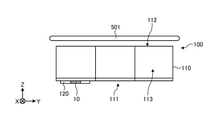
- FIG. 18A is a front view showing an example of the arrangement of the antenna 1 in the baggage receiving device 100 according to the embodiment.
- FIG. 18B is a top view showing an example of the arrangement of the antenna 1 in the baggage receiving device 100 according to the embodiment.
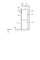
- FIG. 18C is a side view showing an example of the arrangement of the antenna 1 in the baggage receiving device 100 according to the embodiment.
- the cargo receiving device 100 includes a cargo receiving box 110, a wireless communication module 120, and a display unit 125.
- the luggage receiving box 110 is mounted, for example, on a mounting surface 400 parallel to the Y direction and the Z direction.
- the luggage receiving box 110 is directly placed on the mounting surface 400.
- the mounting surface 400 includes, for example, a substantially planar object below the antenna 1 in the transmission space provided with the antenna 1.
- the mounting surface 400 includes, for example, an indoor floor, the ground, and the like.
- the mounting surface 400 includes, for example, a plane on which the luggage receiving box 110 can be placed, a virtual plane on which the luggage receiving box 110 is placed, a gentle slope, and the like.
- the luggage receiving box 110 is an example of a housing that is a conductor.
- the package receiving box 110 is placed on the mounting surface 400 so that, for example, the delivery company, the recipient, and the like can access it from the front 111.
- the luggage receiving box 110 is mounted on the mounting surface 400, for example, so that the back surface 112 is adjacent to the wall 501 of the mounting location.
- the luggage receiving box 110 is placed on the mounting surface 400 so that the upper surface 113 faces the ceiling 502 of the mounting location, for example.
- the upper surface 113 of the luggage receiving box 110 differs depending on the environment in which it is placed, and the upper surface 113 may be placed so as to be adjacent to the ceiling 502, or the upper surface 113 may be placed apart from the ceiling 502. be able to.
- the wireless communication module 120 includes the above-mentioned antenna 1.
- FIG. 19 is a schematic diagram showing an example of the relationship between the antenna 1 and the mounting surface 400 according to the embodiment.
- the antenna body 10 of the antenna 1 in the antenna body 10 of the antenna 1, the current directions of the currents L1 and L2 in the mode showing the artificial magnetic wall characteristic (first mode) are parallel to the mounting surface 400. It is supported by the luggage receiving box 110 (housing).
- the antenna body 10 is supported by the luggage receiving box 110 so that the direction of the current excited when radiating the electromagnetic wave in the first mode is along the mounting surface 400.
- the antenna body 10 is supported by the luggage receiving box 110 so that the first loop and the second loop described above are parallel to the mounting surface 400.
- the fact that the current direction is parallel to the mounting surface 400 means that, for example, the current direction and the mounting surface 400 are parallel, and the angle between the current direction and the mounting surface 400 is smaller than 45 degrees. Including crossing. That is, the antenna 1 may be supported by the luggage receiving box 110 (housing) so that, for example, the angle formed by the mounting surface 400 and the current direction intersects at an angle smaller than 45 degrees.
- the antenna 1 is arranged on the front 111 of the luggage receiving box 110
- the present invention is not limited to this.
- the antenna 1 may be arranged on the side surface of the luggage receiving box 110 or the like.
- FIG. 20 is a diagram showing an example of a radiation pattern on the radiation surface of the antenna 1 shown in FIG.
- the radiation pattern shown in FIG. 20 shows the radiation patterns in the front direction and the back direction in the YZ plane of the antenna body 10.
- the front direction includes a direction from the antenna main body 10 toward the front of the front 111 of the luggage receiving box 110.
- the rearward direction includes a direction from the antenna body 10 toward the backside 112 of the luggage receiving box 110.
- the antenna 1 has a gain (gain) in the front direction of ⁇ 0.4 (dB) when the current directions of the currents L1 and L2 in the first mode are parallel to the mounting surface 400.
- a characteristic with a gain in the back direction of -7.4 (dB) can be obtained. That is, the antenna 1 shows that the gain in the front direction is higher than the gain in the back direction when the current directions of the currents L1 and L2 in the first mode are parallel to the mounting surface 400. ..
- the antenna 1 has a radiation pattern having a higher gain than the conventional arrangement on the plane in the front direction of the luggage receiving box 110, and good communication with surrounding base stations and the like is possible. Further, since the antenna 1 suppresses radiation to the back surface 112 of the luggage receiving box 110, there is no interference with the reflected wave from the wall 501, and stable communication can be enabled.
- FIG. 21A is a front view showing an example of the baggage receiving device according to the reference example (1).
- FIG. 21B is a top view showing an example of the baggage receiving device according to the reference example (1).
- FIG. 21C is a side view showing an example of the baggage receiving device according to the reference example (1).
- the cargo receiving device 600 includes a cargo receiving box 110, a wireless communication module 120, and a display unit 125. As described above, the luggage receiving box 110 is mounted on the mounting surface 400.
- the baggage receiving device 600 includes a dipole antenna 610 instead of the above-mentioned antenna 1.
- the dipole antenna 610 is, for example, an antenna having an isotropic radiation pattern.
- the dipole antenna 610 is provided on the upper surface 113 so as to project from the upper surface 113 of the luggage receiving box 110 toward the ceiling 502.
- the dipole antenna 610 is provided on the upper surface 113 of the luggage receiving box 110 so that the tip end portion is located in the vicinity of the ceiling 502.
- the dipole antenna 610 is included in the wireless communication module 120.
- the dipole antenna 610 is electrically connected to the above-mentioned control unit 130.
- FIG. 22 is a diagram showing an example of the radiation pattern of the dipole antenna 610 according to the reference example (1) shown in FIG. 21.
- the radiation pattern shown in FIG. 22 shows the radiation pattern in the front direction and the back direction in the YZ plane of the dipole antenna 610.
- the front direction includes a direction from the dipole antenna 610 toward the front of the front 111 of the luggage receiving box 110.
- the rearward direction includes a direction from the dipole antenna 610 toward the backside 112 of the luggage receiving box 110.
- the dipole antenna 610 when the dipole antenna 610 radiates an electromagnetic wave, the measurement results were obtained with a gain in the front direction of -2.3 (dB) and a gain in the rear direction of -1.5 (dB). .. That is, the dipole antenna 610 has a large gain toward the back surface of the wall 501, and the interference with the reflected wave from the wall 501 may have an adverse effect.
- the dipole antenna 610 shows that the gain in the front direction is low as compared with the radiation pattern of the antenna 1 according to the embodiment shown in FIG.
- FIG. 23A is a front view showing an example of the arrangement of the antenna 1 in the baggage receiving device 100 according to the reference example (2).
- FIG. 23B is a top view showing an example of the arrangement of the antenna 1 in the baggage receiving device 100 according to the reference example (2).
- FIG. 23C is a side view showing an example of the arrangement of the antenna 1 of the baggage receiving device 100 according to the reference example (2).
- the cargo receiving device 100 includes a cargo receiving box 110, a wireless communication module 120, and a display unit 125.
- the luggage receiving box 110 is mounted on the mounting surface 400 parallel to the Y-axis direction and the Z-axis direction.
- the wireless communication module 120 includes the antenna 1 according to the above-described embodiment.
- the antenna body 10 of the antenna 1 has a luggage receiving box 110 (housing) so that the current directions of the currents L1 and L2 in the mode showing the artificial magnetic wall characteristic (first mode) intersect with the mounting surface 400. ) Is supported.
- the antenna body 10 is supported by the luggage receiving box 110 so that the direction of the current excited when radiating the electromagnetic wave in the first mode is along the X-axis direction and perpendicular to the mounting surface 400.
- the antenna main body 10 is supported by the luggage receiving box 110 so that the direction of the current excited when radiating the electromagnetic wave in the first mode does not follow the mounting surface 400.
- FIG. 24 is a diagram showing an example of a radiation pattern on the radiation surface of the antenna 1 of the reference example (2) shown in FIG. 23.
- the radiation pattern shown in FIG. 24 shows the radiation patterns in the front direction and the back direction in the YZ plane of the antenna body 10.
- the front direction includes a direction from the antenna main body 10 toward the front of the front 111 of the luggage receiving box 110.
- the rearward direction includes a direction from the antenna body 10 toward the backside 112 of the luggage receiving box 110.
- the antenna 1 according to the reference example (2) has a gain in the front direction of -2 when the current directions of the currents L1 and L2 in the first mode are perpendicular to the mounting surface 400.
- the measurement results of 0 (dB) and the gain in the back direction of ⁇ 8.3 (dB) were obtained. That is, the antenna 1 according to the reference example (2) radiates the antenna 1 according to the embodiment shown in FIG. 20 when the current directions of the currents L1 and L2 in the first mode are perpendicular to the mounting surface 400. Compared with the pattern, it shows that the gain in the front direction is low.
- FIG. 25A is a front view showing an example of the arrangement of the antenna 1 in the baggage receiving device 100 according to the reference example (3).
- FIG. 25B is a top view showing an example of the arrangement of the antenna 1 in the baggage receiving device 100 according to the reference example (3).
- FIG. 25C is a side view showing an example of the arrangement of the antenna 1 of the baggage receiving device 100 according to the reference example (3).
- the cargo receiving device 100 includes a cargo receiving box 110, a wireless communication module 120, and a display unit 125.
- the luggage receiving box 110 is mounted on the mounting surface 400 parallel to the Y-axis direction and the Z-axis direction.
- the wireless communication module 120 is arranged on the upper surface 113 of the luggage receiving box 110.
- the wireless communication module 120 includes the above-mentioned antenna 1.
- the antenna body 10 of the antenna 1 has a baggage receiving box 110 (so that the current directions of the currents L1 and L2 in the mode showing the artificial magnetic wall characteristic (first mode) are parallel to the mounting surface 400. It is supported by the housing).
- the antenna body 10 according to the reference example (3) is supported by the luggage receiving box 110 so that the direction of the current excited when radiating the electromagnetic wave in the first mode is parallel to the mounting surface 400. .. That is, the antenna body 10 is supported by the cargo receiving box 110 so as to radiate electromagnetic waves toward the ceiling 502 above the luggage receiving box 110, not toward the front of the luggage receiving box 110.
- FIG. 26 is a diagram showing an example of the radiation pattern of the antenna 1 of the reference example (3) shown in FIG. 25.
- the radiation pattern shown in FIG. 26 shows the radiation patterns in the front direction and the back direction in the YZ plane of the antenna body 10 provided on the upper surface 113 of the cargo receiving box 110.
- the front direction includes a direction from the antenna main body 10 toward the front of the front 111 of the luggage receiving box 110.
- the rearward direction includes a direction from the antenna body 10 toward the backside 112 of the luggage receiving box 110.
- the antenna 1 according to the reference example (3) has a gain in the front direction of ⁇ 5 when the current directions of the currents L1 and L2 in the first mode are parallel to the mounting surface 400.
- a measurement result of 3 (dB) and a gain in the back direction of -5.2 (dB) was obtained. That is, the antenna 1 according to the reference example (3) is the antenna 1 according to the embodiment shown in FIG. 20, even if the current directions of the currents L1 and L2 in the first mode are parallel to the mounting surface 400. Compared with the radiation pattern, it shows that the gain in the front direction is low.
- the antenna 1 is supported by the luggage receiving box 110 so that the current directions of the currents L1 and L2 in the first mode are parallel to the mounting surface 400, thereby receiving the luggage.
- the gain of the electromagnetic wave with respect to the front surface direction of the box 110 can be improved.
- the antenna 1 can suppress the radiation of the electromagnetic wave toward the back surface of the luggage receiving box 110, there is no interference of the reflected wave from the wall or the like, and stable communication becomes possible.
- the antenna 1 has a radiation pattern directed toward the front surface of the luggage receiving box 110, and can enable good communication.
- the baggage receiving box 110 can be supported so that the direction of the current excited when the antenna body 10 radiates the electromagnetic wave in the first mode is along the mounting surface 400. ..
- the antenna 1 can obtain a gain of a radiation pattern suitable for communication even in an environment where an open portion such as an entrance / exit is provided on the front side of the luggage receiving box 110.
- the antenna 1 since the luggage receiving box 110 (housing) is a conductor, even if the antenna main body 10 is arranged on the front 111 of the luggage receiving box 110, radiation having a high gain in the front direction is obtained. You can get a pattern. As a result, the antenna 1 can enable good communication with a base station or the like outside the baggage receiving box 110.
- the input impedance of the antenna main body 10 can be reduced by accommodating the antenna main body 10 in the metal storage case 13 having the bottom plate 71 and the side wall 72.
- the wide band of the antenna body 10 can be increased.
- the input impedance of the antenna main body 10 is appropriately reduced by setting the distance between the antenna main body 10 and the side wall 72 to ⁇ / 8 or more, more preferably ⁇ / 4.
- the wide band of the antenna main body 10 can be appropriately increased.
- the antenna main body 10 can be further widened by providing the resin cover 14 that closes the opening of the accommodation case 13.
- wireless communication can be performed using the antenna 1 having high antenna efficiency.
- the wireless communication module 120 by using the wireless communication module 120, it is possible to preferably wirelessly communicate with the outside.
- the surface on the opening side of the antenna 1 of the wireless communication module 120 can be the front surface of the baggage receiving box 110. Therefore, since electromagnetic waves can be transmitted and received on the open space side, it is possible to suppress the occurrence of communication failure due to the radio wave shield.
- various information can be transmitted / received between the baggage receiving device 100 and the communication device 220, and the baggage receiving device 100 and the wireless communication device 240.
- the cargo receiving device 100 is configured to directly mount the cargo receiving box 110 (housing) on the mounting surface 400
- the present invention is not limited to this.
- the cargo receiving device 100 may be configured to mount the cargo receiving box 110 (housing) on the mounting surface 400 via a mounting member.
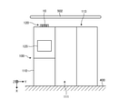
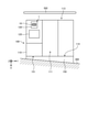
- 27 and 28 are front views showing another example of mounting of the baggage receiving device 100 according to the embodiment.
- the luggage receiving box 110 is mounted on the mounting surface 400 via the pedestal 140.
- the mounting surface 400 is, for example, a horizontal floor, the ground, or the like.
- the pedestal 140 is an example of a mounting member.
- the pedestal 140 includes, for example, a base, a plurality of legs, and the like.
- the pedestal 140 is provided on the mounting surface 400 so that the upper surface 141 is parallel to the mounting surface 400.
- the luggage receiving box 110 is provided on the upper surface 141 of the pedestal 140 so that the lower surface 114 faces the mounting surface 400, for example.
- the luggage receiving box 110 is placed on the mounting surface 400 so that the upper surface 113 faces the ceiling 502 of the mounting location, for example.
- the pedestal 140 may be included in the configuration of the luggage receiving device 100.
- the antenna body 10 of the antenna 1 has a baggage receiving box 110 (so that the current directions of the currents L1 and L2 in the mode showing the artificial magnetic wall characteristic (first mode) are parallel to the mounting surface 400. It is supported by the housing). In other words, the antenna body 10 is supported by the luggage receiving box 110 provided on the pedestal 140 so that the direction of the current excited when radiating the electromagnetic wave in the first mode is along the mounting surface 400. In the first mode, the antenna body 10 is supported by the luggage receiving box 110 so that the first loop and the second loop described above are parallel to the mounting surface 400.
- the antenna 1 is supported by the luggage receiving box 110 so that the current directions of the currents L1 and L2 in the first mode are parallel to the mounting surface 400, so that the luggage receiving box 110 It is possible to improve the gain of the electromagnetic wave with respect to the front direction of the.
- the antenna 1 has a radiation pattern directed toward the front surface of the luggage receiving box 110, as in the above-described embodiment, and can enable good communication.
- the luggage receiving box 110 is mounted on the mounting surface 400 via the pedestal 150.
- the mounting surface 400 is, for example, an inclined surface within an allowable range.
- the allowable inclined surface includes, for example, a floor, a ground, or the like having an angle of less than 45 degrees with the horizontal plane.
- the pedestal 150 is an example of a mounting member.
- the pedestal 150 includes, for example, a base, a plurality of legs, and the like.
- the pedestal 150 is provided on the mounting surface 400 so that the upper surface 151 is parallel to the horizontal plane.
- the angle formed by the upper surface 151 of the pedestal 150 with the mounting surface 400 is within an allowable range.
- the luggage receiving box 110 is provided on the pedestal 150, for example, so that the lower surface 114 faces the mounting surface 400.
- the luggage receiving box 110 is placed on the mounting surface 400 so that the upper surface 113 faces the ceiling 502 of the mounting location, for example.
- the antenna body 10 of the antenna 1 receives luggage so that the current directions of the currents L1 and L2 in the mode showing the artificial magnetic wall characteristic (first mode) are substantially parallel to the mounting surface 400. It is supported by the box 110 (housing). In other words, the antenna body 10 is supported by the luggage receiving box 110 provided on the pedestal 150 so that the direction of the current excited when radiating the electromagnetic wave in the first mode is along the mounting surface 400. In the first mode, the antenna body 10 is supported by the luggage receiving box 110 so that the first loop and the second loop described above are parallel to the mounting surface 400.
- the antenna 1 is supported by the luggage receiving box 110 so that the current directions of the currents L1 and L2 in the first mode are substantially parallel to the mounting surface 400. It is possible to improve the gain of the electromagnetic wave with respect to the front direction of the receiving box 110. As a result, the antenna 1 has a radiation pattern directed toward the front surface of the luggage receiving box 110, as in the above-described embodiment, and can enable good communication.
- FIG. 29 is a diagram showing another example of the antenna main body 10.
- FIG. 30A is a cross-sectional view taken along the line LVIa-LVIa shown in FIG. 29.
- FIG. 30B is a cross-sectional view taken along the line LVIb-LVIb shown in FIG. 29.
- the antenna body 10-1 has a first conductor 55-31, a second conductor 55-32, a third conductor 55-40, and a fourth conductor 55-50. And have.
- a feeder line (not shown) is electromagnetically connected to the third conductor 55-40.
- the second conductor 55-32 faces the first conductor 55-31 in the first direction.
- the first direction is, for example, the Y-axis direction in FIG. 29.
- the first conductor 55-31 and the second conductor 55-32 are provided along a second direction (X-axis direction) intersecting with the first direction.
- Each of the first conductors 55-31 and the second conductors 55-32 may include at least one fifth conductor layer 55-301 and a plurality of fifth conductors 55-302.
- the fifth conductor layer 55-301 is a layered conductor.
- the fifth conductor layer 55-301 may be located on the substrate 55-20.
- the fifth conductor layer 55-301 may be located within the substrate 55-20.
- the plurality of fifth conductor layers 55-301 are separated from each other in the Z-axis direction.
- the plurality of fifth conductor layers 55-301 are arranged in the Z-axis direction.
- the plurality of fifth conductor layers 55-301 partially overlap in the Z-axis direction.
- the fifth conductor layer 55-301 is configured to electrically connect a plurality of fifth conductors 55-302.
- the fifth conductor layer 55-301 is a connecting conductor connecting a plurality of fifth conductors 55-302.
- the fifth conductor layer 55-301 may be electrically connected to any of the conductor layers of the third conductor 55-40. In the embodiment, the fifth conductor layer 55-301 is configured to be electrically connected to the second conductor layer 55-42. The fifth conductor layer 55-301 can be integrated with the second conductor layer 55-42. In embodiments, the fifth conductor layer 55-301 may be electrically connected to the fourth conductor 55-50. The fifth conductor layer 55-301 can be integrated with the fourth conductor 55-50.
- Each fifth conductor 55-302 extends in the Z-axis direction.
- the plurality of fifth conductors 55-302 are separated from each other in the Y-axis direction. At least a portion of the plurality of fifth conductors 55-302 is electrically connected to the fourth conductor 55-50. In an embodiment, a portion of the plurality of fifth conductors 55-302 may electrically connect the fourth conductor 55-50 and the fifth conductor layer 55-301. In one embodiment, the plurality of fifth conductors 55-302 may be electrically connected to the fourth conductor 55-50 via the fifth conductor layer 55-301. A portion of the plurality of fifth conductors 55-302 may electrically connect one fifth conductor layer 55-301 to another fifth conductor layer 55-301. As the fifth conductor 55-302, a via conductor and a through-hole conductor may be adopted.
- the third conductor 55-40 has a first conductor layer 55-41 and a second conductor layer 55-42.
- the first conductor layer 55-41 has four first floating conductors 55-414.
- the second conductor layer 55-42 has six second connecting conductors 55-423 and three second floating conductors 55-424.
- Each of the two second connecting conductors 55-423 is configured to be capacitively coupled to the two first floating conductors 55-414.
- One second floating conductor 55-424 is configured to be capacitively coupled to four first floating conductors 55-414.
- the two second floating conductors 55-424 are configured to be capacitively coupled to the two first floating conductors 55-414.
- the second conductor layer 55-42 may include a plurality of second unit conductors 55-421 arranged in the XY direction.
- the second unit conductors 55-421 can be arranged in a square grid, an oblique grid, a rectangular grid, and a hexagonal grid.
- the antenna body 10-1 includes a third conductor 55-40 that functions as a resonator between the two first conductors 55-31 and the second conductors 55-32 that face each other in the Y-axis direction.
- the two first conductors 55-31 and the second conductor 55-32 can be seen as an electric wall extending from the third conductor 55-40 to the XZ plane.
- the end of the antenna body 10-1 in the X-axis direction is electrically released.
- the antenna body 10-1 has high impedance in the ZY planes at both ends in the X-axis direction.
- the ZY planes at both ends of the antenna body 10-1 in the X-axis direction can be seen as a magnetic wall from the third conductor 55-40.
- the antenna body 10-1 is surrounded by two electric walls and two high impedance surfaces (magnetic walls), so that the resonator of the third conductor 55-40 has an artificial magnetic wall characteristic in the Z-axis direction. Surrounded by two electrical walls and two high impedance planes, the resonators of the third conductor 55-40 have a finite number of artificial magnetic wall properties.
- FIG. 31 is a front view showing another example of the arrangement of the antenna 1 in the baggage receiving device 100 according to the embodiment.
- the cargo receiving device 100 includes a cargo receiving box 110, a wireless communication module 120, and a display unit 125.
- the luggage receiving box 110 is mounted on the mounting surface 400 parallel to the Y-axis direction and the Z-axis direction.
- the wireless communication module 120 includes an antenna 1.
- the antenna 1 is located between the first conductor 55-31, the second conductor 55-32 facing the first conductor 55-31 in the first direction, and the first conductor 55-31 and the second conductor 55-32.
- a fourth conductor 55-40 extending along the first direction (Y-axis direction), connected to the first conductor 55-31 and the second conductor 55-32, and extending along the first direction.
- An antenna body 10-1 having conductors 55-50, and a luggage receiving box 110 (housing) that supports the antenna body 10-1 and is configured to be mounted on the mounting surface 400. , Equipped with. The antenna body 10-1 is supported by the luggage receiving box 110 so that the first direction is parallel to the mounting surface 400.
- the antenna 1 according to the embodiment is supported by the luggage receiving box 110 so that the first direction of the antenna main body 10-1 is parallel to the mounting surface 400, whereby the luggage receiving box is supported. It is possible to improve the gain of the electromagnetic wave with respect to the front direction of the 110. Further, since the antenna 1 can suppress the radiation of the electromagnetic wave toward the back surface of the luggage receiving box 110, there is no interference of the reflected wave from the wall or the like, and stable communication becomes possible. As a result, the antenna 1 has a radiation pattern directed toward the front surface of the luggage receiving box 110, and can enable good communication.
- FIG. 32 is a diagram showing another example of the antenna main body 10-1 shown in FIG. 29.
- the antenna main body 10-2 shown in FIG. 32 has the same basic configuration as the antenna main body 10-1 shown in FIG. 29.
- the antenna body 10-2 has a first conductor 57-31 and a second conductor 57-32.
- the first conductor 57-31 and the second conductor 57-32 have a fifth conductor layer 55-301 and a plurality of fifth conductors 55-302.
- the first conductor layer 57-41 of the antenna body 10-2 has the four first floating conductors 55-414 described above.
- the second conductor layer 57-42 has six second connecting conductors 55-423 and three second floating conductors 55-424.
- the size of the second conductor layer 57-42 is different from the size of the second conductor layer 55-42 of the antenna body 10-1.
- the length of the second floating conductor 55-424 along the Y-axis direction of the antenna body 10-2 is shorter than the length of the second connecting conductor 55-423 along the X-axis direction.
- the antenna 1 according to the embodiment includes an antenna main body 10-2. The antenna 1 is supported by the luggage receiving box 110 so that the first direction of the antenna body 10-2 is parallel to the mounting surface 400.
Landscapes
- Physics & Mathematics (AREA)
- General Physics & Mathematics (AREA)
- Support Of Aerials (AREA)
- Details Of Aerials (AREA)
- Supports Or Holders For Household Use (AREA)
- Waveguide Aerials (AREA)
Priority Applications (4)
| Application Number | Priority Date | Filing Date | Title |
|---|---|---|---|
| EP21849833.5A EP4190730A1 (en) | 2020-07-27 | 2021-07-13 | Antenna, wireless communication module, package reception apparatus, and package reception system |
| JP2022540147A JP7534415B2 (ja) | 2020-07-27 | 2021-07-13 | アンテナ、無線通信モジュール、荷物受取装置及び荷物受取システム |
| US18/005,970 US20230275349A1 (en) | 2020-07-27 | 2021-07-13 | Antenna, wireless communication module, package receiving apparatus, and package receiving system |
| CN202180060387.8A CN116133968A (zh) | 2020-07-27 | 2021-07-13 | 天线、无线通信模块、货物收取装置以及货物收取系统 |
Applications Claiming Priority (2)
| Application Number | Priority Date | Filing Date | Title |
|---|---|---|---|
| JP2020-126196 | 2020-07-27 | ||
| JP2020126196 | 2020-07-27 |
Publications (1)
| Publication Number | Publication Date |
|---|---|
| WO2022024750A1 true WO2022024750A1 (ja) | 2022-02-03 |
Family
ID=80036278
Family Applications (1)
| Application Number | Title | Priority Date | Filing Date |
|---|---|---|---|
| PCT/JP2021/026346 Ceased WO2022024750A1 (ja) | 2020-07-27 | 2021-07-13 | アンテナ、無線通信モジュール、荷物受取装置及び荷物受取システム |
Country Status (5)
| Country | Link |
|---|---|
| US (1) | US20230275349A1 (https=) |
| EP (1) | EP4190730A1 (https=) |
| JP (1) | JP7534415B2 (https=) |
| CN (1) | CN116133968A (https=) |
| WO (1) | WO2022024750A1 (https=) |
Cited By (1)
| Publication number | Priority date | Publication date | Assignee | Title |
|---|---|---|---|---|
| WO2025070393A1 (ja) * | 2023-09-28 | 2025-04-03 | 京セラ株式会社 | アンテナおよび無線通信装置 |
Families Citing this family (6)
| Publication number | Priority date | Publication date | Assignee | Title |
|---|---|---|---|---|
| JP7041690B2 (ja) | 2018-01-22 | 2022-03-24 | 京セラ株式会社 | アンテナ、自転車、表示機器、および無人航空機 |
| WO2021015146A1 (ja) * | 2019-07-24 | 2021-01-28 | 京セラ株式会社 | ブレーキレバー及び変速機 |
| US12218403B2 (en) * | 2020-02-26 | 2025-02-04 | Kyocera Corporation | Antenna |
| EP4088342A1 (en) * | 2020-03-11 | 2022-11-16 | Huawei Technologies Co., Ltd. | Adaptive mmwave antenna radome |
| JP7449746B2 (ja) * | 2020-03-27 | 2024-03-14 | 京セラ株式会社 | アンテナ、無線通信モジュール、荷物受取装置及び荷物受取システム |
| US12543879B2 (en) * | 2021-06-11 | 2026-02-10 | Quality Time Savers, Inc. | Container for unsupervised deliveries |
Citations (5)
| Publication number | Priority date | Publication date | Assignee | Title |
|---|---|---|---|---|
| JPH11104005A (ja) * | 1997-10-02 | 1999-04-20 | Cleanup Corp | 荷物等自動管理ロッカー装置システム |
| JP2009084837A (ja) * | 2007-09-28 | 2009-04-23 | Alpha Corp | ロッカー装置及びロッカーシステム |
| US10103445B1 (en) * | 2012-06-05 | 2018-10-16 | Hrl Laboratories, Llc | Cavity-backed slot antenna with an active artificial magnetic conductor |
| JP2018193790A (ja) * | 2017-05-18 | 2018-12-06 | 飛島建設株式会社 | 防災ロッカー |
| WO2019142678A1 (ja) * | 2018-01-22 | 2019-07-25 | 京セラ株式会社 | 無線通信機器、自動ドアおよび自動ドアシステム |
Family Cites Families (6)
| Publication number | Priority date | Publication date | Assignee | Title |
|---|---|---|---|---|
| US7369879B1 (en) * | 2004-03-02 | 2008-05-06 | Motion Computing, Inc. | System for reducing the electromagnetic interference between two or more antennas coupled to a wireless communication device |
| JP4926099B2 (ja) * | 2008-03-17 | 2012-05-09 | 三菱電機株式会社 | 電磁波反射面 |
| JP2010114560A (ja) * | 2008-11-05 | 2010-05-20 | Toshiba Corp | 読取装置及び管理システム |
| DE202013012361U1 (de) * | 2012-08-28 | 2016-06-20 | Murata Manufacturing Co., Ltd. | Antennenvorrichtung und Kommunikationsendgerät |
| US11862846B2 (en) * | 2018-10-24 | 2024-01-02 | Sumitomo Electric Industries, Ltd. | Antenna module and vehicle |
| CN109361057A (zh) * | 2018-11-27 | 2019-02-19 | 东南大学 | 一种低副瓣的高增益全封闭谐振天线 |
-
2021
- 2021-07-13 US US18/005,970 patent/US20230275349A1/en not_active Abandoned
- 2021-07-13 CN CN202180060387.8A patent/CN116133968A/zh active Pending
- 2021-07-13 JP JP2022540147A patent/JP7534415B2/ja active Active
- 2021-07-13 EP EP21849833.5A patent/EP4190730A1/en not_active Withdrawn
- 2021-07-13 WO PCT/JP2021/026346 patent/WO2022024750A1/ja not_active Ceased
Patent Citations (5)
| Publication number | Priority date | Publication date | Assignee | Title |
|---|---|---|---|---|
| JPH11104005A (ja) * | 1997-10-02 | 1999-04-20 | Cleanup Corp | 荷物等自動管理ロッカー装置システム |
| JP2009084837A (ja) * | 2007-09-28 | 2009-04-23 | Alpha Corp | ロッカー装置及びロッカーシステム |
| US10103445B1 (en) * | 2012-06-05 | 2018-10-16 | Hrl Laboratories, Llc | Cavity-backed slot antenna with an active artificial magnetic conductor |
| JP2018193790A (ja) * | 2017-05-18 | 2018-12-06 | 飛島建設株式会社 | 防災ロッカー |
| WO2019142678A1 (ja) * | 2018-01-22 | 2019-07-25 | 京セラ株式会社 | 無線通信機器、自動ドアおよび自動ドアシステム |
Non-Patent Citations (1)
| Title |
|---|
| HIROSHI UCHIMURA, NOBUKI HIRAMATSU, HIKARU NEKOZUKA: "Multiband Antenna Functional on Metal Surfaces", LECTURE PROCEEDINGS OF THE 2020 GENERAL CONFERENCE OF IEICE: COMMUNICATION 1; 2020/03/17-20, 3 March 2020 (2020-03-03) - 20 March 2020 (2020-03-20), JP, pages 48, XP009533541 * |
Cited By (1)
| Publication number | Priority date | Publication date | Assignee | Title |
|---|---|---|---|---|
| WO2025070393A1 (ja) * | 2023-09-28 | 2025-04-03 | 京セラ株式会社 | アンテナおよび無線通信装置 |
Also Published As
| Publication number | Publication date |
|---|---|
| CN116133968A (zh) | 2023-05-16 |
| US20230275349A1 (en) | 2023-08-31 |
| JP7534415B2 (ja) | 2024-08-14 |
| EP4190730A1 (en) | 2023-06-07 |
| JPWO2022024750A1 (https=) | 2022-02-03 |
Similar Documents
| Publication | Publication Date | Title |
|---|---|---|
| JP7534415B2 (ja) | アンテナ、無線通信モジュール、荷物受取装置及び荷物受取システム | |
| JP5684167B2 (ja) | 無線端末装置のアンテナ・システム | |
| US20070057854A1 (en) | Mobile transceiver and antenna device | |
| CN112368889B (zh) | 天线装置 | |
| JP5794312B2 (ja) | アンテナ装置および電子機器 | |
| JP2004048119A (ja) | 板状多重アンテナおよびそれを備えた電気機器 | |
| WO2021193077A1 (ja) | アンテナ、無線通信モジュール、荷物受取装置及び荷物受取システム | |
| US11437730B2 (en) | Patch antennas with excitation radiator feeds | |
| JPWO2012070242A1 (ja) | 無線機 | |
| JP2020161957A (ja) | アンテナ装置 | |
| CN114512797A (zh) | 天线装置及电子设备 | |
| WO2024007996A1 (zh) | 天线单元及电子设备 | |
| US8654028B2 (en) | Electromagnetic wave filter apparatus without degrading radiation pattern of antenna | |
| JP7309033B2 (ja) | アンテナ | |
| JP2010521913A (ja) | 混合アンテナ | |
| CN108879112A (zh) | 天线阵列及终端 | |
| US11362442B2 (en) | Dual antenna support and isolation enhancer | |
| JP6926174B2 (ja) | アンテナ、無線通信モジュール及び無線通信機器 | |
| CN114696074A (zh) | 天线及电子设备 | |
| WO2024259969A1 (zh) | 天线组件、通信设备及车辆 | |
| JP7072725B2 (ja) | アンテナ、無線通信モジュール及び無線通信機器 | |
| JP3549143B2 (ja) | アンテナ装置 | |
| CN110048219A (zh) | 一种集成超宽带5g天线的电子设备 | |
| JP2023173762A (ja) | アンテナ装置、アンテナ内蔵装置 | |
| JP2022153198A (ja) | マルチアンテナ、無線通信デバイス、およびトラッキングシステム |
Legal Events
| Date | Code | Title | Description |
|---|---|---|---|
| 121 | Ep: the epo has been informed by wipo that ep was designated in this application |
Ref document number: 21849833 Country of ref document: EP Kind code of ref document: A1 |
|
| ENP | Entry into the national phase |
Ref document number: 2022540147 Country of ref document: JP Kind code of ref document: A |
|
| WWE | Wipo information: entry into national phase |
Ref document number: 2021849833 Country of ref document: EP |
|
| NENP | Non-entry into the national phase |
Ref country code: DE |
|
| ENP | Entry into the national phase |
Ref document number: 2021849833 Country of ref document: EP Effective date: 20230227 |