WO2022024235A1 - 電池管理装置、電池管理方法 - Google Patents
電池管理装置、電池管理方法 Download PDFInfo
- Publication number
- WO2022024235A1 WO2022024235A1 PCT/JP2020/028961 JP2020028961W WO2022024235A1 WO 2022024235 A1 WO2022024235 A1 WO 2022024235A1 JP 2020028961 W JP2020028961 W JP 2020028961W WO 2022024235 A1 WO2022024235 A1 WO 2022024235A1
- Authority
- WO
- WIPO (PCT)
- Prior art keywords
- battery
- internal resistance
- difference
- parameter
- voltage
- Prior art date
- Legal status (The legal status is an assumption and is not a legal conclusion. Google has not performed a legal analysis and makes no representation as to the accuracy of the status listed.)
- Ceased
Links
Images





Classifications
-
- H—ELECTRICITY
- H02—GENERATION; CONVERSION OR DISTRIBUTION OF ELECTRIC POWER
- H02J—ELECTRIC POWER NETWORKS; CIRCUIT ARRANGEMENTS OR SYSTEMS FOR SUPPLYING OR DISTRIBUTING ELECTRIC POWER; SYSTEMS FOR STORING ELECTRIC ENERGY
- H02J7/00—Circuit arrangements for charging or discharging batteries or for supplying loads from batteries
- H02J7/80—Circuit arrangements for charging or discharging batteries or for supplying loads from batteries including monitoring or indicating arrangements
- H02J7/84—Control of state of health [SOH]
-
- H—ELECTRICITY
- H01—ELECTRIC ELEMENTS
- H01M—PROCESSES OR MEANS, e.g. BATTERIES, FOR THE DIRECT CONVERSION OF CHEMICAL ENERGY INTO ELECTRICAL ENERGY
- H01M10/00—Secondary cells; Manufacture thereof
- H01M10/42—Methods or arrangements for servicing or maintenance of secondary cells or secondary half-cells
- H01M10/425—Structural combination with electronic components, e.g. electronic circuits integrated to the outside of the casing
-
- G—PHYSICS
- G01—MEASURING; TESTING
- G01R—MEASURING ELECTRIC VARIABLES; MEASURING MAGNETIC VARIABLES
- G01R31/00—Arrangements for testing electric properties; Arrangements for locating electric faults; Arrangements for electrical testing characterised by what is being tested not provided for elsewhere
- G01R31/36—Arrangements for testing, measuring or monitoring the electrical condition of accumulators or electric batteries, e.g. capacity or state of charge [SoC]
- G01R31/367—Software therefor, e.g. for battery testing using modelling or look-up tables
-
- G—PHYSICS
- G01—MEASURING; TESTING
- G01R—MEASURING ELECTRIC VARIABLES; MEASURING MAGNETIC VARIABLES
- G01R31/00—Arrangements for testing electric properties; Arrangements for locating electric faults; Arrangements for electrical testing characterised by what is being tested not provided for elsewhere
- G01R31/36—Arrangements for testing, measuring or monitoring the electrical condition of accumulators or electric batteries, e.g. capacity or state of charge [SoC]
- G01R31/389—Measuring internal impedance, internal conductance or related variables
-
- G—PHYSICS
- G01—MEASURING; TESTING
- G01R—MEASURING ELECTRIC VARIABLES; MEASURING MAGNETIC VARIABLES
- G01R31/00—Arrangements for testing electric properties; Arrangements for locating electric faults; Arrangements for electrical testing characterised by what is being tested not provided for elsewhere
- G01R31/36—Arrangements for testing, measuring or monitoring the electrical condition of accumulators or electric batteries, e.g. capacity or state of charge [SoC]
- G01R31/392—Determining battery ageing or deterioration, e.g. state of health
-
- H—ELECTRICITY
- H01—ELECTRIC ELEMENTS
- H01M—PROCESSES OR MEANS, e.g. BATTERIES, FOR THE DIRECT CONVERSION OF CHEMICAL ENERGY INTO ELECTRICAL ENERGY
- H01M10/00—Secondary cells; Manufacture thereof
- H01M10/42—Methods or arrangements for servicing or maintenance of secondary cells or secondary half-cells
-
- H—ELECTRICITY
- H01—ELECTRIC ELEMENTS
- H01M—PROCESSES OR MEANS, e.g. BATTERIES, FOR THE DIRECT CONVERSION OF CHEMICAL ENERGY INTO ELECTRICAL ENERGY
- H01M10/00—Secondary cells; Manufacture thereof
- H01M10/42—Methods or arrangements for servicing or maintenance of secondary cells or secondary half-cells
- H01M10/48—Accumulators combined with arrangements for measuring, testing or indicating the condition of cells, e.g. the level or density of the electrolyte
-
- H—ELECTRICITY
- H01—ELECTRIC ELEMENTS
- H01M—PROCESSES OR MEANS, e.g. BATTERIES, FOR THE DIRECT CONVERSION OF CHEMICAL ENERGY INTO ELECTRICAL ENERGY
- H01M10/00—Secondary cells; Manufacture thereof
- H01M10/42—Methods or arrangements for servicing or maintenance of secondary cells or secondary half-cells
- H01M10/48—Accumulators combined with arrangements for measuring, testing or indicating the condition of cells, e.g. the level or density of the electrolyte
- H01M10/482—Accumulators combined with arrangements for measuring, testing or indicating the condition of cells, e.g. the level or density of the electrolyte for several batteries or cells simultaneously or sequentially
-
- H—ELECTRICITY
- H01—ELECTRIC ELEMENTS
- H01M—PROCESSES OR MEANS, e.g. BATTERIES, FOR THE DIRECT CONVERSION OF CHEMICAL ENERGY INTO ELECTRICAL ENERGY
- H01M10/00—Secondary cells; Manufacture thereof
- H01M10/42—Methods or arrangements for servicing or maintenance of secondary cells or secondary half-cells
- H01M10/48—Accumulators combined with arrangements for measuring, testing or indicating the condition of cells, e.g. the level or density of the electrolyte
- H01M10/486—Accumulators combined with arrangements for measuring, testing or indicating the condition of cells, e.g. the level or density of the electrolyte for measuring temperature
-
- G—PHYSICS
- G01—MEASURING; TESTING
- G01R—MEASURING ELECTRIC VARIABLES; MEASURING MAGNETIC VARIABLES
- G01R31/00—Arrangements for testing electric properties; Arrangements for locating electric faults; Arrangements for electrical testing characterised by what is being tested not provided for elsewhere
- G01R31/36—Arrangements for testing, measuring or monitoring the electrical condition of accumulators or electric batteries, e.g. capacity or state of charge [SoC]
- G01R31/382—Arrangements for monitoring battery or accumulator variables, e.g. SoC
- G01R31/3842—Arrangements for monitoring battery or accumulator variables, e.g. SoC combining voltage and current measurements
-
- H—ELECTRICITY
- H01—ELECTRIC ELEMENTS
- H01M—PROCESSES OR MEANS, e.g. BATTERIES, FOR THE DIRECT CONVERSION OF CHEMICAL ENERGY INTO ELECTRICAL ENERGY
- H01M10/00—Secondary cells; Manufacture thereof
- H01M10/42—Methods or arrangements for servicing or maintenance of secondary cells or secondary half-cells
- H01M10/425—Structural combination with electronic components, e.g. electronic circuits integrated to the outside of the casing
- H01M2010/4271—Battery management systems including electronic circuits, e.g. control of current or voltage to keep battery in healthy state, cell balancing
-
- H—ELECTRICITY
- H02—GENERATION; CONVERSION OR DISTRIBUTION OF ELECTRIC POWER
- H02J—ELECTRIC POWER NETWORKS; CIRCUIT ARRANGEMENTS OR SYSTEMS FOR SUPPLYING OR DISTRIBUTING ELECTRIC POWER; SYSTEMS FOR STORING ELECTRIC ENERGY
- H02J7/00—Circuit arrangements for charging or discharging batteries or for supplying loads from batteries
- H02J7/80—Circuit arrangements for charging or discharging batteries or for supplying loads from batteries including monitoring or indicating arrangements
- H02J7/82—Control of state of charge [SOC]
-
- Y—GENERAL TAGGING OF NEW TECHNOLOGICAL DEVELOPMENTS; GENERAL TAGGING OF CROSS-SECTIONAL TECHNOLOGIES SPANNING OVER SEVERAL SECTIONS OF THE IPC; TECHNICAL SUBJECTS COVERED BY FORMER USPC CROSS-REFERENCE ART COLLECTIONS [XRACs] AND DIGESTS
- Y02—TECHNOLOGIES OR APPLICATIONS FOR MITIGATION OR ADAPTATION AGAINST CLIMATE CHANGE
- Y02E—REDUCTION OF GREENHOUSE GAS [GHG] EMISSIONS, RELATED TO ENERGY GENERATION, TRANSMISSION OR DISTRIBUTION
- Y02E60/00—Enabling technologies; Technologies with a potential or indirect contribution to GHG emissions mitigation
- Y02E60/10—Energy storage using batteries
Definitions
- the present invention relates to a technique for managing the state of a battery.
- SOH Battery deterioration state
- Patent Document 1 provides a method for estimating the internal resistance component of a battery, which can improve the accuracy of the estimated internal resistance value and, by extension, the accuracy of calculating SOC, which is the battery capacity.
- a method of estimating the internal resistance component of a battery 5 composed of a plurality of unit batteries and a voltage generated by diffusion and movement of an ionic substance inside the battery 5 is applied to the internal resistance component of the battery 5.
- the diffusion polarization resistance was set in consideration, and the diffusion polarization resistance was estimated using the time variation of the concentration of the diffusing substance. ⁇ (See summary).
- Patent Document 2 states that "SOC and SOH are estimated accurately in consideration of not only the process value of the battery but also the cross-correlation of SOC and SOH.
- BCIA 9 measures the internal resistance measuring unit 96 that measures the 25 ° C. converted value R25 of the internal resistance of the battery 5 and the open circuit voltage measuring unit that measures the 25 ° C. converted value OCV25 of the open circuit voltage. 97 is provided.
- the CPU 8 stores the equation storage unit 86 for storing the first equation representing the relationship between OCV25 and SOH and SOC, and the second equation representing the relationship between R25 and SOH and SOC, and the measurement results of the R25 and OCV25, respectively. It is provided with a solution unit 87 that is applied to an equation and obtains SOH and SOC as a solution of the simultaneous equations. ⁇ (See summary).
- the following Patent Document 3 “provides a battery system 1 having a simple configuration for evaluating the characteristics of the secondary battery 10.
- the battery system 1 is a secondary battery 10 having a positive electrode 11, a negative electrode 15, and electrolytes 12 and 14, and unique information of a pre-measured secondary battery 10 including an initial resistance value and an evaluation frequency.”
- a measuring unit 22 for measuring and a calculating unit 24 for calculating at least one of the deterioration degree and the charging depth of the secondary battery 10 from the impedance and the unique information are provided. ⁇ (See summary).
- Japanese Unexamined Patent Publication No. 2010-175484 Japanese Unexamined Patent Publication No. 2017-129401 Japanese Unexamined Patent Publication No. 2013-08814
- Patent Document 1 since only the internal resistance is measured, a technique for measuring SOH is separately required.
- Ri and SOH are measured using an open circuit voltage (Open Circuit Voltage: OCV).
- OCV Open Circuit Voltage
- the method using OCV tends to have a long measurement time.
- Patent Document 3 a waveform generator that generates a waveform for measuring impedance is separately required.
- the present invention has been made in view of the above problems, and an object of the present invention is to provide a technique capable of simultaneously measuring the internal resistance and the deteriorated state of a battery by a simple means in a short time.
- the battery management device is between the voltage at the first calculation time after the end of charging or discharging and the voltage at the first time point when the first period has elapsed from the first calculation time.
- the first difference is acquired, and further, the second difference between the voltage at the second calculation time point after the first time point and the voltage at the second time point when the second period elapses from the second calculation time point is obtained. Obtained, the internal resistance is estimated according to the relationship between the first difference and the internal resistance of the battery, and the deteriorated state is estimated according to the relationship between the second difference and the deteriorated state of the battery. ..
- the internal resistance and the deteriorated state of the battery can be measured simultaneously and in a short time.
- Other problems, advantages, configurations, etc. of the present invention will be clarified by the following description of Implementation j.
- FIG. 1 It is a figure which illustrates the variation of the internal resistance (Ri) and the deterioration state (SOH) of a battery. It is a schematic diagram which illustrates the use of the battery management apparatus. It is a figure which shows the structural example of the battery management apparatus 100 which concerns on Embodiment 1. FIG. It is a figure which shows another configuration example of the battery management apparatus 100. An example of the configuration when the detection unit 130 is connected to the battery 200 is shown. It is a flowchart explaining the procedure which the arithmetic unit 120 calculates Ri and SOH. It is a graph which shows the time-dependent change of the current and voltage which the battery 200 outputs in the rest period after discharge.
- FIG. 1 is a diagram illustrating variations in the internal resistance (Ri) and the deteriorated state (SOH) of the battery. Appropriate usage and usage may differ depending on Ri and SOH. Therefore, measuring Ri and SOH is important in battery operation management.
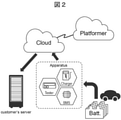
- FIG. 2 is a schematic diagram illustrating the use of the battery management device according to the present invention.
- Batteries that need to be charged and discharged eg, battery cells, battery modules, battery packs, etc.
- a tester e.g., a BMS (battery management system), a charger, and the like.
- the battery is connected to these devices, it is in a charging operation / discharging operation / hibernation state.
- Ri and SOH can be calculated on the above device, for example, or on a computer connected via a network such as on a cloud server. You can also.
- the advantage of calculating on a device to which a battery is connected is that the battery status (voltage output by the battery, current output by the battery, temperature of the battery, etc.) can be obtained frequently.
- Ri and SOH calculated on the cloud system can also be sent to the computer owned by the user.
- the user computer can use this data for a specific purpose such as inventory management.
- Ri and SOH calculated on the cloud system can be stored in the database of the cloud platform operator and used for other purposes. For example, optimization of exchange routes for electric vehicles, energy management, etc.
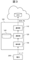
- FIG. 3 is a diagram showing a configuration example of the battery management device 100 according to the first embodiment of the present invention.
- the battery management device 100 is a device that is connected to the battery 200 and receives power from the battery 200, and corresponds to the tester or the like in FIG.
- the battery management device 100 includes a communication unit 110, a calculation unit 120, a detection unit 130, and a storage unit 140.
- the detection unit 130 acquires the detection value V of the voltage output by the battery 200 and the detection value I of the current output by the battery 200. Further, as an option, the detected value T of the temperature of the battery 200 may be acquired. These detected values may be detected by the battery 200 itself and notified to the detection unit 130, or may be detected by the detection unit 130. Details of the detection unit 130 will be described later.
- the calculation unit 120 estimates Ri and SOH of the battery 200 using the detection value acquired by the detection unit 130. The estimation procedure will be described later.
- the communication unit 110 transmits the R and SOH estimated by the calculation unit 120 to the outside of the battery management device 100. For example, these can be transmitted to the memory provided in the cloud system.
- the storage unit 140 stores a data table described later.
- FIG. 4 is a diagram showing another configuration example of the battery management device 100.
- the battery management device 100 does not necessarily have to be a device that is directly connected to the battery 200 to receive electric power, and shows a form in which the communication unit 110 and the detection unit 130 shown in FIG. 3 are not included. ..
- the battery management device 100 acquires the voltage V, the current I, and the temperature T of the battery 200 from the communication unit 110.
- the detection unit 150 included in the battery management device 100 receives these detected values, for example, via a network, and the arithmetic unit 120 calculates Ri and SOH using these detected values.
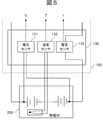
- FIG. 5 shows a configuration example when the detection unit 130 is connected to the battery 200.
- the detection unit 130 may be configured as a part of the battery management device 100, or may be configured as a module separate from the battery management device 100.
- the detection unit 130 includes a voltage sensor 131, a temperature sensor 132, and a current sensor 133 in order to acquire the voltage V, the temperature T, and the current I during the charging / discharging operation of the battery 200.
- the voltage sensor 131 measures the voltage across the battery 200 (the voltage output by the battery 200).
- the temperature sensor 132 is connected to, for example, a thermocouple included in the battery 200, and measures the temperature of the battery 200 through the thermocouple.
- the current sensor 133 is connected to one end of the battery 200 and measures the current output by the battery 200.
- the temperature sensor 132 is an option and does not necessarily have to be provided.
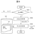
- FIG. 6 is a flowchart illustrating a procedure in which the calculation unit 120 calculates Ri and SOH.
- the calculation unit 120 starts the flowchart at an appropriate timing, for example, when the battery management device 100 is started, when instructed to start the flowchart, or at predetermined intervals. Each step of FIG. 6 will be described below.
- Step S601 The calculation unit 120 determines whether or not it is a pause period after charging or a pause period after discharging. If the current period is not a rest period, this flowchart ends. If it is a rest period, the process proceeds to S602.
- the rest period after discharging means that the current output by the battery 200 changes from a negative value (I ⁇ 0) toward zero, and (b) changes from a negative value to a value near zero and is stable. It can be determined by the fact that (
- Step S602 The calculation unit 120 calculates ⁇ Va and ⁇ Vb.
- ⁇ Va is the fluctuation of the output voltage of the battery 200 from the first calculation time after the end of the rest period to the first time when the first period ta has elapsed.
- ⁇ Vb is the fluctuation of the output voltage of the battery 200 from the second starting time after the first time to the second time when the second period tb has elapsed.
- the calculation unit 120 calculates Ri and SOH according to the following equations 1 and 2.
- fRi defines Ri as a function of ⁇ Va.
- fRi has a parameter (c_Ri_T) that varies depending on the temperature of the battery 200 and a parameter (c_Ri_I) that varies depending on the output current of the battery 200.
- f SOH defines SOH as a function of ⁇ Vb.
- f SOH has a parameter (c_SOH_T) that varies depending on the temperature of the battery 200 and a parameter (c_SOH_I) that varies depending on the output current of the battery 200.
- These parameters are defined by the relation table 141. A specific example of each function and a specific example of the relation table 141 will be described later.
- fRi and fSOH are formulas formed based on, for example, experimental data for each lot.
- Step S604 Calculation formula
- Ri f Ri ( ⁇ Va, c_Ri_T_1, c_Ri_T_2, ..., c_Ri_I_1, c_Ri_I_2, ...)
- SOH f SOH ( ⁇ Vb, c_SOH_T_1, c_SOH_T_2, ..., c_SOH_I_1, c_SOH_I_2, ).
- FIG. 7 is a graph showing changes over time in the current and voltage output by the battery 200 during the rest period after discharge.
- ⁇ Va in S602 is the fluctuation of the output voltage of the battery 200 from the time when the discharge is completed or the time after the first calculation to the first time when the first period ta has elapsed.
- the present inventor has found that the voltage fluctuation due to the internal resistance of the battery 200 is well expressed in the output voltage immediately after the discharge is completed. That is, it can be said that the fluctuation ( ⁇ Va) of the output voltage during this period has a strong correlation with Ri. In the first embodiment, this is used to estimate Ri by ⁇ Va.
- the optimum values for the start time and the time length of ta can be obtained based on the interval from the end of the discharge to the maximum point of the slope change rate in the voltage change curve with time.
- the operation may be appropriately preferable, such as setting the area near or including both ends of the section.
- ⁇ Vb in S602 is the fluctuation of the output voltage of the battery 200 from the time when the period ta has elapsed or after the second calculation time to the second time when the second period tb has elapsed. It can be seen that while ⁇ Va immediately after the end of discharge has a correlation with Ri, the period after that when the output voltage fluctuates gently has a correlation with SOH. , The inventor has found. In the first embodiment, this is used to estimate SOH by ⁇ Vb.
- the optimum values for the start time and time length of tb are based on the interval from the maximum point of the slope change rate in the voltage change curve after the end of discharge until the slope change of the voltage change curve approaches a constant value. Can be obtained. In specifying the section, depending on the type of battery, device, accuracy, etc., the operation may be appropriately preferable, such as setting the area near or including both ends of the section.
- the start time of ta does not necessarily have to be the same as the discharge end time, but it is desirable that it is close to the discharge end time.
- the start time of tb does not necessarily have to be the same as the end time of ta.
- ta and tb have a relationship of ta ⁇ tb.
- ⁇ Va may be larger or ⁇ Vb may be larger.
- Ri and SOH can be estimated accurately even if the total of ta and tb is, for example, about several seconds. Therefore, according to the first embodiment, both Ri and SOH can be quickly estimated during the rest period.
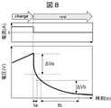
- FIG. 8 is a graph showing changes over time in the current and voltage output by the battery 200 during the rest period after charging.
- ⁇ Va in S602 may be a variation in the output voltage of the battery 200 from the time when charging is completed or after the first calculation time to the first time when the first period ta has elapsed.
- ⁇ Vb in S602 is the fluctuation of the output voltage of the battery 200 from the time when the period ta has elapsed or after the second calculation time to the second time when the second period tb has elapsed.
- the present inventor has found that ⁇ Va has a correlation with Ri and ⁇ Vb has a correlation with SOH even in the rest period after charging. Therefore, in the first embodiment, ⁇ Va and ⁇ Vb in S602 may be acquired after either charging or discharging.
- FIG. 9 is a diagram showing the configuration of the relation table 141 and an example of data.
- the relation table 141 is a data table that defines each parameter in the equations 1 and 2. Since c_Ri_I and c_SOH_I vary depending on the output current of the battery 200, they are defined for each output current value. Since c_Ri_T and c_SOH_T vary depending on the temperature of the battery 200, they are defined for each temperature. Since these parameters may have different characteristics between the rest period after discharge and the rest period after charging, the relation table 141 defines each parameter for each of these periods.
- Ri When f Ri is a linear function of ⁇ Va, Ri can be expressed by, for example, the following equation 3. This is because the slope of Ri is affected by temperature and the intercept is affected by current. In this case, c_Ri_T and c_Ri_I are each one.
- Ri c_Ri_T_1 ⁇ ⁇ Va + c_Ri_I_1 (3)
- SOH When f SOH is a linear function of ⁇ Vb, SOH can be expressed by, for example, the following equation 4. This is because the slope of SOH is affected by temperature and the intercept is affected by current. In this case, c_SOH_T and c_SOH_I are each one.
- the battery management device 100 estimates Ri using the voltage fluctuation ⁇ Va in the period ta in the pause period after the end of discharge or the pause period after the end of charging, and uses the voltage fluctuation ⁇ Vb in the period tb.
- Estimate SOH This makes it possible to estimate both Ri and SOH in a shorter time than before.
- the relationship table 141 describes an internal resistance parameter that defines a function fRi representing the relationship between Ri and ⁇ Va.
- the internal resistance parameter includes c_Ri_I, which varies depending on the output current of the battery 200, and c_Ri_T, which varies depending on the temperature of the battery 200.
- the relation table 141 describes the internal resistance parameter and the deterioration state parameter for each of the rest period after charging and the rest period after discharging. This makes it possible to accurately estimate Ri and SOH even when the function (that is, the characteristics of the battery 200) is different between the rest period after charging and the rest period after discharging.
- FIG. 10 is a diagram showing a configuration example of the relationship table 141 according to the second embodiment of the present invention. It was explained that the relation table 141 in the first embodiment defines the parameters for the rest period after charging and the rest period after discharging. In addition to this, the relation table 141 may define these parameters for each production lot number of the battery 200. This is because the correlation between Ri and ⁇ Va and the correlation between SOH and ⁇ Vb may differ from production lot to production lot. Therefore, in FIG. 10, an example in which one data table is provided for each production lot number is shown. The calculation unit 120 acquires each parameter from the data table corresponding to the production lot number of the battery 200.
- the present invention is not limited to the above-described embodiment, and includes various modifications.
- the above-described embodiment has been described in detail in order to explain the present invention in an easy-to-understand manner, and is not necessarily limited to the one including all the described configurations.
- it is possible to replace a part of the configuration of one embodiment with the configuration of another embodiment and it is also possible to add the configuration of another embodiment to the configuration of one embodiment.
- ⁇ Va and ⁇ Vb are acquired during the rest period after discharge or the rest period after charging.
- the discharge or charge at this time does not necessarily have to be a complete discharge (the remaining capacity of the battery 200 is 0) or a complete charge (the battery 200 is fully charged). That is, it may be a period after the discharge operation or the charge operation is completed.
- the acquisition of ⁇ Va and ⁇ Vb during the pause period after discharge or the pause period after charge means that the output current of the battery 200 rises sharply immediately after the end of discharge, and the battery immediately after the end of charge. It is assumed that the output current of 200 drops sharply. For example, it is assumed that the current rises or falls in a rectangular wave shape. This is because it is considered that the voltage response of the battery 200 to various frequency components of the output current can be obtained because the output current is a rectangular wave. Therefore, it is desirable that the output current of the battery 200 fluctuates in a rectangular wave shape during the rest period after discharging or the rest period after charging. However, it does not have to be a strict rectangular wave, but may be a current waveform that approximates a rectangular wave.
- the linear function is illustrated as an example of the functions fRi and fSOH , but other functions may be used.
- it may be a polynomial function of a quadratic function or more.
- the relation table 141 may describe parameters such as coefficients for defining the function. Among the parameters, those that fluctuate depending on the output current of the battery 200 may be defined for each current value, and those that fluctuate depending on the temperature of the battery 200 may be defined for each temperature value.
- the arithmetic unit 120 and the detection unit 130 can be configured by hardware such as a circuit device that implements these functions, and software that implements these functions is a CPU (Central Processing Unit) or the like. It can also be configured by executing the arithmetic unit of.
- hardware such as a circuit device that implements these functions, and software that implements these functions is a CPU (Central Processing Unit) or the like. It can also be configured by executing the arithmetic unit of.
- CPU Central Processing Unit
- the storage unit 140 does not necessarily have to be arranged on the same device as the calculation unit 120. That is, if the arithmetic unit 120 can acquire the information defined by the relational table 141 and store it in a storage device such as a local memory, the relational table 141 itself is arranged on a device different from the arithmetic unit 120. May be good.
- Battery management device 110 Communication unit 120: Calculation unit 130: Detection unit 140: Storage unit 141: Relationship table 200: Battery
Landscapes
- Engineering & Computer Science (AREA)
- General Physics & Mathematics (AREA)
- Physics & Mathematics (AREA)
- Chemical Kinetics & Catalysis (AREA)
- Manufacturing & Machinery (AREA)
- Chemical & Material Sciences (AREA)
- Electrochemistry (AREA)
- General Chemical & Material Sciences (AREA)
- Microelectronics & Electronic Packaging (AREA)
- Power Engineering (AREA)
- Secondary Cells (AREA)
- Charge And Discharge Circuits For Batteries Or The Like (AREA)
- Tests Of Electric Status Of Batteries (AREA)
- Electric Propulsion And Braking For Vehicles (AREA)
Priority Applications (10)
| Application Number | Priority Date | Filing Date | Title |
|---|---|---|---|
| PT209477058T PT4191732T (pt) | 2020-07-29 | 2020-07-29 | Dispositivo de gestão de bateria, método de gestão de bateria |
| PCT/JP2020/028961 WO2022024235A1 (ja) | 2020-07-29 | 2020-07-29 | 電池管理装置、電池管理方法 |
| CN202080102254.8A CN115917341A (zh) | 2020-07-29 | 2020-07-29 | 电池管理装置、电池管理方法 |
| EP20947705.8A EP4191732B1 (en) | 2020-07-29 | 2020-07-29 | Battery management device, battery management method |
| KR1020227044015A KR20230012022A (ko) | 2020-07-29 | 2020-07-29 | 전지 관리 장치, 전지 관리 방법 |
| US18/010,090 US20230349981A1 (en) | 2020-07-29 | 2020-07-29 | Battery management device, battery management method |
| ES20947705T ES3064884T3 (en) | 2020-07-29 | 2020-07-29 | Battery management device, battery management method |
| JP2022539847A JP7390490B2 (ja) | 2020-07-29 | 2020-07-29 | 電池管理装置、電池管理方法 |
| TW110124617A TWI785665B (zh) | 2020-07-29 | 2021-07-05 | 電池管理裝置、電池管理方法 |
| TW111140342A TWI818777B (zh) | 2020-07-29 | 2021-07-05 | 電池管理裝置、電池管理方法 |
Applications Claiming Priority (1)
| Application Number | Priority Date | Filing Date | Title |
|---|---|---|---|
| PCT/JP2020/028961 WO2022024235A1 (ja) | 2020-07-29 | 2020-07-29 | 電池管理装置、電池管理方法 |
Publications (1)
| Publication Number | Publication Date |
|---|---|
| WO2022024235A1 true WO2022024235A1 (ja) | 2022-02-03 |
Family
ID=80035462
Family Applications (1)
| Application Number | Title | Priority Date | Filing Date |
|---|---|---|---|
| PCT/JP2020/028961 Ceased WO2022024235A1 (ja) | 2020-07-29 | 2020-07-29 | 電池管理装置、電池管理方法 |
Country Status (9)
| Country | Link |
|---|---|
| US (1) | US20230349981A1 (https=) |
| EP (1) | EP4191732B1 (https=) |
| JP (1) | JP7390490B2 (https=) |
| KR (1) | KR20230012022A (https=) |
| CN (1) | CN115917341A (https=) |
| ES (1) | ES3064884T3 (https=) |
| PT (1) | PT4191732T (https=) |
| TW (2) | TWI818777B (https=) |
| WO (1) | WO2022024235A1 (https=) |
Cited By (11)
| Publication number | Priority date | Publication date | Assignee | Title |
|---|---|---|---|---|
| CN114966452A (zh) * | 2022-08-01 | 2022-08-30 | 华为电动技术有限公司 | 一种电池状态确定方法及相关装置 |
| WO2022230335A1 (ja) * | 2021-04-28 | 2022-11-03 | 株式会社日立ハイテク | 電池状態推定装置、電力システム |
| CN115308628A (zh) * | 2022-08-16 | 2022-11-08 | 上海工程技术大学 | 一种电池健康状态监测方法 |
| WO2023157373A1 (ja) * | 2022-02-17 | 2023-08-24 | 株式会社日立ハイテク | 電池管理装置、電池管理プログラム |
| WO2023176028A1 (ja) * | 2022-03-16 | 2023-09-21 | 株式会社日立ハイテク | 電池状態推定装置、電池システム、電池状態推定方法 |
| JP2023166782A (ja) * | 2022-05-10 | 2023-11-22 | 株式会社日立製作所 | 電池管理装置 |
| WO2024042758A1 (ja) * | 2022-08-22 | 2024-02-29 | 株式会社日立ハイテク | 電池管理装置、電池管理方法 |
| WO2024189998A1 (ja) | 2023-03-13 | 2024-09-19 | 株式会社日立ハイテク | 電池劣化度管理システム |
| WO2025084779A1 (ko) * | 2023-10-17 | 2025-04-24 | 주식회사 엘지에너지솔루션 | 배터리 관리 장치 및 그것의 동작 방법 |
| EP4333243A4 (en) * | 2021-04-28 | 2025-05-07 | Hitachi High-Tech Corporation | Battery management device, and electric power system |
| JP2025529060A (ja) * | 2022-08-30 | 2025-09-04 | エルジー エナジー ソリューション リミテッド | 電池状態予測装置およびその動作方法 |
Families Citing this family (5)
| Publication number | Priority date | Publication date | Assignee | Title |
|---|---|---|---|---|
| KR20220117063A (ko) * | 2021-02-16 | 2022-08-23 | 주식회사 엘지에너지솔루션 | 배터리 충방전 장치 및 방법 |
| JP7777052B2 (ja) * | 2022-09-05 | 2025-11-27 | 株式会社日立パワーソリューションズ | 電池管理装置、電池管理方法、電池管理プログラム |
| CN115754778A (zh) * | 2022-11-08 | 2023-03-07 | 国网江苏省电力有限公司南京供电分公司 | 一种级联式储能的soc均衡控制方法及装置 |
| JP7449008B1 (ja) * | 2023-03-08 | 2024-03-13 | 東洋システム株式会社 | 車載二次電池診断装置 |
| CN118980932B (zh) * | 2024-06-05 | 2026-01-06 | 北京理工大学 | 一种适用于多场景的新能源汽车电池系统异常检测方法 |
Citations (8)
| Publication number | Priority date | Publication date | Assignee | Title |
|---|---|---|---|---|
| JPH04215083A (ja) * | 1990-10-22 | 1992-08-05 | Yuasa Corp | 鉛蓄電池の残存寿命判定法 |
| JP2008292272A (ja) * | 2007-05-24 | 2008-12-04 | Kri Inc | 蓄電デバイスの電圧予測方法 |
| JP2009288039A (ja) * | 2008-05-29 | 2009-12-10 | Kri Inc | 入出力特性評価システム及びそれを組み込んだ充放電試験装置 |
| WO2017169088A1 (ja) * | 2016-03-31 | 2017-10-05 | パナソニックIpマネジメント株式会社 | リチウムイオン二次電池の寿命推定装置 |
| US20180321323A1 (en) * | 2016-02-29 | 2018-11-08 | University Of Hawaii | Methods and apparatus for updating a fuel gauge and estimating state of health of an energy storage cell |
| JP2018205309A (ja) * | 2017-06-02 | 2018-12-27 | 株式会社Gsユアサ | 管理装置、蓄電モジュール、管理方法、及びコンピュータプログラム |
| WO2019240225A1 (ja) * | 2018-06-14 | 2019-12-19 | 株式会社Gsユアサ | 推定装置、蓄電装置、推定方法、及びコンピュータプログラム |
| JP2020003218A (ja) * | 2018-06-25 | 2020-01-09 | 日立化成株式会社 | 亜鉛電池の劣化の判定方法 |
Family Cites Families (29)
| Publication number | Priority date | Publication date | Assignee | Title |
|---|---|---|---|---|
| KR20070051916A (ko) * | 2004-08-25 | 2007-05-18 | 닛본 덴끼 가부시끼가이샤 | 내부 임피던스 검출 장치, 내부 임피던스 검출 방법,열화도 검출 장치 및 열화도 검출 방법 |
| EP1933158B1 (en) * | 2005-09-16 | 2018-04-25 | The Furukawa Electric Co., Ltd. | Secondary cell degradation judgment method, secondary cell degradation judgment device, and power supply system |
| JP5393182B2 (ja) | 2009-01-31 | 2014-01-22 | カルソニックカンセイ株式会社 | バッテリの内部抵抗成分推定方法及び充電容量推定方法 |
| JP2011142036A (ja) * | 2010-01-08 | 2011-07-21 | Sanyo Electric Co Ltd | 電池管理方法および電子機器 |
| KR20120134415A (ko) * | 2011-06-02 | 2012-12-12 | 에스케이이노베이션 주식회사 | Ess의 배터리 수명 예측 시스템 및 그 방법 |
| CN102393508A (zh) * | 2011-09-30 | 2012-03-28 | 湖南大学 | 无损诊断电池性能 |
| JP5850492B2 (ja) | 2011-10-13 | 2016-02-03 | 学校法人早稲田大学 | 電池システムおよび電池の評価方法 |
| JP5247874B2 (ja) * | 2011-12-06 | 2013-07-24 | パナソニック株式会社 | 蓄電池移転支援装置および蓄電池移転支援方法 |
| JP2014025738A (ja) * | 2012-07-25 | 2014-02-06 | Sanyo Electric Co Ltd | 残容量推定装置 |
| CN103901344A (zh) * | 2012-12-24 | 2014-07-02 | 财团法人金属工业研究发展中心 | 电池残电量估测系统及其估测方法 |
| KR102177721B1 (ko) * | 2014-03-20 | 2020-11-11 | 현대모비스 주식회사 | 배터리팩 열화 상태 추정 장치 및 방법 |
| FR3020142B1 (fr) * | 2014-04-16 | 2016-05-13 | Renault Sa | Procede d'estimation de l'etat de sante d'une batterie |
| CN105092977B (zh) * | 2015-06-05 | 2019-06-21 | 郑贵林 | 蓄电池内阻测量方法和电路、健康状态检测方法和系统 |
| JP6652743B2 (ja) | 2016-01-19 | 2020-02-26 | 日立化成株式会社 | 電池状態推定方法および装置 |
| US10845417B2 (en) * | 2016-01-29 | 2020-11-24 | Vehicle Energy Japan, Inc. | Battery state estimation device, battery control device, battery system, battery state estimation method |
| CN107102263B (zh) * | 2016-02-22 | 2019-10-18 | 华为技术有限公司 | 检测电池健康状态的方法、装置和电池管理系统 |
| TWI581542B (zh) * | 2016-03-01 | 2017-05-01 | 財團法人工業技術研究院 | 電池管理系統及應用其之電池系統 |
| JP2017175705A (ja) * | 2016-03-22 | 2017-09-28 | Ntn株式会社 | 二次電池の劣化抑制装置および個別劣化抑制装置 |
| JP6588632B2 (ja) * | 2016-05-18 | 2019-10-09 | 日立オートモティブシステムズ株式会社 | 電池制御装置 |
| CN106597295B (zh) * | 2016-11-18 | 2021-01-08 | 四川普力科技有限公司 | 一种锂电池soh的估算方法 |
| CN106501736B (zh) * | 2017-01-04 | 2019-08-09 | 山东谦恒电子科技有限公司 | 电池内阻估算方法及装置 |
| CN106970333A (zh) * | 2017-05-05 | 2017-07-21 | 安徽锐能科技有限公司 | 电池内阻检测的方法及装置 |
| CN109752663A (zh) * | 2017-11-01 | 2019-05-14 | 微宏动力系统(湖州)有限公司 | 一种电池内阻的测量方法 |
| TWI741245B (zh) * | 2017-12-29 | 2021-10-01 | 英屬開曼群島商睿能創意公司 | 管理位於裝置交換站中的儲能裝置的系統和方法 |
| JP7101506B2 (ja) * | 2018-03-26 | 2022-07-15 | 日立Astemo株式会社 | 電池劣化判定装置 |
| CN109085513B (zh) * | 2018-10-12 | 2021-02-19 | 东软睿驰汽车技术(沈阳)有限公司 | 一种电池内阻计算的方法和装置 |
| CN109725266B (zh) * | 2018-12-29 | 2021-05-11 | 蜂巢能源科技有限公司 | 一种电池健康状态soh的计算方法及装置 |
| KR102698484B1 (ko) * | 2020-02-07 | 2024-08-23 | 에스케이온 주식회사 | 배터리 관리 장치 및 배터리 관리 방법 |
| JP7583503B2 (ja) * | 2021-04-28 | 2024-11-14 | 株式会社日立ハイテク | 電池管理装置、電力システム |
-
2020
- 2020-07-29 CN CN202080102254.8A patent/CN115917341A/zh active Pending
- 2020-07-29 EP EP20947705.8A patent/EP4191732B1/en active Active
- 2020-07-29 PT PT209477058T patent/PT4191732T/pt unknown
- 2020-07-29 KR KR1020227044015A patent/KR20230012022A/ko not_active Ceased
- 2020-07-29 WO PCT/JP2020/028961 patent/WO2022024235A1/ja not_active Ceased
- 2020-07-29 JP JP2022539847A patent/JP7390490B2/ja active Active
- 2020-07-29 US US18/010,090 patent/US20230349981A1/en active Pending
- 2020-07-29 ES ES20947705T patent/ES3064884T3/es active Active
-
2021
- 2021-07-05 TW TW111140342A patent/TWI818777B/zh active
- 2021-07-05 TW TW110124617A patent/TWI785665B/zh active
Patent Citations (8)
| Publication number | Priority date | Publication date | Assignee | Title |
|---|---|---|---|---|
| JPH04215083A (ja) * | 1990-10-22 | 1992-08-05 | Yuasa Corp | 鉛蓄電池の残存寿命判定法 |
| JP2008292272A (ja) * | 2007-05-24 | 2008-12-04 | Kri Inc | 蓄電デバイスの電圧予測方法 |
| JP2009288039A (ja) * | 2008-05-29 | 2009-12-10 | Kri Inc | 入出力特性評価システム及びそれを組み込んだ充放電試験装置 |
| US20180321323A1 (en) * | 2016-02-29 | 2018-11-08 | University Of Hawaii | Methods and apparatus for updating a fuel gauge and estimating state of health of an energy storage cell |
| WO2017169088A1 (ja) * | 2016-03-31 | 2017-10-05 | パナソニックIpマネジメント株式会社 | リチウムイオン二次電池の寿命推定装置 |
| JP2018205309A (ja) * | 2017-06-02 | 2018-12-27 | 株式会社Gsユアサ | 管理装置、蓄電モジュール、管理方法、及びコンピュータプログラム |
| WO2019240225A1 (ja) * | 2018-06-14 | 2019-12-19 | 株式会社Gsユアサ | 推定装置、蓄電装置、推定方法、及びコンピュータプログラム |
| JP2020003218A (ja) * | 2018-06-25 | 2020-01-09 | 日立化成株式会社 | 亜鉛電池の劣化の判定方法 |
Non-Patent Citations (1)
| Title |
|---|
| See also references of EP4191732A4 * |
Cited By (23)
| Publication number | Priority date | Publication date | Assignee | Title |
|---|---|---|---|---|
| US12461160B2 (en) | 2021-04-28 | 2025-11-04 | Hitachi High-Tech Corporation | Battery management device, and electric power system |
| WO2022230335A1 (ja) * | 2021-04-28 | 2022-11-03 | 株式会社日立ハイテク | 電池状態推定装置、電力システム |
| EP4333243A4 (en) * | 2021-04-28 | 2025-05-07 | Hitachi High-Tech Corporation | Battery management device, and electric power system |
| JP2022170227A (ja) * | 2021-04-28 | 2022-11-10 | 株式会社日立ハイテク | 電池状態推定装置、電力システム |
| EP4333242A4 (en) * | 2021-04-28 | 2025-05-07 | Hitachi High-Tech Corporation | Battery status estimation device and power supply system |
| US12416681B2 (en) | 2021-04-28 | 2025-09-16 | Hitachi High-Tech Corporation | Battery state estimation device and power system |
| JP7620777B2 (ja) | 2021-04-28 | 2025-01-24 | 株式会社日立ハイテク | 電池状態推定装置、電力システム |
| WO2023157373A1 (ja) * | 2022-02-17 | 2023-08-24 | 株式会社日立ハイテク | 電池管理装置、電池管理プログラム |
| JP7653940B2 (ja) | 2022-02-17 | 2025-03-31 | 株式会社日立製作所 | 電池管理装置、電池管理プログラム |
| JP2023119877A (ja) * | 2022-02-17 | 2023-08-29 | 株式会社日立製作所 | 電池管理装置、電池管理プログラム |
| JP2023136212A (ja) * | 2022-03-16 | 2023-09-29 | 株式会社日立ハイテク | 電池状態推定装置、電池システム、電池状態推定方法 |
| WO2023176028A1 (ja) * | 2022-03-16 | 2023-09-21 | 株式会社日立ハイテク | 電池状態推定装置、電池システム、電池状態推定方法 |
| JP7657172B2 (ja) | 2022-03-16 | 2025-04-04 | 株式会社日立ハイテク | 電池状態推定装置、電池システム、電池状態推定方法 |
| JP2023166782A (ja) * | 2022-05-10 | 2023-11-22 | 株式会社日立製作所 | 電池管理装置 |
| JP7809586B2 (ja) | 2022-05-10 | 2026-02-02 | 株式会社日立製作所 | 電池管理装置 |
| CN114966452A (zh) * | 2022-08-01 | 2022-08-30 | 华为电动技术有限公司 | 一种电池状态确定方法及相关装置 |
| CN115308628A (zh) * | 2022-08-16 | 2022-11-08 | 上海工程技术大学 | 一种电池健康状态监测方法 |
| JP2024029593A (ja) * | 2022-08-22 | 2024-03-06 | 株式会社日立製作所 | 電池管理装置、電池管理方法 |
| JP7767244B2 (ja) | 2022-08-22 | 2025-11-11 | 株式会社日立パワーソリューションズ | 電池管理装置、電池管理方法 |
| WO2024042758A1 (ja) * | 2022-08-22 | 2024-02-29 | 株式会社日立ハイテク | 電池管理装置、電池管理方法 |
| JP2025529060A (ja) * | 2022-08-30 | 2025-09-04 | エルジー エナジー ソリューション リミテッド | 電池状態予測装置およびその動作方法 |
| WO2024189998A1 (ja) | 2023-03-13 | 2024-09-19 | 株式会社日立ハイテク | 電池劣化度管理システム |
| WO2025084779A1 (ko) * | 2023-10-17 | 2025-04-24 | 주식회사 엘지에너지솔루션 | 배터리 관리 장치 및 그것의 동작 방법 |
Also Published As
| Publication number | Publication date |
|---|---|
| EP4191732B1 (en) | 2026-02-18 |
| CN115917341A (zh) | 2023-04-04 |
| ES3064884T3 (en) | 2026-04-29 |
| KR20230012022A (ko) | 2023-01-25 |
| EP4191732A1 (en) | 2023-06-07 |
| US20230349981A1 (en) | 2023-11-02 |
| TWI785665B (zh) | 2022-12-01 |
| JP7390490B2 (ja) | 2023-12-01 |
| TW202309544A (zh) | 2023-03-01 |
| JPWO2022024235A1 (https=) | 2022-02-03 |
| EP4191732A4 (en) | 2024-04-17 |
| PT4191732T (pt) | 2026-03-03 |
| TWI818777B (zh) | 2023-10-11 |
| TW202204926A (zh) | 2022-02-01 |
Similar Documents
| Publication | Publication Date | Title |
|---|---|---|
| JP7390490B2 (ja) | 電池管理装置、電池管理方法 | |
| JP7620777B2 (ja) | 電池状態推定装置、電力システム | |
| CN106461732B (zh) | 用于估计电池的健康状态的方法 | |
| JP5269994B2 (ja) | バッテリーの電圧挙動を用いたバッテリーのsoh推定装置及び方法 | |
| US10845417B2 (en) | Battery state estimation device, battery control device, battery system, battery state estimation method | |
| JPWO2019171688A1 (ja) | 二次電池の残存性能評価方法、二次電池の残存性能評価プログラム、演算装置、及び残存性能評価システム | |
| US20170373354A1 (en) | Method and device for detecting states of battery and battery pack | |
| CN110914696A (zh) | 用于在电池的操作期间估计电池开路池格电压、充电状态以及健康状态的方法和系统 | |
| US20140333265A1 (en) | Degradation state estimating method and degradation state estimating apparatus | |
| US12461160B2 (en) | Battery management device, and electric power system | |
| TW201531725A (zh) | 電池內阻估測方法及裝置 | |
| JP2016540961A (ja) | バッテリセルの容量決定のための方法 | |
| JP7414697B2 (ja) | 電池の劣化判定装置、電池の管理システム、電池搭載機器、電池の劣化判定方法、及び、電池の劣化判定プログラム | |
| CN104335058A (zh) | 充电率推断方法以及充电率推断装置 | |
| WO2023027049A1 (ja) | 補正方法、コンピュータプログラム、補正装置及び蓄電デバイス | |
| KR101595956B1 (ko) | 리튬이차전지의 전지잔량 측정 장치 및 방법 | |
| CN113030751A (zh) | 电池荷电状态soc估计方法、装置、管理系统以及车辆 | |
| JP5851514B2 (ja) | 電池制御装置、二次電池システム | |
| JP2016065844A (ja) | 電池システム用制御装置および電池システムの制御方法 | |
| JP2022069223A (ja) | 蓄電池システム、劣化判定装置および劣化判定方法 | |
| TWI802317B (zh) | 電池管理裝置、電池管理方法 | |
| JP7657172B2 (ja) | 電池状態推定装置、電池システム、電池状態推定方法 | |
| WO2025115355A1 (ja) | 二次電池診断システムおよび二次電池診断方法 | |
| CN120686135A (zh) | 一种荷电状态估计方法、装置、电子设备及介质 |
Legal Events
| Date | Code | Title | Description |
|---|---|---|---|
| 121 | Ep: the epo has been informed by wipo that ep was designated in this application |
Ref document number: 20947705 Country of ref document: EP Kind code of ref document: A1 |
|
| ENP | Entry into the national phase |
Ref document number: 20227044015 Country of ref document: KR Kind code of ref document: A |
|
| ENP | Entry into the national phase |
Ref document number: 2022539847 Country of ref document: JP Kind code of ref document: A |
|
| WWE | Wipo information: entry into national phase |
Ref document number: 202217076126 Country of ref document: IN |
|
| WWE | Wipo information: entry into national phase |
Ref document number: 2020947705 Country of ref document: EP |
|
| ENP | Entry into the national phase |
Ref document number: 2020947705 Country of ref document: EP Effective date: 20230228 |
|
| NENP | Non-entry into the national phase |
Ref country code: DE |
|
| WWG | Wipo information: grant in national office |
Ref document number: 2020947705 Country of ref document: EP |