WO2022019280A1 - 入力装置および入力装置の制御方法 - Google Patents
入力装置および入力装置の制御方法 Download PDFInfo
- Publication number
- WO2022019280A1 WO2022019280A1 PCT/JP2021/027021 JP2021027021W WO2022019280A1 WO 2022019280 A1 WO2022019280 A1 WO 2022019280A1 JP 2021027021 W JP2021027021 W JP 2021027021W WO 2022019280 A1 WO2022019280 A1 WO 2022019280A1
- Authority
- WO
- WIPO (PCT)
- Prior art keywords
- input
- user
- fingertip
- unit
- detection mechanism
- Prior art date
- Legal status (The legal status is an assumption and is not a legal conclusion. Google has not performed a legal analysis and makes no representation as to the accuracy of the status listed.)
- Ceased
Links
Images


Classifications
-
- G—PHYSICS
- G02—OPTICS
- G02B—OPTICAL ELEMENTS, SYSTEMS OR APPARATUS
- G02B30/00—Optical systems or apparatus for producing three-dimensional [3D] effects, e.g. stereoscopic images
- G02B30/50—Optical systems or apparatus for producing three-dimensional [3D] effects, e.g. stereoscopic images the image being built up from image elements distributed over a three-dimensional [3D] volume, e.g. voxels
- G02B30/56—Optical systems or apparatus for producing three-dimensional [3D] effects, e.g. stereoscopic images the image being built up from image elements distributed over a three-dimensional [3D] volume, e.g. voxels by projecting aerial or floating images
-
- G—PHYSICS
- G09—EDUCATION; CRYPTOGRAPHY; DISPLAY; ADVERTISING; SEALS
- G09G—ARRANGEMENTS OR CIRCUITS FOR CONTROL OF INDICATING DEVICES USING STATIC MEANS TO PRESENT VARIABLE INFORMATION
- G09G3/00—Control arrangements or circuits, of interest only in connection with visual indicators other than cathode-ray tubes
- G09G3/001—Control arrangements or circuits, of interest only in connection with visual indicators other than cathode-ray tubes using specific devices not provided for in groups G09G3/02 - G09G3/36, e.g. using an intermediate record carrier such as a film slide; Projection systems; Display of non-alphanumerical information, solely or in combination with alphanumerical information, e.g. digital display on projected diapositive as background
-
- G—PHYSICS
- G02—OPTICS
- G02B—OPTICAL ELEMENTS, SYSTEMS OR APPARATUS
- G02B27/00—Optical systems or apparatus not provided for by any of the groups G02B1/00 - G02B26/00, G02B30/00
- G02B27/18—Optical systems or apparatus not provided for by any of the groups G02B1/00 - G02B26/00, G02B30/00 for optical projection, e.g. combination of mirror and condenser and objective
-
- G—PHYSICS
- G06—COMPUTING OR CALCULATING; COUNTING
- G06F—ELECTRIC DIGITAL DATA PROCESSING
- G06F3/00—Input arrangements for transferring data to be processed into a form capable of being handled by the computer; Output arrangements for transferring data from processing unit to output unit, e.g. interface arrangements
- G06F3/01—Input arrangements or combined input and output arrangements for interaction between user and computer
- G06F3/03—Arrangements for converting the position or the displacement of a member into a coded form
- G06F3/0304—Detection arrangements using opto-electronic means
-
- G—PHYSICS
- G06—COMPUTING OR CALCULATING; COUNTING
- G06F—ELECTRIC DIGITAL DATA PROCESSING
- G06F3/00—Input arrangements for transferring data to be processed into a form capable of being handled by the computer; Output arrangements for transferring data from processing unit to output unit, e.g. interface arrangements
- G06F3/01—Input arrangements or combined input and output arrangements for interaction between user and computer
- G06F3/03—Arrangements for converting the position or the displacement of a member into a coded form
- G06F3/041—Digitisers, e.g. for touch screens or touch pads, characterised by the transducing means
- G06F3/042—Digitisers, e.g. for touch screens or touch pads, characterised by the transducing means by opto-electronic means
-
- G—PHYSICS
- G06—COMPUTING OR CALCULATING; COUNTING
- G06F—ELECTRIC DIGITAL DATA PROCESSING
- G06F3/00—Input arrangements for transferring data to be processed into a form capable of being handled by the computer; Output arrangements for transferring data from processing unit to output unit, e.g. interface arrangements
- G06F3/01—Input arrangements or combined input and output arrangements for interaction between user and computer
- G06F3/048—Interaction techniques based on graphical user interfaces [GUI]
- G06F3/0487—Interaction techniques based on graphical user interfaces [GUI] using specific features provided by the input device, e.g. functions controlled by the rotation of a mouse with dual sensing arrangements, or of the nature of the input device, e.g. tap gestures based on pressure sensed by a digitiser
-
- G—PHYSICS
- G06—COMPUTING OR CALCULATING; COUNTING
- G06F—ELECTRIC DIGITAL DATA PROCESSING
- G06F3/00—Input arrangements for transferring data to be processed into a form capable of being handled by the computer; Output arrangements for transferring data from processing unit to output unit, e.g. interface arrangements
- G06F3/01—Input arrangements or combined input and output arrangements for interaction between user and computer
- G06F3/048—Interaction techniques based on graphical user interfaces [GUI]
- G06F3/0487—Interaction techniques based on graphical user interfaces [GUI] using specific features provided by the input device, e.g. functions controlled by the rotation of a mouse with dual sensing arrangements, or of the nature of the input device, e.g. tap gestures based on pressure sensed by a digitiser
- G06F3/0488—Interaction techniques based on graphical user interfaces [GUI] using specific features provided by the input device, e.g. functions controlled by the rotation of a mouse with dual sensing arrangements, or of the nature of the input device, e.g. tap gestures based on pressure sensed by a digitiser using a touch-screen or digitiser, e.g. input of commands through traced gestures
-
- G—PHYSICS
- G06—COMPUTING OR CALCULATING; COUNTING
- G06F—ELECTRIC DIGITAL DATA PROCESSING
- G06F3/00—Input arrangements for transferring data to be processed into a form capable of being handled by the computer; Output arrangements for transferring data from processing unit to output unit, e.g. interface arrangements
- G06F3/14—Digital output to display device ; Cooperation and interconnection of the display device with other functional units
-
- G—PHYSICS
- G06—COMPUTING OR CALCULATING; COUNTING
- G06K—GRAPHICAL DATA READING; PRESENTATION OF DATA; RECORD CARRIERS; HANDLING RECORD CARRIERS
- G06K7/00—Methods or arrangements for sensing record carriers, e.g. for reading patterns
- G06K7/01—Details
- G06K7/015—Aligning or centering of the sensing device with respect to the record carrier
-
- G—PHYSICS
- G06—COMPUTING OR CALCULATING; COUNTING
- G06K—GRAPHICAL DATA READING; PRESENTATION OF DATA; RECORD CARRIERS; HANDLING RECORD CARRIERS
- G06K7/00—Methods or arrangements for sensing record carriers, e.g. for reading patterns
- G06K7/10—Methods or arrangements for sensing record carriers, e.g. for reading patterns by electromagnetic radiation, e.g. optical sensing; by corpuscular radiation
-
- G—PHYSICS
- G06—COMPUTING OR CALCULATING; COUNTING
- G06V—IMAGE OR VIDEO RECOGNITION OR UNDERSTANDING
- G06V20/00—Scenes; Scene-specific elements
- G06V20/10—Terrestrial scenes
- G06V20/17—Terrestrial scenes taken from planes or by drones
-
- G—PHYSICS
- G06—COMPUTING OR CALCULATING; COUNTING
- G06V—IMAGE OR VIDEO RECOGNITION OR UNDERSTANDING
- G06V2201/00—Indexing scheme relating to image or video recognition or understanding
- G06V2201/07—Target detection
-
- G—PHYSICS
- G09—EDUCATION; CRYPTOGRAPHY; DISPLAY; ADVERTISING; SEALS
- G09G—ARRANGEMENTS OR CIRCUITS FOR CONTROL OF INDICATING DEVICES USING STATIC MEANS TO PRESENT VARIABLE INFORMATION
- G09G2354/00—Aspects of interface with display user
Definitions
- the present invention relates to an input device for inputting characters or symbols using the fingertips of a user.
- the present invention also relates to a control method for such an input device.
- an automated teller machine including an aerial image display device and a personal identification number display input unit
- the aerial image display device includes an aerial imaging mechanism and a display unit.
- the personal identification number display input unit includes a personal identification number display unit and a personal identification number input unit.
- a keypad for inputting a personal identification number is displayed on the display unit.
- the aerial imaging mechanism projects a keypad displayed on the display unit into space to form an image as an aerial image and displays it on the personal identification number display unit.
- the personal identification number input unit is provided with a detection mechanism for detecting an operation performed by a user on an aerial image of a keypad displayed on the personal identification number display unit.
- the detection mechanism is, for example, an infrared sensor, a camera, or the like, and detects the position of the user's fingertip on a plane including an aerial image of the keypad displayed on the personal identification number display unit.
- the user can input the personal identification number by sequentially moving the fingertip to the position of a predetermined key of the aerial image of the keypad displayed on the personal identification number display unit. ing.
- an object of the present invention is that various information can be appropriately input in an input device provided with an aerial imaging mechanism for forming an image as an aerial image by projecting an image displayed on a display unit into space.
- an input device provided with an aerial imaging mechanism for forming an image as an aerial image by projecting an image displayed on a display unit into space. It is to provide the control method of the input device.
- the input device of the present invention is an input device for inputting characters or symbols using a user's fingertip, and has a display mechanism having a display unit for displaying an image and a display unit.
- An aerial imaging mechanism that forms an image as an aerial image by projecting the displayed image into space, and a detection mechanism that detects the position of the user's fingertip in the aerial image display area, which is the area where the aerial image is displayed.
- the aerial image display area is an input unit for inputting characters or symbols
- the control unit is a character or symbol input by the user in the input unit.
- notification control is performed to notify the user that the next character or symbol can be input in the input unit.
- the control method of the input device of the present invention is formed as an aerial image by projecting an image displayed on the display unit into space with a display mechanism having a display unit for displaying an image. It is equipped with an aerial imaging mechanism for making an image and a detection mechanism for detecting the position of the user's fingertip in the aerial image display area where the aerial image is displayed.
- the aerial image display area uses the user's fingertip. It is a control method of an input device that is an input unit for inputting characters or symbols, and recognizes characters or symbols input by the user in the input unit based on the detection result of the detection mechanism, and also by the detection mechanism.
- the next character or symbol can be input. It is characterized by performing notification control for notifying the user of the fact.
- the input device includes a detection mechanism for detecting the position of the user's fingertip in the aerial image display area, which is the area where the aerial image is displayed, and the aerial image display area uses the user's fingertip. It is an input unit for inputting characters or symbols. Further, in the present invention, characters or symbols input by the user in the input unit are recognized based on the detection result of the detection mechanism. Therefore, the input device of the present invention enables the user to recognize arbitrary characters and symbols input by using the fingertip.
- the input unit Notification control is performed to notify the user that the next character or symbol can be input in. That is, in the present invention, when it is estimated that the input of one character or symbol is completed, the notification control for notifying the user that the input of the next character or symbol is possible in the input unit is performed. ing. Therefore, in the present invention, even when a user inputs a plurality of characters or symbols, it is possible to appropriately recognize any character or symbol input by the user one by one. Therefore, in the input device of the present invention, various information can be appropriately input.
- characters and symbols can be input even if the user does not hold the fingertip at a predetermined key position in the aerial image of the keypad. This makes it possible for even visually impaired people to enter various information.
- the "symbol” in the present specification means various codes other than characters, and the “symbol” in the present specification is a signature (signature) that cannot be recognized as a character (or is difficult to recognize as a character). ) Is also included.
- the input device includes, for example, a notification sound generation mechanism for generating a notification sound for notifying that the next character or symbol can be input at the input unit, and the control unit detects by the detection mechanism.
- a notification sound generation mechanism for generating a notification sound for notifying that the next character or symbol can be input at the input unit
- the control unit detects by the detection mechanism.
- a control command is issued to the notification sound generation mechanism as notification control.
- the notification sound generation mechanism transmits and generates a notification sound based on a control command from the control unit. In this case, the user recognizes that the following characters or symbols can be input by the notification sound emitted by the notification sound generation mechanism.
- the control unit after a predetermined time elapses after the fingertip detected by the detection mechanism is no longer detected, or the fingertip stopped at a fixed position is detected by the detection mechanism for a predetermined time.
- a notification control a control command is transmitted to the display mechanism, and the display mechanism notifies that the next character or symbol can be input in the input unit based on the control command from the control unit.
- the text is displayed on the display unit, and the aerial imaging mechanism displays the notification text as an aerial image in the aerial image display area. In this case, the user recognizes that the following characters or symbols can be input by the notification text displayed in the aerial image display area as an aerial image.
- control unit transmits data of characters or symbols recognized by the control unit to the display unit
- display mechanism displays the characters or symbols recognized by the control unit on the display unit
- aerial imaging mechanism It is preferable to display the characters or symbols displayed on the display unit as an aerial image in the aerial image display area.
- the input device includes a frame that surrounds the aerial image display area.
- the control unit detects when the fingertip is not detected by the detection mechanism for a predetermined time after performing the notification control, or when the fingertip stopped at a fixed position after performing the notification control.
- the mechanism detects it for a predetermined time, it is determined that the input to the input unit is completed.
- various information can be appropriately input in the input device provided with the aerial imaging mechanism for forming an image as an aerial image by projecting the image displayed on the display unit into space. become.
- FIG. 1 It is a schematic front view for demonstrating the structure of the input device which concerns on embodiment of this invention. It is a schematic side view for demonstrating the structure of the input device shown in FIG. It is a block diagram for demonstrating the structure of the input device shown in FIG. It is a figure which shows an example of the aerial image displayed in the aerial image display area shown in FIG.
- FIG. 1 is a schematic front view for explaining the configuration of the input device 1 according to the embodiment of the present invention.
- FIG. 2 is a schematic side view for explaining the configuration of the input device 1 shown in FIG.
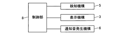
- FIG. 3 is a block diagram for explaining the configuration of the input device 1 shown in FIG.
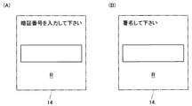
- FIG. 4 is a diagram showing an example of an aerial image displayed in the aerial image display area R shown in FIG.
- the input device 1 of the present embodiment is a device for inputting characters or symbols using the fingertips of the user, and the input device 1 inputs characters or symbols according to the movement of the fingertips of the user.
- the input device 1 is used, for example, in an ATM, a credit card or the like authentication device at the time of payment, an automatic ticket issuing machine, a vending machine, or an entry / exit management device.
- predetermined information composed of characters and symbols is input.
- a personal identification number and a user's signature are input.
- the input device 1 includes a display mechanism 3 having a display unit 2 for displaying an image, an aerial imaging mechanism 4 for forming an aerial image by projecting an image displayed on the display unit 2 into space, and an aerial image.
- a detection mechanism 5 for detecting the position of the user's fingertip in the aerial image display area R, which is a displayed area, a notification sound generation mechanism 6 for generating a notification sound, and a housing 7 accommodating these configurations. It is equipped with.
- the input device 1 includes a control unit 8 for controlling the input device 1.
- the display mechanism 3 is, for example, a liquid crystal display or an organic EL display, and the display unit 2 is a display screen.
- the aerial imaging mechanism 4 includes a beam splitter 11 and a retroreflective material 12.
- the beam splitter 11 is arranged so as to form a predetermined angle with respect to the display unit 2.
- the retroreflective material 12 is arranged so as to form a predetermined angle with respect to the display unit 2 and the beam splitter 11.
- a 1/4 wave plate is attached to one surface of the retroreflective material 12.
- One surface of the retroreflective material 12 to which the 1/4 wave plate is attached is arranged on the beam splitter 11 side.
- the housing 7 includes a frame body 13 that surrounds the hollow image display area R. That is, the input device 1 includes a frame body 13 that surrounds the hollow image display area R.
- the frame 13 is formed in a rectangular or square opening 13a, and the hollow image display region R is formed in the opening 13a.
- the aerial image display area R is an input unit 14 for inputting characters or symbols using the user's fingertips. That is, the detection range of the detection mechanism 5 is the input unit 14.
- the detection mechanism 5 is an optical sensor. Specifically, the detection mechanism 5 is an infrared sensor. Further, the detection mechanism 5 is a line sensor.
- the detection mechanism 5 includes a light emitting unit that emits infrared light and a light receiving unit that receives infrared light emitted from the light emitting unit and reflected by the user's fingertip. That is, the detection mechanism 5 is a reflection type optical sensor.
- the detection mechanism 5 is arranged on the side of the opening 13a. The detection mechanism 5 continuously detects the position of the user's fingertip in the plane including the aerial image display area R (that is, in the plane including the input unit 14).
- the user inputs characters or symbols one by one using a fingertip.
- the characters or symbols input by the input unit 14 are recognized based on the detection result of the detection mechanism 5 (that is, the detection result of the position (movement) of the fingertip of the user).
- the control unit 8 recognizes the characters or symbols input by the user in the input unit 14 based on the detection result of the detection mechanism 5.
- the notification sound generation mechanism 6 is capable of inputting the next character or symbol in the input unit 14 when it is estimated that the input of one character or symbol has been completed in the input unit 14. Generates a notification sound to notify.
- the user In the input device 1, the user, for example, inputs a personal identification number and then a signature.
- a rectangular frame and a guide text indicating the security code input area are displayed as an aerial image in the aerial image display area R.
- the notification sound generation mechanism 6 may notify by voice that the password can be input.
- the control unit 8 recognizes that the input of one character has started when the detection mechanism 5 starts detecting the user's fingertip. Further, the control unit 8 waits for a predetermined time after the user's fingertip detected by the detection mechanism 5 is no longer detected, or the user's fingertip stopped at a fixed position for a predetermined time by the detection mechanism 5. When it is detected (that is, when a predetermined time elapses with the user's fingertip detected by the detection mechanism 5 stopped at a certain position), it is estimated that the input of one character is completed, and the next character is input by the input unit 14. Performs notification control to notify the user that the character of is possible to be input.
- control unit 8 detects the fingertips of the user who have been detected by the detection mechanism 5 and then when a predetermined time elapses or the fingertips of the user who have stopped at a certain position are detected by the detection mechanism 5. When it is detected for a predetermined time, a control command is transmitted to the notification sound generation mechanism 6 as notification control.
- the notification sound generation mechanism 6 generates a notification sound based on a control command from the control unit 8.
- the user recognizes that the next character can be input by the input unit 14 by the notification sound emitted by the notification sound generation mechanism 6.
- the notification sound is, for example, a continuous or intermittent constant sound, or a voice (voice guidance).
- the control unit 8 is input by the user based on the detection result of the detection mechanism 5 from the time when the input of one character is recognized to be started to the time when the input of one character is estimated to be completed. Recognize one character (specifically, a number) entered in.
- the user who hears the notification sound starts inputting the next character in the input unit 14. Similar to the above, the control unit 8 detects the user's fingertips that have been detected by the detection mechanism 5 and then a predetermined time elapses or the user's fingertips that are stopped at a fixed position are detected by the detection mechanism 5. When it is detected for a predetermined time, a control command is transmitted to the notification sound generation mechanism 6, and the notification sound generation mechanism 6 generates a notification sound based on the control command from the control unit 8. The user who hears the notification sound starts inputting the next character in the input unit 14.
- the control unit 8 detects when the user's fingertip is not detected by the detection mechanism 5 for a predetermined time, or after performing notification control, the user's fingertip stopped at a fixed position is detected.
- the mechanism 5 detects it for a predetermined time, it is determined that the input of the personal identification number to the input unit 14 is completed.
- the control unit 8 may determine that the input of the personal identification number is completed based on the number of characters input to the input unit 14. Further, the user may perform a predetermined operation on the input device 1 when the input of the personal identification number is completed.
- the signature entry When the password entry is completed, the signature entry will start.
- the signature input is started, for example, as shown in FIG. 4B, a rectangular frame and a guide text indicating the signature input area are displayed as an aerial image in the aerial image display area R.
- the notification sound generation mechanism 6 may notify by voice that the signature can be input.
- the control unit 8 recognizes that the input of the character or symbol for signature has started when the detection mechanism 5 starts detecting the user's fingertip. Further, the control unit 8 waits for a predetermined time after the user's fingertip detected by the detection mechanism 5 is no longer detected, or the user's fingertip stopped at a fixed position for a predetermined time by the detection mechanism 5. When it is detected, it is estimated that the input of one character or symbol for signature is completed, and notification control is performed to notify the user that the input unit 14 can input the next character or symbol. ..
- the control unit 8 is a user who has stopped at a fixed position after a predetermined time has elapsed after the user's fingertip detected by the detection mechanism 5 is no longer detected.
- a control command is transmitted to the notification sound generation mechanism 6 as notification control, and the notification sound generation mechanism 6 generates a notification sound based on the control command from the control unit 8.
- the user recognizes that the next character or symbol can be input by the input unit 14 by the notification sound emitted by the notification sound generation mechanism 6. Further, the control unit 8 is based on the detection result of the detection mechanism 5 from the time when the input of one character or the symbol is recognized to be started to the time when the input of one character or the symbol is estimated to be completed. Recognizes one character or symbol input by the input unit 14.
- the user who hears the notification sound starts inputting the next character or symbol in the input unit 14. Similar to the above, the control unit 8 detects the user's fingertips that have been detected by the detection mechanism 5 and then a predetermined time elapses or the user's fingertips that are stopped at a fixed position are detected by the detection mechanism 5. When it is detected for a predetermined time, a control command is transmitted to the notification sound generation mechanism 6, and the notification sound generation mechanism 6 generates a notification sound based on the control command from the control unit 8. The user who hears the notification sound starts inputting the next character or symbol in the input unit 14.
- the control unit 8 detects when the user's fingertip is not detected by the detection mechanism 5 for a predetermined time, or after performing notification control, the user's fingertip stopped at a fixed position is detected.
- the mechanism 5 detects it for a predetermined time, it is determined that the signature input to the input unit 14 is completed.
- the user may perform a predetermined operation on the input device 1 when the input of the signature is completed.
- the control unit 8 transmits the character data recognized by the control unit 8 to the display mechanism 3.
- the display mechanism 3 displays the characters recognized by the control unit 8 on the display unit 2. Specifically, each time the control unit 8 recognizes one character, the display mechanism 3 sequentially adds the recognized characters and displays them on the display unit 2.
- the aerial imaging mechanism 4 displays the characters displayed on the display unit 2 as an aerial image in the aerial image display area R.
- the control unit 8 transmits the character or symbol data recognized by the control unit 8 to the display mechanism 3.
- the display mechanism 3 displays the characters or symbols recognized by the control unit 8 on the display unit 2, and the aerial imaging mechanism 4 displays the characters or symbols displayed on the display unit 2 as an aerial image in the aerial image display area R. indicate.
- the input device 1 includes a detection mechanism 5 for detecting the position of the user's fingertip in the aerial image display area R, and the aerial image display area R displays the user's fingertip. It is an input unit 14 for inputting characters or symbols by using it. Further, in the present embodiment, the control unit 8 recognizes the character or symbol input by the user in the input unit 14 based on the detection result of the detection mechanism 5. Therefore, the input device 1 of the present embodiment can recognize arbitrary characters and symbols input by the user using a fingertip.
- the control unit 8 detects the fingertips of the user detected by the detection mechanism 5 after a predetermined time elapses or the fingertips of the user stopped at a fixed position are detected by the detection mechanism. When detected by 5 for a predetermined time, it is estimated that the input of one character or symbol has been completed, and the notification control for notifying the user that the input of the next character or symbol can be input by the input unit 14 is performed. Is going. Specifically, the control unit 8 transmits a control command to the notification sound generation mechanism 6. Further, the notification sound generation mechanism 6 generates a notification sound based on a control command from the control unit 8. Therefore, in the present embodiment, even when a plurality of characters and symbols are input by the user, it is possible to appropriately recognize any characters and symbols input by the user one by one. Therefore, in the input device 1 of this embodiment, various information can be appropriately input.
- control unit 8 transmits the character or symbol data recognized by the control unit 8 to the display mechanism 3. Further, in the present embodiment, the display mechanism 3 displays the characters or symbols recognized by the control unit 8 on the display unit 2, and the aerial imaging mechanism 4 displays the characters or symbols displayed on the display unit 2 as an aerial image. It is displayed in the aerial image display area R. Therefore, in the present embodiment, the user can visually confirm whether or not the character or symbol that the user wants to input matches the character or symbol recognized by the control unit 8.
- a rectangular frame indicating an input area is displayed as an aerial image in the aerial image display area R
- a rectangular frame indicating an input area is displayed. It may be difficult for the visually impaired to enter a PIN or signature inside. In this case, for example, an unevenness corresponding to Braille is formed at a position corresponding to a rectangular frame indicating an input area on the edge of the frame body 13 so that a visually impaired person can recognize the position of the rectangular frame. It should be.
- the control unit 8 may transmit a control command to the display mechanism 3 as notification control.
- the display mechanism 3 displays a notification message on the display unit 2 for notifying that the next character or symbol can be input by the input unit 14 based on the control command from the control unit 8.
- the aerial imaging mechanism 4 displays this notification text as an aerial image in the aerial image display area R.
- the user recognizes that the next character or symbol can be input by the input unit 14 by the notification text displayed in the aerial image display area R as an aerial image.
- the input device 1 may include a vibration mechanism that vibrates the air in the aerial image display region R (that is, the input unit 14).
- the control unit 8 transmits a control command to the vibration mechanism as notification control, and the vibration mechanism receives the air in the aerial image display area R (input unit 14) based on the control command from the control unit 8.
- the vibration mechanism receives the air in the aerial image display area R (input unit 14) based on the control command from the control unit 8.
- the user recognizes that the next character or symbol can be input by the input unit 14 by feeling the vibration of the air in the aerial image display area R with a fingertip.
- the movement pattern of the fingertip and the character or symbol are linked and controlled so that an arbitrary character or symbol is input by moving the fingertip arranged in the input unit 14 in a predetermined pattern. It may be stored in the part 8.
- the input device 1 may include a contact detection mechanism for detecting that the user is touching the edge of the frame body 13.
- characters and symbols to be input are specified based on the detection result of the contact detection mechanism and the operation pattern of the fingertip in the input unit 14 determined in advance. May be. In this case, it becomes easier for the visually impaired to input characters and symbols.
- the detection mechanism 5 is a transmissive optical sensor having a plurality of light emitting units that emit infrared light and a plurality of light receiving units that are incident with infrared light emitted from the light emitting unit. Is also good.
- the detection mechanism 5 has a first detection mechanism having a light emitting portion and a light receiving portion arranged so as to sandwich the aerial image display region R in the left-right direction, and an optical axis of light transmitted through the beam splitter 11.
- the detection mechanism 5 may be a capacitance sensor or a motion sensor. Further, in the above-described embodiment, the detection mechanism 5 may be composed of two cameras. Further, in the above-described embodiment, the characters and symbols recognized by the control unit 8 are displayed in the aerial image display area R as an aerial image, but the characters and symbols recognized by the control unit 8 are displayed in the aerial image display area R. It doesn't have to be.
- the keypad for inputting the personal identification number may be displayed in the aerial image display area R as an aerial image. In this case, the personal identification number is input using the keypad displayed in the aerial image display area R.
- 1 input device 2 display unit, 3 display mechanism, 4 aerial imaging mechanism, 5 detection mechanism, 6 notification sound generation mechanism, 8 control unit, 13 frame body, 14 input unit, R aerial image display area
Landscapes
- Engineering & Computer Science (AREA)
- Physics & Mathematics (AREA)
- Theoretical Computer Science (AREA)
- General Physics & Mathematics (AREA)
- General Engineering & Computer Science (AREA)
- Human Computer Interaction (AREA)
- Optics & Photonics (AREA)
- Artificial Intelligence (AREA)
- Computer Vision & Pattern Recognition (AREA)
- Computer Hardware Design (AREA)
- Remote Sensing (AREA)
- Multimedia (AREA)
- General Health & Medical Sciences (AREA)
- Toxicology (AREA)
- Electromagnetism (AREA)
- Health & Medical Sciences (AREA)
- User Interface Of Digital Computer (AREA)
- Position Input By Displaying (AREA)
- Devices For Indicating Variable Information By Combining Individual Elements (AREA)
- Telephone Set Structure (AREA)
Abstract
表示部に表示される画像を空間に投射することで空中像として結像させる空中結像機構を備える入力装置において、様々な情報を適切に入力することが可能な入力装置を提供する。入力装置1は、空中像が表示される領域である空中像表示領域Rにおいてユーザの指先の位置を検知するための検知機構5を備えており、空中像表示領域Rは、ユーザの指先を用いて文字または記号を入力するための入力部14となっている。入力装置1の制御部は、ユーザによって入力部14で入力された文字または記号を検知機構5の検知結果に基づいて認識するとともに、検知機構5によって検知されていたユーザの指先が検知されなくなった後、所定時間が経過すると、あるいは、一定位置に停止しているユーザの指先が検知機構5によって所定時間検知されると、入力部14での次の文字または記号の入力が可能であることをユーザに通知するための通知制御を行う。
Description
本発明は、ユーザの指先を用いて文字または記号を入力するための入力装置に関する。また、本発明は、かかる入力装置の制御方法に関する。
従来、ATM(Automated Teller Machine)等の自動取引装置として、空中像表示装置と、暗証番号表示入力部とを備える自動取引装置が知られている(たとえば、特許文献1参照)。特許文献1に記載の自動取引装置では、空中像表示装置は、空中結像機構と表示部とを備えている。暗証番号表示入力部は、暗証番号表示部と暗証番号入力部とを備えている。表示部には、暗証番号を入力するためのキーパッドが表示される。空中結像機構は、表示部に表示されるキーパッドを空間に投射することで空中像として結像させて、暗証番号表示部に表示する。
特許文献1の自動取引装置では、暗証番号入力部は、暗証番号表示部に表示されたキーパッドの空中像に対してユーザが行った操作を検知するための検知機構を備えている。検知機構は、たとえば、赤外線センサやカメラ等であり、暗証番号表示部に表示されたキーパッドの空中像を含む平面におけるユーザの指先の位置を検知する。特許文献1の自動取引装置では、暗証番号表示部に表示されたキーパッドの空中像の所定のキーの位置に、ユーザが指先を順次移動させることで、暗証番号を入力することが可能となっている。
特許文献1に記載の自動取引装置では、複数の数字からなる暗証番号を入力することは可能であるが、暗証番号以外の情報を入力することはできない。すなわち、この自動取引装置では、様々な情報を入力することはできない。
そこで、本発明の課題は、表示部に表示される画像を空間に投射することで空中像として結像させる空中結像機構を備える入力装置において、様々な情報を適切に入力することが可能な入力装置を提供することにある。また、本発明の課題は、表示部に表示される画像を空間に投射することで空中像として結像させる空中結像機構を備える入力装置において、様々な情報を適切に入力することが可能となる入力装置の制御方法を提供することにある。
上記の課題を解決するため、本発明の入力装置は、ユーザの指先を用いて文字または記号を入力するための入力装置であって、画像を表示する表示部を有する表示機構と、表示部に表示される画像を空間に投射することで空中像として結像させる空中結像機構と、空中像が表示される領域である空中像表示領域においてユーザの指先の位置を検知するための検知機構と、入力装置を制御するための制御部とを備え、空中像表示領域は、文字または記号を入力するための入力部となっており、制御部は、ユーザによって入力部で入力された文字または記号を検知機構の検知結果に基づいて認識するとともに、検知機構によって検知されていた指先が検知されなくなった後、所定時間が経過すると、あるいは、一定位置に停止している指先が検知機構によって所定時間検知されると、入力部での次の文字または記号の入力が可能であることをユーザに通知するための通知制御を行うことを特徴とする。
また、上記の課題を解決するため、本発明の入力装置の制御方法は、画像を表示する表示部を有する表示機構と、表示部に表示される画像を空間に投射することで空中像として結像させる空中結像機構と、空中像が表示される領域である空中像表示領域においてユーザの指先の位置を検知するための検知機構とを備え、空中像表示領域は、ユーザの指先を用いて文字または記号を入力するための入力部となっている入力装置の制御方法であって、ユーザによって入力部で入力された文字または記号を検知機構の検知結果に基づいて認識するとともに、検知機構によって検知されていた指先が検知されなくなった後、所定時間が経過すると、あるいは、一定位置に停止している指先が検知機構によって所定時間検知されると、次の文字または記号の入力が可能であることをユーザに通知するための通知制御を行うことを特徴とする。
本発明では、入力装置は、空中像が表示される領域である空中像表示領域においてユーザの指先の位置を検知するための検知機構を備えており、空中像表示領域は、ユーザの指先を用いて文字または記号を入力するための入力部となっている。また、本発明では、ユーザによって入力部で入力された文字または記号を検知機構の検知結果に基づいて認識している。そのため、本発明の入力装置では、ユーザが指先を用いて入力する任意の文字および記号を認識することが可能になる。
また、本発明では、検知機構によって検知されていた指先が検知されなくなった後、所定時間が経過すると、あるいは、一定位置に停止している指先が検知機構によって所定時間検知されると、入力部での次の文字または記号の入力が可能であることをユーザに通知するための通知制御を行っている。すなわち、本発明では、1つの文字または記号の入力が終わったことが推定されると、入力部での次の文字または記号の入力が可能であることをユーザに通知するための通知制御を行っている。そのため、本発明では、複数の文字や記号をユーザが入力する場合であっても、ユーザが入力する任意の文字および記号を1つずつ適切に認識することが可能になる。したがって、本発明の入力装置では、様々な情報を適切に入力することが可能になる。
また、本発明では、特許文献1に記載の自動取引装置のように、キーパッドの空中像の所定のキーの位置にユーザが指先を持っていかなくても、文字や記号を入力することが可能になるため、視覚障害者であっても、様々な情報を入力することが可能になる。なお、本明細書における「記号」とは、文字以外の様々な符号を意味しており、本明細書における「記号」には、文字として認識できない(あるいは、文字として認識しにくい)署名(サイン)も含まれている。
本発明において、入力装置は、たとえば、入力部での次の文字または記号の入力が可能であることを知らせるための通知音を発生させる通知音発生機構を備え、制御部は、検知機構によって検知されていた指先が検知されなくなった後、所定時間が経過すると、あるいは、一定位置に停止している指先が検知機構によって所定時間検知されると、通知制御として、通知音発生機構に制御指令を送信し、通知音発生機構は、制御部からの制御指令に基づいて通知音を発生させる。この場合には、通知音発生機構が発する通知音によって、ユーザは、次の文字または記号の入力が可能であることを認識する。
本発明において、たとえば、制御部は、検知機構によって検知されていた指先が検知されなくなった後、所定時間が経過すると、あるいは、一定位置に停止している指先が検知機構によって所定時間検知されると、通知制御として、表示機構に制御指令を送信し、表示機構は、制御部からの制御指令に基づいて、入力部での次の文字または記号の入力が可能であることを知らせるための通知文を表示部に表示し、空中結像機構は、空中像として通知文を空中像表示領域に表示する。この場合には、空中像として空中像表示領域に表示される通知文によって、ユーザは、次の文字または記号の入力が可能であることを認識する。
本発明において、制御部は、制御部が認識した文字または記号のデータを表示機構に送信し、表示機構は、制御部で認識された文字または記号を表示部に表示し、空中結像機構は、表示部に表示された文字または記号を空中像として空中像表示領域に表示することが好ましい。このように構成すると、ユーザが入力したい文字または記号と、制御部で認識される文字または記号とが一致しているのか否かをユーザが目視で確認することが可能になる。
本発明において、入力装置は、空中像表示領域を囲む枠体を備えることが好ましい。このように構成すると、視覚障害者が入力装置を使用する場合であっても、枠体の縁を手掛かりにして空中像表示領域の位置(すなわち、入力部の位置)を適切に把握することが可能になる。したがって、視覚障害者が入力装置を使用する場合であっても、入力部において文字または記号を適切に入力することが可能になる。
本発明において、たとえば、制御部は、通知制御を行った後、検知機構によって指先が検知されない状態が所定時間続くと、あるいは、通知制御を行った後、一定位置に停止している指先が検知機構によって所定時間検知されると、入力部への入力が完了したと判断する。
以上のように、本発明では、表示部に表示される画像を空間に投射することで空中像として結像させる空中結像機構を備える入力装置において、様々な情報を適切に入力することが可能になる。
以下、図面を参照しながら、本発明の実施の形態を説明する。
(入力装置の構成)
図1は、本発明の実施の形態にかかる入力装置1の構成を説明するための概略正面図である。図2は、図1に示す入力装置1の構成を説明するための概略側面図である。図3は、図1に示す入力装置1の構成を説明するためのブロック図である。図4は、図1に示す空中像表示領域Rに表示される空中像の一例を示す図である。
図1は、本発明の実施の形態にかかる入力装置1の構成を説明するための概略正面図である。図2は、図1に示す入力装置1の構成を説明するための概略側面図である。図3は、図1に示す入力装置1の構成を説明するためのブロック図である。図4は、図1に示す空中像表示領域Rに表示される空中像の一例を示す図である。
本形態の入力装置1は、ユーザの指先を用いて文字または記号を入力するための装置であり、入力装置1では、ユーザの指先の動きに応じて文字または記号が入力される。入力装置1は、たとえば、ATM、クレジットカード等の決済時の認証装置、自動発券機、自動販売機、あるいは、入退出管理装置において使用される。本形態の入力装置1では、文字や記号からなる所定の情報が入力される。たとえば、入力装置1では、暗証番号およびユーザの署名(サイン)が入力される。
入力装置1は、画像を表示する表示部2を有する表示機構3と、表示部2に表示される画像を空間に投射することで空中像を結像させる空中結像機構4と、空中像が表示される領域である空中像表示領域Rにおいてユーザの指先の位置を検知するための検知機構5と、通知音を発生させる通知音発生機構6と、これらの構成が収容される筐体7とを備えている。また、入力装置1は、入力装置1を制御するための制御部8を備えている。
表示機構3は、たとえば、液晶ディスプレイまたは有機ELディスプレイであり、表示部2は、ディスプレイの画面である。空中結像機構4は、ビームスプリッタ11と、再帰性反射材12とを備えている。ビームスプリッタ11は、表示部2に対して所定の角度をなすように配置されている。再帰性反射材12は、表示部2およびビームスプリッタ11に対して所定の角度をなすように配置されている。再帰性反射材12の一方の面には、1/4波長板が取り付けられている。1/4波長板が取り付けられた再帰性反射材12の一方の面は、ビームスプリッタ11側に配置されている。
表示部2から射出された光の一部は、ビームスプリッタ11で反射して、再帰性反射材12に入射する。再帰性反射材12に入射した光は、再帰性反射材12への光の入射方向と同じ方向に反射する。再帰性反射材12で反射した光は、ビームスプリッタ11を透過する。ビームスプリッタ11を透過した光によって、空中像表示領域Rに空中像が形成される。筐体7は、中空像表示領域Rを囲む枠体13を備えている。すなわち、入力装置1は、中空像表示領域Rを囲む枠体13を備えている。枠体13には、長方形状または正方形状の開口部13aに形成されており、中空像表示領域Rは開口部13aの中に形成される。
空中像表示領域Rは、ユーザの指先を用いて文字または記号を入力するための入力部14となっている。すなわち、検知機構5の検知範囲は、入力部14となっている。検知機構5は、光学式のセンサである。具体的には、検知機構5は、赤外線センサである。また、検知機構5は、ラインセンサである。検知機構5は、赤外光を射出する発光部と、発光部から射出されてユーザの指先で反射された赤外光が入射する受光部とを備えている。すなわち、検知機構5は、反射型の光学式センサである。検知機構5は、開口部13aの側方に配置されている。検知機構5は、空中像表示領域Rを含む平面内(すなわち、入力部14を含む平面内)においてユーザの指先の位置を連続的に検知する。
入力部14では、ユーザが指先を用いて文字または記号を1つずつ入力する。入力部14で入力された文字または記号は、検知機構5の検知結果(すなわち、ユーザの指先の位置(動き)の検知結果)に基づいて認識される。具体的には、制御部8が、ユーザによって入力部14で入力された文字または記号を検知機構5の検知結果に基づいて認識する。通知音発生機構6は、後述のように、入力部14において1つの文字または記号の入力が終わったことが推定されると、入力部14での次の文字または記号の入力が可能であることを知らせるための通知音を発生させる。
(入力装置の動作)
入力装置1では、ユーザは、たとえば、暗証番号を入力した後、署名を入力する。暗証番号の入力が開始される時には、たとえば、図4(A)に示すように、暗証番号の入力領域を示す長方形の枠および案内文が空中像として、空中像表示領域Rに表示される。ただし、このような空中像が空中像表示領域Rに表示されなくても良い。また、通知音発生機構6が暗証番号の入力が可能であることを音声で通知しても良い。
入力装置1では、ユーザは、たとえば、暗証番号を入力した後、署名を入力する。暗証番号の入力が開始される時には、たとえば、図4(A)に示すように、暗証番号の入力領域を示す長方形の枠および案内文が空中像として、空中像表示領域Rに表示される。ただし、このような空中像が空中像表示領域Rに表示されなくても良い。また、通知音発生機構6が暗証番号の入力が可能であることを音声で通知しても良い。
ユーザは、入力部14において指先を用いて暗証番号の1文字目の入力を開始する。制御部8は、検知機構5によるユーザの指先の検知が開始された時点で、1つの文字の入力が開始されたと認識する。また、制御部8は、検知機構5によって検知されていたユーザの指先が検知されなくなった後、所定時間が経過すると、あるいは、一定位置に停止しているユーザの指先が検知機構5によって所定時間検知されると(すなわち、検知機構5によって検知されるユーザの指先が一定位置に停止した状態で所定時間が経過すると)、1つの文字の入力が終わったと推定して、入力部14での次の文字の入力が可能であることをユーザに通知するための通知制御を行う。
具体的には、制御部8は、検知機構5によって検知されていたユーザの指先が検知されなくなった後、所定時間が経過すると、あるいは、一定位置に停止しているユーザの指先が検知機構5によって所定時間検知されると、通知制御として、通知音発生機構6に制御指令を送信する。通知音発生機構6は、制御部8からの制御指令に基づいて通知音を発生させる。
ユーザは、通知音発生機構6が発する通知音によって、入力部14での次の文字の入力が可能であることを認識する。通知音は、たとえば、連続的または断続的な一定の音、あるいは、音声(音声案内)である。また、制御部8は、1つの文字の入力が開始されたと認識した時点から、1つの文字の入力が終わったと推定される時点までの検知機構5の検知結果に基づいて、ユーザによって入力部14で入力された1つの文字(具体的には、数字)を認識する。
通知音を聞いたユーザは、入力部14において次の文字の入力を開始する。制御部8は、上記と同様に、検知機構5によって検知されていたユーザの指先が検知されなくなった後、所定時間が経過すると、あるいは、一定位置に停止しているユーザの指先が検知機構5によって所定時間検知されると、通知音発生機構6に制御指令を送信し、通知音発生機構6は、制御部8からの制御指令に基づいて通知音を発生させる。通知音を聞いたユーザは、入力部14において次の文字の入力を開始する。
暗証番号の入力が完了すると、通知制御を行って通知音を発生させても、入力部14において次の文字の入力は開始されない。制御部8は、通知制御を行った後、検知機構5によってユーザの指先が検知されない状態が所定時間続くと、あるいは、通知制御を行った後、一定位置に停止しているユーザの指先が検知機構5によって所定時間検知されると、入力部14への暗証番号の入力が完了したと判断する。ただし、制御部8は、入力部14に入力された文字の数によって暗証番号の入力が完了したと判断しても良い。また、暗証番号の入力が完了した時点で、入力装置1に対してユーザが所定の操作を行っても良い。
暗証番号の入力が完了すると、署名の入力が開始される。署名の入力が開始される時には、たとえば、図4(B)に示すように、署名の入力領域を示す長方形の枠および案内文が空中像として、空中像表示領域Rに表示される。ただし、このような空中像が空中像表示領域Rに表示されなくても良い。また、通知音発生機構6が署名の入力が可能であることを音声で通知しても良い。
ユーザは、入力部14において指先を用いて署名の入力を開始する。制御部8は、検知機構5によるユーザの指先の検知が開始された時点で、署名用の文字または記号の入力が開始されたと認識する。また、制御部8は、検知機構5によって検知されていたユーザの指先が検知されなくなった後、所定時間が経過すると、あるいは、一定位置に停止しているユーザの指先が検知機構5によって所定時間検知されると、署名用の1つの文字または記号の入力が終わったと推定して、入力部14での次の文字または記号の入力が可能であることをユーザに通知するための通知制御を行う。
具体的には、上述のように、制御部8は、検知機構5によって検知されていたユーザの指先が検知されなくなった後、所定時間が経過すると、あるいは、一定位置に停止しているユーザの指先が検知機構5によって所定時間検知されると、通知制御として、通知音発生機構6に制御指令を送信し、通知音発生機構6は、制御部8からの制御指令に基づいて通知音を発生させる。
ユーザは、通知音発生機構6が発する通知音によって、入力部14での次の文字または記号の入力が可能であることを認識する。また、制御部8は、1つの文字または記号の入力が開始されたと認識した時点から、1つの文字または記号の入力が終わったと推定される時点までの検知機構5の検知結果に基づいて、ユーザによって入力部14で入力された1つの文字または記号を認識する。
通知音を聞いたユーザは、入力部14において次の文字または記号の入力を開始する。制御部8は、上記と同様に、検知機構5によって検知されていたユーザの指先が検知されなくなった後、所定時間が経過すると、あるいは、一定位置に停止しているユーザの指先が検知機構5によって所定時間検知されると、通知音発生機構6に制御指令を送信し、通知音発生機構6は、制御部8からの制御指令に基づいて通知音を発生させる。通知音を聞いたユーザは、入力部14において次の文字または記号の入力を開始する。
署名の入力が完了すると、通知制御を行って通知音を発生させても、入力部14において次の文字または記号の入力は開始されない。制御部8は、通知制御を行った後、検知機構5によってユーザの指先が検知されない状態が所定時間続くと、あるいは、通知制御を行った後、一定位置に停止しているユーザの指先が検知機構5によって所定時間検知されると、入力部14への署名の入力が完了したと判断する。ただし、署名の入力が完了した時点で、入力装置1に対してユーザが所定の操作を行っても良い。
暗証番号の入力時には、制御部8は、制御部8が認識した文字のデータを表示機構3に送信する。表示機構3は、制御部8で認識された文字を表示部2に表示する。具体的には、表示機構3は、制御部8で1つの文字が認識されるごとに、認識された文字を順次追加して表示部2に表示する。空中結像機構4は、表示部2に表示された文字を空中像として空中像表示領域Rに表示する。同様に、署名の入力時にも、制御部8は、制御部8が認識した文字または記号のデータを表示機構3に送信する。表示機構3は、制御部8で認識された文字または記号を表示部2に表示し、空中結像機構4は、表示部2に表示された文字または記号を空中像として空中像表示領域Rに表示する。
(本形態の主な効果)
以上説明したように、本形態では、入力装置1は、空中像表示領域Rにおいてユーザの指先の位置を検知するための検知機構5を備えており、空中像表示領域Rは、ユーザの指先を用いて文字または記号を入力するための入力部14となっている。また、本形態では、制御部8は、ユーザによって入力部14で入力された文字または記号を検知機構5の検知結果に基づいて認識している。そのため、本形態の入力装置1では、ユーザが指先を用いて入力する任意の文字および記号を認識することが可能になる。
以上説明したように、本形態では、入力装置1は、空中像表示領域Rにおいてユーザの指先の位置を検知するための検知機構5を備えており、空中像表示領域Rは、ユーザの指先を用いて文字または記号を入力するための入力部14となっている。また、本形態では、制御部8は、ユーザによって入力部14で入力された文字または記号を検知機構5の検知結果に基づいて認識している。そのため、本形態の入力装置1では、ユーザが指先を用いて入力する任意の文字および記号を認識することが可能になる。
また、本形態では、制御部8は、検知機構5によって検知されていたユーザの指先が検知されなくなった後、所定時間が経過すると、あるいは、一定位置に停止しているユーザの指先が検知機構5によって所定時間検知されると、1つの文字または記号の入力が終わったと推定して、入力部14での次の文字または記号の入力が可能であることをユーザに通知するための通知制御を行っている。具体的には、制御部8は、通知音発生機構6に制御指令を送信している。また、通知音発生機構6は、制御部8からの制御指令に基づいて通知音を発生させている。そのため、本形態では、複数の文字や記号をユーザが入力する場合であっても、ユーザが入力する任意の文字および記号を1つずつ適切に認識することが可能になる。したがって、本形態の入力装置1では、様々な情報を適切に入力することが可能になる。
本形態では、制御部8は、制御部8が認識した文字または記号のデータを表示機構3に送信している。また、本形態では、表示機構3は、制御部8で認識された文字または記号を表示部2に表示し、空中結像機構4は、表示部2に表示された文字または記号を空中像として空中像表示領域Rに表示している。そのため、本形態では、ユーザが入力したい文字または記号と、制御部8で認識される文字または記号とが一致しているのか否かをユーザが目視で確認することが可能になる。
本形態では、上述した特許文献1に記載の自動取引装置のように、キーパッドの空中像の所定のキーの位置にユーザが指先を持っていかなくても、文字や記号を入力することが可能になる。そのため、本形態の入力装置1では、視覚障害者であっても、様々な情報を入力することが可能になる。特に本形態では、筐体7が、中空像表示領域Rを囲む枠体13を備えているため、視覚障害者が入力装置1を使用する場合であっても、枠体13の縁を手掛かりにして空中像表示領域Rの位置(すなわち、入力部14の位置)を適切に把握することが可能になる。したがって、本形態では、視覚障害者が入力装置1を使用する場合であっても、入力部14において文字または記号を適切に入力することが可能になる。
なお、本形態において、暗証番号の入力領域を示す長方形の枠や署名の入力領域を示す長方形の枠が空中像として空中像表示領域Rに表示される場合には、入力領域を示す長方形の枠の中に視覚障害者が暗証番号や署名を入力することが困難になるおそれがある。この場合には、たとえば、枠体13の縁の、入力領域を示す長方形の枠に対応する位置に、点字に相当する凸凹を形成して、視覚障害者が長方形の枠の位置を認識できるようにすれば良い。
(他の実施の形態)
上述した形態は、本発明の好適な形態の一例ではあるが、これに限定されるものではなく本発明の要旨を変更しない範囲において種々変形実施が可能である。
上述した形態は、本発明の好適な形態の一例ではあるが、これに限定されるものではなく本発明の要旨を変更しない範囲において種々変形実施が可能である。
上述した形態において、制御部8は、通知制御として、表示機構3に制御指令を送信しても良い。この場合には、表示機構3は、制御部8からの制御指令に基づいて、入力部14での次の文字または記号の入力が可能であることを知らせるための通知文を表示部2に表示し、空中結像機構4は、この通知文を空中像として空中像表示領域Rに表示する。この場合には、ユーザは、空中像として空中像表示領域Rに表示される通知文によって、入力部14での次の文字または記号の入力が可能であることを認識する。
上述した形態において、入力装置1は、空中像表示領域R(すなわち、入力部14)の空気を振動させる振動機構を備えていても良い。この場合には、制御部8は、通知制御として、振動機構に制御指令を送信し、振動機構は、制御部8からの制御指令に基づいて、空中像表示領域R(入力部14)の空気を振動させる。ユーザは、空中像表示領域Rの空気の振動を指先で感じることで、入力部14での次の文字または記号の入力が可能であることを認識する。
上述した形態において、入力部14に配置される指先を予め決められたパターンで動かすことで任意の文字や記号が入力されるように、指先の動作パターンと文字や記号とが対応付けられて制御部8に記憶されていても良い。この場合には、入力装置1は、ユーザが枠体13の縁に触れていることを検知するための接触検知機構を備えていても良い。入力装置1が接触検知機構を備えている場合には、接触検知機構の検知結果と、予め決められた入力部14での指先の動作パターンとに基づいて、入力される文字や記号が特定されても良い。この場合には、視覚障害者が文字や記号を入力しやすくなる。
上述した形態において、検知機構5は、赤外光を射出する複数の発光部と、発光部から射出された赤外光が入射する複数の受光部とを有する透過型の光学式センサであっても良い。この場合には、検知機構5は、左右方向において空中像表示領域Rを挟むように配置される発光部と受光部とを有する第1検知機構と、ビームスプリッタ11を透過した光の光軸に直交するとともに左右方向に直交する方向(上下方向、前後方向)において空中像表示領域Rを挟むように配置される発光部と受光部とを有する第2検知機構とから構成されている。また、上述した形態において、検知機構5は、静電容量センサであっても良いし、モーションセンサであっても良い。また、上述した形態において、検知機構5は、2台のカメラによって構成されていても良い。また、上述した形態では、制御部8が認識した文字や記号が空中像として空中像表示領域Rに表示されているが、制御部8が認識した文字や記号が空中像表示領域Rに表示されなくても良い。
上述した形態において、入力装置1に、暗証番号のみが入力されても良いし、署名のみが入力されても良い。また、入力装置1に、暗証番号および署名以外の情報が入力されても良い。また、上述した形態において、暗証番号を入力するためのキーパッドが空中像として空中像表示領域Rに表示されても良い。この場合には、空中像表示領域Rに表示されるキーパッドを利用して暗証番号が入力される。
1 入力装置、 2 表示部、 3 表示機構、 4 空中結像機構、 5 検知機構、 6 通知音発生機構、 8 制御部、 13 枠体、 14 入力部、 R 空中像表示領域
Claims (7)
- ユーザの指先を用いて文字または記号を入力するための入力装置であって、
画像を表示する表示部を有する表示機構と、前記表示部に表示される画像を空間に投射することで空中像として結像させる空中結像機構と、前記空中像が表示される領域である空中像表示領域において前記ユーザの前記指先の位置を検知するための検知機構と、前記入力装置を制御するための制御部とを備え、
前記空中像表示領域は、文字または記号を入力するための入力部となっており、
前記制御部は、前記ユーザによって前記入力部で入力された文字または記号を前記検知機構の検知結果に基づいて認識するとともに、前記検知機構によって検知されていた前記指先が検知されなくなった後、所定時間が経過すると、あるいは、一定位置に停止している前記指先が前記検知機構によって所定時間検知されると、前記入力部での次の文字または記号の入力が可能であることを前記ユーザに通知するための通知制御を行うことを特徴とする入力装置。 - 前記入力部での次の文字または記号の入力が可能であることを知らせるための通知音を発生させる通知音発生機構を備え、
前記制御部は、前記検知機構によって検知されていた前記指先が検知されなくなった後、所定時間が経過すると、あるいは、一定位置に停止している前記指先が前記検知機構によって所定時間検知されると、前記通知制御として、前記通知音発生機構に制御指令を送信し、
前記通知音発生機構は、前記制御部からの制御指令に基づいて前記通知音を発生させることを特徴とする請求項1記載の入力装置。 - 前記制御部は、前記検知機構によって検知されていた前記指先が検知されなくなった後、所定時間が経過すると、あるいは、一定位置に停止している前記指先が前記検知機構によって所定時間検知されると、前記通知制御として、前記表示機構に制御指令を送信し、
前記表示機構は、前記制御部からの制御指令に基づいて、前記入力部での次の文字または記号の入力が可能であることを知らせるための通知文を前記表示部に表示し、
前記空中結像機構は、前記空中像として前記通知文を前記空中像表示領域に表示することを特徴とする請求項1記載の入力装置。 - 前記制御部は、前記制御部が認識した文字または記号のデータを前記表示機構に送信し、
前記表示機構は、前記制御部で認識された文字または記号を前記表示部に表示し、
前記空中結像機構は、前記表示部に表示された文字または記号を前記空中像として前記空中像表示領域に表示することを特徴とする請求項1から3のいずれかに記載の入力装置。 - 前記空中像表示領域を囲む枠体を備えることを特徴とする請求項1から4のいずれかに記載の入力装置。
- 前記制御部は、前記通知制御を行った後、前記検知機構によって前記指先が検知されない状態が所定時間続くと、あるいは、前記通知制御を行った後、一定位置に停止している前記指先が前記検知機構によって所定時間検知されると、前記入力部への入力が完了したと判断することを特徴とする請求項1から5のいずれかに記載の入力装置。
- 画像を表示する表示部を有する表示機構と、前記表示部に表示される画像を空間に投射することで空中像として結像させる空中結像機構と、前記空中像が表示される領域である空中像表示領域においてユーザの指先の位置を検知するための検知機構とを備え、前記空中像表示領域は、前記ユーザの前記指先を用いて文字または記号を入力するための入力部となっている入力装置の制御方法であって、
前記ユーザによって前記入力部で入力された文字または記号を前記検知機構の検知結果に基づいて認識するとともに、前記検知機構によって検知されていた前記指先が検知されなくなった後、所定時間が経過すると、あるいは、一定位置に停止している前記指先が前記検知機構によって所定時間検知されると、次の文字または記号の入力が可能であることを前記ユーザに通知するための通知制御を行うことを特徴とする入力装置の制御方法。
Applications Claiming Priority (4)
| Application Number | Priority Date | Filing Date | Title |
|---|---|---|---|
| US202063054799P | 2020-07-22 | 2020-07-22 | |
| US63/054,799 | 2020-07-22 | ||
| JP2021010026 | 2021-01-26 | ||
| JP2021-010026 | 2021-01-26 |
Publications (1)
| Publication Number | Publication Date |
|---|---|
| WO2022019280A1 true WO2022019280A1 (ja) | 2022-01-27 |
Family
ID=79728608
Family Applications (5)
| Application Number | Title | Priority Date | Filing Date |
|---|---|---|---|
| PCT/JP2021/016980 Ceased WO2022018927A1 (ja) | 2020-07-22 | 2021-04-28 | 空中像表示装置および入力装置 |
| PCT/JP2021/016979 Ceased WO2022018926A1 (ja) | 2020-07-22 | 2021-04-28 | 入力装置および入力装置の制御方法 |
| PCT/JP2021/016982 Ceased WO2022018929A1 (ja) | 2020-07-22 | 2021-04-28 | 非接触式情報処理装置 |
| PCT/JP2021/016981 Ceased WO2022018928A1 (ja) | 2020-07-22 | 2021-04-28 | 空中像表示装置および入力装置 |
| PCT/JP2021/027021 Ceased WO2022019280A1 (ja) | 2020-07-22 | 2021-07-19 | 入力装置および入力装置の制御方法 |
Family Applications Before (4)
| Application Number | Title | Priority Date | Filing Date |
|---|---|---|---|
| PCT/JP2021/016980 Ceased WO2022018927A1 (ja) | 2020-07-22 | 2021-04-28 | 空中像表示装置および入力装置 |
| PCT/JP2021/016979 Ceased WO2022018926A1 (ja) | 2020-07-22 | 2021-04-28 | 入力装置および入力装置の制御方法 |
| PCT/JP2021/016982 Ceased WO2022018929A1 (ja) | 2020-07-22 | 2021-04-28 | 非接触式情報処理装置 |
| PCT/JP2021/016981 Ceased WO2022018928A1 (ja) | 2020-07-22 | 2021-04-28 | 空中像表示装置および入力装置 |
Country Status (3)
| Country | Link |
|---|---|
| US (2) | US20230367136A1 (ja) |
| JP (2) | JPWO2022018928A1 (ja) |
| WO (5) | WO2022018927A1 (ja) |
Families Citing this family (6)
| Publication number | Priority date | Publication date | Assignee | Title |
|---|---|---|---|---|
| WO2023176159A1 (ja) * | 2022-03-18 | 2023-09-21 | マクセル株式会社 | 空間浮遊映像表示装置 |
| JP7828841B2 (ja) * | 2022-07-08 | 2026-03-12 | マクセル株式会社 | 空間浮遊映像表示装置 |
| JP7741018B2 (ja) * | 2022-03-18 | 2025-09-17 | マクセル株式会社 | 空間浮遊映像表示装置 |
| JP7826126B2 (ja) * | 2022-06-16 | 2026-03-09 | マクセル株式会社 | 空間浮遊映像情報表示システム |
| JP7845499B2 (ja) * | 2022-11-18 | 2026-04-14 | Ntt株式会社 | 空中像表示装置および空中像表示方法 |
| DE112023004987T5 (de) * | 2022-11-28 | 2025-10-23 | Subaru Corporation | Informationsübermittlungs-einrichtung |
Citations (4)
| Publication number | Priority date | Publication date | Assignee | Title |
|---|---|---|---|---|
| JP2001075721A (ja) * | 1999-08-31 | 2001-03-23 | Fujitsu Ltd | 図形入力装置及びその方法と図形入力のためのプログラムを記録した記録媒体 |
| JP2010204917A (ja) * | 2009-03-03 | 2010-09-16 | Sharp Corp | 電子機器、情報処理システム、電子機器の制御方法および電子機器の制御プログラム |
| JP2014067071A (ja) * | 2012-09-10 | 2014-04-17 | Askanet:Kk | 空中タッチパネル |
| JP2016009204A (ja) * | 2014-06-20 | 2016-01-18 | 船井電機株式会社 | 画像表示装置 |
Family Cites Families (26)
| Publication number | Priority date | Publication date | Assignee | Title |
|---|---|---|---|---|
| JPH01227495A (ja) * | 1988-03-08 | 1989-09-11 | Canon Inc | 電子機器 |
| JP3015423U (ja) * | 1994-09-19 | 1995-09-05 | 良博 ▲高▼忠 | 液晶モニター用の遮光フードと画面保護カバーの一体化 |
| US8199185B2 (en) * | 1995-09-20 | 2012-06-12 | Videotronic Systems | Reflected camera image eye contact terminal |
| JPH10162177A (ja) * | 1996-10-03 | 1998-06-19 | Omron Corp | 通信装置および該装置を備えた自動改札装置 |
| US6817716B1 (en) * | 1999-10-13 | 2004-11-16 | Stephen P. Hines | Aerial-image display systems |
| JP4167516B2 (ja) * | 2003-03-19 | 2008-10-15 | 株式会社ソフィア | 画像表示装置 |
| JP2005222091A (ja) * | 2004-02-03 | 2005-08-18 | Citizen Watch Co Ltd | 電子機器 |
| JP2010079740A (ja) * | 2008-09-26 | 2010-04-08 | Secom Co Ltd | 監視システム及び監視装置 |
| JP5641906B2 (ja) * | 2010-12-06 | 2014-12-17 | 富士通テン株式会社 | 操作方法及び音響装置 |
| JP5921483B2 (ja) * | 2013-04-05 | 2016-05-24 | 三菱電機株式会社 | 表示装置 |
| JP6411067B2 (ja) * | 2014-05-13 | 2018-10-24 | シャープ株式会社 | 情報処理装置及び入力方法 |
| CN107111149A (zh) * | 2014-12-01 | 2017-08-29 | Sn合伙合同会社 | 空中像显示装置 |
| US20160253651A1 (en) * | 2015-02-27 | 2016-09-01 | Samsung Electronics Co., Ltd. | Electronic device including electronic payment system and operating method thereof |
| JP2017027401A (ja) * | 2015-07-23 | 2017-02-02 | 株式会社デンソー | 表示操作装置 |
| JP6774749B2 (ja) * | 2015-08-19 | 2020-10-28 | 株式会社デンソーウェーブ | カード読取システム |
| WO2017099116A1 (ja) * | 2015-12-07 | 2017-06-15 | 国立大学法人宇都宮大学 | 表示装置及び空中像の表示方法 |
| KR102510944B1 (ko) * | 2016-05-16 | 2023-03-16 | 삼성전자주식회사 | 입체 영상 장치 및 그를 포함하는 전자 장치 |
| JP6604282B2 (ja) * | 2016-07-19 | 2019-11-13 | オムロン株式会社 | 光デバイス及び光システム |
| US10001654B2 (en) * | 2016-07-25 | 2018-06-19 | Disney Enterprises, Inc. | Retroreflector display system for generating floating image effects |
| US9995995B2 (en) * | 2016-11-10 | 2018-06-12 | E-Lead Electronic Co., Ltd. | Head-up display device with dust cover |
| JP2018077438A (ja) * | 2016-11-11 | 2018-05-17 | 株式会社ジャパンディスプレイ | 表示装置 |
| JPWO2019039600A1 (ja) * | 2017-08-25 | 2020-07-30 | 林テレンプ株式会社 | 空中像表示装置 |
| JP7040041B2 (ja) * | 2018-01-23 | 2022-03-23 | 富士フイルムビジネスイノベーション株式会社 | 情報処理装置、情報処理システム及びプログラム |
| JP7017675B2 (ja) * | 2018-02-15 | 2022-02-09 | 有限会社ワタナベエレクトロニクス | 非接触入力システム、方法およびプログラム |
| JP2020039500A (ja) * | 2018-09-07 | 2020-03-19 | ダイコク電機株式会社 | 遊技機用の演出装置及び遊技機 |
| JP7164405B2 (ja) * | 2018-11-07 | 2022-11-01 | 日立チャネルソリューションズ株式会社 | 画像読取り装置及び方法 |
-
2021
- 2021-04-28 WO PCT/JP2021/016980 patent/WO2022018927A1/ja not_active Ceased
- 2021-04-28 US US18/016,791 patent/US20230367136A1/en active Pending
- 2021-04-28 WO PCT/JP2021/016979 patent/WO2022018926A1/ja not_active Ceased
- 2021-04-28 WO PCT/JP2021/016982 patent/WO2022018929A1/ja not_active Ceased
- 2021-04-28 WO PCT/JP2021/016981 patent/WO2022018928A1/ja not_active Ceased
- 2021-04-28 JP JP2022538594A patent/JPWO2022018928A1/ja active Pending
- 2021-04-28 US US18/016,787 patent/US20230290284A1/en not_active Abandoned
- 2021-04-28 JP JP2022538595A patent/JPWO2022018929A1/ja not_active Withdrawn
- 2021-07-19 WO PCT/JP2021/027021 patent/WO2022019280A1/ja not_active Ceased
Patent Citations (4)
| Publication number | Priority date | Publication date | Assignee | Title |
|---|---|---|---|---|
| JP2001075721A (ja) * | 1999-08-31 | 2001-03-23 | Fujitsu Ltd | 図形入力装置及びその方法と図形入力のためのプログラムを記録した記録媒体 |
| JP2010204917A (ja) * | 2009-03-03 | 2010-09-16 | Sharp Corp | 電子機器、情報処理システム、電子機器の制御方法および電子機器の制御プログラム |
| JP2014067071A (ja) * | 2012-09-10 | 2014-04-17 | Askanet:Kk | 空中タッチパネル |
| JP2016009204A (ja) * | 2014-06-20 | 2016-01-18 | 船井電機株式会社 | 画像表示装置 |
Also Published As
| Publication number | Publication date |
|---|---|
| WO2022018928A1 (ja) | 2022-01-27 |
| WO2022018927A1 (ja) | 2022-01-27 |
| US20230367136A1 (en) | 2023-11-16 |
| JPWO2022018928A1 (ja) | 2022-01-27 |
| JPWO2022018929A1 (ja) | 2022-01-27 |
| WO2022018929A1 (ja) | 2022-01-27 |
| US20230290284A1 (en) | 2023-09-14 |
| WO2022018926A1 (ja) | 2022-01-27 |
Similar Documents
| Publication | Publication Date | Title |
|---|---|---|
| JP4039344B2 (ja) | タッチパネルを備えた表示装置 | |
| WO2022018926A1 (ja) | 入力装置および入力装置の制御方法 | |
| JP4568310B2 (ja) | タッチパネルを備えた表示装置 | |
| JP4500485B2 (ja) | タッチパネルを備えた表示装置 | |
| CN103620535B (zh) | 信息输入装置 | |
| JP3953434B2 (ja) | 画像表示装置 | |
| JP6093108B2 (ja) | 遊技機 | |
| US8016198B2 (en) | Alignment and non-alignment assist images | |
| JP2018206149A (ja) | 入力装置 | |
| JP5927867B2 (ja) | 表示システム、及び操作入力方法 | |
| JP7164405B2 (ja) | 画像読取り装置及び方法 | |
| US20140002367A1 (en) | System and device with three-dimensional image display | |
| CN116530099A (zh) | 空间悬浮影像显示装置 | |
| JP2012223465A (ja) | 遊技機 | |
| JP2006209279A (ja) | 入力装置および触読文字記号入力方法 | |
| WO2022018972A1 (ja) | 入力装置および入力装置の制御方法 | |
| JP2002049461A (ja) | データ入力装置 | |
| JP2000181602A (ja) | スイッチ付処理システムおよびスイッチ装置 | |
| JP2014191750A (ja) | 入力装置、入力方法及び電子機器 | |
| WO2018143313A1 (ja) | ウェアラブル電子機器 | |
| JP7064173B2 (ja) | 情報処理装置及びプログラム | |
| JP2018114650A (ja) | 情報処理装置、操作位置表示方法および操作位置表示プログラム | |
| JP2018036913A (ja) | 読取装置 | |
| WO2016067397A1 (ja) | 感覚提示装置、操作処理装置及び画像表示装置 | |
| JP6394800B2 (ja) | 画像形成装置 |
Legal Events
| Date | Code | Title | Description |
|---|---|---|---|
| 121 | Ep: the epo has been informed by wipo that ep was designated in this application |
Ref document number: 21845202 Country of ref document: EP Kind code of ref document: A1 |
|
| NENP | Non-entry into the national phase |
Ref country code: DE |
|
| 122 | Ep: pct application non-entry in european phase |
Ref document number: 21845202 Country of ref document: EP Kind code of ref document: A1 |
|
| NENP | Non-entry into the national phase |
Ref country code: JP |