WO2022018917A1 - アッテネータ装置及びレーザ加工装置 - Google Patents
アッテネータ装置及びレーザ加工装置 Download PDFInfo
- Publication number
- WO2022018917A1 WO2022018917A1 PCT/JP2021/015881 JP2021015881W WO2022018917A1 WO 2022018917 A1 WO2022018917 A1 WO 2022018917A1 JP 2021015881 W JP2021015881 W JP 2021015881W WO 2022018917 A1 WO2022018917 A1 WO 2022018917A1
- Authority
- WO
- WIPO (PCT)
- Prior art keywords
- pair
- window
- optical axis
- windows
- window pair
- Prior art date
- Legal status (The legal status is an assumption and is not a legal conclusion. Google has not performed a legal analysis and makes no representation as to the accuracy of the status listed.)
- Ceased
Links
Images


Classifications
-
- B—PERFORMING OPERATIONS; TRANSPORTING
- B23—MACHINE TOOLS; METAL-WORKING NOT OTHERWISE PROVIDED FOR
- B23K—SOLDERING OR UNSOLDERING; WELDING; CLADDING OR PLATING BY SOLDERING OR WELDING; CUTTING BY APPLYING HEAT LOCALLY, e.g. FLAME CUTTING; WORKING BY LASER BEAM
- B23K26/00—Working by laser beam, e.g. welding, cutting or boring
- B23K26/02—Positioning or observing the workpiece, e.g. with respect to the point of impact; Aligning, aiming or focusing the laser beam
- B23K26/06—Shaping the laser beam, e.g. by masks or multi-focusing
- B23K26/064—Shaping the laser beam, e.g. by masks or multi-focusing by means of optical elements, e.g. lenses, mirrors or prisms
- B23K26/0648—Shaping the laser beam, e.g. by masks or multi-focusing by means of optical elements, e.g. lenses, mirrors or prisms comprising lenses
-
- G—PHYSICS
- G02—OPTICS
- G02B—OPTICAL ELEMENTS, SYSTEMS OR APPARATUS
- G02B26/00—Optical devices or arrangements for the control of light using movable or deformable optical elements
- G02B26/02—Optical devices or arrangements for the control of light using movable or deformable optical elements for controlling the intensity of light
- G02B26/023—Optical devices or arrangements for the control of light using movable or deformable optical elements for controlling the intensity of light comprising movable attenuating elements, e.g. neutral density filters
-
- G—PHYSICS
- G02—OPTICS
- G02B—OPTICAL ELEMENTS, SYSTEMS OR APPARATUS
- G02B27/00—Optical systems or apparatus not provided for by any of the groups G02B1/00 - G02B26/00, G02B30/00
- G02B27/28—Optical systems or apparatus not provided for by any of the groups G02B1/00 - G02B26/00, G02B30/00 for polarising
- G02B27/281—Optical systems or apparatus not provided for by any of the groups G02B1/00 - G02B26/00, G02B30/00 for polarising used for attenuating light intensity, e.g. comprising rotatable polarising elements
-
- G—PHYSICS
- G02—OPTICS
- G02B—OPTICAL ELEMENTS, SYSTEMS OR APPARATUS
- G02B5/00—Optical elements other than lenses
- G02B5/30—Polarising elements
- G02B5/3025—Polarisers, i.e. arrangements capable of producing a definite output polarisation state from an unpolarised input state
- G02B5/3066—Polarisers, i.e. arrangements capable of producing a definite output polarisation state from an unpolarised input state involving the reflection of light at a particular angle of incidence, e.g. Brewster's angle
-
- G—PHYSICS
- G02—OPTICS
- G02B—OPTICAL ELEMENTS, SYSTEMS OR APPARATUS
- G02B5/00—Optical elements other than lenses
- G02B5/30—Polarising elements
- G02B5/3083—Birefringent or phase retarding elements
Definitions
- One aspect of this disclosure relates to an attenuator device and a laser processing device.
- Patent Document 1 As an attenuator that attenuates laser light, for example, there is one described in Patent Document 1.
- the attenuator described in Patent Document 1 includes a pair of windows arranged in a V shape so as to form a brewer angle with the optical axis. On the surface of the window arranged in this way, approximately 100% of the P-polarized light component is transmitted, while only about 50% of the S-polarized light component is transmitted. Therefore, by passing a total of four surfaces of the pair of windows through the laser beam, most of the S-polarized light component can be removed and the laser beam can be attenuated. Further, by rotating the pair of windows around the optical axis, the ratio of the transmitted component can be changed and the attenuation rate of the laser beam can be changed.
- the attenuator as described above to, for example, a laser processing device.
- a laser processing apparatus if the laser light reflected by the object to be machined reverses the transmission path and returns to the laser oscillator, it may cause damage to the oscillator or destabilization of the oscillation output. Therefore, it is required to suppress such return light.
- One aspect of the present disclosure is to provide an attenuator device capable of attenuating laser light and suppressing return light, and a laser processing device including such an attenuator device. ..
- the attenuator device is a pair of first windows having a pair of first windows in which laser light is incident along the optical axis, and each of the pair of first windows is an optical axis and a brewer.
- the pair of first surfaces of one of the pair of first windows contains the pair of first surfaces extending so as to form an angle, and the pair of first surfaces of the other of the pair of first windows with respect to the optical axis.
- a second window having a pair of second windows, a first window pair that is tilted to the opposite side, a rotation holder that holds the first window pair so that the first window pair can rotate about the optical axis, and a pair of second windows.
- a pair of two windows each of which contains a pair of second surfaces extending so as to form an optical axis and a brewer angle, and a pair of second surfaces of one of the pair of second windows. Passed through the second window pair, the first window pair, and the second window pair, which are tilted to the opposite side of the other pair of second surfaces of the pair of second windows with respect to the optical axis. It is arranged so that the laser beam is incident later, and if the wavelength of the laser beam is ⁇ , ⁇ / 4 gives a phase difference of ⁇ / 4 between the polarization component parallel to the optical axis and the polarization component orthogonal to the optical axis.
- the second window pair includes a phase element, and when viewed from a direction parallel to the optical axis, the vibration direction of the P polarization component transmitted through the second window pair is relative to the optical axis of the ⁇ / 4 phase element. It is arranged so as to be tilted by 45 degrees.
- the laser beam passes through a pair of first windows and a pair of second windows.
- Each first window contains a pair of first surfaces extending so as to form a brewer angle with the optical axis
- each second window contains a pair of extending so as to form an optical axis and a brewer angle. Includes a second surface. Therefore, the laser beam passes through a total of eight surfaces extending so as to form a brewer angle with the optical axis. As a result, the laser beam can be attenuated.
- the rotation holding portion rotatably holds the first window pair around the optical axis. As a result, the attenuation rate of the laser beam can be changed by rotating the first window pair.
- the laser beam passing through the first window pair and the second window pair in this order gives a phase difference of ⁇ / 4 between the polarization component parallel to the optical axis and the polarization component orthogonal to the optical axis. It is incident on the phase element.
- the vibration direction of the P-polarized light component transmitted through the second window pair is tilted by 45 degrees with respect to the optical axis of the ⁇ / 4 phase element. Is placed in.
- the second window pair and the ⁇ / 4 phase element can function as an isolator and remove the return light. Therefore, according to this attenuator device, the laser light can be suitably attenuated and the return light can be suppressed.
- the first window pair, the rotation holding unit, and the second window pair may be fixed to each other to form one unit. In this case, the handling of the attenuator device can be facilitated.
- the first window pair and the second window pair may be arranged in one housing. In this case, the handling of the attenuator device can be further facilitated. Further, the laser light reflected by the first window pair and the second window pair can be kept in the housing.
- the housing may be provided with a heat dissipation structure.
- the heat generated by the laser beam reflected by the first window pair and the second window pair can be effectively dissipated.
- the attenuator device may further include a control unit that controls a rotation holding unit so that the rotation angle of the first window pair becomes a rotation angle according to the target strength.
- the attenuation rate of the laser beam can be adjusted to the attenuation rate according to the target intensity.
- the control unit Based on the relationship between the rotation angle of the first window pair and the attenuation rate of the laser beam by the first window pair and the second window pair, the control unit sets the rotation angle of the first window pair as the rotation angle according to the target intensity.
- the rotation holding unit may be controlled so as to be. In this case, the attenuation rate of the laser beam can be surely adjusted to the attenuation rate according to the target intensity.
- the laser processing apparatus includes a light source that outputs laser light and the above-mentioned attenuator apparatus. According to this laser processing apparatus, the laser light can be suitably attenuated and the return light can be suppressed for the above-mentioned reason.
- an attenuator device and a laser processing device that can suitably attenuate the laser beam and suppress the return light.
- FIG. 1 It is a block diagram which shows the laser processing apparatus of embodiment. It is a perspective view which shows the appearance of the attenuator apparatus. It is a perspective view which shows the inside of the attenuator apparatus. It is a perspective view for demonstrating the attenuation of light in a brewer surface.
- (A)-(c) is a figure which shows the change of the ratio of the transmission component when the 1st window pair is rotated. It is a figure for demonstrating a ⁇ / 4 phase element.
- (A) and (b) are diagrams for explaining the isolator function. It is a graph which shows the example of the relationship between the number of pulses input to a rotation holding part, and the transmittance.
- the laser processing apparatus 1 shown in FIG. 1 is a processing engine for irradiating a processing object (work) with laser light L to process the processing object.
- the laser processing device 1 includes a light source 2, mirrors 3 and 4, an attenuator device 5, and a control unit 6.
- the attenuator device 5 includes an attenuator unit 7 and a ⁇ / 4 phase element 8.
- the mirrors 3 and 4, the attenuator unit 7 and the ⁇ / 4 phase element 8 are arranged on, for example, a rectangular plate-shaped stage 9.
- the light source 2 is, for example, a carbon dioxide laser oscillator, and outputs a circularly polarized laser beam L.
- the mirror 3 is, for example, a circularly polarized light mirror that reflects the laser beam L emitted from the light source 2 and changes the polarization state of the laser beam L from circularly polarized light to linearly polarized light.
- the mirror 4 reflects the laser beam L from the mirror 3 toward the attenuator unit 7.
- the attenuator unit 7 attenuates the intensity of the laser beam L.
- the ⁇ / 4 phase element 8 reflects the laser beam L that has passed through the attenuator unit 7.
- the laser beam L reflected by the ⁇ / 4 phase element 8 is incident on the object to be machined.
- the control unit 6 is composed of, for example, a computer including a processor (CPU), a RAM as a recording medium, and a ROM (storage unit). The control unit 6 controls the operation of each unit of the laser processing apparatus 1.
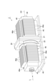
- the attenuator unit 7 includes a first window pair 10, a rotation holding unit 20, a second window pair 30, and a housing 40.
- the first window pair 10 and the second window pair 30 are arranged in a common housing 40.
- the first window pair 10, the rotation holding portion 20, and the second window pair 30 are fixed to the housing 40 and form one unit together with the housing 40.
- the housing 40 has a box-shaped first portion 41 accommodating the first window pair 10 and a box-shaped second portion 42 accommodating the second window pair 30.
- the first portion 41 is formed with an incident portion 43 into which the laser beam L is incident, and the second portion 42 is formed with an exit portion 44 from which the laser beam L is emitted.
- the rotation holding portion 20 is arranged between the first portion 41 and the second portion 42. It can also be considered that a part of the housing 40 is formed by the rotation holding portion 20.
- the first portion 41, the second portion 42, and the rotation holding portion 20 are arranged on the plate member 45.
- a heat dissipation structure 46 is provided on the outer surfaces of the first portion 41 and the second portion 42.
- the heat dissipation structure 46 is composed of a plurality of plate-shaped heat dissipation fins (dampers) 46a arranged along a direction parallel to the optical axis AX, and is composed of an outer surface of the first portion 41 and an outer surface of the second portion 42. It is provided in.
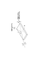
- the first window pair 10 has a pair of first windows 11 facing each other on the optical axis AX.
- the laser beam L that has passed through the incident portion 43 is incident on each first window 11 along the optical axis AX.
- Each first window 11 is formed in a rectangular plate shape by, for example, zinc selenide (ZnSe).
- Each first window 11 contains a pair of first surfaces 11a parallel to each other.
- One pair of first surfaces 11a of the pair of first windows 11 is tilted with respect to the optical axis AX so as to be opposite to the other pair of first surfaces 11a of the pair of first windows 11. That is, the pair of first windows 11 are arranged in a substantially inverted V shape.
- the pair of first windows 11 are arranged plane-symmetrically with respect to a plane orthogonal to the optical axis AX.
- Each first surface 11a extends so as to form a brewer angle with the optical axis AX.
- the brewer angle is an incident angle at which the reflectance of the P-polarized light component becomes 0 at the interface between substances having different refractive indexes.
- P-polarized light is polarized light whose vibration direction is parallel to the surface including the normal of the reflecting surface and the optical axis AX.
- the brewer angle is represented by tan -1 n.
- the surface arranged so that the incident angle is the brewer angle is called the brewer surface. The attenuation of light on the brewer surface will be described later.
- the rotation holding portion 20 has a base 21 and a rotation stage 22.
- the rotary stage 22 is fixed to the base 21 so as to be rotatable around the optical axis AX.
- the pair of first windows 11 are fixed to the rotation stage 22 and can rotate around the optical axis AX. That is, the rotation holding unit 20 holds the first window pair 10 so that the first window pair 10 can rotate around the optical axis AX.
- the positional relationship between the pair of first windows 11 is fixed, and the pair of first windows 11 rotate integrally.
- the operation of the rotation holding unit 20 is controlled by the control unit 6.
- the base 21 and the rotary stage 22 are formed with an opening that penetrates the base 21 and the rotary stage 22 along the optical axis AX, and the laser beam L passes through the opening.
- the second window pair 30 has a pair of second windows 31 facing each other on the optical axis AX.
- a laser beam L transmitted through the first window pair 10 is incident on each second window 31 along the optical axis AX.
- Each second window 31 is formed in a rectangular plate shape, for example, from the same material as the first window 11.
- Each second window 31 contains a pair of second surfaces 31a parallel to each other.
- One pair of second surfaces 31a of the pair of second windows 31 is tilted with respect to the optical axis AX so as to be opposite to the other pair of second surfaces 31a of the pair of second windows 31. That is, the pair of second windows 31 are arranged in a substantially inverted V shape.
- the pair of second windows 31 are arranged plane-symmetrically with respect to a plane orthogonal to the optical axis AX.
- Each second surface 31a extends so as to form a brewer angle with the optical axis AX.
- the positions of the pair of second windows 31 are fixed in the housing 40.
- the attenuation of light on the brewer surface will be described with reference to FIG.
- the incident angle ⁇ is the brewer angle
- approximately 100% of the P-polarized light component of the incident light is transmitted, while only 50.33% of the S-polarized light component is transmitted.
- the rest are reflected. Therefore, by passing the four first surfaces 11a of the first window pair 10 through the laser beam L, the S-polarized light component can be attenuated to about 6.4% while transmitting approximately 100% of the P-polarized light component. can.
- the four second surfaces 31a of the second window pair 30 through the laser beam L, the S-polarized light component is attenuated to about 6.4% while transmitting approximately 100% of the P-polarized light component. Can be done.
- the optical path shifts due to refraction.
- the pair of first windows 11 are arranged so as to be inclined to the opposite sides, so that one of them is the first.
- the deviation of the optical path generated in one window 11 is corrected when passing through the other first window 11.
- the position of the optical axis AX does not shift before and after passing through the pair of first windows 11.
- the position of the optical axis AX does not shift before and after passing through the pair of second windows 31.
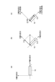
- the first window to 10 is shown simplified as one element.
- FIG. 5A when light having only a P polarization component is incident on the first window pair 10, 100% of the light is transmitted. From this state, when the first window pair 10 is rotated by 45 degrees around the optical axis AX as shown in FIG. 5 (b), the incident light is evenly divided into a P-polarized light component and an S-polarized light component. That is, assuming that the P-polarized light component in FIG. 5 (a) is 1, the P-polarized light component and the S-polarized light component are 0.5 each in FIG. 5 (b).
- the P-polarized light component is transmitted approximately 100%, but the S-polarized light component is attenuated to 6.4%. Therefore, as shown in FIG. 5 (c), the P-polarized light component transmits 0.5 while the S-polarized light component is transmitted. Only 0.032 of the component is transparent.
- the P polarization component decreases and the S polarization component increases.
- the intensity of transmitted light can be changed. That is, by rotating the first window pair 10 around the optical axis AX, for example, from 0 degrees to 90 degrees, the ratio of transmitted components is changed, and the intensity of transmitted light is continuously changed from 100% to 6.4%. Can be made to.
- the ⁇ / 4 phase element 8 is arranged so that the laser beam L is incident after passing through the first window pair 10 and the second window pair 30 in this order. That is, the ⁇ / 4 phase element 8 is arranged on the downstream side of the second window pair 30 in the traveling direction of the laser beam L. Assuming that the wavelength of the laser beam L is ⁇ , the ⁇ / 4 phase element 8 gives a phase difference of ⁇ / 4 between the polarization component parallel to the optical axis and the polarization component orthogonal to the optical axis.
- the ⁇ / 4 phase element 8 is, for example, a circularly polarized mirror, and gives a phase difference of ⁇ / 4 to the laser beam L while reflecting the incident laser beam L.
- the ⁇ / 4 phase element 8 changes the incident light into circularly polarized light when linearly polarized light is incident. More specifically, the ⁇ / 4 phase element 8 is incident with linearly polarized light tilted 45 degrees with respect to the optical axis OA of the ⁇ / 4 phase element 8 when viewed from a direction parallel to the optical axis AX. In some cases, the incident light is changed to circularly polarized light.
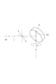
- an isolator that suppresses the return light which is the laser light L reflected by the object to be processed, is configured by the second window pair 30 and the ⁇ / 4 phase element 8.
- the isolator will be described with reference to FIG. 7.
- the second window pair 30 is shown simplified as one element.
- FIG. 7A shows how the laser beam L is irradiated to the workpiece W after passing through the second window pair 30 and the ⁇ / 4 phase element 8 in this order.
- FIG. 7B shows how the return light R reflected by the object W to be processed passes through the ⁇ / 4 phase element 8 and then is reflected and removed by the second window pair 30.
- the ⁇ / 4 phase element 8 is a reflection type element, but FIG. 7 shows an example in which the ⁇ / 4 phase element 8 is a transmission type element. In either case, the operating principle as an isolator is common.
- the laser beam L transmitted through the second window pair 30 is , Can be regarded as a linearly polarized light state having only a P-polarized light component.
- the vibration direction of the P polarization component passing through the second window pair 30 is with respect to the optical axis OA of the ⁇ / 4 phase element 8. It is arranged so as to be tilted at 45 degrees.
- the angle between the normal of each second window 31 (normal of each second surface 31a) and the optical axis OA is 45 degrees. ..
- the laser beam L is converted from linearly polarized light to circularly polarized light by the ⁇ / 4 phase element 8, and the circularly polarized laser beam L is applied to the object W to be processed.
- the processing accuracy can be improved.
- a part of the laser beam L irradiated on the object W to be processed is reflected by the object W to be processed, and becomes a circularly polarized return light R having a phase difference changed by 180 degrees.
- a phase difference of 90 degrees is given to the return light R by the ⁇ / 4 phase element 8.
- the return light R transmitted through the ⁇ / 4 phase element 8 can be regarded as a linearly polarized light state having only the S polarization component.
- the return light R transmitted through the ⁇ / 4 phase element 8 is incident on the second window pair 30. Since the second window pair 30 reflects most of the S polarization component, the return light R is reflected by the second window pair 30 and does not return to the light source 2 side.
- the second window pair 30 and the ⁇ / 4 phase element 8 form an isolator that removes the return light R. Blocking the return light R is particularly important when the reflectance of the workpiece W is high.
- FIG. 8 is a graph showing an example of the relationship between the number of pulses input to the rotation holding unit 20 and the transmittance. As shown in FIG. 8, when a pulse is input to the drive unit that drives the rotation stage 22 of the rotation holding unit 20, the rotation stage 22 rotates, and the first window pair 10 rotates around the optical axis AX, the attenuator device. The transmittance of the laser beam L according to No. 5 changes.
- the state in which the transmittance is maximized is a state in which the rotation angle of the first window to 10 is the same as the rotation angle of the second window to 30, that is, the optical axis AX is that the first window to 10 and the second window to 30 are. Corresponds to the state of being positioned plane-symmetrically with respect to the plane orthogonal to.
- the transmittance becomes the minimum.
- the rotation range of the first window to 10 may be within a range of about 60 degrees. In this case, the transmittance may be minimized when the rotation angle of the first window pair 10 differs from the rotation angle of the second window pair 30 by 60 degrees.
- the laser beam L converted into linearly polarized light by the mirror 3 is incident on the first window pair 10.
- the polarization direction of the linearly polarized laser beam L incident on the first window pair 10 coincides with the normal direction of each second window 31 when viewed from a direction parallel to the optical axis AX. That is, the polarization direction of the linearly polarized laser light L incident on the first window pair 10 is tilted 45 degrees with respect to the optical axis OA of the ⁇ / 4 phase element 8 when viewed from a direction parallel to the optical axis AX. ing.
- the control unit 6 controls the rotation holding unit 20 so that the rotation angle of the first window to 10 becomes a rotation angle according to the target strength.
- the control unit 6 stores the table based on the graph of FIG. 8 in the storage unit.
- the table shows the relationship between the rotation angle of the first window to 10 and the attenuation rate of the laser beam L by the first window to 10 and the second window to 30.
- the control unit 6 controls the rotation holding unit 20 so that the rotation angle of the first window to 10 becomes a rotation angle according to the target strength.
- the laser processing device 1 is arranged between the light source 2 and the attenuator device 5, and further includes a power meter for detecting the intensity of the laser beam L incident on the attenuator device 5.
- the control unit 6 determines the rotation angle of the first window to 10 based on the detected intensity of the laser beam L detected by the power meter, the target intensity, and the above table.
- the target intensity is, for example, the irradiation intensity of the laser beam L on the object W to be processed, and is set by the user.
- the laser beam L passes through the pair of first windows 11 and the pair of second windows 31.
- Each first window 11 includes a pair of first surfaces 11a extending so as to form a brewer angle with the optical axis AX, and each second window 31 so as to form a brewer angle with the optical axis AX. It contains a pair of extending second surfaces 31a. Therefore, the laser beam L passes through a total of eight surfaces extending so as to form a brewer angle with the optical axis AX. As a result, the laser beam L can be attenuated. Further, the rotation holding portion 20 rotatably holds the first window pair 10 around the optical axis AX.
- the attenuation rate of the laser beam L can be changed by rotating the first window pair 10.
- the attenuator device 5 since the laser beam L is attenuated on a total of eight surfaces, a large attenuation range can be secured and the attenuation rate can be greatly changed.
- the laser beam L passing through the first window pair 10 and the second window pair 30 in this order has a phase difference of ⁇ / 4 between the polarization component parallel to the optical axis OA and the polarization component orthogonal to the optical axis OA. It is incident on the ⁇ / 4 phase element 8 that gives.
- the vibration direction of the P polarization component transmitted through the second window pair 30 is with respect to the optical axis OA of the ⁇ / 4 phase element 8. It is arranged so as to be tilted at 45 degrees.
- the second window pair 30 and the ⁇ / 4 phase element 8 function as an isolator, and the return light R can be removed. Therefore, according to the attenuator device 5, the laser beam L can be suitably attenuated and the return light R can be suppressed. Further, it is possible to improve the utilization efficiency of the laser beam L as compared with the case where another polarizing element such as a wave plate is used as a polarizer instead of the second window pair 30 to form an isolator. Further, when the second window pair 30 is omitted and the laser beam L is attenuated only by the first window pair 10, the isolator function cannot be realized depending on the rotation angle of the first window pair 10, but the attenuator device 5 does not.
- the isolator function can be surely realized by providing two window pairs, a first window pair 10 and a second window pair 30. Further, as another dimming means, there is one that uses a wave plate and a polarizing element, but there are problems that the accuracy of the wave plate varies widely and the coating of the wave plate is easily damaged. On the other hand, in the attenuator device 5, such a situation can be avoided.
- the first window pair 10, the rotation holding unit 20 and the second window pair 30 are fixed to each other to form one unit. This makes it possible to facilitate the handling of the attenuator device 5.
- the first window to 10 and the second window to 30 are arranged in a common housing 40. This makes it possible to further facilitate the handling of the attenuator device 5. Further, the laser beam L reflected by the first window pair 10 and the second window pair 30 can be retained in the housing 40.
- the housing 40 is provided with a heat dissipation structure 46. As a result, the heat generated by the laser beam L reflected by the first window pair 10 and the second window pair 30 can be effectively dissipated.
- the control unit 6 Based on the relationship between the rotation angle of the first window to 10 and the attenuation rate of the laser beam L by the first window to 10 and the second window to 30, the control unit 6 sets the rotation angle of the first window to 10 as the target intensity.
- the rotation holding unit 20 is controlled so that the rotation angle corresponds to the above.
- the attenuation rate of the laser beam L can be reliably adjusted to the attenuation rate according to the target intensity.
- the operability and reproducibility can be improved as compared with the case where the user manually adjusts the rotation angle of the first window to 10, for example.
Landscapes
- Physics & Mathematics (AREA)
- Optics & Photonics (AREA)
- General Physics & Mathematics (AREA)
- Engineering & Computer Science (AREA)
- Plasma & Fusion (AREA)
- Mechanical Engineering (AREA)
- Laser Beam Processing (AREA)
- Lasers (AREA)
- Mechanical Light Control Or Optical Switches (AREA)
Priority Applications (4)
| Application Number | Priority Date | Filing Date | Title |
|---|---|---|---|
| KR1020227038238A KR102946766B1 (ko) | 2020-07-21 | 2021-04-19 | 어테뉴에이터 장치 및 레이저 가공 장치 |
| CN202180060829.9A CN116157224A (zh) | 2020-07-21 | 2021-04-19 | 衰减器装置及激光加工装置 |
| EP21845529.3A EP4113190A4 (en) | 2020-07-21 | 2021-04-19 | DAMPING DEVICE AND LASER PROCESSING DEVICE |
| US18/010,272 US20240033849A1 (en) | 2020-07-21 | 2021-04-19 | Attenuator device and laser processing apparatus |
Applications Claiming Priority (2)
| Application Number | Priority Date | Filing Date | Title |
|---|---|---|---|
| JP2020124684A JP7542352B2 (ja) | 2020-07-21 | 2020-07-21 | アッテネータ装置及びレーザ加工装置 |
| JP2020-124684 | 2020-07-21 |
Publications (1)
| Publication Number | Publication Date |
|---|---|
| WO2022018917A1 true WO2022018917A1 (ja) | 2022-01-27 |
Family
ID=79729321
Family Applications (1)
| Application Number | Title | Priority Date | Filing Date |
|---|---|---|---|
| PCT/JP2021/015881 Ceased WO2022018917A1 (ja) | 2020-07-21 | 2021-04-19 | アッテネータ装置及びレーザ加工装置 |
Country Status (7)
| Country | Link |
|---|---|
| US (1) | US20240033849A1 (https=) |
| EP (1) | EP4113190A4 (https=) |
| JP (1) | JP7542352B2 (https=) |
| KR (1) | KR102946766B1 (https=) |
| CN (1) | CN116157224A (https=) |
| TW (1) | TWI888546B (https=) |
| WO (1) | WO2022018917A1 (https=) |
Citations (6)
| Publication number | Priority date | Publication date | Assignee | Title |
|---|---|---|---|---|
| US3655268A (en) | 1970-06-01 | 1972-04-11 | Sylvania Electric Prod | Laser beam attenuator |
| JPS4916000Y1 (https=) * | 1970-03-09 | 1974-04-22 | ||
| JPS59228207A (ja) * | 1983-05-26 | 1984-12-21 | ライノタイプ・ゲゼルシャフト・ミット・ベシュレンクタ−・ハフツング | 可変レ−ザ−ビ−ム減衰器 |
| JPH11258526A (ja) * | 1998-03-16 | 1999-09-24 | Hamamatsu Photonics Kk | 光量調整方法及びその装置 |
| JP2007225905A (ja) * | 2006-02-23 | 2007-09-06 | Asahi Glass Co Ltd | 光アイソレータおよび双方向光送受信装置 |
| CN103984112A (zh) * | 2014-04-23 | 2014-08-13 | 深圳市大族激光科技股份有限公司 | 反射式光学隔离器及采用该反射式光学隔离器的激光加工设备 |
Family Cites Families (4)
| Publication number | Priority date | Publication date | Assignee | Title |
|---|---|---|---|---|
| ATE134927T1 (de) * | 1992-09-28 | 1996-03-15 | Schablonentechnik Kufstein Ag | Verfahren und vorrichtung zum gravieren von rundschablonen |
| AUPS023002A0 (en) | 2002-01-31 | 2002-02-21 | Q-Vis Limited | Variable attenuator |
| JP3655268B2 (ja) | 2002-08-26 | 2005-06-02 | 株式会社東芝 | 燃料電池発電プラント |
| CN203705729U (zh) * | 2014-01-28 | 2014-07-09 | 上海海固电器设备有限公司 | 激光偏振衰减器 |
-
2020
- 2020-07-21 JP JP2020124684A patent/JP7542352B2/ja active Active
-
2021
- 2021-04-19 KR KR1020227038238A patent/KR102946766B1/ko active Active
- 2021-04-19 CN CN202180060829.9A patent/CN116157224A/zh active Pending
- 2021-04-19 WO PCT/JP2021/015881 patent/WO2022018917A1/ja not_active Ceased
- 2021-04-19 US US18/010,272 patent/US20240033849A1/en active Pending
- 2021-04-19 EP EP21845529.3A patent/EP4113190A4/en active Pending
- 2021-04-30 TW TW110115747A patent/TWI888546B/zh active
Patent Citations (6)
| Publication number | Priority date | Publication date | Assignee | Title |
|---|---|---|---|---|
| JPS4916000Y1 (https=) * | 1970-03-09 | 1974-04-22 | ||
| US3655268A (en) | 1970-06-01 | 1972-04-11 | Sylvania Electric Prod | Laser beam attenuator |
| JPS59228207A (ja) * | 1983-05-26 | 1984-12-21 | ライノタイプ・ゲゼルシャフト・ミット・ベシュレンクタ−・ハフツング | 可変レ−ザ−ビ−ム減衰器 |
| JPH11258526A (ja) * | 1998-03-16 | 1999-09-24 | Hamamatsu Photonics Kk | 光量調整方法及びその装置 |
| JP2007225905A (ja) * | 2006-02-23 | 2007-09-06 | Asahi Glass Co Ltd | 光アイソレータおよび双方向光送受信装置 |
| CN103984112A (zh) * | 2014-04-23 | 2014-08-13 | 深圳市大族激光科技股份有限公司 | 反射式光学隔离器及采用该反射式光学隔离器的激光加工设备 |
Non-Patent Citations (1)
| Title |
|---|
| See also references of EP4113190A4 |
Also Published As
| Publication number | Publication date |
|---|---|
| TW202205766A (zh) | 2022-02-01 |
| TWI888546B (zh) | 2025-07-01 |
| KR20230039597A (ko) | 2023-03-21 |
| CN116157224A (zh) | 2023-05-23 |
| JP7542352B2 (ja) | 2024-08-30 |
| EP4113190A1 (en) | 2023-01-04 |
| JP2022021215A (ja) | 2022-02-02 |
| US20240033849A1 (en) | 2024-02-01 |
| EP4113190A4 (en) | 2024-04-10 |
| KR102946766B1 (ko) | 2026-04-02 |
Similar Documents
| Publication | Publication Date | Title |
|---|---|---|
| US4778263A (en) | Variable laser attenuator | |
| US7327518B2 (en) | Attenuator for high-power unpolarized laser beams | |
| TWI457601B (zh) | 偏光方位角調整裝置及雷射加工裝置 | |
| US6061138A (en) | Optical exposure systems and processes for alignment of liquid crystals | |
| JP3107734B2 (ja) | 光学的分離の方法および装置 | |
| KR102454294B1 (ko) | 일산화탄소 레이저 기계 가공 시스템 | |
| US20200154554A1 (en) | Polarizer | |
| US8553311B2 (en) | Method for accomplishing high-speed intensity variation of a polarized output laser beam | |
| WO2022018917A1 (ja) | アッテネータ装置及びレーザ加工装置 | |
| CN213023791U (zh) | 一种激光功率衰减器 | |
| JPS6232674A (ja) | レ−ザ光減衰装置 | |
| JPH02234114A (ja) | レーザビーム減衰器 | |
| JP4465267B2 (ja) | 偏光光照明デバイス | |
| CN115702376A (zh) | 激光强度调整方法及激光强度调整装置 | |
| JP2003066375A (ja) | レーザビーム分岐装置及び分岐方法 | |
| CN112099243A (zh) | 一种激光功率衰减器 | |
| TWI893654B (zh) | 雷射加工裝置 | |
| JP2001009397A (ja) | レーザ照射装置 | |
| JPS6147402B2 (https=) | ||
| JP2026007365A (ja) | テラヘルツ波生成装置 | |
| JP2022021215A5 (https=) | ||
| JPH0818153B2 (ja) | レ−ザ装置 | |
| JPH02173611A (ja) | カライドスコープ | |
| JPH0557561B2 (https=) | ||
| JPH0284613A (ja) | 光アッテネータ |
Legal Events
| Date | Code | Title | Description |
|---|---|---|---|
| 121 | Ep: the epo has been informed by wipo that ep was designated in this application |
Ref document number: 21845529 Country of ref document: EP Kind code of ref document: A1 |
|
| ENP | Entry into the national phase |
Ref document number: 2021845529 Country of ref document: EP Effective date: 20220928 |
|
| WWE | Wipo information: entry into national phase |
Ref document number: 18010272 Country of ref document: US |
|
| NENP | Non-entry into the national phase |
Ref country code: DE |