WO2022018917A1 - Attenuator device and laser processing apparatus - Google Patents
Attenuator device and laser processing apparatus Download PDFInfo
- Publication number
- WO2022018917A1 WO2022018917A1 PCT/JP2021/015881 JP2021015881W WO2022018917A1 WO 2022018917 A1 WO2022018917 A1 WO 2022018917A1 JP 2021015881 W JP2021015881 W JP 2021015881W WO 2022018917 A1 WO2022018917 A1 WO 2022018917A1
- Authority
- WO
- WIPO (PCT)
- Prior art keywords
- pair
- window
- optical axis
- windows
- window pair
- Prior art date
Links
- 230000003287 optical effect Effects 0.000 claims abstract description 79
- 230000010287 polarization Effects 0.000 claims abstract description 28
- 230000017525 heat dissipation Effects 0.000 claims description 7
- 230000002238 attenuated effect Effects 0.000 description 13
- 238000002834 transmittance Methods 0.000 description 7
- 239000000463 material Substances 0.000 description 4
- 230000005540 biological transmission Effects 0.000 description 3
- PFNQVRZLDWYSCW-UHFFFAOYSA-N (fluoren-9-ylideneamino) n-naphthalen-1-ylcarbamate Chemical compound C12=CC=CC=C2C2=CC=CC=C2C1=NOC(=O)NC1=CC=CC2=CC=CC=C12 PFNQVRZLDWYSCW-UHFFFAOYSA-N 0.000 description 2
- CURLTUGMZLYLDI-UHFFFAOYSA-N Carbon dioxide Chemical compound O=C=O CURLTUGMZLYLDI-UHFFFAOYSA-N 0.000 description 2
- 238000010586 diagram Methods 0.000 description 2
- 230000001678 irradiating effect Effects 0.000 description 2
- 239000000126 substance Substances 0.000 description 2
- 230000000903 blocking effect Effects 0.000 description 1
- 229910002092 carbon dioxide Inorganic materials 0.000 description 1
- 239000001569 carbon dioxide Substances 0.000 description 1
- 239000011248 coating agent Substances 0.000 description 1
- 238000000576 coating method Methods 0.000 description 1
- 230000007423 decrease Effects 0.000 description 1
- 230000001687 destabilization Effects 0.000 description 1
- 230000000694 effects Effects 0.000 description 1
- 238000000034 method Methods 0.000 description 1
- 230000010355 oscillation Effects 0.000 description 1
- 230000000717 retained effect Effects 0.000 description 1
Images


Classifications
-
- B—PERFORMING OPERATIONS; TRANSPORTING
- B23—MACHINE TOOLS; METAL-WORKING NOT OTHERWISE PROVIDED FOR
- B23K—SOLDERING OR UNSOLDERING; WELDING; CLADDING OR PLATING BY SOLDERING OR WELDING; CUTTING BY APPLYING HEAT LOCALLY, e.g. FLAME CUTTING; WORKING BY LASER BEAM
- B23K26/00—Working by laser beam, e.g. welding, cutting or boring
- B23K26/02—Positioning or observing the workpiece, e.g. with respect to the point of impact; Aligning, aiming or focusing the laser beam
- B23K26/06—Shaping the laser beam, e.g. by masks or multi-focusing
- B23K26/064—Shaping the laser beam, e.g. by masks or multi-focusing by means of optical elements, e.g. lenses, mirrors or prisms
- B23K26/0648—Shaping the laser beam, e.g. by masks or multi-focusing by means of optical elements, e.g. lenses, mirrors or prisms comprising lenses
-
- G—PHYSICS
- G02—OPTICS
- G02B—OPTICAL ELEMENTS, SYSTEMS OR APPARATUS
- G02B26/00—Optical devices or arrangements for the control of light using movable or deformable optical elements
- G02B26/02—Optical devices or arrangements for the control of light using movable or deformable optical elements for controlling the intensity of light
- G02B26/023—Optical devices or arrangements for the control of light using movable or deformable optical elements for controlling the intensity of light comprising movable attenuating elements, e.g. neutral density filters
-
- G—PHYSICS
- G02—OPTICS
- G02B—OPTICAL ELEMENTS, SYSTEMS OR APPARATUS
- G02B27/00—Optical systems or apparatus not provided for by any of the groups G02B1/00 - G02B26/00, G02B30/00
- G02B27/28—Optical systems or apparatus not provided for by any of the groups G02B1/00 - G02B26/00, G02B30/00 for polarising
- G02B27/281—Optical systems or apparatus not provided for by any of the groups G02B1/00 - G02B26/00, G02B30/00 for polarising used for attenuating light intensity, e.g. comprising rotatable polarising elements
-
- G—PHYSICS
- G02—OPTICS
- G02B—OPTICAL ELEMENTS, SYSTEMS OR APPARATUS
- G02B5/00—Optical elements other than lenses
- G02B5/30—Polarising elements
- G02B5/3025—Polarisers, i.e. arrangements capable of producing a definite output polarisation state from an unpolarised input state
- G02B5/3066—Polarisers, i.e. arrangements capable of producing a definite output polarisation state from an unpolarised input state involving the reflection of light at a particular angle of incidence, e.g. Brewster's angle
-
- G—PHYSICS
- G02—OPTICS
- G02B—OPTICAL ELEMENTS, SYSTEMS OR APPARATUS
- G02B5/00—Optical elements other than lenses
- G02B5/30—Polarising elements
- G02B5/3083—Birefringent or phase retarding elements
Definitions
- One aspect of this disclosure relates to an attenuator device and a laser processing device.
- Patent Document 1 As an attenuator that attenuates laser light, for example, there is one described in Patent Document 1.
- the attenuator described in Patent Document 1 includes a pair of windows arranged in a V shape so as to form a brewer angle with the optical axis. On the surface of the window arranged in this way, approximately 100% of the P-polarized light component is transmitted, while only about 50% of the S-polarized light component is transmitted. Therefore, by passing a total of four surfaces of the pair of windows through the laser beam, most of the S-polarized light component can be removed and the laser beam can be attenuated. Further, by rotating the pair of windows around the optical axis, the ratio of the transmitted component can be changed and the attenuation rate of the laser beam can be changed.
- the attenuator as described above to, for example, a laser processing device.
- a laser processing apparatus if the laser light reflected by the object to be machined reverses the transmission path and returns to the laser oscillator, it may cause damage to the oscillator or destabilization of the oscillation output. Therefore, it is required to suppress such return light.
- One aspect of the present disclosure is to provide an attenuator device capable of attenuating laser light and suppressing return light, and a laser processing device including such an attenuator device. ..
- the attenuator device is a pair of first windows having a pair of first windows in which laser light is incident along the optical axis, and each of the pair of first windows is an optical axis and a brewer.
- the pair of first surfaces of one of the pair of first windows contains the pair of first surfaces extending so as to form an angle, and the pair of first surfaces of the other of the pair of first windows with respect to the optical axis.
- a second window having a pair of second windows, a first window pair that is tilted to the opposite side, a rotation holder that holds the first window pair so that the first window pair can rotate about the optical axis, and a pair of second windows.
- a pair of two windows each of which contains a pair of second surfaces extending so as to form an optical axis and a brewer angle, and a pair of second surfaces of one of the pair of second windows. Passed through the second window pair, the first window pair, and the second window pair, which are tilted to the opposite side of the other pair of second surfaces of the pair of second windows with respect to the optical axis. It is arranged so that the laser beam is incident later, and if the wavelength of the laser beam is ⁇ , ⁇ / 4 gives a phase difference of ⁇ / 4 between the polarization component parallel to the optical axis and the polarization component orthogonal to the optical axis.
- the second window pair includes a phase element, and when viewed from a direction parallel to the optical axis, the vibration direction of the P polarization component transmitted through the second window pair is relative to the optical axis of the ⁇ / 4 phase element. It is arranged so as to be tilted by 45 degrees.
- the laser beam passes through a pair of first windows and a pair of second windows.
- Each first window contains a pair of first surfaces extending so as to form a brewer angle with the optical axis
- each second window contains a pair of extending so as to form an optical axis and a brewer angle. Includes a second surface. Therefore, the laser beam passes through a total of eight surfaces extending so as to form a brewer angle with the optical axis. As a result, the laser beam can be attenuated.
- the rotation holding portion rotatably holds the first window pair around the optical axis. As a result, the attenuation rate of the laser beam can be changed by rotating the first window pair.
- the laser beam passing through the first window pair and the second window pair in this order gives a phase difference of ⁇ / 4 between the polarization component parallel to the optical axis and the polarization component orthogonal to the optical axis. It is incident on the phase element.
- the vibration direction of the P-polarized light component transmitted through the second window pair is tilted by 45 degrees with respect to the optical axis of the ⁇ / 4 phase element. Is placed in.
- the second window pair and the ⁇ / 4 phase element can function as an isolator and remove the return light. Therefore, according to this attenuator device, the laser light can be suitably attenuated and the return light can be suppressed.
- the first window pair, the rotation holding unit, and the second window pair may be fixed to each other to form one unit. In this case, the handling of the attenuator device can be facilitated.
- the first window pair and the second window pair may be arranged in one housing. In this case, the handling of the attenuator device can be further facilitated. Further, the laser light reflected by the first window pair and the second window pair can be kept in the housing.
- the housing may be provided with a heat dissipation structure.
- the heat generated by the laser beam reflected by the first window pair and the second window pair can be effectively dissipated.
- the attenuator device may further include a control unit that controls a rotation holding unit so that the rotation angle of the first window pair becomes a rotation angle according to the target strength.
- the attenuation rate of the laser beam can be adjusted to the attenuation rate according to the target intensity.
- the control unit Based on the relationship between the rotation angle of the first window pair and the attenuation rate of the laser beam by the first window pair and the second window pair, the control unit sets the rotation angle of the first window pair as the rotation angle according to the target intensity.
- the rotation holding unit may be controlled so as to be. In this case, the attenuation rate of the laser beam can be surely adjusted to the attenuation rate according to the target intensity.
- the laser processing apparatus includes a light source that outputs laser light and the above-mentioned attenuator apparatus. According to this laser processing apparatus, the laser light can be suitably attenuated and the return light can be suppressed for the above-mentioned reason.
- an attenuator device and a laser processing device that can suitably attenuate the laser beam and suppress the return light.
- FIG. 1 It is a block diagram which shows the laser processing apparatus of embodiment. It is a perspective view which shows the appearance of the attenuator apparatus. It is a perspective view which shows the inside of the attenuator apparatus. It is a perspective view for demonstrating the attenuation of light in a brewer surface.
- (A)-(c) is a figure which shows the change of the ratio of the transmission component when the 1st window pair is rotated. It is a figure for demonstrating a ⁇ / 4 phase element.
- (A) and (b) are diagrams for explaining the isolator function. It is a graph which shows the example of the relationship between the number of pulses input to a rotation holding part, and the transmittance.
- the laser processing apparatus 1 shown in FIG. 1 is a processing engine for irradiating a processing object (work) with laser light L to process the processing object.
- the laser processing device 1 includes a light source 2, mirrors 3 and 4, an attenuator device 5, and a control unit 6.
- the attenuator device 5 includes an attenuator unit 7 and a ⁇ / 4 phase element 8.
- the mirrors 3 and 4, the attenuator unit 7 and the ⁇ / 4 phase element 8 are arranged on, for example, a rectangular plate-shaped stage 9.
- the light source 2 is, for example, a carbon dioxide laser oscillator, and outputs a circularly polarized laser beam L.
- the mirror 3 is, for example, a circularly polarized light mirror that reflects the laser beam L emitted from the light source 2 and changes the polarization state of the laser beam L from circularly polarized light to linearly polarized light.
- the mirror 4 reflects the laser beam L from the mirror 3 toward the attenuator unit 7.
- the attenuator unit 7 attenuates the intensity of the laser beam L.
- the ⁇ / 4 phase element 8 reflects the laser beam L that has passed through the attenuator unit 7.
- the laser beam L reflected by the ⁇ / 4 phase element 8 is incident on the object to be machined.
- the control unit 6 is composed of, for example, a computer including a processor (CPU), a RAM as a recording medium, and a ROM (storage unit). The control unit 6 controls the operation of each unit of the laser processing apparatus 1.
- the attenuator unit 7 includes a first window pair 10, a rotation holding unit 20, a second window pair 30, and a housing 40.
- the first window pair 10 and the second window pair 30 are arranged in a common housing 40.
- the first window pair 10, the rotation holding portion 20, and the second window pair 30 are fixed to the housing 40 and form one unit together with the housing 40.
- the housing 40 has a box-shaped first portion 41 accommodating the first window pair 10 and a box-shaped second portion 42 accommodating the second window pair 30.
- the first portion 41 is formed with an incident portion 43 into which the laser beam L is incident, and the second portion 42 is formed with an exit portion 44 from which the laser beam L is emitted.
- the rotation holding portion 20 is arranged between the first portion 41 and the second portion 42. It can also be considered that a part of the housing 40 is formed by the rotation holding portion 20.
- the first portion 41, the second portion 42, and the rotation holding portion 20 are arranged on the plate member 45.
- a heat dissipation structure 46 is provided on the outer surfaces of the first portion 41 and the second portion 42.
- the heat dissipation structure 46 is composed of a plurality of plate-shaped heat dissipation fins (dampers) 46a arranged along a direction parallel to the optical axis AX, and is composed of an outer surface of the first portion 41 and an outer surface of the second portion 42. It is provided in.
- the first window pair 10 has a pair of first windows 11 facing each other on the optical axis AX.
- the laser beam L that has passed through the incident portion 43 is incident on each first window 11 along the optical axis AX.
- Each first window 11 is formed in a rectangular plate shape by, for example, zinc selenide (ZnSe).
- Each first window 11 contains a pair of first surfaces 11a parallel to each other.
- One pair of first surfaces 11a of the pair of first windows 11 is tilted with respect to the optical axis AX so as to be opposite to the other pair of first surfaces 11a of the pair of first windows 11. That is, the pair of first windows 11 are arranged in a substantially inverted V shape.
- the pair of first windows 11 are arranged plane-symmetrically with respect to a plane orthogonal to the optical axis AX.
- Each first surface 11a extends so as to form a brewer angle with the optical axis AX.
- the brewer angle is an incident angle at which the reflectance of the P-polarized light component becomes 0 at the interface between substances having different refractive indexes.
- P-polarized light is polarized light whose vibration direction is parallel to the surface including the normal of the reflecting surface and the optical axis AX.
- the brewer angle is represented by tan -1 n.
- the surface arranged so that the incident angle is the brewer angle is called the brewer surface. The attenuation of light on the brewer surface will be described later.
- the rotation holding portion 20 has a base 21 and a rotation stage 22.
- the rotary stage 22 is fixed to the base 21 so as to be rotatable around the optical axis AX.
- the pair of first windows 11 are fixed to the rotation stage 22 and can rotate around the optical axis AX. That is, the rotation holding unit 20 holds the first window pair 10 so that the first window pair 10 can rotate around the optical axis AX.
- the positional relationship between the pair of first windows 11 is fixed, and the pair of first windows 11 rotate integrally.
- the operation of the rotation holding unit 20 is controlled by the control unit 6.
- the base 21 and the rotary stage 22 are formed with an opening that penetrates the base 21 and the rotary stage 22 along the optical axis AX, and the laser beam L passes through the opening.
- the second window pair 30 has a pair of second windows 31 facing each other on the optical axis AX.
- a laser beam L transmitted through the first window pair 10 is incident on each second window 31 along the optical axis AX.
- Each second window 31 is formed in a rectangular plate shape, for example, from the same material as the first window 11.
- Each second window 31 contains a pair of second surfaces 31a parallel to each other.
- One pair of second surfaces 31a of the pair of second windows 31 is tilted with respect to the optical axis AX so as to be opposite to the other pair of second surfaces 31a of the pair of second windows 31. That is, the pair of second windows 31 are arranged in a substantially inverted V shape.
- the pair of second windows 31 are arranged plane-symmetrically with respect to a plane orthogonal to the optical axis AX.
- Each second surface 31a extends so as to form a brewer angle with the optical axis AX.
- the positions of the pair of second windows 31 are fixed in the housing 40.
- the attenuation of light on the brewer surface will be described with reference to FIG.
- the incident angle ⁇ is the brewer angle
- approximately 100% of the P-polarized light component of the incident light is transmitted, while only 50.33% of the S-polarized light component is transmitted.
- the rest are reflected. Therefore, by passing the four first surfaces 11a of the first window pair 10 through the laser beam L, the S-polarized light component can be attenuated to about 6.4% while transmitting approximately 100% of the P-polarized light component. can.
- the four second surfaces 31a of the second window pair 30 through the laser beam L, the S-polarized light component is attenuated to about 6.4% while transmitting approximately 100% of the P-polarized light component. Can be done.
- the optical path shifts due to refraction.
- the pair of first windows 11 are arranged so as to be inclined to the opposite sides, so that one of them is the first.
- the deviation of the optical path generated in one window 11 is corrected when passing through the other first window 11.
- the position of the optical axis AX does not shift before and after passing through the pair of first windows 11.
- the position of the optical axis AX does not shift before and after passing through the pair of second windows 31.
- the first window to 10 is shown simplified as one element.
- FIG. 5A when light having only a P polarization component is incident on the first window pair 10, 100% of the light is transmitted. From this state, when the first window pair 10 is rotated by 45 degrees around the optical axis AX as shown in FIG. 5 (b), the incident light is evenly divided into a P-polarized light component and an S-polarized light component. That is, assuming that the P-polarized light component in FIG. 5 (a) is 1, the P-polarized light component and the S-polarized light component are 0.5 each in FIG. 5 (b).
- the P-polarized light component is transmitted approximately 100%, but the S-polarized light component is attenuated to 6.4%. Therefore, as shown in FIG. 5 (c), the P-polarized light component transmits 0.5 while the S-polarized light component is transmitted. Only 0.032 of the component is transparent.
- the P polarization component decreases and the S polarization component increases.
- the intensity of transmitted light can be changed. That is, by rotating the first window pair 10 around the optical axis AX, for example, from 0 degrees to 90 degrees, the ratio of transmitted components is changed, and the intensity of transmitted light is continuously changed from 100% to 6.4%. Can be made to.
- the ⁇ / 4 phase element 8 is arranged so that the laser beam L is incident after passing through the first window pair 10 and the second window pair 30 in this order. That is, the ⁇ / 4 phase element 8 is arranged on the downstream side of the second window pair 30 in the traveling direction of the laser beam L. Assuming that the wavelength of the laser beam L is ⁇ , the ⁇ / 4 phase element 8 gives a phase difference of ⁇ / 4 between the polarization component parallel to the optical axis and the polarization component orthogonal to the optical axis.
- the ⁇ / 4 phase element 8 is, for example, a circularly polarized mirror, and gives a phase difference of ⁇ / 4 to the laser beam L while reflecting the incident laser beam L.
- the ⁇ / 4 phase element 8 changes the incident light into circularly polarized light when linearly polarized light is incident. More specifically, the ⁇ / 4 phase element 8 is incident with linearly polarized light tilted 45 degrees with respect to the optical axis OA of the ⁇ / 4 phase element 8 when viewed from a direction parallel to the optical axis AX. In some cases, the incident light is changed to circularly polarized light.
- an isolator that suppresses the return light which is the laser light L reflected by the object to be processed, is configured by the second window pair 30 and the ⁇ / 4 phase element 8.
- the isolator will be described with reference to FIG. 7.
- the second window pair 30 is shown simplified as one element.
- FIG. 7A shows how the laser beam L is irradiated to the workpiece W after passing through the second window pair 30 and the ⁇ / 4 phase element 8 in this order.
- FIG. 7B shows how the return light R reflected by the object W to be processed passes through the ⁇ / 4 phase element 8 and then is reflected and removed by the second window pair 30.
- the ⁇ / 4 phase element 8 is a reflection type element, but FIG. 7 shows an example in which the ⁇ / 4 phase element 8 is a transmission type element. In either case, the operating principle as an isolator is common.
- the laser beam L transmitted through the second window pair 30 is , Can be regarded as a linearly polarized light state having only a P-polarized light component.
- the vibration direction of the P polarization component passing through the second window pair 30 is with respect to the optical axis OA of the ⁇ / 4 phase element 8. It is arranged so as to be tilted at 45 degrees.
- the angle between the normal of each second window 31 (normal of each second surface 31a) and the optical axis OA is 45 degrees. ..
- the laser beam L is converted from linearly polarized light to circularly polarized light by the ⁇ / 4 phase element 8, and the circularly polarized laser beam L is applied to the object W to be processed.
- the processing accuracy can be improved.
- a part of the laser beam L irradiated on the object W to be processed is reflected by the object W to be processed, and becomes a circularly polarized return light R having a phase difference changed by 180 degrees.
- a phase difference of 90 degrees is given to the return light R by the ⁇ / 4 phase element 8.
- the return light R transmitted through the ⁇ / 4 phase element 8 can be regarded as a linearly polarized light state having only the S polarization component.
- the return light R transmitted through the ⁇ / 4 phase element 8 is incident on the second window pair 30. Since the second window pair 30 reflects most of the S polarization component, the return light R is reflected by the second window pair 30 and does not return to the light source 2 side.
- the second window pair 30 and the ⁇ / 4 phase element 8 form an isolator that removes the return light R. Blocking the return light R is particularly important when the reflectance of the workpiece W is high.
- FIG. 8 is a graph showing an example of the relationship between the number of pulses input to the rotation holding unit 20 and the transmittance. As shown in FIG. 8, when a pulse is input to the drive unit that drives the rotation stage 22 of the rotation holding unit 20, the rotation stage 22 rotates, and the first window pair 10 rotates around the optical axis AX, the attenuator device. The transmittance of the laser beam L according to No. 5 changes.
- the state in which the transmittance is maximized is a state in which the rotation angle of the first window to 10 is the same as the rotation angle of the second window to 30, that is, the optical axis AX is that the first window to 10 and the second window to 30 are. Corresponds to the state of being positioned plane-symmetrically with respect to the plane orthogonal to.
- the transmittance becomes the minimum.
- the rotation range of the first window to 10 may be within a range of about 60 degrees. In this case, the transmittance may be minimized when the rotation angle of the first window pair 10 differs from the rotation angle of the second window pair 30 by 60 degrees.
- the laser beam L converted into linearly polarized light by the mirror 3 is incident on the first window pair 10.
- the polarization direction of the linearly polarized laser beam L incident on the first window pair 10 coincides with the normal direction of each second window 31 when viewed from a direction parallel to the optical axis AX. That is, the polarization direction of the linearly polarized laser light L incident on the first window pair 10 is tilted 45 degrees with respect to the optical axis OA of the ⁇ / 4 phase element 8 when viewed from a direction parallel to the optical axis AX. ing.
- the control unit 6 controls the rotation holding unit 20 so that the rotation angle of the first window to 10 becomes a rotation angle according to the target strength.
- the control unit 6 stores the table based on the graph of FIG. 8 in the storage unit.
- the table shows the relationship between the rotation angle of the first window to 10 and the attenuation rate of the laser beam L by the first window to 10 and the second window to 30.
- the control unit 6 controls the rotation holding unit 20 so that the rotation angle of the first window to 10 becomes a rotation angle according to the target strength.
- the laser processing device 1 is arranged between the light source 2 and the attenuator device 5, and further includes a power meter for detecting the intensity of the laser beam L incident on the attenuator device 5.
- the control unit 6 determines the rotation angle of the first window to 10 based on the detected intensity of the laser beam L detected by the power meter, the target intensity, and the above table.
- the target intensity is, for example, the irradiation intensity of the laser beam L on the object W to be processed, and is set by the user.
- the laser beam L passes through the pair of first windows 11 and the pair of second windows 31.
- Each first window 11 includes a pair of first surfaces 11a extending so as to form a brewer angle with the optical axis AX, and each second window 31 so as to form a brewer angle with the optical axis AX. It contains a pair of extending second surfaces 31a. Therefore, the laser beam L passes through a total of eight surfaces extending so as to form a brewer angle with the optical axis AX. As a result, the laser beam L can be attenuated. Further, the rotation holding portion 20 rotatably holds the first window pair 10 around the optical axis AX.
- the attenuation rate of the laser beam L can be changed by rotating the first window pair 10.
- the attenuator device 5 since the laser beam L is attenuated on a total of eight surfaces, a large attenuation range can be secured and the attenuation rate can be greatly changed.
- the laser beam L passing through the first window pair 10 and the second window pair 30 in this order has a phase difference of ⁇ / 4 between the polarization component parallel to the optical axis OA and the polarization component orthogonal to the optical axis OA. It is incident on the ⁇ / 4 phase element 8 that gives.
- the vibration direction of the P polarization component transmitted through the second window pair 30 is with respect to the optical axis OA of the ⁇ / 4 phase element 8. It is arranged so as to be tilted at 45 degrees.
- the second window pair 30 and the ⁇ / 4 phase element 8 function as an isolator, and the return light R can be removed. Therefore, according to the attenuator device 5, the laser beam L can be suitably attenuated and the return light R can be suppressed. Further, it is possible to improve the utilization efficiency of the laser beam L as compared with the case where another polarizing element such as a wave plate is used as a polarizer instead of the second window pair 30 to form an isolator. Further, when the second window pair 30 is omitted and the laser beam L is attenuated only by the first window pair 10, the isolator function cannot be realized depending on the rotation angle of the first window pair 10, but the attenuator device 5 does not.
- the isolator function can be surely realized by providing two window pairs, a first window pair 10 and a second window pair 30. Further, as another dimming means, there is one that uses a wave plate and a polarizing element, but there are problems that the accuracy of the wave plate varies widely and the coating of the wave plate is easily damaged. On the other hand, in the attenuator device 5, such a situation can be avoided.
- the first window pair 10, the rotation holding unit 20 and the second window pair 30 are fixed to each other to form one unit. This makes it possible to facilitate the handling of the attenuator device 5.
- the first window to 10 and the second window to 30 are arranged in a common housing 40. This makes it possible to further facilitate the handling of the attenuator device 5. Further, the laser beam L reflected by the first window pair 10 and the second window pair 30 can be retained in the housing 40.
- the housing 40 is provided with a heat dissipation structure 46. As a result, the heat generated by the laser beam L reflected by the first window pair 10 and the second window pair 30 can be effectively dissipated.
- the control unit 6 Based on the relationship between the rotation angle of the first window to 10 and the attenuation rate of the laser beam L by the first window to 10 and the second window to 30, the control unit 6 sets the rotation angle of the first window to 10 as the target intensity.
- the rotation holding unit 20 is controlled so that the rotation angle corresponds to the above.
- the attenuation rate of the laser beam L can be reliably adjusted to the attenuation rate according to the target intensity.
- the operability and reproducibility can be improved as compared with the case where the user manually adjusts the rotation angle of the first window to 10, for example.
Abstract
This attenuator device comprises: a first window pair that has a pair of first windows including a pair of first surfaces extending so as to form a Brewster angle with a light axis; a rotation holding part that holds the first window pair rotatably about the light axis; a second window pair that has a pair of second windows including a pair of second surfaces extending so as to form a Brewster angle with the light axis; and a λ/4 phase element that, when the wavelength of laser light is represented by λ, gives a phase difference of λ/4 between a polarization component parallel to an optical axis and a polarization component orthogonal to the optical axis. The second window pair is disposed such that the vibration direction of a p polarization component passing through the second window pair is inclined at 45 degrees with respect to the optical axis of the λ/4 phase element when viewed from a direction parallel to the light axis.
Description
本開示の一側面は、アッテネータ装置及びレーザ加工装置に関する。
One aspect of this disclosure relates to an attenuator device and a laser processing device.
レーザ光を減衰させるアッテネータとして、例えば特許文献1に記載されたものがある。特許文献1に記載されたアッテネータは、光軸とブリュースタ角を成すようにV字状に配置された一対のウィンドウを備えている。このように配置されたウィンドウの表面では、P偏光成分が略100%透過する一方、S偏光成分は50%程度のみが透過する。そのため、一対のウィンドウが有する計4つの表面をレーザ光に通過させることで、S偏光成分の大部分を除去してレーザ光を減衰させることができる。また、一対のウィンドウを光軸周りに回転させることで、透過成分の割合を変化させ、レーザ光の減衰率を変化させることができる。
As an attenuator that attenuates laser light, for example, there is one described in Patent Document 1. The attenuator described in Patent Document 1 includes a pair of windows arranged in a V shape so as to form a brewer angle with the optical axis. On the surface of the window arranged in this way, approximately 100% of the P-polarized light component is transmitted, while only about 50% of the S-polarized light component is transmitted. Therefore, by passing a total of four surfaces of the pair of windows through the laser beam, most of the S-polarized light component can be removed and the laser beam can be attenuated. Further, by rotating the pair of windows around the optical axis, the ratio of the transmitted component can be changed and the attenuation rate of the laser beam can be changed.
上述したようなアッテネータを、例えばレーザ加工装置に適用することが考えられる。レーザ加工装置においては、加工対象物で反射されたレーザ光が伝送経路を逆行してレーザ発振器に戻ると、発振器の破損又は発振出力の不安定化の原因となり得る。そのため、そのような戻り光を抑制することが求められる。
It is conceivable to apply the attenuator as described above to, for example, a laser processing device. In a laser processing apparatus, if the laser light reflected by the object to be machined reverses the transmission path and returns to the laser oscillator, it may cause damage to the oscillator or destabilization of the oscillation output. Therefore, it is required to suppress such return light.
本開示の一側面は、レーザ光を好適に減衰させることができると共に、戻り光を抑制することができるアッテネータ装置、及びそのようなアッテネータ装置を備えたレーザ加工装置を提供することを目的とする。
One aspect of the present disclosure is to provide an attenuator device capable of attenuating laser light and suppressing return light, and a laser processing device including such an attenuator device. ..
本開示の一側面に係るアッテネータ装置は、光軸に沿ってレーザ光が入射する一対の第1ウィンドウを有する第1ウィンドウ対であって、一対の第1ウィンドウの各々は、光軸とブリュースタ角を成すように延在する一対の第1表面を含み、一対の第1ウィンドウの一方の一対の第1表面は、光軸に対して、一対の第1ウィンドウの他方の一対の第1表面とは反対側に傾いている、第1ウィンドウ対と、第1ウィンドウ対が光軸周りに回転可能となるように第1ウィンドウ対を保持する回転保持部と、一対の第2ウィンドウを有する第2ウィンドウ対であって、一対の第2ウィンドウの各々は、光軸とブリュースタ角を成すように延在する一対の第2表面を含み、一対の第2ウィンドウの一方の一対の第2表面は、光軸に対して、一対の第2ウィンドウの他方の一対の第2表面とは反対側に傾いている、第2ウィンドウ対と、第1ウィンドウ対及び第2ウィンドウ対をこの順に通過した後にレーザ光が入射するように配置され、レーザ光の波長をλとすると、光学軸に平行な偏光成分と光学軸に直交する偏光成分との間にλ/4の位相差を与えるλ/4位相素子と、を備え、第2ウィンドウ対は、光軸に平行な方向から見た場合に、第2ウィンドウ対を透過するP偏光成分の振動方向がλ/4位相素子の光学軸に対して45度傾くように、配置されている。
The attenuator device according to one aspect of the present disclosure is a pair of first windows having a pair of first windows in which laser light is incident along the optical axis, and each of the pair of first windows is an optical axis and a brewer. The pair of first surfaces of one of the pair of first windows contains the pair of first surfaces extending so as to form an angle, and the pair of first surfaces of the other of the pair of first windows with respect to the optical axis. A second window having a pair of second windows, a first window pair that is tilted to the opposite side, a rotation holder that holds the first window pair so that the first window pair can rotate about the optical axis, and a pair of second windows. A pair of two windows, each of which contains a pair of second surfaces extending so as to form an optical axis and a brewer angle, and a pair of second surfaces of one of the pair of second windows. Passed through the second window pair, the first window pair, and the second window pair, which are tilted to the opposite side of the other pair of second surfaces of the pair of second windows with respect to the optical axis. It is arranged so that the laser beam is incident later, and if the wavelength of the laser beam is λ, λ / 4 gives a phase difference of λ / 4 between the polarization component parallel to the optical axis and the polarization component orthogonal to the optical axis. The second window pair includes a phase element, and when viewed from a direction parallel to the optical axis, the vibration direction of the P polarization component transmitted through the second window pair is relative to the optical axis of the λ / 4 phase element. It is arranged so as to be tilted by 45 degrees.
このアッテネータ装置では、レーザ光が、一対の第1ウィンドウ及び一対の第2ウィンドウを通過する。各第1ウィンドウは、光軸とブリュースタ角を成すように延在する一対の第1表面を含んでおり、各第2ウィンドウは、光軸とブリュースタ角を成すように延在する一対の第2表面を含んでいる。したがって、レーザ光は、光軸とブリュースタ角を成すように延在する計8つの表面を通過する。これにより、レーザ光を減衰させることができる。また、回転保持部により、第1ウィンドウ対が光軸周りに回転可能に保持されている。これにより、第1ウィンドウ対を回転させることで、レーザ光の減衰率を変化させることができる。特に、このアッテネータ装置では、レーザ光が計8つの表面において減衰されるため、減衰範囲を大きく確保することができ、減衰率を大きく変化させることができる。また、第1ウィンドウ対及び第2ウィンドウ対をこの順に通過したレーザ光が、光学軸に平行な偏光成分と光学軸に直交する偏光成分との間にλ/4の位相差を与えるλ/4位相素子に入射する。ここで、第2ウィンドウ対は、光軸に平行な方向から見た場合に、第2ウィンドウ対を透過するP偏光成分の振動方向がλ/4位相素子の光学軸に対して45度傾くように、配置されている。これにより、第2ウィンドウ対及びλ/4位相素子がアイソレータとして機能し、戻り光を除去することができる。よって、このアッテネータ装置によれば、レーザ光を好適に減衰させることができると共に、戻り光を抑制することができる。
In this attenuator device, the laser beam passes through a pair of first windows and a pair of second windows. Each first window contains a pair of first surfaces extending so as to form a brewer angle with the optical axis, and each second window contains a pair of extending so as to form an optical axis and a brewer angle. Includes a second surface. Therefore, the laser beam passes through a total of eight surfaces extending so as to form a brewer angle with the optical axis. As a result, the laser beam can be attenuated. Further, the rotation holding portion rotatably holds the first window pair around the optical axis. As a result, the attenuation rate of the laser beam can be changed by rotating the first window pair. In particular, in this attenuator device, since the laser beam is attenuated on a total of eight surfaces, a large attenuation range can be secured and the attenuation rate can be greatly changed. Further, the laser beam passing through the first window pair and the second window pair in this order gives a phase difference of λ / 4 between the polarization component parallel to the optical axis and the polarization component orthogonal to the optical axis. It is incident on the phase element. Here, in the second window pair, when viewed from a direction parallel to the optical axis, the vibration direction of the P-polarized light component transmitted through the second window pair is tilted by 45 degrees with respect to the optical axis of the λ / 4 phase element. Is placed in. As a result, the second window pair and the λ / 4 phase element can function as an isolator and remove the return light. Therefore, according to this attenuator device, the laser light can be suitably attenuated and the return light can be suppressed.
第1ウィンドウ対、回転保持部及び第2ウィンドウ対は、互いに固定され、1つのユニットを構成していてもよい。この場合、アッテネータ装置の取り扱いを容易化することができる。
The first window pair, the rotation holding unit, and the second window pair may be fixed to each other to form one unit. In this case, the handling of the attenuator device can be facilitated.
第1ウィンドウ対及び第2ウィンドウ対は、1つの筐体内に配置されていてもよい。この場合、アッテネータ装置の取り扱いを一層容易化することができる。また、第1ウィンドウ対及び第2ウィンドウ対で反射されたレーザ光を筐体内に留めることができる。
The first window pair and the second window pair may be arranged in one housing. In this case, the handling of the attenuator device can be further facilitated. Further, the laser light reflected by the first window pair and the second window pair can be kept in the housing.
筐体には、放熱構造が設けられていてもよい。この場合、第1ウィンドウ対及び第2ウィンドウ対で反射されたレーザ光により生じる熱を効果的に放熱することができる。
The housing may be provided with a heat dissipation structure. In this case, the heat generated by the laser beam reflected by the first window pair and the second window pair can be effectively dissipated.
本開示の一側面に係るアッテネータ装置は、第1ウィンドウ対の回転角度が目標強度に応じた回転角度となるように回転保持部を制御する制御部を更に備えてもよい。この場合、レーザ光の減衰率を目標強度に応じた減衰率に調整することができる。
The attenuator device according to one aspect of the present disclosure may further include a control unit that controls a rotation holding unit so that the rotation angle of the first window pair becomes a rotation angle according to the target strength. In this case, the attenuation rate of the laser beam can be adjusted to the attenuation rate according to the target intensity.
制御部は、第1ウィンドウ対の回転角度と第1ウィンドウ対及び第2ウィンドウ対によるレーザ光の減衰率との関係に基づいて、第1ウィンドウ対の回転角度が目標強度に応じた回転角度となるように回転保持部を制御してもよい。この場合、レーザ光の減衰率を目標強度に応じた減衰率に確実に調整することができる。
Based on the relationship between the rotation angle of the first window pair and the attenuation rate of the laser beam by the first window pair and the second window pair, the control unit sets the rotation angle of the first window pair as the rotation angle according to the target intensity. The rotation holding unit may be controlled so as to be. In this case, the attenuation rate of the laser beam can be surely adjusted to the attenuation rate according to the target intensity.
本開示の一側面に係るレーザ加工装置は、レーザ光を出力する光源と、上記アッテネータ装置と、を備える。このレーザ加工装置によれば、上述した理由により、レーザ光を好適に減衰させることができると共に、戻り光を抑制することができる。
The laser processing apparatus according to one aspect of the present disclosure includes a light source that outputs laser light and the above-mentioned attenuator apparatus. According to this laser processing apparatus, the laser light can be suitably attenuated and the return light can be suppressed for the above-mentioned reason.
本開示の一側面によれば、レーザ光を好適に減衰させることができると共に、戻り光を抑制することができるアッテネータ装置及びレーザ加工装置を提供することが可能となる。
According to one aspect of the present disclosure, it is possible to provide an attenuator device and a laser processing device that can suitably attenuate the laser beam and suppress the return light.
以下、本開示の一実施形態について、図面を参照しつつ詳細に説明する。以下の説明において、同一又は相当要素には同一符号を用い、重複する説明を省略する。
Hereinafter, one embodiment of the present disclosure will be described in detail with reference to the drawings. In the following description, the same reference numerals will be used for the same or equivalent elements, and duplicate description will be omitted.
図1に示されるレーザ加工装置1は、加工対象物(ワーク)にレーザ光Lを照射して加工対象物を加工するための加工エンジンである。図1に示されるように、レーザ加工装置1は、光源2と、ミラー3,4と、アッテネータ装置5と、制御部6と、を備えている。アッテネータ装置5は、アッテネータユニット7及びλ/4位相素子8を有している。ミラー3,4、アッテネータユニット7及びλ/4位相素子8は、例えば矩形板状のステージ9上に配置されている。
The laser processing apparatus 1 shown in FIG. 1 is a processing engine for irradiating a processing object (work) with laser light L to process the processing object. As shown in FIG. 1, the laser processing device 1 includes a light source 2, mirrors 3 and 4, an attenuator device 5, and a control unit 6. The attenuator device 5 includes an attenuator unit 7 and a λ / 4 phase element 8. The mirrors 3 and 4, the attenuator unit 7 and the λ / 4 phase element 8 are arranged on, for example, a rectangular plate-shaped stage 9.
光源2は、例えば、炭酸ガスレーザ発振器であり、円偏光のレーザ光Lを出力する。ミラー3は、例えば、円偏光ミラーであり、光源2から出射されたレーザ光Lを反射させると共に、レーザ光Lの偏光状態を円偏光から直線偏光に変化させる。ミラー4は、ミラー3からのレーザ光Lをアッテネータユニット7に向かって反射させる。
The light source 2 is, for example, a carbon dioxide laser oscillator, and outputs a circularly polarized laser beam L. The mirror 3 is, for example, a circularly polarized light mirror that reflects the laser beam L emitted from the light source 2 and changes the polarization state of the laser beam L from circularly polarized light to linearly polarized light. The mirror 4 reflects the laser beam L from the mirror 3 toward the attenuator unit 7.
アッテネータユニット7は、レーザ光Lの強度を減衰させる。λ/4位相素子8は、アッテネータユニット7を通過したレーザ光Lを反射する。λ/4位相素子8により反射されたレーザ光Lは、加工対象物に入射する。制御部6は、例えば、プロセッサ(CPU)、記録媒体であるRAM及びROM(記憶部)を含むコンピュータによって構成されている。制御部6は、レーザ加工装置1の各部の動作を制御する。
The attenuator unit 7 attenuates the intensity of the laser beam L. The λ / 4 phase element 8 reflects the laser beam L that has passed through the attenuator unit 7. The laser beam L reflected by the λ / 4 phase element 8 is incident on the object to be machined. The control unit 6 is composed of, for example, a computer including a processor (CPU), a RAM as a recording medium, and a ROM (storage unit). The control unit 6 controls the operation of each unit of the laser processing apparatus 1.
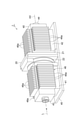
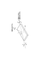
図2及び図3に示されるように、アッテネータユニット7は、第1ウィンドウ対10と、回転保持部20と、第2ウィンドウ対30と、筐体40と、を備えている。第1ウィンドウ対10及び第2ウィンドウ対30は、共通の筐体40内に配置されている。第1ウィンドウ対10、回転保持部20及び第2ウィンドウ対30は、筐体40に対して固定されており、筐体40と共に1つのユニットを構成している。
As shown in FIGS. 2 and 3, the attenuator unit 7 includes a first window pair 10, a rotation holding unit 20, a second window pair 30, and a housing 40. The first window pair 10 and the second window pair 30 are arranged in a common housing 40. The first window pair 10, the rotation holding portion 20, and the second window pair 30 are fixed to the housing 40 and form one unit together with the housing 40.
筐体40は、第1ウィンドウ対10を収容する箱状の第1部分41と、第2ウィンドウ対30を収容する箱状の第2部分42と、を有している。第1部分41には、レーザ光Lが入射する入射部43が形成されており、第2部分42には、レーザ光Lが出射する出射部44が形成されている。回転保持部20は、第1部分41と第2部分42との間に配置されている。回転保持部20により筐体40の一部が構成されているとみなすこともできる。
The housing 40 has a box-shaped first portion 41 accommodating the first window pair 10 and a box-shaped second portion 42 accommodating the second window pair 30. The first portion 41 is formed with an incident portion 43 into which the laser beam L is incident, and the second portion 42 is formed with an exit portion 44 from which the laser beam L is emitted. The rotation holding portion 20 is arranged between the first portion 41 and the second portion 42. It can also be considered that a part of the housing 40 is formed by the rotation holding portion 20.
第1部分41、第2部分42及び回転保持部20は、板部材45上に配置されている。第1部分41及び第2部分42の外面には、放熱構造46が設けられている。この例では、放熱構造46は、光軸AXに平行な方向に沿って並ぶ複数の板状の放熱フィン(ダンパー)46aによって構成されており、第1部分41の外面及び第2部分42の外面に設けられている。
The first portion 41, the second portion 42, and the rotation holding portion 20 are arranged on the plate member 45. A heat dissipation structure 46 is provided on the outer surfaces of the first portion 41 and the second portion 42. In this example, the heat dissipation structure 46 is composed of a plurality of plate-shaped heat dissipation fins (dampers) 46a arranged along a direction parallel to the optical axis AX, and is composed of an outer surface of the first portion 41 and an outer surface of the second portion 42. It is provided in.
第1ウィンドウ対10は、光軸AX上において互いに向かい合う一対の第1ウィンドウ11を有している。各第1ウィンドウ11には、入射部43を通過したレーザ光Lが光軸AXに沿って入射する。各第1ウィンドウ11は、例えば、セレン化亜鉛(ZnSe)により矩形板状に形成されている。
The first window pair 10 has a pair of first windows 11 facing each other on the optical axis AX. The laser beam L that has passed through the incident portion 43 is incident on each first window 11 along the optical axis AX. Each first window 11 is formed in a rectangular plate shape by, for example, zinc selenide (ZnSe).
各第1ウィンドウ11は、互いに平行な一対の第1表面11aを含んでいる。一対の第1ウィンドウ11の一方の一対の第1表面11aは、光軸AXに対して、一対の第1ウィンドウ11の他方の一対の第1表面11aとは反対側に傾いている。すなわち、一対の第1ウィンドウ11は、略逆V字状に配置されている。この例では、一対の第1ウィンドウ11は、光軸AXに直交する平面に関して面対称に配置されている。
Each first window 11 contains a pair of first surfaces 11a parallel to each other. One pair of first surfaces 11a of the pair of first windows 11 is tilted with respect to the optical axis AX so as to be opposite to the other pair of first surfaces 11a of the pair of first windows 11. That is, the pair of first windows 11 are arranged in a substantially inverted V shape. In this example, the pair of first windows 11 are arranged plane-symmetrically with respect to a plane orthogonal to the optical axis AX.
各第1表面11aは、光軸AXとブリュースタ角を成すように延在している。ブリュースタ角は、屈折率が互いに異なる物質の界面においてP偏光成分の反射率が0となる入射角である。P偏光は、反射面の法線と光軸AXとが含まれる面に対して振動方向が平行な偏光である。光が入射する物質の屈折率をnとすると、ブリュースタ角はtan-1nで表される。入射角がブリュースタ角となるように配置された面をブリュースタ面という。ブリュースタ面における光の減衰については後述する。
Each first surface 11a extends so as to form a brewer angle with the optical axis AX. The brewer angle is an incident angle at which the reflectance of the P-polarized light component becomes 0 at the interface between substances having different refractive indexes. P-polarized light is polarized light whose vibration direction is parallel to the surface including the normal of the reflecting surface and the optical axis AX. Assuming that the refractive index of the substance to which light is incident is n, the brewer angle is represented by tan -1 n. The surface arranged so that the incident angle is the brewer angle is called the brewer surface. The attenuation of light on the brewer surface will be described later.
回転保持部20は、ベース21と、回転ステージ22と、を有している。回転ステージ22は、光軸AX周りに回転可能となるようにベース21に固定されている。一対の第1ウィンドウ11は、回転ステージ22に固定されており、光軸AX周りに回転可能となっている。すなわち、回転保持部20は、第1ウィンドウ対10が光軸AX周りに回転可能となるように、第1ウィンドウ対10を保持している。一対の第1ウィンドウ11間の位置関係は固定されており、一対の第1ウィンドウ11は一体的に回転する。回転保持部20の動作は、制御部6により制御される。ベース21及び回転ステージ22には、ベース21及び回転ステージ22を光軸AXに沿って貫通する開口が形成されており、レーザ光Lは当該開口を通過する。
The rotation holding portion 20 has a base 21 and a rotation stage 22. The rotary stage 22 is fixed to the base 21 so as to be rotatable around the optical axis AX. The pair of first windows 11 are fixed to the rotation stage 22 and can rotate around the optical axis AX. That is, the rotation holding unit 20 holds the first window pair 10 so that the first window pair 10 can rotate around the optical axis AX. The positional relationship between the pair of first windows 11 is fixed, and the pair of first windows 11 rotate integrally. The operation of the rotation holding unit 20 is controlled by the control unit 6. The base 21 and the rotary stage 22 are formed with an opening that penetrates the base 21 and the rotary stage 22 along the optical axis AX, and the laser beam L passes through the opening.
第2ウィンドウ対30は、光軸AX上において互いに向かい合う一対の第2ウィンドウ31を有している。各第2ウィンドウ31には、第1ウィンドウ対10を透過したレーザ光Lが光軸AXに沿って入射する。各第2ウィンドウ31は、例えば、第1ウィンドウ11と同一の材料により、矩形板状に形成されている。
The second window pair 30 has a pair of second windows 31 facing each other on the optical axis AX. A laser beam L transmitted through the first window pair 10 is incident on each second window 31 along the optical axis AX. Each second window 31 is formed in a rectangular plate shape, for example, from the same material as the first window 11.
各第2ウィンドウ31は、互いに平行な一対の第2表面31aを含んでいる。一対の第2ウィンドウ31の一方の一対の第2表面31aは、光軸AXに対して、一対の第2ウィンドウ31の他方の一対の第2表面31aとは反対側に傾いている。すなわち、一対の第2ウィンドウ31は、略逆V字状に配置されている。この例では、一対の第2ウィンドウ31は、光軸AXに直交する平面に関して面対称に配置されている。各第2表面31aは、光軸AXとブリュースタ角を成すように延在している。一対の第2ウィンドウ31の位置は、筐体40内において固定されている。
Each second window 31 contains a pair of second surfaces 31a parallel to each other. One pair of second surfaces 31a of the pair of second windows 31 is tilted with respect to the optical axis AX so as to be opposite to the other pair of second surfaces 31a of the pair of second windows 31. That is, the pair of second windows 31 are arranged in a substantially inverted V shape. In this example, the pair of second windows 31 are arranged plane-symmetrically with respect to a plane orthogonal to the optical axis AX. Each second surface 31a extends so as to form a brewer angle with the optical axis AX. The positions of the pair of second windows 31 are fixed in the housing 40.
図4を参照しつつ、ブリュースタ面における光の減衰について説明する。図4に示されるように、入射角θがブリュースタ角となるブリュースタ面Bでは、入射光のP偏光成分が略100%透過する一方、S偏光成分は50.33%のみが透過して残りは反射する。したがって、第1ウィンドウ対10の4つの第1表面11aをレーザ光Lに通過させることで、P偏光成分を略100%透過させつつ、S偏光成分を6.4%程度にまで減衰させることができる。同様に、第2ウィンドウ対30の4つの第2表面31aをレーザ光Lに通過させることで、P偏光成分を略100%透過させつつ、S偏光成分を6.4%程度にまで減衰させることができる。
The attenuation of light on the brewer surface will be described with reference to FIG. As shown in FIG. 4, on the brewer surface B where the incident angle θ is the brewer angle, approximately 100% of the P-polarized light component of the incident light is transmitted, while only 50.33% of the S-polarized light component is transmitted. The rest are reflected. Therefore, by passing the four first surfaces 11a of the first window pair 10 through the laser beam L, the S-polarized light component can be attenuated to about 6.4% while transmitting approximately 100% of the P-polarized light component. can. Similarly, by passing the four second surfaces 31a of the second window pair 30 through the laser beam L, the S-polarized light component is attenuated to about 6.4% while transmitting approximately 100% of the P-polarized light component. Can be done.
レーザ光Lが第1ウィンドウ11を透過する際には屈折により光路にずれが生じるが、アッテネータ装置5では一対の第1ウィンドウ11が互いに反対側に傾くように配置されているため、一方の第1ウィンドウ11において生じた光路のずれが、他方の第1ウィンドウ11を通過する際に補正される。その結果、一対の第1ウィンドウ11を通過する前後で光軸AXの位置にずれが生じることがない。同様に、一対の第2ウィンドウ31を通過する前後で光軸AXの位置にずれが生じることがない。
When the laser beam L passes through the first window 11, the optical path shifts due to refraction. However, in the attenuator device 5, the pair of first windows 11 are arranged so as to be inclined to the opposite sides, so that one of them is the first. The deviation of the optical path generated in one window 11 is corrected when passing through the other first window 11. As a result, the position of the optical axis AX does not shift before and after passing through the pair of first windows 11. Similarly, the position of the optical axis AX does not shift before and after passing through the pair of second windows 31.
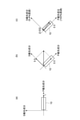
図5を参照しつつ、第1ウィンドウ対10を回転させた場合の透過成分の割合の変化について説明する。図5では、第1ウィンドウ対10が1つの要素として簡略化して示されている。図5(a)に示されるように、P偏光成分のみを有する光が第1ウィンドウ対10に入射すると、光の100%が透過する。この状態から、図5(b)に示されるように第1ウィンドウ対10を光軸AX周りに45度回転させると、入射光がP偏光成分とS偏光成分とに均等に分割される。すなわち、図5(a)におけるP偏光成分を1とすると、図5(b)ではP偏光成分及びS偏光成分が0.5ずつとなる。P偏光成分は略100%透過されるが、S偏光成分は6.4%に減衰されるため、図5(c)に示されるように、P偏光成分が0.5透過する一方、S偏光成分は0.032のみが透過する。
With reference to FIG. 5, the change in the ratio of the permeation component when the first window to 10 is rotated will be described. In FIG. 5, the first window to 10 is shown simplified as one element. As shown in FIG. 5A, when light having only a P polarization component is incident on the first window pair 10, 100% of the light is transmitted. From this state, when the first window pair 10 is rotated by 45 degrees around the optical axis AX as shown in FIG. 5 (b), the incident light is evenly divided into a P-polarized light component and an S-polarized light component. That is, assuming that the P-polarized light component in FIG. 5 (a) is 1, the P-polarized light component and the S-polarized light component are 0.5 each in FIG. 5 (b). The P-polarized light component is transmitted approximately 100%, but the S-polarized light component is attenuated to 6.4%. Therefore, as shown in FIG. 5 (c), the P-polarized light component transmits 0.5 while the S-polarized light component is transmitted. Only 0.032 of the component is transparent.
このように、第1ウィンドウ対10にP偏光成分のみが入射している状態から第1ウィンドウ対10を光軸AX周りに回転させると、P偏光成分が減少してS偏光成分が増加する。その結果、S偏光成分の大部分は反射されるため、透過光の強度を変化させることができる。すなわち、第1ウィンドウ対10を光軸AX周りに例えば0度から90度まで回転させることで、透過成分の割合を変化させ、透過光の強度を100%から6.4%まで連続的に変化させることができる。
As described above, when the first window pair 10 is rotated around the optical axis AX from the state where only the P polarization component is incident on the first window pair 10, the P polarization component decreases and the S polarization component increases. As a result, most of the S-polarized light component is reflected, so that the intensity of transmitted light can be changed. That is, by rotating the first window pair 10 around the optical axis AX, for example, from 0 degrees to 90 degrees, the ratio of transmitted components is changed, and the intensity of transmitted light is continuously changed from 100% to 6.4%. Can be made to.
一方、図5(c)に示されるように、S偏光成分の大部分が反射されるものの、残りの一部は反射されずに透過する。したがって、光が第1ウィンドウ対10を透過する際には、強度が減衰されると共に、偏光方向が回転する。
On the other hand, as shown in FIG. 5C, most of the S-polarized light component is reflected, but the remaining part is transmitted without being reflected. Therefore, when light passes through the first window pair 10, the intensity is attenuated and the polarization direction is rotated.
再び図1を参照して、λ/4位相素子8は、第1ウィンドウ対10及び第2ウィンドウ対30をこの順に通過した後にレーザ光Lが入射するように配置されている。すなわち、λ/4位相素子8は、レーザ光Lの進行方向において第2ウィンドウ対30の下流側に配置されている。λ/4位相素子8は、レーザ光Lの波長をλとすると、光学軸に平行な偏光成分と光学軸に直交する偏光成分との間にλ/4の位相差を与える。λ/4位相素子8は、例えば円偏光ミラーであり、入射したレーザ光Lを反射させつつ、レーザ光Lにλ/4の位相差を与える。
With reference to FIG. 1 again, the λ / 4 phase element 8 is arranged so that the laser beam L is incident after passing through the first window pair 10 and the second window pair 30 in this order. That is, the λ / 4 phase element 8 is arranged on the downstream side of the second window pair 30 in the traveling direction of the laser beam L. Assuming that the wavelength of the laser beam L is λ, the λ / 4 phase element 8 gives a phase difference of λ / 4 between the polarization component parallel to the optical axis and the polarization component orthogonal to the optical axis. The λ / 4 phase element 8 is, for example, a circularly polarized mirror, and gives a phase difference of λ / 4 to the laser beam L while reflecting the incident laser beam L.
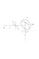
図6に示されるように、λ/4位相素子8は、直線偏光の光が入射した場合に、入射した光を円偏光に変化させる。より具体的には、λ/4位相素子8は、光軸AXに平行な方向から見た場合にλ/4位相素子8の光学軸OAに対して45度傾いた直線偏光の光が入射した場合に、入射した光を円偏光に変化させる。
As shown in FIG. 6, the λ / 4 phase element 8 changes the incident light into circularly polarized light when linearly polarized light is incident. More specifically, the λ / 4 phase element 8 is incident with linearly polarized light tilted 45 degrees with respect to the optical axis OA of the λ / 4 phase element 8 when viewed from a direction parallel to the optical axis AX. In some cases, the incident light is changed to circularly polarized light.
アッテネータ装置5では、第2ウィンドウ対30及びλ/4位相素子8により、加工対象物で反射したレーザ光Lである戻り光を抑制するアイソレータが構成されている。図7を参照しつつ、当該アイソレータについて説明する。図7では、第2ウィンドウ対30が1つの要素として簡略化して示されている。図7(a)では、レーザ光Lが第2ウィンドウ対30及びλ/4位相素子8をこの順に通過した後、加工対象物Wに照射される様子が示されている。図7(b)では、加工対象物Wで反射された戻り光Rがλ/4位相素子8を通過した後、第2ウィンドウ対30により反射されて除去される様子が示されている。なお、上記実施形態ではλ/4位相素子8が反射型の素子であったが、図7では、λ/4位相素子8が透過型の素子である例が示されている。いずれの場合においても、アイソレータとしての動作原理は共通である。
In the attenuator device 5, an isolator that suppresses the return light, which is the laser light L reflected by the object to be processed, is configured by the second window pair 30 and the λ / 4 phase element 8. The isolator will be described with reference to FIG. 7. In FIG. 7, the second window pair 30 is shown simplified as one element. FIG. 7A shows how the laser beam L is irradiated to the workpiece W after passing through the second window pair 30 and the λ / 4 phase element 8 in this order. FIG. 7B shows how the return light R reflected by the object W to be processed passes through the λ / 4 phase element 8 and then is reflected and removed by the second window pair 30. In the above embodiment, the λ / 4 phase element 8 is a reflection type element, but FIG. 7 shows an example in which the λ / 4 phase element 8 is a transmission type element. In either case, the operating principle as an isolator is common.
図7(a)に示されるように、第2ウィンドウ対30はP偏光成分を100%透過させてS偏光成分の大部分を反射させることから、第2ウィンドウ対30を透過したレーザ光Lは、P偏光成分のみを有する直線偏光状態であるとみなすことができる。ここで、第2ウィンドウ対30は、光軸AXに平行な方向から見た場合に、第2ウィンドウ対30を通過するP偏光成分の振動方向がλ/4位相素子8の光学軸OAに対して45度傾くように、配置されている。すなわち、光軸AXに平行な方向から見た場合に、各第2ウィンドウ31の法線(各第2表面31aの法線)と光学軸OAとの間の角度は、45度となっている。これにより、レーザ光Lがλ/4位相素子8により直線偏光から円偏光に変換され、円偏光のレーザ光Lが加工対象物Wに照射される。円偏光のレーザ光Lを加工対象物Wに照射することで、加工精度を高めることができる。
As shown in FIG. 7A, since the second window pair 30 transmits 100% of the P polarization component and reflects most of the S polarization component, the laser beam L transmitted through the second window pair 30 is , Can be regarded as a linearly polarized light state having only a P-polarized light component. Here, in the second window pair 30, when viewed from a direction parallel to the optical axis AX, the vibration direction of the P polarization component passing through the second window pair 30 is with respect to the optical axis OA of the λ / 4 phase element 8. It is arranged so as to be tilted at 45 degrees. That is, when viewed from a direction parallel to the optical axis AX, the angle between the normal of each second window 31 (normal of each second surface 31a) and the optical axis OA is 45 degrees. .. As a result, the laser beam L is converted from linearly polarized light to circularly polarized light by the λ / 4 phase element 8, and the circularly polarized laser beam L is applied to the object W to be processed. By irradiating the object W to be processed with the circularly polarized laser beam L, the processing accuracy can be improved.
図7(b)に示されるように、加工対象物Wに照射されたレーザ光Lの一部は加工対象物Wで反射され、位相差が180度変化した円偏光の戻り光Rとなる。戻り光Rにはλ/4位相素子8により90度の位相差が与えられる。λ/4位相素子8を透過した戻り光Rは、S偏光成分のみを有する直線偏光状態であるとみなすことができる。λ/4位相素子8を透過した戻り光Rは、第2ウィンドウ対30に入射する。第2ウィンドウ対30はS偏光成分の大部分を反射させるため、戻り光Rは第2ウィンドウ対30により反射され、光源2側へは戻らない。このように、第2ウィンドウ対30及びλ/4位相素子8は、戻り光Rを除去するアイソレータを構成している。戻り光Rの遮断は、加工対象物Wの反射率が高い場合に特に重要となる。
As shown in FIG. 7B, a part of the laser beam L irradiated on the object W to be processed is reflected by the object W to be processed, and becomes a circularly polarized return light R having a phase difference changed by 180 degrees. A phase difference of 90 degrees is given to the return light R by the λ / 4 phase element 8. The return light R transmitted through the λ / 4 phase element 8 can be regarded as a linearly polarized light state having only the S polarization component. The return light R transmitted through the λ / 4 phase element 8 is incident on the second window pair 30. Since the second window pair 30 reflects most of the S polarization component, the return light R is reflected by the second window pair 30 and does not return to the light source 2 side. As described above, the second window pair 30 and the λ / 4 phase element 8 form an isolator that removes the return light R. Blocking the return light R is particularly important when the reflectance of the workpiece W is high.
図8は、回転保持部20に入力されたパルス数と透過率との関係の例を示すグラフである。図8に示されるように、回転保持部20の回転ステージ22を駆動する駆動部にパルスが入力されて回転ステージ22が回転し、第1ウィンドウ対10が光軸AX周りに回転すると、アッテネータ装置5によるレーザ光Lの透過率が変化する。
FIG. 8 is a graph showing an example of the relationship between the number of pulses input to the rotation holding unit 20 and the transmittance. As shown in FIG. 8, when a pulse is input to the drive unit that drives the rotation stage 22 of the rotation holding unit 20, the rotation stage 22 rotates, and the first window pair 10 rotates around the optical axis AX, the attenuator device. The transmittance of the laser beam L according to No. 5 changes.
図8の例では、パルス数が19100である時点において、透過率が96%で最大となった。透過率が最大となる状態は、第1ウィンドウ対10の回転角度が第2ウィンドウ対30の回転角度と同一である状態、すなわち、第1ウィンドウ対10と第2ウィンドウ対30とが光軸AXに直交する平面に関して面対称に位置する状態に相当する。一方、第1ウィンドウ対10の回転角度が第2ウィンドウ対30の回転角度と90度異なる場合に、透過率は最小となる。なお、第1ウィンドウ対10の回転範囲は、60度程度の範囲内であってもよい。この場合、第1ウィンドウ対10の回転角度が第2ウィンドウ対30の回転角度と60度異なる場合に、透過率が最小となってもよい。
In the example of FIG. 8, when the number of pulses was 19100, the transmittance reached the maximum at 96%. The state in which the transmittance is maximized is a state in which the rotation angle of the first window to 10 is the same as the rotation angle of the second window to 30, that is, the optical axis AX is that the first window to 10 and the second window to 30 are. Corresponds to the state of being positioned plane-symmetrically with respect to the plane orthogonal to. On the other hand, when the rotation angle of the first window pair 10 differs from the rotation angle of the second window pair 30 by 90 degrees, the transmittance becomes the minimum. The rotation range of the first window to 10 may be within a range of about 60 degrees. In this case, the transmittance may be minimized when the rotation angle of the first window pair 10 differs from the rotation angle of the second window pair 30 by 60 degrees.
上述したとおり、レーザ加工装置1では、ミラー3により直線偏光に変換されたレーザ光Lが第1ウィンドウ対10に入射する。第1ウィンドウ対10に入射する直線偏光のレーザ光Lの偏光方向は、光軸AXに平行な方向から見た場合に、各第2ウィンドウ31の法線方向と一致している。すなわち、第1ウィンドウ対10に入射する直線偏光のレーザ光Lの偏光方向は、光軸AXに平行な方向から見た場合に、λ/4位相素子8の光学軸OAに対して45度傾いている。
As described above, in the laser processing apparatus 1, the laser beam L converted into linearly polarized light by the mirror 3 is incident on the first window pair 10. The polarization direction of the linearly polarized laser beam L incident on the first window pair 10 coincides with the normal direction of each second window 31 when viewed from a direction parallel to the optical axis AX. That is, the polarization direction of the linearly polarized laser light L incident on the first window pair 10 is tilted 45 degrees with respect to the optical axis OA of the λ / 4 phase element 8 when viewed from a direction parallel to the optical axis AX. ing.
制御部6は、第1ウィンドウ対10の回転角度が目標強度に応じた回転角度となるように回転保持部20を制御する。この例では、制御部6は、図8のグラフに基づくテーブルを記憶部に記憶している。当該テーブルは、第1ウィンドウ対10の回転角度と第1ウィンドウ対10及び第2ウィンドウ対30によるレーザ光Lの減衰率との関係を表す。制御部6は、当該テーブルに基づいて、第1ウィンドウ対10の回転角度が目標強度に応じた回転角度となるように回転保持部20を制御する。
The control unit 6 controls the rotation holding unit 20 so that the rotation angle of the first window to 10 becomes a rotation angle according to the target strength. In this example, the control unit 6 stores the table based on the graph of FIG. 8 in the storage unit. The table shows the relationship between the rotation angle of the first window to 10 and the attenuation rate of the laser beam L by the first window to 10 and the second window to 30. Based on the table, the control unit 6 controls the rotation holding unit 20 so that the rotation angle of the first window to 10 becomes a rotation angle according to the target strength.
レーザ加工装置1は、光源2とアッテネータ装置5との間に配置され、アッテネータ装置5に入射するレーザ光Lの強度を検出するパワーメータを更に備えている。制御部6は、パワーメータにより検出されたレーザ光Lの検出強度、目標強度及び上記テーブルに基づいて、第1ウィンドウ対10の回転角度を決定する。目標強度は、例えば加工対象物Wに対するレーザ光Lの照射強度であり、ユーザにより設定される。
[作用及び効果] Thelaser processing device 1 is arranged between the light source 2 and the attenuator device 5, and further includes a power meter for detecting the intensity of the laser beam L incident on the attenuator device 5. The control unit 6 determines the rotation angle of the first window to 10 based on the detected intensity of the laser beam L detected by the power meter, the target intensity, and the above table. The target intensity is, for example, the irradiation intensity of the laser beam L on the object W to be processed, and is set by the user.
[Action and effect]
[作用及び効果] The
[Action and effect]
アッテネータ装置5では、レーザ光Lが、一対の第1ウィンドウ11及び一対の第2ウィンドウ31を通過する。各第1ウィンドウ11は、光軸AXとブリュースタ角を成すように延在する一対の第1表面11aを含んでおり、各第2ウィンドウ31は、光軸AXとブリュースタ角を成すように延在する一対の第2表面31aを含んでいる。したがって、レーザ光Lは、光軸AXとブリュースタ角を成すように延在する計8つの表面を通過する。これにより、レーザ光Lを減衰させることができる。また、回転保持部20により、第1ウィンドウ対10が光軸AX周りに回転可能に保持されている。これにより、第1ウィンドウ対10を回転させることで、レーザ光Lの減衰率を変化させることができる。特に、アッテネータ装置5では、レーザ光Lが計8つの表面において減衰されるため、減衰範囲を大きく確保することができ、減衰率を大きく変化させることができる。
In the attenuator device 5, the laser beam L passes through the pair of first windows 11 and the pair of second windows 31. Each first window 11 includes a pair of first surfaces 11a extending so as to form a brewer angle with the optical axis AX, and each second window 31 so as to form a brewer angle with the optical axis AX. It contains a pair of extending second surfaces 31a. Therefore, the laser beam L passes through a total of eight surfaces extending so as to form a brewer angle with the optical axis AX. As a result, the laser beam L can be attenuated. Further, the rotation holding portion 20 rotatably holds the first window pair 10 around the optical axis AX. Thereby, the attenuation rate of the laser beam L can be changed by rotating the first window pair 10. In particular, in the attenuator device 5, since the laser beam L is attenuated on a total of eight surfaces, a large attenuation range can be secured and the attenuation rate can be greatly changed.
また、第1ウィンドウ対10及び第2ウィンドウ対30をこの順に通過したレーザ光Lが、光学軸OAに平行な偏光成分と光学軸OAに直交する偏光成分との間にλ/4の位相差を与えるλ/4位相素子8に入射する。ここで、第2ウィンドウ対30は、光軸AXに平行な方向から見た場合に、第2ウィンドウ対30を透過するP偏光成分の振動方向がλ/4位相素子8の光学軸OAに対して45度傾くように、配置されている。これにより、第2ウィンドウ対30及びλ/4位相素子8がアイソレータとして機能し、戻り光Rを除去することができる。よって、アッテネータ装置5によれば、レーザ光Lを好適に減衰させることができると共に、戻り光Rを抑制することができる。また、第2ウィンドウ対30に代えて例えば波長板等の他の偏光素子をポラライザとして用いてアイソレータを構成する場合と比べて、レーザ光Lの利用効率を高めることが可能となる。また、第2ウィンドウ対30を省略し、第1ウィンドウ対10のみによってレーザ光Lを減衰させる場合、第1ウィンドウ対10の回転角度によってはアイソレータ機能を実現することができないが、アッテネータ装置5では、第1ウィンドウ対10及び第2ウィンドウ対30の2つのウィンドウ対を備えることで、アイソレータ機能を確実に実現することができる。また、他の減光手段として、波長板と偏光素子を用いるものがあるが、波長板の精度のばらつきが大きい、波長板のコーティングに損傷が生じ易いといった問題がある。これに対し、アッテネータ装置5では、そのような事態を回避することができる。
Further, the laser beam L passing through the first window pair 10 and the second window pair 30 in this order has a phase difference of λ / 4 between the polarization component parallel to the optical axis OA and the polarization component orthogonal to the optical axis OA. It is incident on the λ / 4 phase element 8 that gives. Here, in the second window pair 30, when viewed from a direction parallel to the optical axis AX, the vibration direction of the P polarization component transmitted through the second window pair 30 is with respect to the optical axis OA of the λ / 4 phase element 8. It is arranged so as to be tilted at 45 degrees. As a result, the second window pair 30 and the λ / 4 phase element 8 function as an isolator, and the return light R can be removed. Therefore, according to the attenuator device 5, the laser beam L can be suitably attenuated and the return light R can be suppressed. Further, it is possible to improve the utilization efficiency of the laser beam L as compared with the case where another polarizing element such as a wave plate is used as a polarizer instead of the second window pair 30 to form an isolator. Further, when the second window pair 30 is omitted and the laser beam L is attenuated only by the first window pair 10, the isolator function cannot be realized depending on the rotation angle of the first window pair 10, but the attenuator device 5 does not. , The isolator function can be surely realized by providing two window pairs, a first window pair 10 and a second window pair 30. Further, as another dimming means, there is one that uses a wave plate and a polarizing element, but there are problems that the accuracy of the wave plate varies widely and the coating of the wave plate is easily damaged. On the other hand, in the attenuator device 5, such a situation can be avoided.
第1ウィンドウ対10、回転保持部20及び第2ウィンドウ対30が、互いに固定され、1つのユニットを構成している。これにより、アッテネータ装置5の取り扱いを容易化することができる。
The first window pair 10, the rotation holding unit 20 and the second window pair 30 are fixed to each other to form one unit. This makes it possible to facilitate the handling of the attenuator device 5.
第1ウィンドウ対10及び第2ウィンドウ対30が、共通の筐体40内に配置されている。これにより、アッテネータ装置5の取り扱いを一層容易化することができる。また、第1ウィンドウ対10及び第2ウィンドウ対30で反射されたレーザ光Lを筐体40内に留めることができる。
The first window to 10 and the second window to 30 are arranged in a common housing 40. This makes it possible to further facilitate the handling of the attenuator device 5. Further, the laser beam L reflected by the first window pair 10 and the second window pair 30 can be retained in the housing 40.
筐体40には、放熱構造46が設けられている。これにより、第1ウィンドウ対10及び第2ウィンドウ対30で反射されたレーザ光Lにより生じる熱を効果的に放熱することができる。
The housing 40 is provided with a heat dissipation structure 46. As a result, the heat generated by the laser beam L reflected by the first window pair 10 and the second window pair 30 can be effectively dissipated.
制御部6が、第1ウィンドウ対10の回転角度と第1ウィンドウ対10及び第2ウィンドウ対30によるレーザ光Lの減衰率との関係に基づいて、第1ウィンドウ対10の回転角度が目標強度に応じた回転角度となるように回転保持部20を制御する。これにより、レーザ光Lの減衰率を目標強度に応じた減衰率に確実に調整することができる。また、例えばユーザが第1ウィンドウ対10の回転角度を手動で調整する場合と比べて、操作性及び再現性を向上することができる。
Based on the relationship between the rotation angle of the first window to 10 and the attenuation rate of the laser beam L by the first window to 10 and the second window to 30, the control unit 6 sets the rotation angle of the first window to 10 as the target intensity. The rotation holding unit 20 is controlled so that the rotation angle corresponds to the above. As a result, the attenuation rate of the laser beam L can be reliably adjusted to the attenuation rate according to the target intensity. Further, the operability and reproducibility can be improved as compared with the case where the user manually adjusts the rotation angle of the first window to 10, for example.
本開示は、上記実施形態に限られない。例えば、各構成の材料及び形状には、上述した材料及び形状に限らず、様々な材料及び形状を採用することができる。
This disclosure is not limited to the above embodiment. For example, as the material and shape of each configuration, not only the above-mentioned material and shape but also various materials and shapes can be adopted.
1…レーザ加工装置、2…光源、5…アッテネータ装置、6…制御部、8…λ/4位相素子、10…第1ウィンドウ対、11…第1ウィンドウ、11a…第1表面、20…回転保持部、30…第2ウィンドウ対、31…第2ウィンドウ、31a…第2表面、40…筐体、46…放熱構造、AX…光軸、L…レーザ光、OA…光学軸。
1 ... Laser processing device, 2 ... Light source, 5 ... Attenuator device, 6 ... Control unit, 8 ... λ / 4 phase element, 10 ... First window pair, 11 ... First window, 11a ... First surface, 20 ... Rotation Holding part, 30 ... second window pair, 31 ... second window, 31a ... second surface, 40 ... housing, 46 ... heat dissipation structure, AX ... optical axis, L ... laser light, OA ... optical axis.
Claims (7)
- 光軸に沿ってレーザ光が入射する一対の第1ウィンドウを有する第1ウィンドウ対であって、前記一対の第1ウィンドウの各々は、前記光軸とブリュースタ角を成すように延在する一対の第1表面を含み、前記一対の第1ウィンドウの一方の前記一対の第1表面は、前記光軸に対して、前記一対の第1ウィンドウの他方の前記一対の第1表面とは反対側に傾いている、前記第1ウィンドウ対と、
前記第1ウィンドウ対が前記光軸周りに回転可能となるように前記第1ウィンドウ対を保持する回転保持部と、
一対の第2ウィンドウを有する第2ウィンドウ対であって、前記一対の第2ウィンドウの各々は、前記光軸とブリュースタ角を成すように延在する一対の第2表面を含み、前記一対の第2ウィンドウの一方の前記一対の第2表面は、前記光軸に対して、前記一対の第2ウィンドウの他方の前記一対の第2表面とは反対側に傾いている、前記第2ウィンドウ対と、
前記第1ウィンドウ対及び前記第2ウィンドウ対をこの順に通過した後に前記レーザ光が入射するように配置され、前記レーザ光の波長をλとすると、光学軸に平行な偏光成分と前記光学軸に直交する偏光成分との間にλ/4の位相差を与えるλ/4位相素子と、を備え、
前記第2ウィンドウ対は、前記光軸に平行な方向から見た場合に、前記第2ウィンドウ対を透過するP偏光成分の振動方向が前記λ/4位相素子の前記光学軸に対して45度傾くように、配置されている、アッテネータ装置。 A pair of first windows having a pair of first windows in which laser light is incident along the optical axis, each of the pair of first windows extending so as to form a brewer angle with the optical axis. The pair of first surfaces of one of the pair of first windows is opposite to the optical axis of the other of the pair of first windows. With the first window pair, which is tilted toward
A rotation holding portion that holds the first window pair so that the first window pair can rotate about the optical axis.
A second window pair having a pair of second windows, each of the pair of second windows comprising a pair of second surfaces extending to form a brewer angle with the optical axis. The pair of second windows of one of the second windows is tilted with respect to the optical axis on the opposite side of the pair of second surfaces of the pair of second windows. When,
The laser beam is arranged so as to be incident after passing through the first window pair and the second window pair in this order, and when the wavelength of the laser beam is λ, the polarization component parallel to the optical axis and the optical axis are present. It comprises a λ / 4 phase element that provides a λ / 4 phase difference with the orthogonal polarization components.
In the second window pair, when viewed from a direction parallel to the optical axis, the vibration direction of the P-polarized light component transmitted through the second window pair is 45 degrees with respect to the optical axis of the λ / 4 phase element. An attenuator device that is arranged to tilt. - 前記第1ウィンドウ対、前記回転保持部及び前記第2ウィンドウ対は、互いに固定され、1つのユニットを構成している、請求項1に記載のアッテネータ装置。 The attenuator device according to claim 1, wherein the first window pair, the rotation holding portion, and the second window pair are fixed to each other to form one unit.
- 前記第1ウィンドウ対及び前記第2ウィンドウ対は、共通の筐体内に配置されている、請求項1又は2に記載のアッテネータ装置。 The attenuator device according to claim 1 or 2, wherein the first window pair and the second window pair are arranged in a common housing.
- 前記筐体には、放熱構造が設けられている、請求項3に記載のアッテネータ装置。 The attenuator device according to claim 3, wherein the housing is provided with a heat dissipation structure.
- 前記第1ウィンドウ対の回転角度が目標強度に応じた回転角度となるように前記回転保持部を制御する制御部を更に備える、請求項1~4のいずれか一項に記載のアッテネータ装置。 The attenuator device according to any one of claims 1 to 4, further comprising a control unit that controls the rotation holding unit so that the rotation angle of the first window pair becomes a rotation angle according to the target strength.
- 前記制御部は、前記第1ウィンドウ対の回転角度と前記第1ウィンドウ対及び前記第2ウィンドウ対による前記レーザ光の減衰率との関係に基づいて、前記第1ウィンドウ対の回転角度が目標強度に応じた回転角度となるように前記回転保持部を制御する、請求項5に記載のアッテネータ装置。 In the control unit, the rotation angle of the first window pair is the target intensity based on the relationship between the rotation angle of the first window pair and the attenuation rate of the laser light by the first window pair and the second window pair. The attenuator device according to claim 5, wherein the rotation holding unit is controlled so as to have a rotation angle corresponding to the above.
- 前記レーザ光を出力する光源と、
請求項1~6のいずれか一項に記載のアッテネータ装置と、を備えるレーザ加工装置。 The light source that outputs the laser beam and
A laser processing apparatus comprising the attenuator apparatus according to any one of claims 1 to 6.
Priority Applications (4)
| Application Number | Priority Date | Filing Date | Title |
|---|---|---|---|
| US18/010,272 US20240033849A1 (en) | 2020-07-21 | 2021-04-19 | Attenuator device and laser processing apparatus |
| EP21845529.3A EP4113190A4 (en) | 2020-07-21 | 2021-04-19 | Attenuator device and laser processing apparatus |
| CN202180060829.9A CN116157224A (en) | 2020-07-21 | 2021-04-19 | Attenuator device and laser processing device |
| KR1020227038238A KR20230039597A (en) | 2020-07-21 | 2021-04-19 | Attenuator device and laser processing device |
Applications Claiming Priority (2)
| Application Number | Priority Date | Filing Date | Title |
|---|---|---|---|
| JP2020-124684 | 2020-07-21 | ||
| JP2020124684A JP2022021215A (en) | 2020-07-21 | 2020-07-21 | Attenuator device and laser processing device |
Publications (1)
| Publication Number | Publication Date |
|---|---|
| WO2022018917A1 true WO2022018917A1 (en) | 2022-01-27 |
Family
ID=79729321
Family Applications (1)
| Application Number | Title | Priority Date | Filing Date |
|---|---|---|---|
| PCT/JP2021/015881 WO2022018917A1 (en) | 2020-07-21 | 2021-04-19 | Attenuator device and laser processing apparatus |
Country Status (7)
| Country | Link |
|---|---|
| US (1) | US20240033849A1 (en) |
| EP (1) | EP4113190A4 (en) |
| JP (1) | JP2022021215A (en) |
| KR (1) | KR20230039597A (en) |
| CN (1) | CN116157224A (en) |
| TW (1) | TW202205766A (en) |
| WO (1) | WO2022018917A1 (en) |
Citations (6)
| Publication number | Priority date | Publication date | Assignee | Title |
|---|---|---|---|---|
| US3655268A (en) | 1970-06-01 | 1972-04-11 | Sylvania Electric Prod | Laser beam attenuator |
| JPS4916000Y1 (en) * | 1970-03-09 | 1974-04-22 | ||
| JPS59228207A (en) * | 1983-05-26 | 1984-12-21 | ライノタイプ・ゲゼルシャフト・ミット・ベシュレンクタ−・ハフツング | Variable laser beam damper |
| JPH11258526A (en) * | 1998-03-16 | 1999-09-24 | Hamamatsu Photonics Kk | Light quantity adjusting method/device |
| JP2007225905A (en) * | 2006-02-23 | 2007-09-06 | Asahi Glass Co Ltd | Optical isolator and bidirectional optical transmitting/receiving apparatus |
| CN103984112A (en) * | 2014-04-23 | 2014-08-13 | 深圳市大族激光科技股份有限公司 | Reflecting type optical isolator and laser machining equipment with the same |
Family Cites Families (2)
| Publication number | Priority date | Publication date | Assignee | Title |
|---|---|---|---|---|
| AUPS023002A0 (en) * | 2002-01-31 | 2002-02-21 | Q-Vis Limited | Variable attenuator |
| JP3655268B2 (en) | 2002-08-26 | 2005-06-02 | 株式会社東芝 | Fuel cell power plant |
-
2020
- 2020-07-21 JP JP2020124684A patent/JP2022021215A/en active Pending
-
2021
- 2021-04-19 KR KR1020227038238A patent/KR20230039597A/en active Search and Examination
- 2021-04-19 CN CN202180060829.9A patent/CN116157224A/en active Pending
- 2021-04-19 WO PCT/JP2021/015881 patent/WO2022018917A1/en active Application Filing
- 2021-04-19 EP EP21845529.3A patent/EP4113190A4/en active Pending
- 2021-04-19 US US18/010,272 patent/US20240033849A1/en active Pending
- 2021-04-30 TW TW110115747A patent/TW202205766A/en unknown
Patent Citations (6)
| Publication number | Priority date | Publication date | Assignee | Title |
|---|---|---|---|---|
| JPS4916000Y1 (en) * | 1970-03-09 | 1974-04-22 | ||
| US3655268A (en) | 1970-06-01 | 1972-04-11 | Sylvania Electric Prod | Laser beam attenuator |
| JPS59228207A (en) * | 1983-05-26 | 1984-12-21 | ライノタイプ・ゲゼルシャフト・ミット・ベシュレンクタ−・ハフツング | Variable laser beam damper |
| JPH11258526A (en) * | 1998-03-16 | 1999-09-24 | Hamamatsu Photonics Kk | Light quantity adjusting method/device |
| JP2007225905A (en) * | 2006-02-23 | 2007-09-06 | Asahi Glass Co Ltd | Optical isolator and bidirectional optical transmitting/receiving apparatus |
| CN103984112A (en) * | 2014-04-23 | 2014-08-13 | 深圳市大族激光科技股份有限公司 | Reflecting type optical isolator and laser machining equipment with the same |
Non-Patent Citations (1)
| Title |
|---|
| See also references of EP4113190A4 |
Also Published As
| Publication number | Publication date |
|---|---|
| EP4113190A1 (en) | 2023-01-04 |
| TW202205766A (en) | 2022-02-01 |
| CN116157224A (en) | 2023-05-23 |
| US20240033849A1 (en) | 2024-02-01 |
| JP2022021215A (en) | 2022-02-02 |
| EP4113190A4 (en) | 2024-04-10 |
| KR20230039597A (en) | 2023-03-21 |
Similar Documents
| Publication | Publication Date | Title |
|---|---|---|
| US4778263A (en) | Variable laser attenuator | |
| US4908493A (en) | Method and apparatus for optimizing the efficiency and quality of laser material processing | |
| US7259914B2 (en) | Attenuator for high-power unpolarized laser beams | |
| US5223956A (en) | Optical beam scanners for imaging applications | |
| US6061138A (en) | Optical exposure systems and processes for alignment of liquid crystals | |
| KR102454294B1 (en) | Carbon Monoxide Laser Machining System | |
| JP3107734B2 (en) | Method and apparatus for optical separation | |
| US7706069B2 (en) | Attenuator for high-power unpolarized laser beams | |
| US4914664A (en) | Tunable dye laser with suppressed frequency shift anomalies | |
| TWI457601B (en) | Polarization azimuth adjustment device and laser processing apparatus | |
| US20180231790A1 (en) | Linear polarization of a laser beam | |
| US8553311B2 (en) | Method for accomplishing high-speed intensity variation of a polarized output laser beam | |
| WO2022018917A1 (en) | Attenuator device and laser processing apparatus | |
| CN112099243A (en) | Laser power attenuator | |
| JPH09146020A (en) | Polarization-nondependent variable wavelength device and polarization axis rotary mirror | |
| JPH09197302A (en) | Light intensity controller | |
| JP6542473B2 (en) | Nonlinear frequency conversion device | |
| JP4465267B2 (en) | Polarized light illumination device | |
| JP2003066375A (en) | Device and method for branching laser beam | |
| CN213023791U (en) | Laser power attenuator | |
| CN110869825A (en) | Polarizer device and EUV radiation generating apparatus having a polarizer device | |
| JP2000305119A (en) | Optical device for wavelength conversion | |
| JPH0792558B2 (en) | Laser beam attenuator | |
| JPS6147402B2 (en) | ||
| JP2022021215A5 (en) |
Legal Events
| Date | Code | Title | Description |
|---|---|---|---|
| 121 | Ep: the epo has been informed by wipo that ep was designated in this application |
Ref document number: 21845529 Country of ref document: EP Kind code of ref document: A1 |
|
| ENP | Entry into the national phase |
Ref document number: 2021845529 Country of ref document: EP Effective date: 20220928 |
|
| WWE | Wipo information: entry into national phase |
Ref document number: 18010272 Country of ref document: US |
|
| NENP | Non-entry into the national phase |
Ref country code: DE |