WO2022014426A1 - 燃料噴射弁 - Google Patents
燃料噴射弁 Download PDFInfo
- Publication number
- WO2022014426A1 WO2022014426A1 PCT/JP2021/025563 JP2021025563W WO2022014426A1 WO 2022014426 A1 WO2022014426 A1 WO 2022014426A1 JP 2021025563 W JP2021025563 W JP 2021025563W WO 2022014426 A1 WO2022014426 A1 WO 2022014426A1
- Authority
- WO
- WIPO (PCT)
- Prior art keywords
- injection hole
- injection
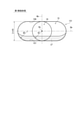
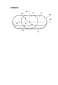
- radius
- fuel
- valve
- Prior art date
- Legal status (The legal status is an assumption and is not a legal conclusion. Google has not performed a legal analysis and makes no representation as to the accuracy of the status listed.)
- Ceased
Links
Images












Classifications
-
- F—MECHANICAL ENGINEERING; LIGHTING; HEATING; WEAPONS; BLASTING
- F02—COMBUSTION ENGINES; HOT-GAS OR COMBUSTION-PRODUCT ENGINE PLANTS
- F02M—SUPPLYING COMBUSTION ENGINES IN GENERAL WITH COMBUSTIBLE MIXTURES OR CONSTITUENTS THEREOF
- F02M61/00—Fuel-injectors not provided for in groups F02M39/00 - F02M57/00 or F02M67/00
- F02M61/16—Details not provided for in, or of interest apart from, the apparatus of groups F02M61/02 - F02M61/14
- F02M61/18—Injection nozzles, e.g. having valve seats; Details of valve member seated ends, not otherwise provided for
- F02M61/1806—Injection nozzles, e.g. having valve seats; Details of valve member seated ends, not otherwise provided for characterised by the arrangement of discharge orifices, e.g. orientation or size
- F02M61/1813—Discharge orifices having different orientations with respect to valve member direction of movement, e.g. orientations being such that fuel jets emerging from discharge orifices collide with each other
-
- F—MECHANICAL ENGINEERING; LIGHTING; HEATING; WEAPONS; BLASTING
- F02—COMBUSTION ENGINES; HOT-GAS OR COMBUSTION-PRODUCT ENGINE PLANTS
- F02M—SUPPLYING COMBUSTION ENGINES IN GENERAL WITH COMBUSTIBLE MIXTURES OR CONSTITUENTS THEREOF
- F02M61/00—Fuel-injectors not provided for in groups F02M39/00 - F02M57/00 or F02M67/00
- F02M61/04—Fuel-injectors not provided for in groups F02M39/00 - F02M57/00 or F02M67/00 having valves, e.g. having a plurality of valves in series
- F02M61/10—Other injectors with elongated valve bodies, i.e. of needle-valve type
-
- F—MECHANICAL ENGINEERING; LIGHTING; HEATING; WEAPONS; BLASTING
- F02—COMBUSTION ENGINES; HOT-GAS OR COMBUSTION-PRODUCT ENGINE PLANTS
- F02M—SUPPLYING COMBUSTION ENGINES IN GENERAL WITH COMBUSTIBLE MIXTURES OR CONSTITUENTS THEREOF
- F02M61/00—Fuel-injectors not provided for in groups F02M39/00 - F02M57/00 or F02M67/00
- F02M61/16—Details not provided for in, or of interest apart from, the apparatus of groups F02M61/02 - F02M61/14
- F02M61/18—Injection nozzles, e.g. having valve seats; Details of valve member seated ends, not otherwise provided for
- F02M61/1806—Injection nozzles, e.g. having valve seats; Details of valve member seated ends, not otherwise provided for characterised by the arrangement of discharge orifices, e.g. orientation or size
- F02M61/1833—Discharge orifices having changing cross sections, e.g. being divergent
-
- F—MECHANICAL ENGINEERING; LIGHTING; HEATING; WEAPONS; BLASTING
- F02—COMBUSTION ENGINES; HOT-GAS OR COMBUSTION-PRODUCT ENGINE PLANTS
- F02M—SUPPLYING COMBUSTION ENGINES IN GENERAL WITH COMBUSTIBLE MIXTURES OR CONSTITUENTS THEREOF
- F02M61/00—Fuel-injectors not provided for in groups F02M39/00 - F02M57/00 or F02M67/00
- F02M61/16—Details not provided for in, or of interest apart from, the apparatus of groups F02M61/02 - F02M61/14
- F02M61/18—Injection nozzles, e.g. having valve seats; Details of valve member seated ends, not otherwise provided for
- F02M61/1806—Injection nozzles, e.g. having valve seats; Details of valve member seated ends, not otherwise provided for characterised by the arrangement of discharge orifices, e.g. orientation or size
- F02M61/184—Discharge orifices having non circular sections
-
- F—MECHANICAL ENGINEERING; LIGHTING; HEATING; WEAPONS; BLASTING
- F02—COMBUSTION ENGINES; HOT-GAS OR COMBUSTION-PRODUCT ENGINE PLANTS
- F02M—SUPPLYING COMBUSTION ENGINES IN GENERAL WITH COMBUSTIBLE MIXTURES OR CONSTITUENTS THEREOF
- F02M61/00—Fuel-injectors not provided for in groups F02M39/00 - F02M57/00 or F02M67/00
- F02M61/16—Details not provided for in, or of interest apart from, the apparatus of groups F02M61/02 - F02M61/14
- F02M61/18—Injection nozzles, e.g. having valve seats; Details of valve member seated ends, not otherwise provided for
- F02M61/1886—Details of valve seats not covered by groups F02M61/1866 - F02M61/188
Definitions
- This disclosure relates to a fuel injection valve.
- Patent Document 1 a technique for improving spraying by devising the shape of the injection hole of the fuel injection valve has been known.
- the deposit on the inner wall of the injection hole is accumulated by flattening the cross-sectional shape of the injection hole so that the area of the portion of the inner wall of the injection hole where fuel does not flow is small. It is suppressing.
- Patent Document 2 describes that by making the injection hole flat, the thinning of the liquid film is promoted, and atomization and low penetration can be achieved.
- the fuel is placed along the inner wall of the flat injection hole to promote the thinning of the liquid film, and the atomization and low penetration are realized.
- the total amount of the wall surface Wet by atomization or low penetration, no consideration is given to the relationship between the adhesion state of the wall surface Wet and the penetration.
- the fuel after adhesion is quickly evaporated to suppress the bright flame by reducing the residual fuel on the wall surface and reduce the penetration. It is thought that it can be done.
- a thin and wide wall surface Wet is required to be adhered. Therefore, it is necessary to improve the dispersibility of the spray and reduce the variation in fuel concentration and particle size.
- the purpose of the present disclosure is to provide a fuel injection valve that realizes highly dispersed and highly homogeneous spraying.
- the fuel injection valve of the present disclosure includes a nozzle, a needle, and a drive unit.
- the nozzle is provided around the valve shaft, and is a nozzle cylinder that forms a fuel passage inside, a nozzle bottom that closes one end of the nozzle cylinder, "the surface of the nozzle bottom on the nozzle cylinder side” and “what is the nozzle cylinder”. It has a plurality of injection holes that connect to the "opposite surface” and inject fuel in the fuel passage, and an annular valve seat formed around the injection holes in the "nozzle cylinder side surface at the bottom of the nozzle”. ..
- the needle is provided inside the nozzle so that it can reciprocate along the valve shaft, and when it comes into contact with the valve seat, it closes the injection hole, and when it separates from the valve seat, it opens the injection hole.
- the drive unit can move the needle in the valve opening direction or the valve closing direction.
- the injection hole is formed on the "inlet opening on the surface of the nozzle bottom on the nozzle cylinder side" and the "surface on the side of the nozzle bottom opposite to the nozzle cylinder", and the area is the area of the inlet opening. Has a larger outlet opening.
- One or more of the plurality of injection holes is a "flat injection hole” in which the outlet opening has a major axis and a minor axis.
- the flat injection hole further includes one or more "specific flat injection holes”.
- the long axis of the specific flat injection hole is orthogonal to the plane parallel to the valve axis, including the injection hole axis connecting the center of the inlet opening and the center of the outlet opening. Further, the specific flat injection hole has a flat surface portion facing the inner wall with a long axis interposed therebetween.
- the radius of curvature of the long axis direction end of the inlet opening is the first radius of curvature
- the radius of curvature of the long axis direction end of the exit opening is the second radius of curvature.
- the ratio of the second radius of curvature to the first radius of curvature is defined as the radius of curvature ratio.
- the radius of curvature ratio is in the range of 40% to 100%, more preferably in the range of 50% to 90%.
- the radius of curvature ratio of the outlet opening to the inlet opening is in the range of 40% to 100%, so that the liquid film in the injection hole forming the spray is homogeneous. Can be. Therefore, highly dispersed and highly homogeneous spray can be realized.
- a plurality of injection holes are arranged symmetrically with respect to a reference plane including a valve axis, and at least a pair of injection holes having a maximum injection hole angle, which is the angle of the injection hole axis with respect to the valve axis, is a specific flat injection. It constitutes a hole.
- FIG. 1 is a cross-sectional view showing the overall configuration of the fuel injection valve according to the present embodiment.
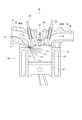
- FIG. 2 is a schematic view of a side-mounted engine on which a fuel injection valve according to the first, sixth to ninth embodiments is mounted.
- FIG. 3 is a view of FIG. 2 from the direction of arrow III.
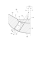
- FIG. 4 is an enlarged cross-sectional view of the IV portion of FIG. 1 (axial cross-sectional view of the injection hole).
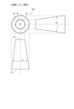
- FIG. 5 is a schematic three-view view showing the shape of the injection hole (tapered injection hole) of the comparative example.
- FIG. 6 is a schematic three-view view showing the shape of the injection hole (flat injection hole) of the present embodiment.
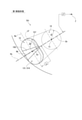
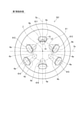
- FIG. 7 is a schematic view showing the injection hole arrangement (5 holes) of the fuel injection valve according to the first embodiment.
- FIG. 8 is an enlarged view of part VIII of FIG. 7.
- FIG. 9 is an axial cross-sectional view of the injection hole showing the inner wall on the side along which the fuel is in the injection.
- FIG. 10 is a schematic view showing the shape of the injection hole according to the first embodiment.
- FIG. 11 is a diagram illustrating liquid film homogeneity.
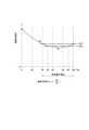
- FIG. 12 is a diagram showing the relationship between the radius of curvature ratio and the liquid film homogeneity.
- FIG. 13 is a schematic view showing the shape of the injection hole according to the second embodiment.
- FIG. 14 is a schematic view showing the shape of the injection hole according to the third embodiment.
- FIG. 15 is a schematic view showing the shape of the injection hole according to the fourth embodiment.
- FIG. 16 is a schematic view showing the shape of the injection hole according to the fifth embodiment.
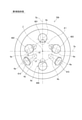
- FIG. 17 is a schematic view showing the injection hole arrangement (5 holes) of the fuel injection valve according to the sixth embodiment.
- FIG. 18 is a schematic view showing the injection hole arrangement (6 holes) of the fuel injection valve according to the seventh embodiment.
- FIG. 19 is a schematic view showing the injection hole arrangement (6 holes) of the fuel injection valve according to the eighth embodiment.
- FIG. 20 is a schematic view showing the injection hole arrangement (6 holes) of the fuel injection valve according to the ninth embodiment.
- FIG. 21 is a schematic diagram of a center-mounted engine equipped with a fuel injection valve according to the tenth and eleventh embodiments.
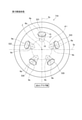
- FIG. 22 is a schematic view showing the injection hole arrangement (5 holes) of the fuel injection valve according to the tenth embodiment.
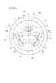
- FIG. 23 is a schematic view showing the injection hole arrangement (6 holes) of the fuel injection valve according to the eleventh embodiment.
- the fuel injection valve of the present embodiment is mounted on an engine such as a gasoline engine and injects fuel into the combustion chamber of the engine.
- the side-mounted engine 801 shown in FIGS. 2 and 3 includes a cylinder block 81, a piston 82, a cylinder head 90, an intake valve 95, an exhaust valve 96, and the like.
- a combustion chamber 83 is formed between the inner wall of the cylinder block 81, the wall surface of the cylinder head 90, and the piston 82. The volume of the combustion chamber 83 increases or decreases as the piston 82 reciprocates.
- the cylinder head 90 has an intake manifold 91 and an exhaust manifold 93.
- the intake manifold 91 is formed with an intake passage 92 that guides intake air to the combustion chamber 83.
- the exhaust manifold 93 is formed with an exhaust passage 94 that guides the exhaust generated in the combustion chamber 83 to the atmosphere side.
- the intake valve 95 can be opened and closed between the combustion chamber 83 and the intake passage 92.
- the exhaust valve 96 can be opened and closed between the combustion chamber 83 and the exhaust passage 94.
- the fuel injection valve 70 is provided so as to be inclined toward the cylinder block 81 side of the intake passage 92, that is, the side of the combustion chamber 83. Further, a spark plug 97 is provided between the intake valve 95 and the exhaust valve 96 of the cylinder head 90, that is, at a position corresponding to the center of the combustion chamber 83. The spark plug 97 is provided at a position where the fuel injected from the fuel injection valve 70 does not directly adhere to the spark plug 97, and at a position where the mixture of the fuel and the intake air can be ignited. As described above, the engine 801 is a direct injection type gasoline engine.
- the fuel injection valve 70 is provided so that a plurality of injection holes 13 are exposed on the radial outer portion of the combustion chamber 83. Fuel pressurized by a fuel pump (not shown) is supplied to the fuel injection valve 70. A conical fuel spray Fo is injected into the combustion chamber 83 from the plurality of injection holes 13 of the fuel injection valve 70.
- the engine 801 is provided with two intake valves 95 and an exhaust valve 96, respectively.
- the two intake valves 95 are provided at the two branched ends of the intake manifold 91 on the cylinder block 81 side, respectively.
- the two exhaust valves 96 are provided at the two branched ends of the exhaust manifold 93 on the cylinder block 81 side, respectively.
- the fuel injection valve 70 is mounted so that the valve shaft Z is along the central cross-section Se that includes the shaft of the cylinder block 81 and passes between the two intake valves 95 and between the two exhaust valves 96.
- the fuel injection valve 70 includes a nozzle 10, a housing 20, a needle 30, a movable core 37, a fixed core 41, a coil 45, springs 42, 43 and the like.
- the movable core 37, the fixed core 41 and the coil 45 function as a "driving unit" capable of moving the needle 30 in the valve opening direction or the valve closing direction.
- the nozzle 10 is provided around the valve shaft Z, and has a nozzle cylinder portion 11, a nozzle bottom portion 12, a plurality of injection holes 13, a valve seat 17, and the like.
- the substantially cylindrical nozzle cylinder portion 11 forms a fuel passage 100 inside.
- the nozzle bottom portion 12 closes one end of the nozzle cylinder portion 11.
- the plurality of injection holes 13 formed in the nozzle bottom 12 inject the fuel in the fuel passage 100.
- the valve seat 17 is formed in an annular shape around the injection hole 13 on the surface of the nozzle bottom 12 on the nozzle cylinder 11 side. The injection hole 13 will be described in detail later.
- the housing 20 has a first cylinder member 21, a second cylinder member 22, a third cylinder member 23, an inlet portion 24, and the like.
- the first cylinder member 21, the second cylinder member 22, and the third cylinder member 23 are all substantially cylindrical members, and are coaxial in the order of the first cylinder member 21, the second cylinder member 22, and the third cylinder member 23. They are arranged so that they are connected to each other.
- One end of the inlet portion 24 is connected to the end portion of the third cylinder member 23, and a pipe (not shown) is connected to the other end.
- a filter 25 for collecting foreign matter in the fuel is provided inside the inlet portion 24, a filter 25 for collecting foreign matter in the fuel is provided.
- a fuel passage 100 is formed inside the housing 20.
- the fuel flowing in from the inlet portion 24 passes through the fuel passage 100, passes through the inside of the nozzle cylinder portion 11, and is injected from the injection hole 13.
- the pressure of the fuel in the fuel passage 100 assumed when the fuel injection valve 70 of the present embodiment is used is, for example, about 20 MPa.
- the needle 30 is provided inside the nozzle 10 so as to be reciprocating along the valve shaft Z.
- the needle 30 has a rod-shaped needle body 301, a seat portion 31, a large diameter portion 32, a flange portion 34, and the like.
- the seat portion 31 is formed at the end portion of the needle body 301 on the nozzle 10 side and can come into contact with the valve seat 17.
- the large diameter portion 32 is formed in the vicinity of the seat portion 31 at the end of the needle body 301 on the valve seat 17 side.
- the outer diameter of the large diameter portion 32 is set to be larger than the outer diameter of the end portion of the needle body 301 on the valve seat 17 side.
- the large diameter portion 32 is formed so that the outer wall slides on the inner wall of the nozzle cylinder portion 11 of the nozzle 10.
- the fuel can flow through the notches 33 formed at a plurality of points in the circumferential direction of the outer wall of the large diameter portion 32.
- the flange portion 34 is formed so as to project outward from the end portion of the needle body 301 opposite to the seat portion 31.
- the needle 30 closes the injection hole 13 when the seat portion 31 comes into contact with the valve seat 17, and opens the injection hole 13 when the seat portion 31 separates from the valve seat 17.
- a valve opening direction the direction in which the needle 30 is separated from the valve seat 17
- a valve closing direction the direction in which the needle 30 abuts on the valve seat 17
- the movable core 37 is formed in a substantially cylindrical shape by a magnetic material such as ferritic stainless steel which has been subjected to magnetic stabilization treatment.
- the movable core 37 is provided inside the first cylinder member 21 and the second cylinder member 22 of the housing 20 so as to be relatively movable in the axial direction with respect to the needle body 301.
- the fixed core 41 is formed in a substantially cylindrical shape by a magnetic material such as ferritic stainless steel which has been subjected to magnetic stabilization treatment.
- the fixed core 41 is provided inside the second cylinder member 22 and the third cylinder member 23 of the housing 20 on the inlet portion 24 side with respect to the movable core 37.
- a cylindrical adjusting pipe 54 is press-fitted inside the fixed core 41.
- the spring 42 is, for example, a coil spring, and is provided between the adjusting pipe 54 inside the fixed core 41 and the flange portion 34 of the needle 30.
- the spring 42 together with the needle 30, urges the movable core 37 in the valve closing direction.
- the coil 45 is formed in a substantially cylindrical shape, and is provided so as to surround the radial outside of the second cylinder member 22 and the third cylinder member 23 in the housing 20 in particular. Further, on the radial outer side of the coil 45, a cylindrical holder 26 is provided so as to cover the coil 45.
- the spring 43 is, for example, a coil spring, and urges the movable core 37 toward the fixed core 41, that is, in the valve opening direction.
- the urging force of the spring 43 is smaller than the urging force of the spring 42. Therefore, when the coil 45 is not energized, the seat portion 31 of the needle 30 is pressed against the valve seat 17 by the spring 42, and the needle 30 is closed.
- the fuel flowing in from the inlet portion 24 is guided to the injection hole 13 through the fuel passage 100 between the inside of the fixed core 41 and the adjusting pipe 54, the inner wall of the needle 30 and the housing 20, and the inner wall of the tubular portion 11. Since the periphery of the movable core 37 and the needle 30 is filled with fuel when the fuel injection valve 70 is operated, the movable core 37 and the needle 30 can smoothly reciprocate in the axial direction inside the housing 20. Is.
- FIG. 4 shows an axial cross section of the injection hole 13 corresponding to the expanded cross section of the IV portion of FIG. Note that FIG. 4 omits the illustration of the needle 30.
- the nozzle 10 has a valve seat 17 and a sack wall surface 180 on the "face 121 on the nozzle cylinder 11 side of the nozzle bottom 12" which is the inlet side of the injection hole 13.
- the valve seat 17 is formed in an annular shape around the sack wall surface 180.
- the valve seat 17 is formed in a tapered shape so as to approach the valve shaft Z from the nozzle cylinder portion 11 side toward the sack wall surface 180 side.
- the sack wall surface 180 is recessed from the center of "the surface 121 on the nozzle cylinder 11 side of the nozzle bottom 12" to the side opposite to the nozzle cylinder 11, and forms a sack chamber 18 inside.
- the sack chamber 18 is formed between the sack wall surface 180 and the seat portion 31 of the needle 30.
- the injection hole 13 connects the sack wall surface 180, which is a part of the "face 121 on the nozzle cylinder 11 side of the nozzle bottom 12", and the "surface 122 of the nozzle bottom 12 opposite to the nozzle cylinder 11".
- the fuel in the fuel passage 100 is injected.
- the sack wall surface 180 and "the surface 122 of the nozzle bottom 12 opposite to the nozzle cylinder 11" are formed in a curved surface.
- the injection hole 13 has an inlet opening 14 formed on the sack wall surface 180 which is a surface of the nozzle bottom 12 on the nozzle cylinder 11 side, and an outlet formed on the surface 122 of the nozzle bottom 12 opposite to the nozzle cylinder 11. It has an opening 15. The area of the exit opening 15 is larger than the area of the entrance opening 14.
- injection axis Ho The straight line connecting the center Ci of the inlet opening 14 and the center Co of the outlet opening 15 is defined as "injection axis Ho".
- the injection hole shaft Ho does not always intersect the valve shaft Z. Therefore, assuming a virtual axis Zv that intersects the injection hole axis Ho and is parallel to the valve axis Z, the angle of the injection hole axis Ho with respect to the virtual axis Zv is defined as the “injection angle ⁇ ”.
- the distance between the center Ci of the inlet opening 14 and the center Co of the exit opening 15 as viewed from the VII arrow (that is, the valve axis Z direction) in FIG. 4 is defined as the “center-to-center projection distance P”. If the injection hole length L is substantially constant, the larger the projection distance P between the centers, the larger the injection hole angle ⁇ .
- the entrance opening 14 is a perfect circle, and its diameter is D.
- the ratio (L / D) of the injection hole length L and the inlet opening diameter D is set to 2.0 to 3.0. If (L / D) is smaller than 2.0, the injection direction is not stable. Further, when (L / D) is larger than 3.0, the injection direction speed decreases due to friction with the inner wall of the injection hole, and the atomization performance deteriorates.
- the shape of the injection hole of the fuel injection valve is defined so as to increase the spreading speed of the spray and to make the fuel thinner.
- a jet hole having a shape satisfying the preferable conditions in the present embodiment is defined as a “specific flat jet hole”.
- the "specific flat injection hole” means a "flat injection hole” in which the outlet opening has a major axis and a minor axis, which meets the specific requirements described later.
- the fuel injection valve 70 of the present embodiment at least a part of the plurality of injection holes 13 constitutes a specific flat injection hole, or all the injection holes 13 form a specific flat injection hole. Subsequently, the configuration of the fuel injection valve 70 that achieves the above object will be described in detail for each embodiment.
- each embodiment is defined by a combination of the arrangement of a plurality of injection holes and the shape of each specific flat injection hole.
- the reference numeral of the injection hole is the number of the embodiment in the third digit following "13".
- the reference numeral of the fuel injection valve is the number of the embodiment in the third digit following "70”.
- the "flat injection hole”, which is a superordinate concept of the "specific flat injection hole”, means a flat injection hole whose outlet opening is not a perfect circle but has a major axis and a minor axis.
- the shape of the outlet opening of the flat injection hole includes an elliptical shape, an oval shape, an oval shape, and the like disclosed in Patent Document 2.
- the outlet opening 15 has an oval shape, that is, a track shape, and the injection hole having this shape is referred to as a “track injection hole” in the present specification.
- the antonym of "flat injection hole” is "round injection hole” in which the outlet opening is a perfect circle, or “tapered injection hole” in which the entrance opening and the outlet opening form a coaxial conical shape.
- the three-dimensional shapes of the tapered injection hole 130 as a comparative example and the flat injection hole 131 according to the first embodiment will be described in comparison with each other.
- the inlet opening 14 and the outlet opening 15 have a perfect circular shape and are formed coaxially.
- the spread angle ⁇ of the inner wall of the injection hole 130 in the cross section including the injection hole axis Ho is constant in the circumferential direction.
- FIG. 6 shows a truck injection hole having a track-shaped outlet opening 15 among the flat injection holes.
- the shape of the outlet opening of the flat injection hole includes an elliptical injection hole, an oval injection hole, and the like, in addition to an oval track injection hole.
- the inlet opening 14 of the flat injection hole 131 which is a truck injection hole, is a perfect circle with a radius R1.
- the outlet opening 15 of the flat injection hole 131 has a major axis Ha and a minor axis Hb, and the end points of the arc portions having a radius R2 at both ends in the major axis direction are connected by a parallel straight line portion.
- the inner walls in the short axis direction facing each other spread from the inlet opening 14 toward the exit opening 15 at an angle ⁇ .
- the distance between the inner walls in the long axis direction facing each other is constant.
- the spread angle ⁇ of the inner walls facing each other in the long axis direction is set to 0 °. This is also a specification required from the workability of the injection hole laser.
- the radius R1 of the entrance opening 14 is generalized to the radius of curvature of a curve other than a perfect circle and is referred to as a "first radius of curvature R1".
- the radius R2 of the arc portions at both ends in the major axis direction of the outlet opening 15 is generally referred to as a "second radius of curvature R2".
- each injection hole shaft Ho is biased to one side (lower part of the figure) with respect to the valve shaft Z.
- the reference numeral "511” means the first injection hole of the first pattern of the five-hole specification.
- the reference numeral “634" in FIG. 23 means the No. 4 injection hole of the third pattern of the 6-hole specification.
- "No. 1", “No. 4" and the like are numbers for convenience in this specification.
- FIG. 7 shows the injection hole axis Ho and the major axis Ha for the five specific flat injection holes 511-515, respectively.
- the short axis Hb overlaps the injection hole axis Ho.
- An enlarged view of the No. 4 injection hole 514 is shown in FIG. 8 as a representative view of the specific flat injection hole 131 of the first embodiment.
- the plane including the valve axis Z and represented by the alternate long and short dash line is the reference plane Sy
- the plane including the valve axis Z and represented by the alternate long and short dash line is the reference orthogonal plane Sx.
- the first injection hole 511 is arranged on the reference plane Sym
- the second and third injection holes 512, 513 and 4 and the fifth injection holes 514 and 515 are respectively. It is arranged symmetrically with respect to the reference plane Sy. Nos.
- injection holes 512, 513 and 4, and 5 injection holes 514 and 515 are arranged so that the long axis Ha is separated from the reference plane Sy from the opposite side of the first injection hole 511 toward the first injection hole 511 side. Is located in.
- the aim of this injection hole arrangement is to improve the spray occupancy rate of the target in-cylinder space by utilizing the Coanda effect generated between the sprays from each injection hole 511-515. That is, in the space surrounded by the first, second and third injection holes 511, 512 and 513, a negative pressure is generated in the closed space formed between the three adjacent sprays, and this negative pressure causes spray interference. .. On the other hand, a closed space is not formed between the two sprays even if the sprays interfere with each other. Therefore, in order to avoid spray interference between the three sprays, the Coanda effect between the two sprays is used, and the injection hole arrangement is such that the two sprays interfere more positively than the three sprays.
- each injection hole 511-515 The center of the inlet opening 14 of each injection hole 511-515 is arranged on a concentric circle ⁇ i centered on the valve shaft Z.
- the injection hole angle ⁇ of each injection hole 511-515 correlates with the center-to-center projection distance P (see FIG. 4) as described above. Therefore, the injection hole angle ⁇ of the first injection hole 511 is the smallest, and the injection hole angle ⁇ of the second and third injection holes 512 and 513 is the next smallest. And the injection hole angle ⁇ of the 4th and 5th injection holes 514 and 515 is the maximum.
- the requirements for the "specific flat injection hole” will be described with reference to FIG. 8 by taking the No. 4 injection hole 514 as an example.
- the specific flat injection hole 131 further has three requirements on the premise that it is a flat injection hole having a major axis Ha and a minor axis Hb.
- the long axis Ha of the specific flat injection hole 131 includes the injection hole axis Ho and is orthogonal to the plane Sh parallel to the valve axis.
- the plane Sh is a plane orthogonal to the paper surface of FIGS. 7 and 8.
- the specific flat injection hole 131 has a flat surface portion 157, 158 facing the inner wall with the long axis Ha interposed therebetween.
- the region sandwiched between the two straight lines indicates a flat surface portion.
- a straight line indicating the boundary of the flat surface portion is shown only for a part of the injection holes.
- the liquid film LF is shown on the inner wall on the flat surface portion 157 side across the long axis Ha, and the liquid film LF is not shown on the inner wall on the flat surface portion 158 side across the long axis Ha.
- the liquid film LF is a fuel along the inner wall at the time of injection.
- the valve shaft Z In the injection hole arrangement of FIG. 7, for the first injection hole 511 and the fourth and fifth injection holes 514 and 515 in which the injection hole shaft Ho is inclined toward the outside diameter of the valve shaft Z, the valve shaft Z side.
- the inner wall of is the "inner wall on the side where the fuel runs along at the time of injection".
- the inner wall on the reference plane Sy side becomes the "inner wall on the side along which the fuel is injecting". ..
- the third requirement for the specific flat injection hole is that the radius of curvature ratio ⁇ is in the range of 40% to 100%. In terms of language, "40% to 100%” is interpreted as “40% or more and 100% or less”.
- the radius of curvature ratio ⁇ of the specific flat injection hole 131 shown in FIGS. 7 and 8 corresponds to 100%.
- the second radius of curvature R2 used for calculating the radius of curvature ratio ⁇ is, by definition, the curvature of the end portion in the major axis direction of the outlet opening 15 in the "inner wall on the side along which the fuel is injecting with respect to the major axis Ha". Refers to the radius.
- R2 since the radius of curvature on both sides with respect to the long axis Ha is R2, there is no difference regardless of which side of the radius of curvature is used.
- FIG. 9 shows a state in which the liquid film LF of the fuel is along the inner wall of the injection hole 13 at the time of injection in the axial cross section of the injection hole axis Ho shown in FIG.
- the depth direction of the paper surface corresponds to the long axis direction.
- the fuel runs along the inner wall on the side closer to the valve shaft Z, and the fuel does not run along the inner wall on the side far from the valve shaft Z.
- the code of the flat surface portion of the inner wall on the side along which the fuel runs along the long axis is referred to as “157”, and the sign of the flat surface portion of the inner wall on the side along which the fuel does not follow is referred to as “158”.
- the side where the fuel does not follow at the time of injection is described as "the side opposite to the side where the fuel runs at the time of injection” from the viewpoint of ensuring clarity.
- FIG. 10 is an arrow view in the X direction of FIG. 9, that is, a projection view in the direction of the injection hole axis Ho.
- the cross section orthogonal to the injection hole axis Ho shown by the broken line in FIG. 9 is represented as the inlet opening 14 and the outlet opening 15 in FIG.
- the entrance opening 14 is a perfect circle, and its radius is the first radius of curvature R1.
- the outlet opening 15 is formed in a semicircular shape at the end in the major axis direction, and its radius is the second radius of curvature R2.
- the shape of the inner wall on the side along which the fuel runs along the long axis Ha at the time of injection is symmetrical with the shape of the inner wall on the side opposite to the side along which the fuel runs (that is, the flat surface portion 158 side). Is.
- FIG. 11 schematically shows a state in which the thickness of the liquid film LF along the inner wall of the specific flat injection hole 131 varies depending on the position in the major axis direction.
- the average liquid film thickness be Love
- the difference of the liquid film thickness from the average liquid film thickness Love at each position be ⁇ L.
- the value ( ⁇ / Love) obtained by dividing the standard deviation ⁇ of the liquid film thickness by the average liquid film thickness Love is defined as “liquid film homogeneity”.
- the smaller the liquid film homogeneity value the higher the dispersibility of the spray and the lower the wall surface Wet.
- FIG. 12 shows the analysis results on the relationship between the radius of curvature ratio ⁇ of the flat injection hole and the liquid film homogeneity.
- the value of liquid film homogeneity decreases as the radius of curvature ratio ⁇ increases.
- the value of liquid film homogeneity increases as the radius of curvature ratio ⁇ increases. That is, when the radius of curvature ratio ⁇ is about 70%, the value of liquid film homogeneity becomes the minimum.
- the value of the liquid film homogeneity becomes the target value tgt1 or less when the radius of curvature ratio ⁇ is 40% or more and 100% or less.
- the radius of curvature ratio ⁇ is in the range of 40% to 100% as the third requirement of the specific flat injection hole.
- the target value tgt2 of the liquid film homogeneity is set like a two-dot chain line
- the value of the liquid film homogeneity becomes the target value tgt2 or less when the radius of curvature ratio ⁇ is 50% or more and 90% or less. Therefore, in order to achieve better liquid film homogeneity, it is preferable that the radius of curvature ratio ⁇ of the specific flat injection hole is in the range of 50% to 90%.
- R1> R2 it is preferable to adopt the configurations of the second to fifth embodiments described below.
- the entrance opening 14 is a perfect circle, and its radius is the first radius of curvature R1.
- the radius of curvature of the end portion in the major axis direction of the outlet opening 15 on the inner wall on the side along which the fuel is injected with respect to the major axis Ha is the second.
- the second radius of curvature R2 at the end in the major axis direction of the outlet opening 15 is the inlet opening 14 in the inner walls on both sides with respect to the major axis Ha. It is set smaller than the first radius of curvature R1. That is, the relationship of "R2 ⁇ R1" is established.
- a straight portion 159 showing a linear shape is formed on the inner wall of the outlet opening 15 in the minor axis direction. That is, the outlet opening 15 is formed in a substantially rectangular shape in which the square is an arc shape having a second radius of curvature R2.
- the relationship of "R2 ⁇ R1" can be realized with a simple shape according to the target value of the radius of curvature ratio ⁇ .
- the specific flat injection hole 133 of the third embodiment shown in FIG. 14 is the second end portion in the major axis direction of the outlet opening 15 on the inner wall on the side along which the fuel is injected with respect to the major axis Ha (that is, the flat surface portion 157 side).
- the two radius of curvature R2 is set smaller than the first radius of curvature R1 of the inlet opening 14.
- the third radius of curvature R3, which is the radius of curvature of the end in the long axis direction of the outlet opening 15, is the inlet. It is set to be larger than the first radius of curvature R1 of the opening 14. That is, the relationship of "R2 ⁇ R1 ⁇ R3" is established.
- the length of the minor axis Hb (2 ⁇ R2) is the diameter (2 ⁇ ) of the inlet opening 14 with respect to the specific flat injection hole 131 of the first embodiment. It is set smaller than R1). That is, the relationship of "R2 ⁇ R1" is established.
- the positions of the inner walls of the inlet opening 14 and the outlet opening 15 with respect to the injection hole axis Ho are the same.
- the inlet opening 14 is not a perfect circle with respect to the specific flat injection hole 131 of the first embodiment.
- the first radius of curvature R1 of the inlet opening 14 is set larger than the second radius of curvature R2 of the long axis direction end of the outlet opening 15. Has been done.
- the fourth radius of curvature R4 of the inlet opening 14 is the second of the long axis direction end portion of the outlet opening 15. It is set smaller than the radius of curvature R2. That is, the relationship of "R4 ⁇ R2 ⁇ R1" is established.
- the entrance opening 14 does not have to be a perfect circle.
- the product processed in the shape of the specific flat injection hole 131 of the first embodiment is additionally machined in the shape of the specific flat injection hole 135 of the fifth embodiment to modify the product in the direction of reducing the radius of curvature ratio ⁇ . Can be done.
- the sixth to eleventh embodiments are specifications to be mounted on the side-mounted engine 801 shown in FIGS. 2 and 3 as in the first embodiment.
- the tenth and eleventh embodiments are specifications to be mounted on the center-mounted engine 802 shown in FIG.
- Each injection hole arrangement of the sixth to eleventh embodiments is shown by a projection view in the valve axis Z direction corresponding to FIG. 7 of the first embodiment.
- the center of the inlet opening 14 is arranged on a concentric circle ⁇ i centered on the valve shaft Z. Further, as described above, the farther the center of the inlet opening 14 and the center of the outlet opening 15 are in the projection in the valve axis Z direction, the larger the injection hole angle ⁇ referred to in FIGS. 4 and 10. means.
- all the injection holes constitute a specific flat injection hole. That is, the long axis Ha includes the injection hole axis Ho and is orthogonal to the flat surface Sh parallel to the valve axis, and has a flat surface portion on the inner wall facing the long axis Ha with the long axis Ha interposed therebetween. As shown in FIG. 8, since the plane Sh is represented by the same line as the injection hole axis Ho, the description of “Sh” in the figure is omitted.
- the radius of curvature ratio ⁇ is in the range of 40% to 100%.
- some of the injection holes form a specific flat injection hole.
- the fuel injection valve 706 of the sixth embodiment shown in FIG. 17 has five specific flat injection holes 521-525 arranged around the valve shaft Z, similarly to the fuel injection valve 701 of the first embodiment.
- the diameter of the inlet opening 14 is relatively large.
- the ratio of the length of the major axis Ha to the length of the minor axis Hb is larger than that of the 1st injection hole 521. That is, the 2-5th injection hole 522-525 is formed as a flat injection hole having a larger degree of flatness.
- the injection hole angle ⁇ of the second and third injection holes 522 and 523 is the maximum.
- the fuel injection valve 707 of the seventh embodiment shown in FIG. 18 six specific flat injection holes 611-616 are arranged around the valve shaft Z.
- the 1st injection hole 611 and the 6th injection hole 616 are arranged on the reference plane Sy, and the 2nd and 3rd injection holes 612, 613 and 4 and the 5th injection holes 614 and 615 are relative to the reference plane Sy, respectively. They are arranged symmetrically.
- the 2nd and 3rd injection holes 612, 613 and 4 and the 5th injection holes 614 and 615 are arranged so that the long axis Ha is separated from the reference plane Sy from the 6th injection hole 616 side to the 1st injection hole 611 side. Has been done.
- the injection hole angle ⁇ of the first injection hole 611 is the smallest, and the injection hole angles ⁇ of the second and third injection holes 612, 613 and the sixth injection hole 616 are the next smallest.
- the injection hole angles ⁇ of the 4th and 5th injection holes 614 and 615 are the maximum.
- the fuel injection valve 708 of the eighth embodiment shown in FIG. 19 corresponds to a modification relating to the injection hole arrangement of the fuel injection valve 707 of the seventh embodiment, and only the arrangement of the first injection hole 621 is different from the fuel injection valve 707. .. That is, in the first injection hole 621, the injection hole shaft Ho is tilted from the inlet opening 14 toward the outlet opening 15 toward the valve shaft Z, that is, inward with respect to the valve shaft Z. In this configuration, with respect to the first injection hole 621, contrary to the other injection holes 612-616, the inner wall on the opposite side of the valve shaft Z, that is, the inner wall radially outer with respect to the valve shaft Z, "fuel is along with the fuel during injection". It becomes the inner wall on the side.
- the "inner wall on the side along which the fuel runs at the time of injection” is not always the inner wall on the valve shaft Z side.
- the inner wall on the inlet opening 14 side when viewed from the outlet opening 15 in the projection in the valve axis Z direction is the “inner wall on the side along which the fuel is in the injection”. Even with this configuration, high dispersion and high homogeneity spraying can be realized.
- the fuel injection valve 709 of the ninth embodiment shown in FIG. 20 corresponds to another modification regarding the arrangement of the injection holes of the fuel injection valve 707 of the seventh embodiment.
- the fuel injection valve 709 only the 4th and 5th injection holes 614 and 615 are specific flat injection holes common to the fuel injection valve 707, and the other 4 injection holes 601, 602, 603 and 606 are perfect circular injection holes.
- the 4th and 5th injection holes 614 and 615 correspond to "a pair of injection holes having the maximum injection hole angle ⁇ " among the 6 injection holes, and are highly dispersed and high by adopting the shape of the specific flat injection holes. It is considered that the effect of achieving uniform spraying is the greatest.
- the other injection holes are a perfect circle injection hole or a specific flat injection hole. It may be a flat injection hole that is not.
- at least "a pair of injection holes having the maximum injection hole angle ⁇ " constitutes the specific flat injection hole among the plurality of injection holes arranged symmetrically with respect to the reference plane Sy. ..
- at least the 4th and 5th injection holes 514 and 515 form the specific flat injection hole.
- the fuel injection valves of the tenth and eleventh embodiments are mounted in the center of the cylinder head in the center-mounted engine 802 shown in FIG. 21, and a plurality of conical fuel spray Fos are injected into the combustion chamber 83.
- the center-mounted engine is disclosed, for example, in FIG. 11 of JP-A-2018-31275.
- five specific flat injection holes 531-535 are arranged substantially radially around the valve shaft Z.
- the first injection hole 531 is arranged on the side opposite to the spark plug 97 on the reference plane Sy, and the other four injection holes 532-535 are arranged symmetrically with respect to the reference plane Sy.
- the injection hole shaft Ho is tilted toward the outside diameter of the valve shaft Z, and the inner wall on the valve shaft Z side becomes the "inner wall on the side along which the fuel is in the injection".
- each of the injection holes 631-636 is not evenly radial, and the third and fourth injection holes 633 and 634 are arranged unevenly on the spark plug 97 side with respect to the reference orthogonal plane Sx.
- the injection hole shaft Ho is inclined substantially toward the outer diameter of the valve shaft Z, and the inner wall on the valve shaft Z side becomes the "inner wall on the side along which the fuel is in the injection".
- a recess as shown in FIG. 22 of Patent Document 2 may be formed around the opening of the injection hole 13.
- the opening formed on the bottom surface of the recess is regarded as the outlet opening 15, and the axis passing through the center of the outlet opening 15 is defined as the injection hole axis Ho.
- each member in the fuel injection valve is not limited to that shown in FIG. 1, and may be changed so that the same function can be obtained.
- adjacent members of the same material may be formed separately or integrally.
- the fuel injection valve of the present disclosure is not limited to a direct injection type gasoline engine, but may be applied to a diesel engine, a port injection type gasoline engine, or the like.
Landscapes
- Engineering & Computer Science (AREA)
- Chemical & Material Sciences (AREA)
- Combustion & Propulsion (AREA)
- Mechanical Engineering (AREA)
- General Engineering & Computer Science (AREA)
- Fuel-Injection Apparatus (AREA)
Abstract
複数の噴孔のうち1つ以上は、出口開口部(15)が長軸(Ha)および短軸(Hb)を有する扁平噴孔であり、扁平噴孔はさらに1つ以上の「特定扁平噴孔」を含む。特定扁平噴孔(131)は、入口開口部(14)の中心と出口開口部(15)の中心とを結ぶ噴孔軸(Ho)を含み弁軸(Z)に平行な平面(Sh)に長軸(Ha)が直交し、内壁に、長軸(Ha)を挟んで対向する平面部(157、158)を有する。長軸(Ha)に対し噴射時に燃料が沿う側の内壁において、入口開口部(14)の長軸方向端部の曲率半径を第1曲率半径(R1)、出口開口部(15)の長軸方向端部の曲率半径を第2曲率半径(R2)とする。第1曲率半径(R1)に対する第2曲率半径(R2)の比である曲率半径比は40%~100%の範囲にある。
Description
本出願は、2020年7月14日に出願された特許出願番号2020-120814号に基づくものであり、ここにその記載内容を援用する。
本開示は、燃料噴射弁に関する。
従来、燃料噴射弁の噴孔形状を工夫することで噴霧の改善を図る技術が知られている。例えば特許文献1に開示された燃料噴射弁は、噴孔内壁のうち燃料が流れない部分の面積が小さくなるよう噴孔の断面の形状を扁平にすることで、噴孔内壁のデポジットの堆積を抑制している。また特許文献2には、噴孔を扁平形状にすることで液膜の薄膜化が促進され、微粒化や低ペネトレーション化が図られると記載されている。
車両用エンジンの技術分野では、近年、低温時のPM(粒子状物質)規制強化に伴い、燃料噴射系への要求が強化されている。冷間PM発生の原因として、ピストン表面に付着するWet(燃料液膜)が気化せず、燃焼時に輝炎が発生することで大粒径のPMが発生することがわかっている。
従来技術では扁平噴孔の内壁に燃料を沿わせることで液膜の薄膜化を促進し、微粒化や低ペネトレーション化を実現している。微粒化や低ペネトレーション化により壁面Wetの総量を低減させることは可能であるが、壁面Wetの付着状態とペネトレーションとの関係についてなんら考慮されていない。
また、低ペネトレーション化による壁面Wetの総付着量低減とは異なる着眼点から、付着後の燃料を速やかに蒸発させることによって、壁面残留燃料の低減による輝炎の抑制を実現し、ペネトレーション低減を図ることができると考えられる。速やかに蒸発させて残留燃料を低減させるには、薄く広い壁面Wetの付着状態が求められる。そのため、噴霧の分散性を高め、燃料濃度や粒径のばらつきを低減させる必要がある。
本開示の目的は、高分散、高均質な噴霧を実現する燃料噴射弁を提供することにある。
本開示の燃料噴射弁は、ノズルと、ニードルと、駆動部と、を備える。ノズルは、弁軸を中心として設けられ、内側に燃料通路を形成するノズル筒部、ノズル筒部の一端を塞ぐノズル底部、「ノズル底部のノズル筒部側の面」と「ノズル筒部とは反対側の面」とを接続し燃料通路内の燃料を噴射する複数の噴孔、および、「ノズル底部のノズル筒部側の面」において噴孔の周囲に形成される環状の弁座を有する。
ニードルは、ノズルの内側で弁軸に沿って往復移動可能に設けられ、弁座に当接すると噴孔を閉じ、弁座から離間すると噴孔を開く。駆動部は、ニードルを開弁方向または閉弁方向に移動させることが可能である。
噴孔は、「ノズル底部のノズル筒部側の面」に形成される入口開口部、および、「ノズル底部のノズル筒部とは反対側の面」に形成され、面積が入口開口部の面積より大きい出口開口部を有する。複数の噴孔のうち1つ以上は、出口開口部が長軸および短軸を有する「扁平噴孔」である。扁平噴孔はさらに1つ以上の「特定扁平噴孔」を含む。
特定扁平噴孔は、入口開口部の中心と出口開口部の中心とを結ぶ噴孔軸を含み弁軸に平行な平面に長軸が直交する。また、特定扁平噴孔は、内壁に、長軸を挟んで対向する平面部を有する。
長軸に対し噴射時に燃料が沿う側の内壁において、入口開口部の長軸方向端部の曲率半径を第1曲率半径、出口開口部の長軸方向端部の曲率半径を第2曲率半径とし、第1曲率半径に対する第2曲率半径の比を曲率半径比と定義する。曲率半径比は40%~100%の範囲にあり、より好ましくは50%~90%の範囲にある。
本開示では、出口開口部が扁平な扁平噴孔において、入口開口部に対する出口開口部の曲率半径比が40%~100%の範囲であることにより、噴霧を形成する噴孔内液膜を均質にすることができる。したがって、高分散、高均質な噴霧を実現することができる。
例えば複数の噴孔は、弁軸を含む基準平面に対して対称に配置されており、少なくとも、弁軸に対する噴孔軸の角度である噴孔角度が最大である一対の噴孔が特定扁平噴孔を構成している。
本開示についての上記目的及びその他の目的、特徴や利点は、添付の図面を参照しながら下記の詳細な記述により、より明確になる。その図面は、
図1は、本実施形態による燃料噴射弁の全体構成を示す断面図であり、
図2は、第1、第6~第9実施形態による燃料噴射弁が搭載されるサイド搭載式エンジンの模式図であり、
図3は、図2を矢印III方向から見た図であり、
図4は、図1のIV部拡大断面図(噴孔の軸方向断面図)であり、
図5は、比較例の噴孔形状(テーパ噴孔)を示す模式三面図であり、
図6は、本実施形態の噴孔形状(扁平噴孔)を示す模式三面図であり、
図7は、第1実施形態による燃料噴射弁の噴孔配置(5孔)を示す模式図であり、
図8は、図7のVIII部拡大図であり、
図9は、噴射時に燃料が沿う側の内壁を示す噴孔の軸方向断面図であり、
図10は、第1実施形態による噴孔形状を示す模式図であり、
図11は、液膜均質性を説明する図であり、
図12は、曲率半径比と液膜均質性との関係を示す図であり、
図13は、第2実施形態による噴孔形状を示す模式図であり、
図14は、第3実施形態による噴孔形状を示す模式図であり、
図15は、第4実施形態による噴孔形状を示す模式図であり、
図16は、第5実施形態による噴孔形状を示す模式図であり、
図17は、第6実施形態による燃料噴射弁の噴孔配置(5孔)を示す模式図であり、
図18は、第7実施形態による燃料噴射弁の噴孔配置(6孔)を示す模式図であり、
図19は、第8実施形態による燃料噴射弁の噴孔配置(6孔)を示す模式図であり、
図20は、第9実施形態による燃料噴射弁の噴孔配置(6孔)を示す模式図であり、
図21は、第10、第11実施形態による燃料噴射弁が搭載されるセンター搭載式エンジンの模式図であり、
図22は、第10実施形態による燃料噴射弁の噴孔配置(5孔)を示す模式図であり、
図23は、第11実施形態による燃料噴射弁の噴孔配置(6孔)を示す模式図である。
以下、本開示による燃料噴射弁に係る複数の実施形態を図面に基づいて説明する。複数の実施形態において実質的に同一の構成には同一の符号を付して説明を省略する。また、第1~第11実施形態を包括して「本実施形態」という。本実施形態の燃料噴射弁は、ガソリンエンジン等のエンジンに搭載され、エンジンの燃焼室に燃料を噴射する。
[燃料噴射弁の全体構成]
最初に図1~図4を参照し、燃料噴射弁の全体構成、および、第1、第6~第9実施形態の燃料噴射弁が搭載されるサイド搭載式エンジンの概略構成を説明する。なお、第10、第11実施形態の燃料噴射弁が搭載されるセンター搭載式エンジンの構成は、図21に示される。これらの事項は、特許文献1、2等の従来技術と共通するものであり、適宜、詳細な説明を省略する。
最初に図1~図4を参照し、燃料噴射弁の全体構成、および、第1、第6~第9実施形態の燃料噴射弁が搭載されるサイド搭載式エンジンの概略構成を説明する。なお、第10、第11実施形態の燃料噴射弁が搭載されるセンター搭載式エンジンの構成は、図21に示される。これらの事項は、特許文献1、2等の従来技術と共通するものであり、適宜、詳細な説明を省略する。
図2、図3に示すサイド搭載式エンジン801は、シリンダブロック81、ピストン82、シリンダヘッド90、吸気弁95、排気弁96等を備えている。シリンダブロック81の内壁とシリンダヘッド90の壁面とピストン82との間には、燃焼室83が形成されている。燃焼室83は、ピストン82の往復移動に伴って容積が増減する。
シリンダヘッド90は、インテークマニホールド91およびエギゾーストマニホールド93を有している。インテークマニホールド91には、吸気を燃焼室83に導く吸気通路92が形成されている。エギゾーストマニホールド93には、燃焼室83で生じた排気を大気側へ導く排気通路94が形成されている。吸気弁95は、燃焼室83と吸気通路92との間を開閉可能である。排気弁96は、燃焼室83と排気通路94との間を開閉可能である。
サイド搭載式エンジン801では、燃料噴射弁70は、吸気通路92のシリンダブロック81側、すなわち燃焼室83の側方に傾斜して設けられる。また、シリンダヘッド90の吸気弁95と排気弁96との間、すなわち、燃焼室83の中央に対応する位置に点火プラグ97が設けられている。点火プラグ97は、燃料噴射弁70から噴射される燃料が直接付着しない位置であって、燃料と吸気との混合気に着火可能な位置に設けられている。このように、エンジン801は、直噴式のガソリンエンジンである。
燃料噴射弁70は、複数の噴孔13が燃焼室83の径方向外側の部分に露出するよう設けられている。燃料噴射弁70には、図示しない燃料ポンプにより加圧された燃料が供給される。燃料噴射弁70の複数の噴孔13から、円錐状の燃料噴霧Foが燃焼室83内に噴射される。
エンジン801には、各2つの吸気弁95および排気弁96が設けられている。2つの吸気弁95は、それぞれ、インテークマニホールド91のシリンダブロック81側の2つに分岐した端部に設けられている。2つの排気弁96は、それぞれ、エギゾーストマニホールド93のシリンダブロック81側の2つに分岐した端部に設けられている。燃料噴射弁70は、シリンダブロック81の軸を含み2つの吸気弁95の間および2つの排気弁96の間を通る中央断面Seに弁軸Zが沿うように搭載されている。
次に、燃料噴射弁70の基本構成について図1に基づき説明する。燃料噴射弁70は、ノズル10、ハウジング20、ニードル30、可動コア37、固定コア41、コイル45、スプリング42、43等を備えている。可動コア37、固定コア41およびコイル45は、ニードル30を開弁方向または閉弁方向に移動させることが可能な「駆動部」として機能する。
ノズル10は、弁軸Zを中心として設けられ、ノズル筒部11、ノズル底部12、複数の噴孔13、および、弁座17等を有している。略円筒状のノズル筒部11は、内側に燃料通路100を形成する。ノズル底部12は、ノズル筒部11の一端を塞いでいる。ノズル底部12に形成された複数の噴孔13は、燃料通路100内の燃料を噴射する。弁座17は、ノズル底部12のノズル筒部11側の面において噴孔13の周囲に環状に形成されている。噴孔13について詳しくは後述する。
ハウジング20は、第1筒部材21、第2筒部材22、第3筒部材23、インレット部24等を有している。第1筒部材21、第2筒部材22および第3筒部材23は、いずれも略円筒状の部材であって、第1筒部材21、第2筒部材22、第3筒部材23の順に同軸となるよう配置され、互いに接続している。インレット部24の一端は第3筒部材23の端部に接続しており、他端に図示しない配管が接続される。インレット部24の内側には、燃料中の異物を捕集するフィルタ25が設けられている。
ハウジング20の内側には、燃料通路100が形成されている。インレット部24から流入した燃料は、燃料通路100を経由し、ノズル筒部11の内側を通って噴孔13から噴射される。本実施形態の燃料噴射弁70の使用時に想定される燃料通路100内の燃料の圧力は、例えば20MPa程度である。
ニードル30は、ノズル10の内側で弁軸Zに沿って往復移動可能に設けられている。ニードル30は、棒状に形成されたニードル本体301、シート部31、大径部32、鍔部34等を有している。シート部31は、ニードル本体301のノズル10側の端部に形成され、弁座17に当接可能である。
大径部32は、ニードル本体301の弁座17側の端部のシート部31近傍に形成されている。大径部32は、外径がニードル本体301の弁座17側の端部の外径より大きく設定されている。大径部32は、外壁がノズル10のノズル筒部11の内壁と摺動するよう形成されている。燃料は、大径部32の外壁の周方向の複数箇所に形成された切欠き部33を流通可能である。鍔部34は、ニードル本体301のシート部31とは反対側の端部から径外方向へ突出するように形成されている。
ニードル30は、シート部31が弁座17に当接すると噴孔13を閉じ、シート部31が弁座17から離間すると噴孔13を開く。以下、ニードル30が弁座17から離間する方向を開弁方向といい、ニードル30が弁座17に当接する方向を閉弁方向という。
可動コア37は、磁気安定化処理が施されたフェライト系ステンレス等の磁性材料により略円筒状に形成されている。可動コア37は、ハウジング20の第1筒部材21および第2筒部材22の内側において、ニードル本体301に対し軸方向に相対移動可能に設けられている。
固定コア41は、磁気安定化処理が施されたフェライト系ステンレス等の磁性材料により略円筒状に形成されている。固定コア41は、可動コア37に対しインレット部24側において、ハウジング20の第2筒部材22および第3筒部材23の内側に設けられている。
固定コア41の内側には、円筒状のアジャスティングパイプ54が圧入されている。スプリング42は、例えばコイルスプリングであり、固定コア41の内側のアジャスティングパイプ54とニードル30の鍔部34との間に設けられている。スプリング42は、ニードル30とともに可動コア37を閉弁方向に付勢する。
コイル45は、略円筒状に形成され、ハウジング20のうち特に第2筒部材22および第3筒部材23の径方向外側を囲むようにして設けられている。また、コイル45の径方向外側には、コイル45を覆うようにして筒状のホルダ26が設けられている。
外部の制御装置からコネクタ部47の端子48を介してコイル45に通電されると、磁気絞り部である第2筒部材22を避けて、可動コア37、第1筒部材21、ホルダ26、第3筒部材23および固定コア41に磁気回路が形成される。そのため、固定コア41と可動コア37との間に磁気吸引力が発生し、可動コア37は、ニードル30とともに固定コア41側に吸引される。これにより、ニードル30が開弁方向に移動し、シート部31が弁座17から離間して開弁する。その結果、噴孔13が開放され、噴孔13から燃料が噴射される。このようにコイル45は、通電により可動コア37を固定コア41側に吸引し、ニードル30を開弁方向に移動させる。
可動コア37が固定コア41側に吸引されている状態でコイル45への通電を停止すると、ニードル30および可動コア37は、スプリング42の付勢力により、弁座17側へ付勢される。これにより、ニードル30が閉弁方向に移動し、シート部31が弁座17に当接し、閉弁する。その結果、噴孔13が閉塞される。
スプリング43は、例えばコイルスプリングであり、可動コア37を固定コア41側、すなわち、開弁方向に付勢する。スプリング43の付勢力は、スプリング42の付勢力よりも小さい。そのため、コイル45に通電されていないとき、ニードル30は、スプリング42によりシート部31が弁座17に押し付けられ、閉弁状態となる。
インレット部24から流入した燃料は、固定コア41およびアジャスティングパイプ54の内側、ニードル30とハウジング20の内壁および筒部11の内壁との間の燃料通路100を通り、噴孔13に導かれる。なお、燃料噴射弁70の作動時、可動コア37およびニードル30の周囲は燃料で満たされた状態となるため、可動コア37およびニードル30は、ハウジング20の内側で軸方向に円滑に往復移動可能である。
図4に、図1のIV部拡大断面に相当する噴孔13の軸方向断面を示す。なお、図4には、ニードル30の図示を省略する。ノズル10は、噴孔13の入口側である「ノズル底部12のノズル筒部11側の面121」に、弁座17およびサック壁面180を有している。
弁座17は、サック壁面180の周囲に環状に形成されている。弁座17は、ノズル筒部11側からサック壁面180側に向かうに従い弁軸Zに近付くようテーパ状に形成されている。サック壁面180は、「ノズル底部12のノズル筒部11側の面121」の中央からノズル筒部11とは反対側へ凹み、内側にサック室18を形成する。サック室18は、サック壁面180とニードル30のシート部31との間に形成される。
噴孔13は、「ノズル底部12のノズル筒部11側の面121」の一部であるサック壁面180と、「ノズル底部12のノズル筒部11とは反対側の面122」とを接続し燃料通路100内の燃料を噴射する。なお、サック壁面180および「ノズル底部12のノズル筒部11とは反対側の面122」は、曲面状に形成されている。
噴孔13は、ノズル底部12のノズル筒部11側の面であるサック壁面180に形成される入口開口部14、ノズル底部12のノズル筒部11とは反対側の面122に形成される出口開口部15を有する。出口開口部15の面積は入口開口部14の面積より大きい。
入口開口部14の中心Ciと出口開口部15の中心Coとを結ぶ直線を「噴孔軸Ho」と定義する。噴孔軸Hoは弁軸Zと交差するとは限らない。そこで、噴孔軸Hoと交差し且つ弁軸Zと平行な仮想軸Zvを想定し、仮想軸Zvに対する噴孔軸Hoの角度を「噴孔角度γ」と定義する。図4のVII矢視(すなわち弁軸Z方向視)による入口開口部14の中心Ciと出口開口部15の中心Coとの距離を「中心間投影距離P」とする。噴孔長Lがほぼ一定であれば、中心間投影距離Pが大きいほど噴孔角度γは大きい。
また、入口開口部14が真円であると仮定し、その直径をDとする。噴孔長Lと、入口開口部直径Dとの比(L/D)は、2.0~3.0に設定される。(L/D)が2.0より小さいと、噴射方向が安定しない。また、(L/D)が3.0より大きいと、噴孔内壁との摩擦により噴射方向速度が低下し、微粒化性能が悪化する。
以上が燃料噴射弁70および噴孔13に関する概略説明である。ところで、エンジンでの冷間PM発生の原因となる壁面Wetを低減させるアプローチとして、(1)付着燃料量の低減と、(2)付着後の蒸発燃料量の増加とがある。従来、(1)の付着燃料量低減に着眼し、噴霧の低ペネトレーション化を図るために燃料噴射弁の噴孔形状を工夫する取り組みが行われてきた。それに対し本実施形態では、(2)付着後の蒸発燃料量増加に着眼し、高分散、高均質な噴霧の実現による微粒化や広角噴射を目指すべく、好適な噴孔形状を提案する。
噴霧角度拡大の視点では、噴霧の広がり速度を大きくすることが有効である。高微粒化については、特開2002-168163号公報に開示されたFraserの液膜分裂理論式により体積平均粒径は液膜厚さの(1/3)乗に比例することから、燃料の薄膜化に着目する。よって本実施形態では、噴霧の広がり速度を大きくし、燃料を薄膜化するように、燃料噴射弁の噴孔形状を規定する。
以下、本実施形態において好ましい条件を満たす形状の噴孔を「特定扁平噴孔」と定義する。「特定扁平噴孔」とは、出口開口部が長軸および短軸を有する「扁平噴孔」のうち後述する特定の要件を満たすものをいう。本実施形態の燃料噴射弁70は、複数の噴孔13のうち少なくとも一部が特定扁平噴孔を構成しているか、或いは全ての噴孔13が特定扁平噴孔を構成している。続いて、上記目的を達成する燃料噴射弁70の構成について、実施形態毎に詳しく説明する。
各実施形態の構成は、複数の噴孔の配置と、個々の特定扁平噴孔の形状との組み合わせにより規定される。第1~第5実施形態による各種形状の特定扁平噴孔について、噴孔の符号は、「13」に続く3桁目に実施形態の番号を付す。第1、第6~第11実施形態による各種の噴孔配置の燃料噴射弁について、燃料噴射弁の符号は、「70」に続く3桁目に実施形態の番号を付す。
(第1実施形態)
図5~図12を参照し、第1実施形態の燃料噴射弁701の構成および作用効果について説明する。まず、「特定扁平噴孔」の上位概念である「扁平噴孔」とは、出口開口部が真円でなく、長軸および短軸を有する扁平な噴孔をいう。一般に扁平噴孔の出口開口部の形状には、特許文献2に開示された楕円形のものや卵形のもの、長円形のものなどが含まれる。その中で第1実施形態の扁平噴孔131は、出口開口部15が長円形、すなわちトラック形状であり、本明細書ではこの形状の噴孔を「トラック噴孔」という。
図5~図12を参照し、第1実施形態の燃料噴射弁701の構成および作用効果について説明する。まず、「特定扁平噴孔」の上位概念である「扁平噴孔」とは、出口開口部が真円でなく、長軸および短軸を有する扁平な噴孔をいう。一般に扁平噴孔の出口開口部の形状には、特許文献2に開示された楕円形のものや卵形のもの、長円形のものなどが含まれる。その中で第1実施形態の扁平噴孔131は、出口開口部15が長円形、すなわちトラック形状であり、本明細書ではこの形状の噴孔を「トラック噴孔」という。
「扁平噴孔」の対義語は、出口開口部が真円である「真円噴孔」、或いは、入口開口部と出口開口部とが同軸の円錐形状をなす「テーパ噴孔」である。ここで図5、図6を参照し、比較例としてのテーパ噴孔130、および、第1実施形態による扁平噴孔131の三次元形状を対比して説明する。図5に示すテーパ噴孔130では、入口開口部14および出口開口部15は真円形状であり、同軸上に形成されている。噴孔軸Hoを含む断面における噴孔130の内壁の広がり角θは周方向で一定である。
図6には、扁平噴孔のうち特に出口開口部15がトラック形状であるトラック噴孔を示す。なお、一般に扁平噴孔の出口開口部の形状には、長円形のトラック噴孔の他、楕円形の楕円噴孔や卵形のオーバル噴孔等が含まれる。トラック噴孔である扁平噴孔131の入口開口部14は半径R1の真円である。扁平噴孔131の出口開口部15は長軸Haおよび短軸Hbを有し、長軸方向両端の半径R2の円弧部の端点同士が平行な直線部で接続されている。
長軸Haに沿った断面では、互いに対向する短軸方向の内壁が入口開口部14から出口開口部15に向かって広がり角θで広がっている。一方、短軸Hbに沿った断面では、互いに対向する長軸方向の内壁間の距離は一定である。言い換えれば、互いに対向する長軸方向の内壁の広がり角θは0°に設定されている。これは、噴孔レーザの加工性から要求される仕様でもある。
本明細書では、入口開口部14の半径R1を、真円以外の曲線の曲率半径に一般化して「第1曲率半径R1」と呼ぶ。同様に、出口開口部15の長軸方向両端の円弧部の半径R2を一般化して「第2曲率半径R2」と呼ぶ。そして、第1曲率半径R1に対する第2曲率半径R2の比を曲率半径比ρ(=R2/R1)と定義する。図6の下部に曲率半径比ρの例として、(A)ρ=100%、(B)ρ=50%、(C)ρ=0%の形状例を示す。
次に図7を参照し、図4のVII矢視による第1実施形態の燃料噴射弁701の噴孔配置について説明する。図7に示すように、第1実施形態の燃料噴射弁701は、弁軸Zの周りに5つの特定扁平噴孔511-515が配置されている。サイド搭載仕様の燃料噴射弁では、各噴孔軸Hoの方向が弁軸Zに対して一方側(図の下方)に偏っている。
以下、噴孔配置を説明する図では、各噴孔を位置により区別するため、第1実施形態の噴孔の総括符号「131」とは別の識別符号を用いる。例えば符号「511」は、5孔仕様の第1パターンの1番噴孔を意味する。また、例えば図23の符号「634」は、6孔仕様の第3パターンの4番噴孔を意味する。なお、「1番」、「4番」等は本明細書における便宜上の番号である。
本明細書では、一つの特定扁平噴孔に着目して噴孔各部の形状等を記述する場合に「131」等の総括符号を用い、ノズル底部12の全体における複数の噴孔の並び方等を記述する場合に「511-515」等の識別符号を用いる。なお、特許請求の範囲の参照符号には総括符号のみを記載し、識別符号を記載しない。図7には、5つの特定扁平噴孔511-515に対し、それぞれ噴孔軸Hoおよび長軸Haを示す。短軸Hbは噴孔軸Hoに重なっている。そのうち4番噴孔514の拡大図を第1実施形態の特定扁平噴孔131の代表図として図8に示す。
図7の紙面において、弁軸Zを含み上下方向の一点鎖線で表される平面を基準平面Syとし、弁軸Zを含み左右方向の一点鎖線で表される平面を基準直交平面Sxとする。5つの特定扁平噴孔511-515のうち、1番噴孔511は基準平面Sy上に配置されており、2、3番噴孔512、513および4、5番噴孔514、515は、それぞれ基準平面Syに対して対称に配置されている。2、3番噴孔512、513および4、5番噴孔514、515は、1番噴孔511の反対側から1番噴孔511側に向かって、長軸Haが基準平面Syから離れるように配置されている。
この噴孔配置の狙いは、各噴孔511-515からの噴霧間に発生するコアンダ効果を活用して、ターゲットとする筒内空間の噴霧占有率を向上させることである。つまり、1、2、3番噴孔511、512、513に囲まれた空間では、隣り合う3噴霧間に形成される閉空間に負圧が発生し、この負圧が噴霧干渉の原因となる。一方、2噴霧間では噴霧干渉しても閉空間は形成されない。そこで、3噴霧間での噴霧干渉を回避するため、2噴霧間でのコアンダ効果を利用し、3噴霧間よりも積極的に2噴霧間を干渉させるような噴孔配置とする。
各噴孔511-515の入口開口部14の中心は、弁軸Zを中心とする同心円φi上に配置されている。図7には直接図示されないが、各噴孔511-515の噴孔角度γは、上述の通り中心間投影距離P(図4参照)に相関する。したがって、1番噴孔511の噴孔角度γが最も小さく、2、3番噴孔512、513の噴孔角度γが次に小さい。そして、4、5番噴孔514、515の噴孔角度γが最大である。
4番噴孔514を例として図8を参照し、「特定扁平噴孔」の要件について説明する。特定扁平噴孔131は、長軸Haおよび短軸Hbを有する扁平噴孔であることを前提として、さらに3つの要件を有する。
第1の要件として、特定扁平噴孔131の長軸Haは、噴孔軸Hoを含み弁軸に平行な平面Shに直交する。平面Shは図7、図8の紙面に直交する平面である。第2の要件として、特定扁平噴孔131は、内壁に、長軸Haを挟んで対向する平面部157、158を有する。図8において2本の直線で挟まれた領域が平面部を示す。なお、各図において一部の噴孔にのみ、平面部の境界を示す直線を図示する。
長軸Haを挟んで平面部157側の内壁には液膜LFが図示されており、長軸Haを挟んで平面部158側の内壁には液膜LFが図示されていない。図9を参照して後述するように、液膜LFは、噴射時に内壁に沿う燃料である。図7の噴孔配置において、噴孔軸Hoが弁軸Zの径外方向に向かって傾いている1番噴孔511、および、4、5番噴孔514、515については、弁軸Z側の内壁が「噴射時に燃料が沿う側の内壁」となる。また、噴孔軸Hoが基準平面Syから離れる方向に向かって傾いている2、3番噴孔512、513については、基準平面Sy側の内壁が「噴射時に燃料が沿う側の内壁」となる。
特定扁平噴孔の第3の要件は、「曲率半径比ρが40%~100%の範囲にある」ことである。文言上、「40%~100%」は「40%以上100%以下」と解釈する。図7、図8に示された特定扁平噴孔131の曲率半径比ρは100%に相当する。ここで、曲率半径比ρの算出に用いられる第2曲率半径R2は、定義上は「長軸Haに対し噴射時に燃料が沿う側の内壁」における出口開口部15の長軸方向端部の曲率半径を指す。ただし、図7、図8の形状では、長軸Haに対し両側の曲率半径ともR2であるため、どちら側の曲率半径を用いても違いはない。
図9、図10を参照し、第1実施形態の特定扁平噴孔131の噴孔形状について説明する。図9には、図4に示す噴孔軸Hoの軸方向断面において、噴射時に燃料の液膜LFが噴孔13の内壁に沿う状態を示す。紙面奥行き方向が長軸方向に相当する。この例では、弁軸Zに近い側の内壁に燃料が沿い、弁軸Zから遠い側の内壁には燃料が沿わない。以下、長軸に対し燃料が沿う側の内壁の平面部の符号を「157」、燃料が沿わない側の内壁の平面部の符号を「158」と記す。また、「噴射時に燃料が沿わない側」については、明確性を担保する観点から、「噴射時に燃料が沿う側とは反対側」と記載する。
図10は、図9のX方向矢視、すなわち噴孔軸Ho方向の投影視図である。図9に破線で示す噴孔軸Hoに直交する断面が図10において入口開口部14および出口開口部15として表される。入口開口部14は真円であり、その半径が第1曲率半径R1である。出口開口部15は長軸方向端部が半円状に形成されており、その半径が第2曲率半径R2である。第1実施形態では、長軸Haに対し噴射時に燃料が沿う側(すなわち平面部157側)の内壁形状と、燃料が沿う側とは反対側(すなわち平面部158側)の内壁形状とは対称である。
また、短軸Hbに沿った断面での内壁の広がり角が0°であるため、出口開口部15の短軸Hbの長さは入口開口部14の直径(=2×R1)に等しい。したがって、第1実施形態の特定扁平噴孔131では「R1=R2」となる。長軸Haに対し噴射時に燃料が沿う側とは反対側の出口開口面積をできるだけ小さくすることで、特許文献1の知見により、内壁に不完全燃焼生成物(デポジット)が堆積しにくくなる。
次に図11、図12を参照し、「液膜均質性」について説明する。図11には、特定扁平噴孔131の内壁に沿う液膜LFの厚さが長軸方向の位置によってばらついている状態を模式的に示す。平均液膜厚さをLaveとし、各位置における平均液膜厚さLaveからの液膜厚さの差分をΔLとする。例えば液膜厚さの標準偏差σを平均液膜厚さLaveで除した値(σ/Lave)を「液膜均質性」と定義する。液膜均質性の値が小さいほど噴霧の分散性が高く、壁面Wetが低減される。
図12に、扁平噴孔の曲率半径比ρと液膜均質性との関係についての解析結果を示す。曲率半径比ρが0%から約70%までの領域では、曲率半径比ρが大きくなるにつれて液膜均質性の値が小さくなる。曲率半径比ρが約70%から100%までの領域では、曲率半径比ρが大きくなるにつれて液膜均質性の値が大きくなる。つまり、曲率半径比ρが約70%のとき液膜均質性の値が極小となる。
液膜均質性の目標値tgt1を一点鎖線のように設定した場合、曲率半径比ρが40%以上100%以下のとき液膜均質性の値が目標値tgt1以下となる。このことが、特定扁平噴孔の第3の要件として、「曲率半径比ρが40%~100%の範囲にある」ことを規定した根拠である。第1実施形態の特定扁平噴孔131は「R1=R2」であり、曲率半径比ρが100%であるため、この範囲に含まれる。よって、第1実施形態による燃料噴射弁701は、高分散、高均質な噴霧を実現することができる。これにより、付着後の燃料を速やかに蒸発させ、壁面Wetの低減を図ることができる。
また、液膜均質性の目標値tgt2を二点鎖線のように設定した場合、曲率半径比ρが50%以上90%以下のとき液膜均質性の値が目標値tgt2以下となる。したがって、より良い液膜均質性を実現するには、特定扁平噴孔の曲率半径比ρが50%~90%の範囲にあることが好ましい。この場合、「R1>R2」とするため、次に挙げる第2~第5実施形態等の構成を採用することが好ましい。
[噴孔形状のバリエーション]
次に図13~図17を参照し、第2~第5実施形態として、第1実施形態に対し特定扁平噴孔の形状が異なるバリエーションについて説明する。各実施形態の特定扁平噴孔132~135の形状は、第1実施形態の図10に相当する、噴孔軸Ho方向の投影視図で示される。各図には、図10と同様に、噴射時に内壁に沿う燃料の液膜LFが図示される。
次に図13~図17を参照し、第2~第5実施形態として、第1実施形態に対し特定扁平噴孔の形状が異なるバリエーションについて説明する。各実施形態の特定扁平噴孔132~135の形状は、第1実施形態の図10に相当する、噴孔軸Ho方向の投影視図で示される。各図には、図10と同様に、噴射時に内壁に沿う燃料の液膜LFが図示される。
第2~第4実施形態では入口開口部14は真円であり、その半径が第1曲率半径R1である。また、第2~第5実施形態に共通に、長軸Haに対し噴射時に燃料が沿う側(すなわち平面部157側)の内壁における出口開口部15の長軸方向端部の曲率半径が第2曲率半径R2である。第2、第3実施形態では、出口開口部15の短軸Hbの長さは、入口開口部14の直径(=2×R1)に等しい。
(第2実施形態)
図13に示す第2実施形態の特定扁平噴孔132は、長軸Haに対し両側の内壁で同様に、出口開口部15の長軸方向端部の第2曲率半径R2が入口開口部14の第1曲率半径R1よりも小さく設定されている。つまり、「R2<R1」の関係が成り立つ。
図13に示す第2実施形態の特定扁平噴孔132は、長軸Haに対し両側の内壁で同様に、出口開口部15の長軸方向端部の第2曲率半径R2が入口開口部14の第1曲率半径R1よりも小さく設定されている。つまり、「R2<R1」の関係が成り立つ。
出口開口部15の短軸方向の内壁には、直線状を呈するストレート部159が形成されている。つまり、出口開口部15は、四角が第2曲率半径R2の円弧状である略長方形状に形成されている。第2実施形態では、曲率半径比ρの狙い値に応じて「R2<R1」の関係を単純な形状で実現することができる。
(第3実施形態)
図14に示す第3実施形態の特定扁平噴孔133は、長軸Haに対し噴射時に燃料が沿う側(すなわち平面部157側)の内壁において、出口開口部15の長軸方向端部の第2曲率半径R2が入口開口部14の第1曲率半径R1よりも小さく設定されている。また、長軸Haに対し噴射時に燃料が沿う側とは反対側(すなわち平面部158側)の内壁において、出口開口部15の長軸方向端部の曲率半径である第3曲率半径R3が入口開口部14の第1曲率半径R1よりも大きく設定されている。つまり、「R2<R1<R3」の関係が成り立つ。
図14に示す第3実施形態の特定扁平噴孔133は、長軸Haに対し噴射時に燃料が沿う側(すなわち平面部157側)の内壁において、出口開口部15の長軸方向端部の第2曲率半径R2が入口開口部14の第1曲率半径R1よりも小さく設定されている。また、長軸Haに対し噴射時に燃料が沿う側とは反対側(すなわち平面部158側)の内壁において、出口開口部15の長軸方向端部の曲率半径である第3曲率半径R3が入口開口部14の第1曲率半径R1よりも大きく設定されている。つまり、「R2<R1<R3」の関係が成り立つ。
図14の例では「R2+R3=2×R1」となるように図示されており、短軸方向の内壁にストレート部は設けられない。「R2+R3<2×R1」の場合、短軸方向の内壁にストレート部が設けられてもよい。第3実施形態では、長軸Haに対し噴射時に燃料が沿う側とは反対側の出口開口面積を小さくすることができる。したがって、特許文献1の知見により、内壁に不完全燃焼生成物(デポジット)が堆積しにくくなる。
(第4実施形態)
図15に示す第4実施形態の特定扁平噴孔134は、第1実施形態の特定扁平噴孔131に対し、短軸Hbの長さ(2×R2)が入口開口部14の直径(2×R1)よりも小さく設定されている。つまり、「R2<R1」の関係が成り立つ。ここで、長軸Haに対し噴射時に燃料が沿う側(すなわち平面部157側)では、噴孔軸Hoに対する入口開口部14および出口開口部15の内壁の位置は一致している。
図15に示す第4実施形態の特定扁平噴孔134は、第1実施形態の特定扁平噴孔131に対し、短軸Hbの長さ(2×R2)が入口開口部14の直径(2×R1)よりも小さく設定されている。つまり、「R2<R1」の関係が成り立つ。ここで、長軸Haに対し噴射時に燃料が沿う側(すなわち平面部157側)では、噴孔軸Hoに対する入口開口部14および出口開口部15の内壁の位置は一致している。
一方、長軸Haに対し噴射時に燃料が沿う側とは反対側(すなわち平面部158側)では、内壁の一部が、入口開口部14から出口開口部15に向かうほど噴孔軸Hoに近づくように形成されている。つまり、一般的なテーパ噴孔とは逆勾配の面が形成されている。このような構成でも「R2<R1」の関係を実現することができる。
(第5実施形態)
図16に示す第5実施形態の特定扁平噴孔135は、第1実施形態の特定扁平噴孔131に対し入口開口部14が真円でない。長軸Haに対し噴射時に燃料が沿う側(すなわち平面部157側)では、入口開口部14の第1曲率半径R1が出口開口部15の長軸方向端部の第2曲率半径R2より大きく設定されている。一方、長軸Haに対し噴射時に燃料が沿う側とは反対側(すなわち平面部158側)では、入口開口部14の第4曲率半径R4が出口開口部15の長軸方向端部の第2曲率半径R2より小さく設定されている。つまり、「R4<R2<R1」の関係が成り立つ。
図16に示す第5実施形態の特定扁平噴孔135は、第1実施形態の特定扁平噴孔131に対し入口開口部14が真円でない。長軸Haに対し噴射時に燃料が沿う側(すなわち平面部157側)では、入口開口部14の第1曲率半径R1が出口開口部15の長軸方向端部の第2曲率半径R2より大きく設定されている。一方、長軸Haに対し噴射時に燃料が沿う側とは反対側(すなわち平面部158側)では、入口開口部14の第4曲率半径R4が出口開口部15の長軸方向端部の第2曲率半径R2より小さく設定されている。つまり、「R4<R2<R1」の関係が成り立つ。
このように入口開口部14は真円でなくてもよい。例えば第1実施形態の特定扁平噴孔131の形状で加工済みの製品を第5実施形態の特定扁平噴孔135の形状で追加工することで、曲率半径比ρを小さくする方向に修正することができる。
[噴孔数、噴孔配置のバリエーション]
次に図17~図23を参照し、第6~第11実施形態として、第1実施形態に対し複数の噴孔の数や配置が異なるバリエーションについて説明する。そのうち第6~第9実施形態は第1実施形態と同様に、図2、図3に示すサイド搭載式のエンジン801に搭載される仕様である。第10、第11実施形態は、図21に示すセンター搭載式のエンジン802に搭載される仕様である。
次に図17~図23を参照し、第6~第11実施形態として、第1実施形態に対し複数の噴孔の数や配置が異なるバリエーションについて説明する。そのうち第6~第9実施形態は第1実施形態と同様に、図2、図3に示すサイド搭載式のエンジン801に搭載される仕様である。第10、第11実施形態は、図21に示すセンター搭載式のエンジン802に搭載される仕様である。
第6~第11実施形態の各噴孔配置は、第1実施形態の図7に相当する、弁軸Z方向の投影視図で示される。各実施形態に共通し、入口開口部14の中心は、弁軸Zを中心とする同心円φi上に配置されている。また、上述の通り、弁軸Z方向の投影において入口開口部14の中心と出口開口部15の中心とが離れているほど、図4、図10に参照される噴孔角度γが大きいことを意味する。
第9実施形態以外の実施形態では、全ての噴孔が特定扁平噴孔を構成している。すなわち、長軸Haは噴孔軸Hoを含み弁軸に平行な平面Shに直交し、内壁に、長軸Haを挟んで対向する平面部を有する。図8に示すように、平面Shは噴孔軸Hoと同一の線で表されるため、図中「Sh」の記載を省略する。曲率半径比ρは、40%~100%の範囲にある。なお、第9実施形態では、一部の噴孔が特定扁平噴孔を構成している。
さらに、第1実施形態について上述した「隣り合う3噴霧間に形成される閉空間に発生する負圧による噴霧干渉を回避するため、2噴霧間でのコアンダ効果を利用する」ことの説明は、第6~第11実施形態にも援用される。
(第6実施形態)
図17に示す第6実施形態の燃料噴射弁706は、第1実施形態の燃料噴射弁701と同様に、弁軸Zの周りに5つの特定扁平噴孔521-525が配置されている。第1実施形態に比べ第6実施形態では、入口開口部14の径が比較的大きい。また、2-5番噴孔522-525は、短軸Hbの長さに対する長軸Haの長さの比が1番噴孔521よりも大きい。すなわち、2-5番噴孔522-525は扁平度合のより大きい扁平噴孔として形成されている。また、2、3番噴孔522、523の噴孔角度γが最大である。
図17に示す第6実施形態の燃料噴射弁706は、第1実施形態の燃料噴射弁701と同様に、弁軸Zの周りに5つの特定扁平噴孔521-525が配置されている。第1実施形態に比べ第6実施形態では、入口開口部14の径が比較的大きい。また、2-5番噴孔522-525は、短軸Hbの長さに対する長軸Haの長さの比が1番噴孔521よりも大きい。すなわち、2-5番噴孔522-525は扁平度合のより大きい扁平噴孔として形成されている。また、2、3番噴孔522、523の噴孔角度γが最大である。
このように、同じサイド搭載式の5孔仕様であっても、各噴孔の大きさや形状、詳細な配置等は適宜、設計されてよい。基本的に、どのような仕様の特定扁平噴孔を用いても、高分散、高均質な噴霧を実現することができる。
(第7実施形態)
図18に示す第7実施形態の燃料噴射弁707は、弁軸Zの周りに6つの特定扁平噴孔611-616が配置されている。1番噴孔611および6番噴孔616は基準平面Sy上に配置されており、2、3番噴孔612、613および4、5番噴孔614、615は、それぞれ基準平面Syに対して対称に配置されている。2、3番噴孔612、613および4、5番噴孔614、615は、6番噴孔616側から1番噴孔611側に向かって、長軸Haが基準平面Syから離れるように配置されている。
図18に示す第7実施形態の燃料噴射弁707は、弁軸Zの周りに6つの特定扁平噴孔611-616が配置されている。1番噴孔611および6番噴孔616は基準平面Sy上に配置されており、2、3番噴孔612、613および4、5番噴孔614、615は、それぞれ基準平面Syに対して対称に配置されている。2、3番噴孔612、613および4、5番噴孔614、615は、6番噴孔616側から1番噴孔611側に向かって、長軸Haが基準平面Syから離れるように配置されている。
噴孔角度γに着目すると、1番噴孔611の噴孔角度γが最も小さく、2、3番噴孔612、613および6番噴孔616の噴孔角度γが次に小さい。そして、4、5番噴孔614、615の噴孔角度γが最大である。
噴孔軸Hoが弁軸Zの径外方向に向かって傾いている1番噴孔611、4、5番噴孔614、615、および6番噴孔616については、弁軸Z側の内壁が「噴射時に燃料が沿う側の内壁」となる。また、噴孔軸Hoが基準平面Syから離れる方向に向かって傾いている2、3番噴孔612、613については、基準平面Sy側の内壁が「噴射時に燃料が沿う側の内壁」となる。
6つの噴孔が全て特定扁平噴孔を構成している第7実施形態においても高分散、高均質な噴霧を実現することができる。なお6孔仕様では、1、2、3番噴孔611、612、613に加え、2、4、6番噴孔612、614、616および、3、5、6番噴孔613、615、616でも、隣り合う3噴霧間に形成される閉空間に負圧が発生し、噴霧干渉の原因となる。よって、2噴霧間でのコアンダ効果による噴霧干渉の回避がより有効となる。
(第8実施形態)
図19に示す第8実施形態の燃料噴射弁708は、第7実施形態の燃料噴射弁707の噴孔配置に関する変形例に相当し、1番噴孔621の配置のみが燃料噴射弁707と異なる。つまり、1番噴孔621は、噴孔軸Hoが入口開口部14から出口開口部15に向かって弁軸Z側に、すなわち弁軸Zに対し径内方向に傾いている。この構成では、1番噴孔621については、他の噴孔612-616とは逆に、弁軸Zとは反対側、すなわち弁軸Zに対し径方向外側の内壁が「噴射時に燃料が沿う側の内壁」となる。
図19に示す第8実施形態の燃料噴射弁708は、第7実施形態の燃料噴射弁707の噴孔配置に関する変形例に相当し、1番噴孔621の配置のみが燃料噴射弁707と異なる。つまり、1番噴孔621は、噴孔軸Hoが入口開口部14から出口開口部15に向かって弁軸Z側に、すなわち弁軸Zに対し径内方向に傾いている。この構成では、1番噴孔621については、他の噴孔612-616とは逆に、弁軸Zとは反対側、すなわち弁軸Zに対し径方向外側の内壁が「噴射時に燃料が沿う側の内壁」となる。
このように、「噴射時に燃料が沿う側の内壁」は常に弁軸Z側の内壁であるとは限らない。1番噴孔621については、弁軸Z方向の投影において出口開口部15から見て入口開口部14側の内壁が「噴射時に燃料が沿う側の内壁」となる。この構成でも、高分散、高均質な噴霧を実現することができる。
(第9実施形態)
図20に示す第9実施形態の燃料噴射弁709は、第7実施形態の燃料噴射弁707の噴孔配置に関する別の変形例に相当する。燃料噴射弁709では、4、5番噴孔614、615のみが燃料噴射弁707と共通する特定扁平噴孔であり、他の4つの噴孔601、602、603、606は真円噴孔である。4、5番噴孔614、615は、6つの噴孔のうち「噴孔角度γが最大である一対の噴孔」に相当し、特定扁平噴孔の形状を採用することによる高分散、高均質な噴霧の実現効果が最も大きいと考えられる。
図20に示す第9実施形態の燃料噴射弁709は、第7実施形態の燃料噴射弁707の噴孔配置に関する別の変形例に相当する。燃料噴射弁709では、4、5番噴孔614、615のみが燃料噴射弁707と共通する特定扁平噴孔であり、他の4つの噴孔601、602、603、606は真円噴孔である。4、5番噴孔614、615は、6つの噴孔のうち「噴孔角度γが最大である一対の噴孔」に相当し、特定扁平噴孔の形状を採用することによる高分散、高均質な噴霧の実現効果が最も大きいと考えられる。
このように、全ての噴孔が特定扁平噴孔を構成するのでなく、一部の噴孔が特定扁平噴孔を構成し、それ以外の噴孔は、真円噴孔や、特定扁平噴孔でない扁平噴孔であってもよい。その場合、基準平面Syに対して対称に配置された複数の噴孔のうち、少なくとも、「噴孔角度γが最大である一対の噴孔」が特定扁平噴孔を構成していることが好ましい。例えば5孔仕様の第1実施形態の燃料噴射弁701においても、少なくとも4、5番噴孔514、515が特定扁平噴孔を構成していることが好ましい。
(第10、第11実施形態)
次に、第10、第11実施形態の燃料噴射弁について、図21~図23を参照して説明する。第10、第11実施形態の燃料噴射弁は、図21に示すセンター搭載式エンジン802において、シリンダヘッドの中央に搭載され、複数の円錐状の燃料噴霧Foを燃焼室83内に噴射する。センター搭載式エンジンは、例えば特開2018-31275号公報の図11に開示されている。図21中の燃料噴射弁の符号は、総括符号である「70」を用いる。
次に、第10、第11実施形態の燃料噴射弁について、図21~図23を参照して説明する。第10、第11実施形態の燃料噴射弁は、図21に示すセンター搭載式エンジン802において、シリンダヘッドの中央に搭載され、複数の円錐状の燃料噴霧Foを燃焼室83内に噴射する。センター搭載式エンジンは、例えば特開2018-31275号公報の図11に開示されている。図21中の燃料噴射弁の符号は、総括符号である「70」を用いる。
図22に示す第10実施形態の燃料噴射弁710は、弁軸Zの周りに5つの特定扁平噴孔531-535がほぼ放射状に配置されている。1番噴孔531は、基準平面Sy上の点火プラグ97とは反対側に配置されており、その他4つの噴孔532-535は、基準平面Syに対して対称に配置されている。各噴孔531-535は、噴孔軸Hoが弁軸Zの径外方向に向かって傾いており、弁軸Z側の内壁が「噴射時に燃料が沿う側の内壁」となる。
図23に示す第11実施形態の燃料噴射弁711は、弁軸Zの周りに6つの特定扁平噴孔631-636が基準平面Syに対して対称に配置されている。ただし、1、2番噴孔631、632の噴孔角度γに比べ3、4番噴孔633、634の噴孔角度γが大きく、さらに5、6番噴孔635、636の噴孔角度γが大きく設定されている。したがって、各噴孔631-636は均等な放射状ではなく、3、4番噴孔633、634が基準直交平面Sxに対し点火プラグ97側に偏って配置されている。各噴孔631-636は、噴孔軸Hoがほぼ弁軸Zの径外方向に向かって傾いており、弁軸Z側の内壁が「噴射時に燃料が沿う側の内壁」となる。
このように、センター搭載式エンジン802に搭載される燃料噴射弁710、711においても、1つ以上の噴孔を特定扁平噴孔とすることで、高分散、高均質な噴霧を実現することができる。
(他の実施形態)
(a)扁平噴孔のうち全てが特定扁平噴孔でなくてもよい。つまり、「噴孔軸Hoを含み弁軸Zに平行な平面Shに長軸Haが直交しない扁平噴孔」、又は、「内壁に平面部を有しない扁平噴孔」、又は、「曲率半径比が40%未満の扁平噴孔」が一部に含まれていてもよい。
(a)扁平噴孔のうち全てが特定扁平噴孔でなくてもよい。つまり、「噴孔軸Hoを含み弁軸Zに平行な平面Shに長軸Haが直交しない扁平噴孔」、又は、「内壁に平面部を有しない扁平噴孔」、又は、「曲率半径比が40%未満の扁平噴孔」が一部に含まれていてもよい。
(b)ノズル底部12のノズル筒部11とは反対側の面122において、例えば特許文献2の図22に示されるような凹部が噴孔13の開口周囲に形成されてもよい。この構成では、凹部底面に形成される開口を出口開口部15とみなし、出口開口部15の中心を通る軸を噴孔軸Hoと定義する。凹部が形成されることで、噴孔軸長を短く調整することができる。
(c)燃料噴射弁における各部材の構成は図1に示すものに限らず、同様の機能が得られるように変更されてもよい。例えば隣接する同材質の部材は、別体に形成されてもよいし、一体に形成されてもよい。
(d)本開示の燃料噴射弁は、直噴式のガソリンエンジンに限らず、ディーゼルエンジンやポート噴射式のガソリンエンジン等に適用されてもよい。
以上、本開示はこのような実施形態に限定されるものではなく、その趣旨を逸脱しない範囲において、種々の形態で実施することができる。
本開示は実施形態に準拠して記述された。しかしながら、本開示は当該実施形態および構造に限定されるものではない。本開示は、様々な変形例および均等の範囲内の変形をも包含する。また、様々な組み合わせおよび形態、さらには、それらに一要素のみ、それ以上、あるいはそれ以下、を含む他の組み合わせおよび形態も本開示の範疇および思想範囲に入るものである。
Claims (7)
- 弁軸(Z)を中心として設けられ、内側に燃料通路(100)を形成するノズル筒部(11)、前記ノズル筒部の一端を塞ぐノズル底部(12)、前記ノズル底部の前記ノズル筒部側の面(121)と前記ノズル筒部とは反対側の面(122)とを接続し前記燃料通路内の燃料を噴射する複数の噴孔(13)、および、前記ノズル底部の前記ノズル筒部側の面において前記噴孔の周囲に形成される環状の弁座(17)を有するノズル(10)と、
前記ノズルの内側で前記弁軸に沿って往復移動可能に設けられ、前記弁座に当接すると前記噴孔を閉じ、前記弁座から離間すると前記噴孔を開くニードル(30)と、
前記ニードルを開弁方向または閉弁方向に移動させることが可能な駆動部(37、41、45)と、を備え、
前記噴孔は、前記ノズル底部の前記ノズル筒部側の面に形成される入口開口部(14)、および、前記ノズル底部の前記ノズル筒部とは反対側の面に形成され、面積が前記入口開口部の面積より大きい出口開口部(15)を有し、
複数の前記噴孔のうち1つ以上は、前記出口開口部が長軸(Ha)および短軸(Hb)を有する扁平噴孔であり、前記扁平噴孔はさらに1つ以上の特定扁平噴孔(131~135)を含み、
前記特定扁平噴孔は、
前記入口開口部の中心と前記出口開口部の中心とを結ぶ噴孔軸(Ho)を含み前記弁軸に平行な平面(Sh)に長軸が直交し、
内壁に、長軸を挟んで対向する平面部(157、158)を有し、
長軸に対し噴射時に燃料が沿う側の内壁において、前記入口開口部の長軸方向端部の曲率半径を第1曲率半径(R1)、前記出口開口部の長軸方向端部の曲率半径を第2曲率半径(R2)とし、前記第1曲率半径に対する前記第2曲率半径の比を曲率半径比と定義すると、前記曲率半径比は40%~100%の範囲にある燃料噴射弁。 - 前記特定扁平噴孔の前記曲率半径比は50%~90%の範囲にある請求項1に記載の燃料噴射弁。
- 複数の前記噴孔は、前記弁軸を含む基準平面(Sy)に対して対称に配置されており、
少なくとも、前記弁軸と平行な仮想軸に対する前記噴孔軸の角度である噴孔角度(γ)が最大である一対の噴孔が前記特定扁平噴孔を構成している請求項1または2に記載の燃料噴射弁。 - 全ての噴孔が前記特定扁平噴孔を構成している請求項3に記載の燃料噴射弁。
- 前記特定扁平噴孔(132)は、
前記出口開口部の短軸方向の内壁に、前記噴孔軸方向の投影視において直線状を呈するストレート部(159)が形成されている請求項1~4のいずれか一項に記載の燃料噴射弁。 - 前記特定扁平噴孔(133)は、
前記第1曲率半径をR1、前記第2曲率半径をR2とし、
長軸に対し噴射時に燃料が沿う側とは反対側の内壁において、前記出口開口部の長軸方向端部の曲率半径である第3曲率半径をR3とすると、
R2<R1<R3
の関係が成り立つ請求項1~4のいずれか一項に記載の燃料噴射弁。 - 前記特定扁平噴孔(134)は、
長軸に対し噴射時に燃料が沿う側とは反対側の内壁の一部が、前記入口開口部から前記出口開口部に向かうほど前記噴孔軸に近づくように形成されている請求項1~4のいずれか一項に記載の燃料噴射弁。
Priority Applications (3)
| Application Number | Priority Date | Filing Date | Title |
|---|---|---|---|
| DE112021003797.8T DE112021003797T5 (de) | 2020-07-14 | 2021-07-07 | Kraftstoffeinspritzventil |
| CN202180049366.6A CN115803516B (zh) | 2020-07-14 | 2021-07-07 | 燃料喷射阀 |
| US18/083,816 US12535044B2 (en) | 2020-07-14 | 2022-12-19 | Fuel injection valve |
Applications Claiming Priority (2)
| Application Number | Priority Date | Filing Date | Title |
|---|---|---|---|
| JP2020120814A JP7419997B2 (ja) | 2020-07-14 | 2020-07-14 | 燃料噴射弁 |
| JP2020-120814 | 2020-07-14 |
Related Child Applications (1)
| Application Number | Title | Priority Date | Filing Date |
|---|---|---|---|
| US18/083,816 Continuation US12535044B2 (en) | 2020-07-14 | 2022-12-19 | Fuel injection valve |
Publications (1)
| Publication Number | Publication Date |
|---|---|
| WO2022014426A1 true WO2022014426A1 (ja) | 2022-01-20 |
Family
ID=79554791
Family Applications (1)
| Application Number | Title | Priority Date | Filing Date |
|---|---|---|---|
| PCT/JP2021/025563 Ceased WO2022014426A1 (ja) | 2020-07-14 | 2021-07-07 | 燃料噴射弁 |
Country Status (5)
| Country | Link |
|---|---|
| US (1) | US12535044B2 (ja) |
| JP (1) | JP7419997B2 (ja) |
| CN (1) | CN115803516B (ja) |
| DE (1) | DE112021003797T5 (ja) |
| WO (1) | WO2022014426A1 (ja) |
Families Citing this family (2)
| Publication number | Priority date | Publication date | Assignee | Title |
|---|---|---|---|---|
| JP7419997B2 (ja) * | 2020-07-14 | 2024-01-23 | 株式会社デンソー | 燃料噴射弁 |
| DK181672B1 (en) * | 2023-05-12 | 2024-09-17 | Man Energy Solutions Filial Af Man Energy Solutions Se Tyskland | A fuel valve for a large turbocharged two-stroke uniflow crosshead internal combustion engine |
Citations (4)
| Publication number | Priority date | Publication date | Assignee | Title |
|---|---|---|---|---|
| JPH11343947A (ja) * | 1998-05-28 | 1999-12-14 | Toyota Motor Corp | 内燃機関用燃料噴射弁 |
| JP2004332543A (ja) * | 2003-04-30 | 2004-11-25 | Denso Corp | 燃料噴射弁 |
| JP2017002876A (ja) * | 2015-06-15 | 2017-01-05 | 株式会社日本自動車部品総合研究所 | 燃料噴射弁 |
| JP2020008013A (ja) * | 2018-07-12 | 2020-01-16 | 株式会社Soken | 燃料噴射弁 |
Family Cites Families (22)
| Publication number | Priority date | Publication date | Assignee | Title |
|---|---|---|---|---|
| JPS5987271A (ja) * | 1982-11-09 | 1984-05-19 | Yanmar Diesel Engine Co Ltd | デイ−ゼル機関用燃料噴射弁 |
| JP4174814B2 (ja) | 2000-12-04 | 2008-11-05 | 株式会社デンソー | 燃料噴霧シミュレーション装置および燃料噴霧シミュレーション方法 |
| DE102004005526B4 (de) * | 2003-02-05 | 2022-03-31 | Denso Corporation | Kraftstoffeinspritzvorrichtung einer Brennkraftmaschine mit innerer Verbrennung |
| JP5195890B2 (ja) * | 2010-12-21 | 2013-05-15 | トヨタ自動車株式会社 | 燃料噴射弁および内燃機関 |
| JP5668984B2 (ja) * | 2011-05-31 | 2015-02-12 | 株式会社デンソー | 燃料噴射装置 |
| JP6186130B2 (ja) * | 2013-02-04 | 2017-08-23 | 日立オートモティブシステムズ株式会社 | 燃料噴射弁及び燃料噴射弁の製造方法 |
| JP2015200214A (ja) * | 2014-04-07 | 2015-11-12 | 株式会社デンソー | 燃料噴射弁 |
| JP6364962B2 (ja) * | 2014-05-28 | 2018-08-01 | 株式会社デンソー | 燃料噴射弁 |
| JP6380123B2 (ja) * | 2015-01-22 | 2018-08-29 | 株式会社デンソー | 燃料噴射ノズル |
| JP6292188B2 (ja) * | 2015-04-09 | 2018-03-14 | 株式会社デンソー | 燃料噴射装置 |
| JP6365450B2 (ja) * | 2015-07-24 | 2018-08-01 | 株式会社デンソー | 燃料噴射装置 |
| JP2017141681A (ja) * | 2016-02-08 | 2017-08-17 | 株式会社Soken | 燃料噴射ノズル |
| JP6463286B2 (ja) * | 2016-02-15 | 2019-01-30 | 株式会社Soken | 燃料噴射弁 |
| JP6451663B2 (ja) * | 2016-02-24 | 2019-01-16 | 株式会社デンソー | 燃料噴射装置 |
| CN107178449B (zh) * | 2016-03-10 | 2019-11-08 | 株式会社京浜 | 缸内喷射用电磁式燃料喷射阀 |
| JP2018031275A (ja) | 2016-08-23 | 2018-03-01 | 株式会社デンソー | 燃料噴射弁 |
| DE102016222239A1 (de) * | 2016-11-14 | 2018-05-17 | Robert Bosch Gmbh | Injektor zum Einspritzen eines Fluids mit verbessertem Spraybild |
| JP2018204574A (ja) * | 2017-06-07 | 2018-12-27 | 株式会社Soken | 燃料噴射弁 |
| JP7206601B2 (ja) * | 2018-03-08 | 2023-01-18 | 株式会社デンソー | 燃料噴射弁および燃料噴射システム |
| JP2020120814A (ja) | 2019-01-29 | 2020-08-13 | 株式会社ソフイア | 遊技機 |
| JP7272645B2 (ja) * | 2019-06-20 | 2023-05-12 | 株式会社デンソー | 燃料噴射弁 |
| JP7419997B2 (ja) * | 2020-07-14 | 2024-01-23 | 株式会社デンソー | 燃料噴射弁 |
-
2020
- 2020-07-14 JP JP2020120814A patent/JP7419997B2/ja active Active
-
2021
- 2021-07-07 DE DE112021003797.8T patent/DE112021003797T5/de active Pending
- 2021-07-07 WO PCT/JP2021/025563 patent/WO2022014426A1/ja not_active Ceased
- 2021-07-07 CN CN202180049366.6A patent/CN115803516B/zh active Active
-
2022
- 2022-12-19 US US18/083,816 patent/US12535044B2/en active Active
Patent Citations (4)
| Publication number | Priority date | Publication date | Assignee | Title |
|---|---|---|---|---|
| JPH11343947A (ja) * | 1998-05-28 | 1999-12-14 | Toyota Motor Corp | 内燃機関用燃料噴射弁 |
| JP2004332543A (ja) * | 2003-04-30 | 2004-11-25 | Denso Corp | 燃料噴射弁 |
| JP2017002876A (ja) * | 2015-06-15 | 2017-01-05 | 株式会社日本自動車部品総合研究所 | 燃料噴射弁 |
| JP2020008013A (ja) * | 2018-07-12 | 2020-01-16 | 株式会社Soken | 燃料噴射弁 |
Also Published As
| Publication number | Publication date |
|---|---|
| JP7419997B2 (ja) | 2024-01-23 |
| CN115803516B (zh) | 2026-04-21 |
| US12535044B2 (en) | 2026-01-27 |
| DE112021003797T5 (de) | 2023-05-17 |
| JP2022017944A (ja) | 2022-01-26 |
| US20230124555A1 (en) | 2023-04-20 |
| CN115803516A (zh) | 2023-03-14 |
Similar Documents
| Publication | Publication Date | Title |
|---|---|---|
| US10890152B2 (en) | Fuel injection device | |
| US20030234005A1 (en) | Fuel injection valve | |
| CN107407245B (zh) | 燃料喷射装置 | |
| JPWO2014024292A1 (ja) | 燃料噴射弁 | |
| WO2022014426A1 (ja) | 燃料噴射弁 | |
| US8919674B2 (en) | Fuel injection valve | |
| US20120325938A1 (en) | Fuel injection valve | |
| US12055119B2 (en) | Fuel injection valve | |
| CN104564474B (zh) | 燃料喷射阀 | |
| PH12015502333B1 (en) | Fuel injection valve | |
| EP1857669B1 (en) | Fuel injection valve | |
| WO2021075041A1 (ja) | 燃料噴射弁 | |
| KR101711316B1 (ko) | 연료 분사 밸브 | |
| WO2017145639A1 (ja) | 燃料噴射装置 | |
| WO2021250836A1 (ja) | 燃料噴射弁 | |
| JP4138778B2 (ja) | 燃料噴射弁 | |
| JP5478671B2 (ja) | 流体噴射弁による噴霧生成方法、流体噴射弁及び噴霧生成装置 | |
| CN113260783B (zh) | 燃料喷射装置 | |
| WO2016163086A1 (ja) | 燃料噴射装置 | |
| JP2024033960A (ja) | 噴射弁 | |
| JP2021167586A (ja) | 燃料噴射弁 | |
| CN110546375A (zh) | 燃料喷射阀 |
Legal Events
| Date | Code | Title | Description |
|---|---|---|---|
| 121 | Ep: the epo has been informed by wipo that ep was designated in this application |
Ref document number: 21842730 Country of ref document: EP Kind code of ref document: A1 |
|
| 122 | Ep: pct application non-entry in european phase |
Ref document number: 21842730 Country of ref document: EP Kind code of ref document: A1 |