WO2022014409A1 - 搬送装置及びロボットシステム - Google Patents
搬送装置及びロボットシステム Download PDFInfo
- Publication number
- WO2022014409A1 WO2022014409A1 PCT/JP2021/025448 JP2021025448W WO2022014409A1 WO 2022014409 A1 WO2022014409 A1 WO 2022014409A1 JP 2021025448 W JP2021025448 W JP 2021025448W WO 2022014409 A1 WO2022014409 A1 WO 2022014409A1
- Authority
- WO
- WIPO (PCT)
- Prior art keywords
- link
- connection portion
- base point
- point
- distance
- Prior art date
- Legal status (The legal status is an assumption and is not a legal conclusion. Google has not performed a legal analysis and makes no representation as to the accuracy of the status listed.)
- Ceased
Links
Images




Classifications
-
- B—PERFORMING OPERATIONS; TRANSPORTING
- B65—CONVEYING; PACKING; STORING; HANDLING THIN OR FILAMENTARY MATERIAL
- B65G—TRANSPORT OR STORAGE DEVICES, e.g. CONVEYORS FOR LOADING OR TIPPING, SHOP CONVEYOR SYSTEMS OR PNEUMATIC TUBE CONVEYORS
- B65G29/00—Rotary conveyors, e.g. rotating discs, arms, star-wheels or cones
-
- B—PERFORMING OPERATIONS; TRANSPORTING
- B65—CONVEYING; PACKING; STORING; HANDLING THIN OR FILAMENTARY MATERIAL
- B65G—TRANSPORT OR STORAGE DEVICES, e.g. CONVEYORS FOR LOADING OR TIPPING, SHOP CONVEYOR SYSTEMS OR PNEUMATIC TUBE CONVEYORS
- B65G47/00—Article or material-handling devices associated with conveyors; Methods employing such devices
- B65G47/74—Feeding, transfer, or discharging devices of particular kinds or types
- B65G47/90—Devices for picking-up and depositing articles or materials
- B65G47/902—Devices for picking-up and depositing articles or materials provided with drive systems incorporating rotary and rectilinear movements
-
- B—PERFORMING OPERATIONS; TRANSPORTING
- B25—HAND TOOLS; PORTABLE POWER-DRIVEN TOOLS; MANIPULATORS
- B25J—MANIPULATORS; CHAMBERS PROVIDED WITH MANIPULATION DEVICES
- B25J9/00—Program-controlled manipulators
- B25J9/0096—Program-controlled manipulators co-operating with a working support, e.g. work-table
-
- B—PERFORMING OPERATIONS; TRANSPORTING
- B25—HAND TOOLS; PORTABLE POWER-DRIVEN TOOLS; MANIPULATORS
- B25J—MANIPULATORS; CHAMBERS PROVIDED WITH MANIPULATION DEVICES
- B25J9/00—Program-controlled manipulators
- B25J9/02—Program-controlled manipulators characterised by movement of the arms, e.g. cartesian coordinate type
- B25J9/04—Program-controlled manipulators characterised by movement of the arms, e.g. cartesian coordinate type by rotating at least one arm, excluding the head movement itself, e.g. cylindrical coordinate type or polar coordinate type
- B25J9/041—Cylindrical coordinate type
- B25J9/042—Cylindrical coordinate type comprising an articulated arm
- B25J9/043—Cylindrical coordinate type comprising an articulated arm double selective compliance articulated robot arms [SCARA]
-
- B—PERFORMING OPERATIONS; TRANSPORTING
- B25—HAND TOOLS; PORTABLE POWER-DRIVEN TOOLS; MANIPULATORS
- B25J—MANIPULATORS; CHAMBERS PROVIDED WITH MANIPULATION DEVICES
- B25J9/00—Program-controlled manipulators
- B25J9/10—Program-controlled manipulators characterised by positioning means for manipulator elements
- B25J9/106—Program-controlled manipulators characterised by positioning means for manipulator elements with articulated links
-
- B—PERFORMING OPERATIONS; TRANSPORTING
- B65—CONVEYING; PACKING; STORING; HANDLING THIN OR FILAMENTARY MATERIAL
- B65G—TRANSPORT OR STORAGE DEVICES, e.g. CONVEYORS FOR LOADING OR TIPPING, SHOP CONVEYOR SYSTEMS OR PNEUMATIC TUBE CONVEYORS
- B65G47/00—Article or material-handling devices associated with conveyors; Methods employing such devices
- B65G47/74—Feeding, transfer, or discharging devices of particular kinds or types
- B65G47/90—Devices for picking-up and depositing articles or materials
- B65G47/905—Control arrangements
Definitions
- the transport device of Patent Document 1 covers a circle whose radius is the distance between the machining position and the base in the machining region, and a region closer to the base than the circle whose radius is the distance between the mounting position and the base in the mounting region. Transport the work so that it passes through.
- the transport device includes a motor that rotationally drives the first link body.
- the transport device includes an interlocking mechanism in the first link body that rotates and displaces the second link body with respect to the first link body in conjunction with the rotational displacement of the first link body.
- the interlocking mechanism is a belt drive mechanism including a pulley and a belt. Therefore, the structure for driving the first link body and the second link body in order to move the holding portion becomes complicated.
- the transport device 20 transports an object W such as a work handled by the robot 10.
- the transport device 20 transports the object W between two regions located on opposite sides of the transport device 20.
- the two areas are the mounting area A1 and the processing area A2.
- the processing area A2 is an area in which the robot 10 processes the object W.
- the mounting area A1 is an area in which the object W is mounted on the transport device 20 and the mounted object W is removed from the transport device 20.
- the transport device 20 includes a base portion 21, a mounting portion 22, and a transport unit 23.
- the base portion 21 is a portion that supports the entire transport device 20, and specifically, supports the mounting portion 22 and the transport portion 23.
- the base portion 21 is configured to be arranged on a lower support surface S extending in the horizontal direction such as a floor surface, and supports the entire transport device 20 on the support surface S.
- the support surface on which the base 21 is arranged is not limited to the support surface, and may be any support surface.
- the base 21 may be configured to be attached to a side support surface extending in the vertical direction such as a wall surface or an upper support surface extending in the horizontal direction in a wall-mounted state or a suspended state.
- the rotating body 241 has a cylindrical shape, engages with a base 21 penetrating the inside of the cylinder in the vertical direction, and is supported by the base 21 so as not to move in the vertical direction.
- the rotating body 241 is supported by the base 21 so as to be rotatable along the outer peripheral surface of the base 21 about the axis RAa which is an axial center extending in the vertical direction.
- the rotating body 241 integrally includes protrusions 241a and 241b protruding outward in the radial direction at the upper end and the lower end in the direction of the axis RAa, respectively.
- the protrusions 241a and 241b have a disk-shaped shape with the shaft RAa as the axis.
- Gear teeth 241c are formed on the cylindrical outer peripheral surface of the lower second protrusion 241b.
- the second link 243B has a third connection portion 243Ba that is rotatably connected to the first connection portion 243Aa, and is configured to be operable so as to rotate the third connection portion 243Ba about the first base point BPa. Will be done.
- the first base point BPa is a point on the axis RAa, specifically, a point where the plane including the upper surface of the first protrusion 241a of the rotating body 241 intersects the axis RAa.
- the second link 243B has a plate-like shape extending linearly.
- the third connection portion 243Ba is located at one end of the second link 243B, and the other end of the second link 243B is joined to the rotating body 241.
- the second link 243B extends radially outward of the first protrusion 241a at the top of the first protrusion 241a.
- the second link 243B rotates around the first base point BPa together with the rotating body 241 to rotate the third connection portion 243Ba along the circumferential CA centered on the first base point BPa.
- the second link 243B and the rotating body 241 form one link having the first base point BPa and the third connection portion 243Ba as fulcrums of operation.
- the second base point BPb is a point on the axis RAd, specifically, a point where the upper surface of the support portion 21a and the axis RAd intersect.
- the support portion 21a is a portion extending laterally from the base portion 21, is integrated with the base portion 21, and is immovable with respect to the base portion 21.
- the connection portion 243Cb is fixed so that its position cannot be moved with respect to the support portion 21a and the base portion 21. Therefore, the third link 243C can move in the rotation direction fulcrum of the connection portion 243Cb, but is fixed so as not to move in the three-dimensional direction with respect to the base portion 21.
- the 7th connection portion 244Ba and the 5th connection portion 244Aa are connected so as to be rotatable with respect to each other about the axis RAe extending in the vertical direction.
- the axis RAe is parallel to the axis RAa and intersects the circumferential CA.
- the seventh connection portion 244Ba and the fifth connection portion 244Aa together form a rotary joint.
- connection portion 244Ca and the sixth connection portion 244Ab are connected so as to be rotatable with respect to each other about the axis RAf extending in the vertical direction.
- the axis RAf is parallel to the axis RAa.
- the eighth connection 244Ca and the sixth connection 244Ab together form a rotary joint.
- the third base point BPc is a point on the axis RAg, specifically, a point where the upper surface of the support portion 21b and the axis RAg intersect.
- the support portion 21b is a portion extending laterally from the base portion 21, is integrated with the base portion 21, and is immovable with respect to the base portion 21.
- the connection portion 244Cb is fixed so that its position cannot be moved with respect to the support portion 21b and the base portion 21. Therefore, the sixth link 244C can move in the rotation direction fulcrum of the connection portion 244Cb, but is fixed so as not to move in the three-dimensional direction with respect to the base portion 21.
- the first link structure 243 and the second link structure 244 behave in the same manner, and the path for the first link structure 243 to move the first holding portion 231 and the second link structure 244 for the second holding portion 232 are the same.
- the 4th link 244A, the 5th link 244B and the 6th link 244C may have different configurations from the 1st link 243A, the 2nd link 243B and the 3rd link 243C.
- the second base point BPb and the third base point BPc do not have to be point symmetric with respect to the first base point BPa.
- FIG. 4 is a plan view showing an example of the positional relationship between the base point and the connecting portion in the transport device 20 of FIG.
- the second link distance LL2 which is the distance between the third connection portion 243Ba and the first base point BPa
- the second link distance LL2 is the second. It is larger than the first base point distance LB1, which is the distance between the first base point BPa and the second base point BPb.
- the second link distance LL2 is the distance between the axis RAb of the third connecting portion 243Ba and the first base point BPa.
- the first link 243A When the second link 243B rotates in the rotation direction DRA about the first base point BPa, the first link 243A has a positive angle in the rotation direction DRA centered on the axis RAc with respect to the third link 243C. To maintain. That is, in a plan view, the first link 243A maintains a state in which it does not overlap with the third link 243C and does not intersect with the third link 243C.
- the rotation direction DRA is a counterclockwise direction
- the rotation direction DRB is a clockwise direction.
- the plan view is to view from the upper side to the lower side, and shows the state of FIG.
- the fifth link distance LL5 which is the distance between the seventh connection portion 244Ba and the first base point BPa, is the second base point, which is the distance between the first base point BPa and the third base point BPc. Greater than distance LB2.
- the fifth link distance LL5 is the distance between the axis RAe of the seventh connecting portion 244Ba and the first base point BPa.
- the sixth link distance LL6 which is the distance between the eighth connection portion 244Ca and the third base point BPc, is larger than the fourth link distance LL4, which is the distance between the fifth connection portion 244Aa and the sixth connection portion 244Ab.
- the fourth link distance LL4 is the distance between the axis RAe of the fifth connection portion 244Aa and the axis RAf of the sixth connection portion 244Ab.
- the sixth link distance LL6 is the distance between the axis RAf of the eighth connection portion 244Ca and the third base point BPc.
- the fourth link 244A When the fifth link 244B rotates in the rotation direction DRA about the first base point BPa, the fourth link 244A has a positive angle in the rotation direction DRA centered on the axis RAf with respect to the sixth link 244C. And maintain a state in which it does not overlap with and do not intersect with the sixth link 244C in a plan view.
- the first holding unit 231 is located at the mounting point P1 of the mounting area A1, and the second holding unit 232 is located at the processing point P2 of the processing area A2.
- the processing point P2 is at a position point-symmetrical with respect to the mounting point P1 with respect to the first base point BPa.
- the first link structure 243 and the second link structure 244 are configured to move the first holding portion 231 and the second holding portion 232 between the mounting point P1 and the processing point P2, respectively.
- the mounting point P1 is an example of the first point and the fourth point
- the processing point P2 is an example of the second point and the third point.
- first link structure 243 and a second link structure 244 when the first holding portion 231 is located at the mounting point P1 and the second holding portion 232 is located at the processing point P2, the second base point BPb is , 2nd connection part 243Ab and 6th connection part 244Ab, the 3rd base point BPc is on the opposite side of the 1st base point BPa from the 2nd base point BPb, and the 2nd connection part 243Ab and the 6th connection part. It is located at the first distance from 244Ab.
- the first link 243A, the second link 243B, and the third link 243C have a point-symmetrical arrangement relationship with the fourth link 244A, the fifth link 244B, and the sixth link 244C with respect to the first base point BPa.
- the first base point BPa is located at a second distance from the second connection portion 243Ab and the sixth connection portion 244Ab.
- the position of the second connection portion 243Ab and the position of the sixth connection portion 244Ab in the above state are examples of the position of the first connection portion and the position of the third connection portion, respectively.
- first transmission unit 252A and the second transmission unit 252B have the same configuration, the configurations of the second drive device 251 and the second transmission unit 252B will be mainly described below, and the configuration of the first transmission unit 252A will be described. The explanation is omitted.
- FIG. 5 is a side view showing an example of the configuration of the rotation mechanism 250 of the transport device 20 according to the exemplary embodiment, and shows a cross-sectional side view of the fourth link 244A.
- FIG. 5 shows an example of the configuration of the second drive device 251 and the second transmission unit 252B.
- the second drive device 251 includes a rotation motor 251a, a gear 251b, a motor support 251c, a slide drive device 251d, and a second support 251e.
- the rotation motor 251a is configured to rotationally drive the gear 251b.
- the rotation motor 251a is a servomotor.
- the rotation motor 251a includes a rotation sensor such as an encoder that detects the rotation amount, and a current sensor or circuit that detects the current value, and can output a detection signal of the rotation amount and the current value.
- the motor support 251c supports the rotation motor 251a and is configured to be movable in the horizontal directions D1 and D2 with respect to the base 21.
- the direction D1 is a direction away from the base 21, and the direction D2 is a direction opposite to the direction D1 and approaching the base 21.
- the motor support 251c includes an abutting portion 251ca facing in the direction D1 and an engaging portion 251cc protruding laterally.
- the slide drive device 251d includes an engaging portion 251da that engages with the engaging portion 251c of the motor support 251c, and an actuator 251db that slides the engaging portion 251da in the directions D1 and D2.
- the power of the actuator 251db may be electric power, or may be power other than electric power such as pneumatic pressure or hydraulic pressure.
- the actuator 251db can slide the motor support 251c and the rotation motor 251a in the directions D1 and D2 by sliding the engaging portion 251da.
- the second support 251e supports the motor support 251c and the slide drive device 251d.
- the second support 251e is fixed to the base 21.
- the second support 251e supports the motor support 251c so that it can slide in the directions D1 and D2 with respect to the base 21.
- the second support 251e supports the slide drive device 251d in a fixed position with respect to the base 21.
- the second transmission unit 252B includes a first transmission shaft 2521, a second transmission shaft 2522, a third transmission shaft 2523, a transmission belt 2524, and a locking mechanism 2525.
- the transmission shafts 2521, 2522 and 2523 all extend in the vertical direction.
- the first transmission shaft 2521 is arranged in the vicinity of the second holding portion 232
- the third transmission shaft 2523 is arranged in the vicinity of the fifth connection portion 244Aa
- the second transmission shaft 2522 is arranged in the vicinity of the first transmission shaft 2521 and the third transmission. It is arranged between the shaft 2523 and the shaft 2523.
- One end of the first transmission shaft 2521 extends upward to the outside of the fourth link 244A and is connected so as to rotate integrally with the second holding portion 232.
- the second holding portion 232 is supported from below by the first transmission shaft 2521.
- the other end of the first transmission shaft 2521 is rotatably supported by a bottom wall 244Ac forming the contour of the fourth link 244A.
- the first transmission shaft 2521 has a gear 2521a that rotates integrally in the vicinity of the other end.
- the second transmission shaft 2522 has a pulley 2522a that rotates integrally in the vicinity of one end, and a gear 2522b that rotates integrally in the vicinity of the other end.
- the gear teeth on the outer peripheral surface of the gear 2522b are gear-engaged with the gear teeth on the outer peripheral surface of the gear 2521a.
- the third transmission shaft 2523 is rotatably supported by the upper wall 244Ad, and the other end of the third transmission shaft 2523 extends downward to the outside of the fourth link 244A.
- the third transmission shaft 2523 has a pulley 2523a that rotates integrally in the vicinity of one end, and a gear 2523b that rotates integrally in the vicinity of the other end and outside the fourth link 244A.
- the gear teeth on the peripheral surface of the gear 2523b can be gear-engaged with the gear teeth on the peripheral surface of the gear 251b.
- the transmission belt 2524 is an endless ring-shaped belt, and is passed over the pulleys 2522a and 2523a so as to be able to transmit rotational driving force to each other.
- the locking mechanism 2525 is configured to be able to lock and unlock the rotation of the gear 2523b of the third transmission shaft 2523.
- the locking mechanism 2525 urges the locking body 2525a capable of engaging with the inner peripheral surface of the axial hole 2523c formed in the gear 2523b and the locking body 2525a in the direction D2 toward the inner peripheral surface of the hole 2523c.
- the urging member 2525b is a coil spring, but it may have any configuration.
- the gear 251b of the rotation motor 251a does not engage with the gear 2523b of the second transmission unit 252B.
- the locking mechanism 2525 engages the locking body 2525a with the hole 2523c and locks the gear 2523b so as not to rotate.
- the transmission shafts 2521, 2522, and 2523 are locked so as not to rotate, so that the second holding portion 232 is fixed in the rotation direction of the first transmission shaft 2521.
- the second drive device 251 can drive the second transmission unit 252B, whereby the second holding unit 232 can be rotationally driven. Further, when the first holding unit 231 is located at the processing point P2 by operating the transport device 20, the second drive device 251 can drive the first transmission unit 252A in the same manner as the second transmission unit 252B. This allows the first holding portion 231 to be rotationally driven.
- the second drive device 251 can selectively rotate and drive the first holding portion 231 and the second holding portion 232.
- FIG. 6 is a plan view showing an example of a state in which the holding portions 231 and 232 are rotated by 45 degrees in the transport device 20 of FIG.
- FIG. 7 is a plan view showing an example of a state in which the holding portions 231 and 232 are rotated by 90 degrees in the transport device 20 of FIG.
- FIG. 8 is a plan view showing an example of a state in which the holding portions 231 and 232 are rotated 135 degrees in the transport device 20 of FIG.
- FIG. 9 is a plan view showing an example of a state in which the holding portions 231 and 232 are rotated 180 degrees in the transport device 20 of FIG.
- the first driving device 242 is driven to drive the rotating body 241. Rotate in the direction DRA.
- the third connection portion 243Ba and the seventh connection portion 244Ba move in the directional DRA on the circumferential CA, and the first link 243A and the third link 243C are refracted by reducing the internal angle.
- the fourth link 244A and the sixth link 244C operate so as to reduce the internal angle and refract.
- the holding portions 231 and 232 move on the arcuate paths R1 and R2 gradually approaching the circumferential CA, respectively.
- the first link 243A and the third link 243C reduce the internal angle
- the fourth link 244A and the sixth link 244C reduce the internal angle.
- the holding portions 231 and 232 move on the paths R1 and R2 toward the inside of the circumferential CA, respectively. Between FIGS. 6 and 7, the paths R1 and R2 draw a curve including inflection points.
- the first link 243A and the third link 243C reduce the internal angle
- the fourth link 244A and the sixth link 244C reduce the internal angle.
- the holding portions 231 and 232 move on the paths R1 and R2 toward the outside of the circumferential CA, respectively.
- paths R1 and R2 draw a curve that includes inflections and gradually departs from the circumference CA outside the circumference CA.
- the first link 243A and the third link 243C increase the internal angle
- the fourth link 244A and the sixth link 244C increase the internal angle.
- the holding portions 231 and 232 move on the arc-shaped paths R1 and R2 gradually moving away from the circumferential CA, respectively.
- the first holding portion 231 is located at the processing point P2
- the second holding portion 232 is located at the mounting point P1.
- the first link structure 243 and the second link structure 244 operate in synchronization with each other, and the first link structure 243 becomes the first.
- the holding portion 231 is moved from the mounting point P1 to the processing point P2 along the path R1, and the second link structure 244 moves the second holding portion 232 from the processing point P2 to the mounting point P1 along the path R2.
- the rotating body 241 rotates 180 degrees in the direction DRA.
- the second connection portion 243Ab of the first link structure 243 is located at a second distance from the first base point BPa, and the first base point BPa with respect to the second connection portion 243Ab in the state of FIG. It is located point-symmetrically with respect to.
- the line connecting the first base point BPa and the second base point BPb is a perpendicular bisector of the line segment connecting the second connection portion 243Ab in the state of FIG. 9 and the second connection portion 243Ab in the state of FIG. Become.
- the first link 243A in the state of FIG. 9 and the first link 243A in the state of FIG. 4 are point-symmetrical with respect to the first base point BPa.
- the position of the second connection portion 243Ab in the state of FIG. 9 is an example of the position of the second connection portion.
- the sixth connection portion 244Ab of the second link structure 244 is located at the second distance from the first base point BPa, and the first base point BPa with respect to the sixth connection portion 244Ab in the state of FIG. It is located point-symmetrically with respect to.
- the line connecting the first base point BPa and the third base point BPc is a vertical bisector of the line segment connecting the sixth connection portion 244Ab in the state of FIG. 9 and the sixth connection portion 244Ab in the state of FIG. Become.
- the fourth link 244A in the state of FIG. 9 and the fourth link 244A in the state of FIG. 4 are point-symmetrical with respect to the first base point BPa.
- the position of the sixth connection portion 244Ab in the state of FIG. 9 is an example of the position of the fourth connection portion.
- the first drive device 242 rotates the rotating body 241 in the direction DRB, so that the first link structure 243 and the second link structure 244 operate in synchronization with each other, and the first link structure 243.
- the second link structure 244 moves the second holding portion 232 from the mounting point P1 to the processing point P2 along the path R2. And move.
- the routes R1 and R2 are routes that suppress the spread in the direction perpendicular to the line L connecting the mounting point P1 and the processing point P2.
- the first link 243A and the third link 243C reduce the internal angle
- the paths R1 and R2 can suppress the spread in the direction perpendicular to the line L.
- the first link 243A and the third link 243C do not intersect or overlap each other, and the fourth link 244A and the sixth link 244C , Do not intersect or overlap with each other. This prevents the first link 243A and the fourth link 244A from excessively approaching and interfering with the rotating body 241.
- FIG. 10 is a side view showing an example of the configuration of the control system of the robot system 1 according to the exemplary embodiment.
- FIG. 11 is a block diagram showing an example of the hardware configuration of the robot controller 30 according to the exemplary embodiment.
- the robot system 1 further includes a robot controller 30 and an operation input device 40.
- the robot 10 includes an end effector 13.
- the robot system 1 is configured to perform painting work on the object W.
- the end effector 13 is a paint gun.
- the transport device 20 moves the unpainted object W from the mounting area A1 to the processing area A2 and the painted object W from the processing area A2 to the mounting area A1 in the first link structure 243 and the first link structure 20.
- the two-link structure 244 is alternately executed.
- the operation input device 40 receives inputs such as various commands, information and data, and outputs them to the robot controller 30.
- the operation input device 40 can receive an input by the user P of the robot system 1.
- the operation input device 40 may include known input means such as a lever, a button, a touch panel, a joystick, a motion capture, a camera, and a microphone.
- the operation input device 40 may include a teaching pendant, which is one of the teaching devices, a smart device such as a smartphone and a tablet, a personal computer, and a terminal device such as a dedicated terminal device.
- the operation input device 40 may include a master machine.
- the master machine may be configured to perform operations similar to or similar to those of the robot arm 12.
- the computer of the robot controller 30 includes a processing circuit or a circuit.
- the circuit may include a processing circuit.
- the processing circuit or circuit includes a processor, a storage device, and the like.
- the processing circuit or circuit sends and receives commands, information, data, etc. to and from other devices.
- the processing circuit or circuit inputs signals from various devices and outputs control signals to each controlled object.
- the storage device may include memory, storage, or both memory and storage. Examples of the memory are RAM (RandomAccessMemory), which is a volatile semiconductor memory, ROM (Read-OnlyMemory), which is a non-volatile semiconductor memory, and the like. Examples of storage are semiconductor memory such as flash memory, hard disk, SSD (Solid State Drive) and the like.
- the storage device stores a processing circuit or a program executed by the circuit, various data, and the like.
- At least some of the functions of the plurality of functions of the robot controller 30 may be realized by the cooperation of the processor, the memory, the storage, and the like.
- the processor and the memory including RAM and ROM constitute a computer system.
- a computer system may realize the above function by the processor using RAM as a work area to execute a program recorded in ROM.
- a part or all of the functions of the robot controller 30 may be realized by the above computer system, or may be realized by a dedicated hardware circuit such as an electronic circuit or an integrated circuit, and the computer system and the hardware circuit may be realized. It may be realized by the combination of.
- the robot controller 30 may execute the process by centralized control by a single computer, or may execute the process by distributed control by the cooperation of a plurality of computers.
- the robot controller 30 is connected to the robot 10, the transport device 20, and the operation input device 40 via wired communication or wireless communication.
- the communication between them may be any wired or wireless communication.
- the robot controller 30 includes a CPU (Central Processing Unit) 301 as an example of a processor, ROM 302 and RAM 303 as an example of memory, a memory I / F (interface) 304, an input / output I / F 305, and a drive I. Includes / F306. These are connected to each other by bus 30A.
- the robot controller 30 further includes a storage device 307 connected to the memory I / F 304, an operation panel 308 connected to the input / output I / F 305, and drive circuits 309 and 310 connected to the drive I / F 306.
- the robot controller 30 is realized by a combination of a computer system and a hardware circuit.
- the memory I / F 304 controls reading or writing (storage) of data to the storage device 307.
- the storage device 307 may be a storage device built in the robot controller 30 or an external storage device. In the latter case, the storage device 307 may be a storage medium such as a flash memory, a CD-ROM, a CD-R and a DVD, and a storage device such as a hard disk and an SSD.
- the input / output I / F 305 is an interface for communicating signals and the like with the operation panel 308 and the like.
- the operation panel 308 is an operation panel provided on the robot controller 30.
- the operation panel 308 is connected to the operation input device 40 and transmits / receives signals to / from the operation input device 40.
- the drive I / F 306 is an interface for communicating signals and the like with the drive circuits 309 and 310.
- the first drive circuit 309 controls the electric power supplied to the drive device that drives each joint of the robot arm 12.
- the drive device includes a servomotor as an electric motor that generates a driving force.
- the CPU 301 and the first drive circuit 309 servo-control the robot arm 12.
- the second drive circuit 310 controls the electric power that drives the electric motor that drives the end effector 13, and the electric power that is supplied to the drive devices 242 and 251 of the transfer device 20.
- the CPU 301 and the second drive circuit 310 servo-control the drive devices 242 and 251 and perform control using the detection signals from the rotation sensor, the current sensor, and the like included in each servomotor as feedback information.
- the CPU 301 collectively controls the operation of the drive shaft of the motor of the joint of the robot arm 12 and the operation of the drive shaft of the end effector 13 and the motors of the drive devices 242 and 251.
- the CPU 301 can be controlled so that the drive shaft of the motor of the joint of the robot arm 12 and the drive shaft of the end effector 13 and the motors of the drive devices 242 and 251 are operated in synchronization with each other.
- the CPU 301 can control the operation of the drive shafts of the end effector 13 and the motors of the drive devices 242 and 251 as external axis control of the operation control of the drive shaft of the motor of the joint of the robot arm 12.
- the first drive device 242 is configured to rotate the second link 243B and the fifth link 244B together by rotating the rotating body 241.
- the first drive device 242 is at least one of the connection portions of the first link structure 243, at least one of the connection portions of the second link structure 244, or at least one of the connection portions of the first link structure 243. It may be configured to rotationally drive one and at least one of the connections of the second link structure 244. By rotationally driving the connection portion, both the first link structure 243 and the second link structure 244 can be operated.
- the second link 243B and the fifth link 244B are integrated, but the present invention is not limited to this, and the second link 243B and the fifth link 244B may be integrated, but may be separated.
- the first drive device 242 may be provided in each of the first link structure 243 and the second link structure 244.
- the third connection portion 243Ba of the second link 243B and the seventh connection portion 244Ba of the fifth link 244B are configured to rotate on the same circumferential CA.
- the present invention is not limited to this, and may be configured to rotate on different circumferences.
- the second drive device 251 is configured to selectively drive the first holding unit 231 and the second holding unit 232, but is not limited thereto.
- the second drive device 251 may be provided in each of the first holding portion 231 and the second holding portion 232.
- the transport device 20 is configured to include, but is not limited to, two link structures 243 and 244.
- the transfer device 20 may include one or more link structures.
- the three or more link structures may be integrated by at least one link, such as the link structures 243 and 244, and may be configured to operate in synchronization with each other.
- the mounting points P1 are the first and fourth points
- the processing points P2 are the second and third points
- the present invention is not limited thereto.
- the first point and the fourth point may be arranged at different positions
- the second point and the third point may be arranged at different positions.
- the first point and the second point do not have to have a point-symmetrical relationship with respect to the first base point BPa
- the third point and the fourth point do not have to have a point-symmetrical relationship with respect to the first base point BPa.
- the transport device is a transport device that holds and transports an object, and includes a first connection portion, a second connection portion located away from the first connection portion, and the first connection portion. It has a first link having a first holding portion of an object on the opposite side of the second connecting portion with respect to the connecting portion, and a third connecting portion rotatably connected to the first connecting portion. It has a second link that can operate so as to rotate the third connection portion around one base point, and a fourth connection portion that is rotatably connected to the second connection portion, and the first base point.
- a third link that can operate so as to rotate the fourth connection portion around a second base point located at a position away from the first link, and a first drive device that operates the third link from the first link.
- the first to third links are provided with the first holding portion between the first and second points on opposite sides of the first base point as the second link operates. It is configured to move while approaching the first base point.
- the transport device can move the first holding portion between the first point and the second point while approaching the first base point. Therefore, the transport device makes it possible to reduce the occupied area for transporting the object.
- the transfer device movably supports the first holding portion using three links connected to each other. For example, when one of the three links operates under the driving force, the other two links also operate in conjunction with each other, whereby the three links can move the first holding portion. For this reason, the first drive may be configured to operate at least one of the three links. Therefore, the transport device makes it possible to simplify the structure for moving the first holding portion.
- one of the first drive devices is the first connection portion to the fourth connection portion, the first base point, and the second base point. It may be arranged to drive one or more of the third links from one link. According to the above aspect, the transport device operates three links using one first drive device. Therefore, the transport device makes it possible to simplify the structure for moving the first holding portion.
- the second link distance which is the distance between the third connection portion and the first base point
- the first base point distance which is the distance between the first base point and the second base point.
- the rotation direction of the first holding portion around the center may be the same.
- the transport device can move the first holding portion to a rotationally symmetric position with respect to the first base point.
- the third link distance which is the distance between the fourth connection portion and the second base point, is the distance between the first connection portion and the second connection portion. It may be larger than the link distance. According to the above aspect, when transporting between the first point and the second point, the angle between the portion between the first connection portion and the second connection portion in the first link and the third link is reduced. Configuration is possible. For example, the first connection can approach the second base point. Therefore, when transporting between the first point and the second point, the transport device can operate so as to bring the first holding portion closer to the first base point.
- the first point and the second point are located symmetrically with respect to the first base point, and the first connection portion position and the first connection portion position which is a specific position of the second connection portion.
- the position of the second connection portion is symmetrical with respect to the first base point, and the position of the first connection portion is the position of the second connection portion when the first holding portion is located at the first point.
- the position of the second connecting portion may be the position of the second connecting portion when the first holding portion is located at the second point.
- the first link located at the first connection portion position and the first link located at the second connection portion position may have a symmetrical relationship with respect to the first base point.
- the first holding portion is rotatable with respect to the first link
- the transport device further comprises a second driving device for driving the first holding portion. You may prepare.
- the transport device can change the direction of the object held by the first holding portion by rotating the first holding portion.
- the transport device is located on the side opposite to the sixth connection portion with respect to the fifth connection portion, the sixth connection portion located away from the fifth connection portion, and the fifth connection portion. It has a fourth link having a second holding portion of an object and a seventh connecting portion rotatably connected to the fifth connecting portion, and rotates the seventh connecting portion around the first base point.
- a second link that has a fifth link that is movable to move and an eighth connection portion that is rotatably connected to the sixth connection portion and is located at a position away from the first base point and the second base point. It is provided with a sixth link that can operate so as to rotate the eighth connection portion around three base points, and the fifth link rotates integrally with the second link around the first base point.
- the fourth link to the sixth link are integrated with the second link, and the fifth link operates between the third and fourth points on opposite sides of the first base point.
- the second holding portion may be configured to move while approaching the first base point.
- the transport device is operated from the first link to the third link by using the first drive device, and the fourth link to the sixth link via the fifth link integrated with the second link. Can be operated. Therefore, the transport device can move the first holding portion and the second holding portion at the same time by a simple structure.
- the first drive device may be arranged so as to rotationally drive the second link and the fifth link around the first base point.
- the transport device can move the first holding portion and the second holding portion by using one first transport device. Further, since the first transfer device drives the second link and the fifth link at the first base point, the rotational driving force is evenly applied to the first link to the third link and the fourth link to the sixth link. be able to.
- the fourth link, the fifth link, and the sixth link have the same configurations as the first link, the second link, and the third link, respectively. May be good. According to the above aspect, the transport device can move the first holding portion and the second holding portion along the same path.
- the second and third base points are arranged on opposite sides with respect to the first base point, the first and third points are arranged on opposite sides with respect to the first base point, and the second and fourth points are arranged on opposite sides. Can be placed on opposite sides of each other with respect to the first origin.
- both the second connecting portion and the sixth connecting portion are the second from the second base point and the third base point. Located one distance away.
- the first link to the third link and the fourth link to the sixth link have a point-symmetrical configuration with respect to the first base point. Therefore, it is possible that the first point and the fourth point are arranged at the same position, and the second point and the third point are arranged at the same position. Therefore, the transport device can move the first holding portion and the second holding portion between the two points.
- Robot system 10 Robot 12 Robot arm 20 Conveyor device 30
- Robot controller 231 1st holding part 232 2nd holding part 242 1st drive device 243A 1st link 243Aa 1st connection part 243Ab 2nd connection part 243B 2nd link 243Ba 3rd Connection part 243C 3rd link 243Ca 4th connection part 244A 4th link 244Aa 5th connection part 244Ab 6th connection part 244B 5th link 244Ba 7th connection part 244C 6th link 244Ca 8th connection part 251 2nd drive device BP 1 base point BPb 2nd base point BPc 3rd base point LB1 1st base point distance LB2 2nd base point distance LL1 1st link distance LL2 2nd link distance LL3 3rd link distance LL4 4th link distance LL5 5th link distance LL6 6th link distance P1 mounting point (1st point, 4th point) P2 processing point (2nd point, 3rd point) W
Landscapes
- Engineering & Computer Science (AREA)
- Mechanical Engineering (AREA)
- Robotics (AREA)
- Manipulator (AREA)
Abstract
搬送装置(20)は、第1接続部(243Aa)と第2接続部(243Ab)と前記第1接続部に関して前記第2接続部と反対側にある第1保持部(231)とを有する第1リンク(243A)と、前記第1接続部と回動可能に接続される第3接続部(243Ba)を有し且つ第1基点(BPa)を中心に前記第3接続部を回動可能である第2リンク(243B)と、前記第2接続部と回動可能に接続される第4接続部(243Ca)を有し且つ第2基点(BPb)を中心に前記第4接続部を回動可能である第3リンク(243C)と、前記リンクを動作させる第1駆動装置(242)とを備え、前記リンクは、前記第1基点に関して互いに反対側にある第1地点(P1)及び第2地点(P2)の間で、前記第2リンクの動作に伴って前記第1保持部を前記第1基点に接近させつつ移動するように構成される。
Description
本件出願は、2020年7月13日に日本特許庁に出願された特願2020-119909号の優先権及び利益を主張するものであり、その全体を参照することにより本件出願の一部をなすものとして引用する。
本開示は、搬送装置及びロボットシステムに関する。
従来から、ロボットが取り扱うワークを搬送する様々な搬送装置が提案されている。例えば、特許文献1は、加工領域とその反対側の搭載領域とにわたってワークを搬送する搬送装置を開示する。搬送装置は、基部と、基部に第1関節を介して一端で連結される第1リンク体と、第1リンク体の他端に第2関節を介して一端で連結される第2リンク体と、第2リンク体の他端に設けられる保持部とを備える。搬送装置は、第2関節において第2リンク体を第1リンク体に対して屈折するように動作させつつ、第1関節において第1リンク体を回動させることで、保持部によって保持されるワークを加工領域と搭載領域とにわたって搬送する。
特許文献1の搬送装置は、加工領域での加工位置と基部との距離を半径とする円、及び、搭載領域での搭載位置と基部との距離を半径とする円よりも基部に近い領域をワークが通過するように、ワークを搬送する。搬送装置は、第1リンク体を回転駆動するモータを備える。さらに、搬送装置は、第1リンク体の回転変位に連動させて第1リンク体に対して第2リンク体を回転変位させる連動機構を、第1リンク体内に備える。連動機構は、プーリ及びベルトを含むベルト駆動機構である。よって、保持部を移動させるために第1リンク体及び第2リンク体を駆動するための構造が複雑になる。
本開示は、対象物の搬送のための占有領域を低減し且つ対象物の保持部を移動させるための構造を簡略化する搬送装置及びロボットシステムを提供することを目的とする。
上記目的を達成するために、本開示の一態様に係る搬送装置は、対象物を保持し搬送する搬送装置であって、第1接続部と、前記第1接続部から離れた位置にある第2接続部と、前記第1接続部に関して前記第2接続部と反対側にある対象物の第1保持部とを有する第1リンクと、前記第1接続部と回動可能に接続される第3接続部を有し、第1基点を中心に前記第3接続部を回動するように動作可能である第2リンクと、前記第2接続部と回動可能に接続される第4接続部を有し、前記第1基点から離れた位置にある第2基点を中心に前記第4接続部を回動するように動作可能である第3リンクと、前記第1リンクから前記第3リンクを動作させる第1駆動装置とを備え、前記第1リンクから前記第3リンクは、前記第1基点に関して互いに反対側にある第1地点及び第2地点の間で、前記第2リンクの動作に伴って前記第1保持部を前記第1基点に接近させつつ移動するように構成される。
以下において、本開示の例示的な実施の形態を、図面を参照しつつ説明する。なお、以下で説明する実施の形態は、いずれも包括的又は具体的な例を示すものである。また、以下の実施の形態における構成要素のうち、最上位概念を示す独立請求項に記載されていない構成要素については、任意の構成要素として説明される。また、添付の図面における各図は、模式的な図であり、必ずしも厳密に図示されたものでない。さらに、各図において、実質的に同一の構成要素に対しては同一の符号を付しており、重複する説明は省略又は簡略化される場合がある。
[ロボットシステムの構成]
例示的な実施の形態に係るロボットシステム1の構成を説明する。図1は、例示的な実施の形態に係るロボットシステム1の構成の一例を示す斜視図である。図1に示すように、ロボットシステム1は、ロボット10及び搬送装置20を備える。ロボット10は、基部11と、ロボットアーム12とを備える。ロボットアーム12は、ロボットアーム12の基端において基部11によって旋回可能に支持され、ロボットアーム12の先端にエンドエフェクタが取り付けられるように構成される。これに限定されないが、本実施の形態では、ロボット10は産業用ロボットである。さらに、ロボットアーム12は、複数の関節を有することで複数の自由度を有する多関節型ロボットアームであり、具体的には、垂直多関節型ロボットアームである。なお、ロボットアーム12の形式は、いかなる型式であってもよく、例えば、水平多関節型、極座標型、円筒座標型又は直角座標型等であってもよい。ロボットアーム12の関節の数量も、いかなる数量であってもよい。
例示的な実施の形態に係るロボットシステム1の構成を説明する。図1は、例示的な実施の形態に係るロボットシステム1の構成の一例を示す斜視図である。図1に示すように、ロボットシステム1は、ロボット10及び搬送装置20を備える。ロボット10は、基部11と、ロボットアーム12とを備える。ロボットアーム12は、ロボットアーム12の基端において基部11によって旋回可能に支持され、ロボットアーム12の先端にエンドエフェクタが取り付けられるように構成される。これに限定されないが、本実施の形態では、ロボット10は産業用ロボットである。さらに、ロボットアーム12は、複数の関節を有することで複数の自由度を有する多関節型ロボットアームであり、具体的には、垂直多関節型ロボットアームである。なお、ロボットアーム12の形式は、いかなる型式であってもよく、例えば、水平多関節型、極座標型、円筒座標型又は直角座標型等であってもよい。ロボットアーム12の関節の数量も、いかなる数量であってもよい。
[搬送装置の構成]
例示的な実施の形態に係る搬送装置20の構成を説明する。図1に示すように、搬送装置20は、ロボット10が取り扱うワーク等の対象物Wを搬送する。本実施の形態では、搬送装置20は、搬送装置20に対して互いに反対側に位置する2つの領域の間で対象物Wを搬送する。例えば、2つの領域は、搭載領域A1及び処理領域A2である。処理領域A2は、ロボット10が対象物Wに処理を行う領域である。搭載領域A1は、搬送装置20への対象物Wの搭載と、搭載されている対象物Wの搬送装置20からの除去とが行われる領域である。
例示的な実施の形態に係る搬送装置20の構成を説明する。図1に示すように、搬送装置20は、ロボット10が取り扱うワーク等の対象物Wを搬送する。本実施の形態では、搬送装置20は、搬送装置20に対して互いに反対側に位置する2つの領域の間で対象物Wを搬送する。例えば、2つの領域は、搭載領域A1及び処理領域A2である。処理領域A2は、ロボット10が対象物Wに処理を行う領域である。搭載領域A1は、搬送装置20への対象物Wの搭載と、搭載されている対象物Wの搬送装置20からの除去とが行われる領域である。
搬送装置20は、その上にロボット10を載せることができるように構成される。これにより、ロボット10及び搬送装置20が占有する領域の面積の低減が可能である。なお、ロボット10は、搬送装置20とは別の位置に配置されてもよい。
搬送装置20は、基部21と、搭載部22と、搬送部23とを備える。基部21は、搬送装置20全体を支持する部分であり、具体的には、搭載部22及び搬送部23を支持する。基部21は、床面等の水平方向に延びる下方の支持面S上に配置されるように構成され、支持面S上で搬送装置20全体を支持する。なお、基部21が配置される支持面は、上記支持面に限定されず、いかなる支持面であってもよい。例えば、基部21は、壁面等の鉛直方向に延びる側方の支持面、又は、水平方向に延びる上方の支持面等に、壁掛け状態又は吊り下げ状態で取り付けられるように構成されてもよい。
搭載部22は、ロボット10の基部11がその上に載せられる載置面22aを有し、基部11は、ボルト等を用いて載置面22aに固定される。搭載部22は、柱状の基部21の上部に配置される。基部21は、支持面Sに垂直な方向である上下方向に延びる。本実施の形態において、「上方向」及び「上方」とは、支持面Sに垂直な方向に沿う上方向を意味し、「下方向」及び「下方」とは、支持面Sに垂直な方向に沿う下方向を意味する。
搬送部23は、2つの保持部231及び232と、公転機構240と、自転機構250とを備える。保持部231及び232は、対象物W又は対象物Wを支持する台等を保持可能であるように構成される。本実施の形態では、保持部231及び232は、対象物W等を下方から保持する。
公転機構240は、保持部231及び232から水平方向に離れた位置の鉛直方向の軸の周り、具体的には基部21の周りを、水平方向に周回するような軌道に沿って保持部231及び232に公転移動させる機構である。自転機構250は、保持部231及び232を通る鉛直方向の軸の周りを保持部231及び232に自転移動させる機構である。
図2は、例示的な実施の形態に係る搬送装置20の構成の一例を示す側面図である。図3は、例示的な実施の形態に係る搬送装置20の構成の一例を示す平面図である。図3は、上方から下方に向かって視た平面図である。図1から図3に示すように、公転機構240は、回転体241と、第1駆動装置242と、第1リンク構造体243と、第2リンク構造体244とを備える。
回転体241は、円筒状の形状を有し、円筒の内側を上下方向に貫通する基部21と係合し、基部21によって上下方向に移動しないように支持される。回転体241は、上下方向に延びる軸心である軸RAaを中心として、基部21の外周面に沿って回動できるように、基部21によって支持される。回転体241は、軸RAaの方向の上端及び下端にそれぞれ、径方向外側に向かって突出する突出部241a及び241bを一体的に含む。突出部241a及び241bは軸RAaを軸心とする円板状の形状を有する。下方の第2突出部241bの円筒状の外周面には、ギヤ歯241cが形成されている。
第1駆動装置242は、公転用モータ242aと、公転用モータ242aによって回転駆動される歯車242bと、公転用モータ242aを基部21に保持する第1支持体242cとを含む。第1支持体242cは、基部21に固定されている。第1支持体242cは、基部21に対して位置を不動に公転用モータ242aを支持する。歯車242bは、その外周面のギヤ歯が回転体241のギヤ歯241cとギヤ係合するように配置される。
公転用モータ242aは、歯車242bを回転駆動し、それにより、回転体241を軸RAaを中心に回転させることができる。公転用モータ242aは、回転方向を変えることができ、それにより、回転体241の回転方向を変えることができる。本実施の形態では、公転用モータ242aは、サーボモータである。公転用モータ242aは、その回転量を検出するエンコーダ等の回転センサと、その電流値を検出する電流センサ又は回路とを備え、回転量及び電流値の検出信号を出力することができる。本実施の形態では、第1駆動装置242は、基部21から搭載領域A1に向かう領域に配置されるが、いかなる位置に配置されてもよい。
図3に示すように、第1リンク構造体243は、第1リンク243A、第2リンク243B及び第3リンク243Cを含む。第1リンク243Aは、第1接続部243Aaと、第1接続部243Aaから離れた位置にある第2接続部243Abと、第1接続部243Aaに関して第2接続部243Abと反対側にある第1保持部231とを有する。これに限定されないが、本実施の形態では、第1リンク243Aは、直線的に延びる柱状の形状を有する。第1保持部231は第1リンク243Aの一端に位置し、第2接続部243Abは第1リンク243Aの他端に位置し、第1接続部243Aaは第1リンク243Aの中間部に位置する。第1保持部231は、第1リンク243Aの上方に位置し、第1リンク243A内に延びる第1伝達軸2521(図2参照)によって支持される。
第2リンク243Bは、第1接続部243Aaと回動可能に接続される第3接続部243Baを有し、第1基点BPaを中心に第3接続部243Baを回動するように動作可能に構成される。第1基点BPaは、軸RAa上の点であり、具体的には、回転体241の第1突出部241aの上面を含む平面と軸RAaとが交差する点である。これに限定されないが、本実施の形態では、第2リンク243Bは、直線的に延びる板状の形状を有する。第3接続部243Baは第2リンク243Bの一端に位置し、第2リンク243Bの他端は回転体241と接合される。第2リンク243Bは、第1突出部241aの上部で第1突出部241aの径方向外側に向かって延びる。第2リンク243Bは、回転体241と一緒に第1基点BPaを中心に回動することで、第1基点BPaを中心とする円周CAに沿って第3接続部243Baを回動させる。第2リンク243B及び回転体241は、第1基点BPa及び第3接続部243Baを動作の支点とする1つのリンクを形成する。
第3接続部243Baと第1接続部243Aaとは、上下方向に延びる軸RAbを中心に互いに対して回動可能であるように接続される。これに限定されないが、本実施の形態では、軸RAbは、軸RAaと平行であり、円周CAと交差する。第3接続部243Ba及び第1接続部243Aaは、回転関節を一緒に形成する。
ここで、本明細書及び請求項において、「平行」とは、「完全に平行であること」及び「実質的に平行であること」を含み得る。「垂直」とは、「完全に垂直であること」及び「実質的に垂直であること」を含み得る。
第3リンク243Cは、第2接続部243Abと回動可能に接続される第4接続部243Caを有し、第1基点BPaから離れた位置にある第2基点BPbを中心に第4接続部243Caを回動するように動作可能に構成される。これに限定されないが、本実施の形態では、第3リンク243Cは、直線状に延びる柱状の形状を有する。第4接続部243Caは第3リンク243Cの一端に位置する。第3リンク243Cは、他端に接続部243Cbを有する。
第4接続部243Caと第2接続部243Abとは、上下方向に延びる軸RAcを中心に互いに対して回動可能であるように接続される。これに限定されないが、本実施の形態では、軸RAcは軸RAaと平行である。第4接続部243Ca及び第2接続部243Abは、回転関節を一緒に形成する。
接続部243Cbは、基部21に備えられる支持部21aと回動可能に接続される。接続部243Cbは、上下方向に延びる軸RAdを中心に回動可能であり、回転関節を形成する。これに限定されないが、本実施の形態では、軸RAdは軸RAaと平行である。軸RAdは、軸RAaに対して処理領域A2に向かう方向に位置する。
第2基点BPbは、軸RAd上の点であり、具体的には、支持部21aの上面と軸RAdとが交差する点である。支持部21aは、基部21から側方に延びる部分であり、基部21と一体化され基部21に対して不動である。接続部243Cbは、支持部21a及び基部21に対してその位置を移動できないように固定される。よって、第3リンク243Cは、接続部243Cbを支点する回転方向に移動可能であるが、基部21に対して3次元方向に移動できないように固定される。
第2リンク構造体244は、第4リンク244A、第5リンク244B及び第6リンク244Cを含む。第4リンク244Aは、第5接続部244Aaと、第5接続部244Aaから離れた位置にある第6接続部244Abと、第5接続部244Aaに関して第6接続部244Abと反対側にある第2保持部232とを有する。これに限定されないが、本実施の形態では、第4リンク244Aは、直線的に延びる柱状の形状を有する。第2保持部232は第4リンク244Aの一端に位置し、第6接続部244Abは第4リンク244Aの他端に位置し、第5接続部244Aaは第4リンク244Aの中間部に位置する。第2保持部232は、第4リンク244Aの上方に位置し、第4リンク244A内に延びる第1伝達軸2521(図2参照)によって支持される。
第5リンク244Bは、第5接続部244Aaと回動可能に接続される第7接続部244Baを有し、第1基点BPaを中心に第7接続部244Baを回動するように動作可能に構成される。これに限定されないが、本実施の形態では、第5リンク244Bは、直線的に延びる板状の形状を有する。第7接続部244Baは第5リンク244Bの一端に位置し、第5リンク244Bの他端は回転体241と接合される。第5リンク244Bは、第1突出部241aの上部で第1突出部241aの径方向外側に向かって、第2リンク243Bと異なる方向に延びる。本実施の形態では、第5リンク244Bは、第2リンク243Bと反対方向に延びる。第5リンク244Bは、回転体241と一緒に第1基点BPaを中心に回動することで、円周CAに沿って第7接続部244Baを回動させる。第5リンク244B及び回転体241は、第1基点BPa及び第7接続部244Baを動作の支点とする1つのリンクを形成する。
第7接続部244Baと第5接続部244Aaとは、上下方向に延びる軸RAeを中心に互いに対して回動可能であるように接続される。これに限定されないが、本実施の形態では、軸RAeは、軸RAaと平行であり、円周CAと交差する。第7接続部244Ba及び第5接続部244Aaは、回転関節を一緒に形成する。
第6リンク244Cは、第6接続部244Abと回動可能に接続される第8接続部244Caを有し、第1基点BPa及び第2基点BPbから離れた位置にある第3基点BPcを中心に第8接続部244Caを回動するように動作可能に構成される。これに限定されないが、本実施の形態では、第3基点BPcは、第1基点BPaに関して第2基点BPbと反対側に位置し、具体的には、第1基点BPaに関して第2基点BPbと点対称の位置に配置される。さらに、第6リンク244Cは、直線状に延びる柱状の形状を有する。第8接続部244Caは第6リンク244Cの一端に位置する。第6リンク244Cは、他端に接続部244Cbを有する。
第8接続部244Caと第6接続部244Abとは、上下方向に延びる軸RAfを中心に互いに対して回動可能であるように接続される。これに限定されないが、本実施の形態では、軸RAfは軸RAaと平行である。第8接続部244Ca及び第6接続部244Abは、回転関節を一緒に形成する。
接続部244Cbは、基部21に備えられる支持部21bと回動可能に接続される。接続部244Cbは、上下方向に延びる軸RAgを中心に回動可能であり、回転関節を形成する。これに限定されないが、本実施の形態では、軸RAgは軸RAaと平行である。軸RAgは、軸RAaに対して搭載領域A1に向かう方向に位置する。
第3基点BPcは、軸RAg上の点であり、具体的には、支持部21bの上面と軸RAgとが交差する点である。支持部21bは、基部21から側方に延びる部分であり、基部21と一体化され基部21に対して不動である。接続部244Cbは、支持部21b及び基部21に対してその位置を移動できないように固定される。よって、第6リンク244Cは、接続部244Cbを支点する回転方向に移動可能であるが、基部21に対して3次元方向に移動できないように固定される。
これに限定されないが、本実施の形態では、第4リンク244A、第5リンク244B及び第6リンク244Cはそれぞれ、第1リンク243A、第2リンク243B及び第3リンク243Cと同様の構成を有する。例えば、第4リンク244Aと第1リンク243Aとは同様の形状及び寸法を有し、第5リンク244Bと第2リンク243Bとは同様の形状及び寸法を有し、第6リンク244Cと第3リンク243Cとは同様の形状及び寸法を有する。よって、第1リンク構造体243と第2リンク構造体244とは、第1基点BPaに関して点対称な関係にある。第1リンク構造体243と第2リンク構造体244とは同様の挙動をし、第1リンク構造体243が第1保持部231を移動させる経路と第2リンク構造体244が第2保持部232を移動させる経路とは、第1基点BPaに関して点対称な関係にある。
なお、第4リンク244A、第5リンク244B及び第6リンク244Cは、第1リンク243A、第2リンク243B及び第3リンク243Cと異なる構成を有してもよい。第2基点BPbと第3基点BPcとは、第1基点BPaに関して点対称でなくてもよい。
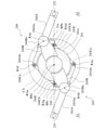
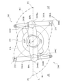
図4は、図3の搬送装置20における基点及び接続部の位置関係の一例を示す平面図である。これに限定されないが、本実施の形態では、図4に示すように、第1リンク構造体243において、第3接続部243Baと第1基点BPaとの距離である第2リンク距離LL2は、第1基点BPaと第2基点BPbとの距離である第1基点距離LB1よりも大きい。例えば、第2リンク距離LL2は、第3接続部243Baの軸RAbと第1基点BPaとの距離である。第1基点BPaを中心に第2リンク243Bが回動する場合、第3接続部243Baは、第1基点BPaを中心として第2基点BPbの水平方向外側を通る円周CA上を移動する。
さらに、第4接続部243Caと第2基点BPbとの距離である第3リンク距離LL3は、第1接続部243Aaと第2接続部243Abとの距離である第1リンク距離LL1よりも大きい。例えば、第1リンク距離LL1は、第1接続部243Aaの軸RAbと第2接続部243Abの軸RAcとの距離である。例えば、第3リンク距離LL3は、第4接続部243Caの軸RAcと第2基点BPbとの距離である。第1基点BPaを中心に第2リンク243Bが回転方向DRAに回動する場合、第1リンク243Aは、第3リンク243Cに対して軸RAcを中心とする回転方向DRAで正の角度を有する状態を維持する。つまり、平面視で、第1リンク243Aは第3リンク243Cと重ならず且つ交差しない状態を維持する。図4において、回転方向DRAは反時計回りの方向であり、回転方向DRBは時計回りの方向である。平面視は、上方から下方に向かって視ることであり、図4の状態を示す。
同様に、第2リンク構造体244において、第7接続部244Baと第1基点BPaとの距離である第5リンク距離LL5は、第1基点BPaと第3基点BPcとの距離である第2基点距離LB2よりも大きい。例えば、第5リンク距離LL5は、第7接続部244Baの軸RAeと第1基点BPaとの距離である。第1基点BPaを中心に第5リンク244Bが回動する場合、第7接続部244Baは、第1基点BPaを中心として第3基点BPcの水平方向外側を通る円周CA上を移動する。
さらに、第8接続部244Caと第3基点BPcとの距離である第6リンク距離LL6は、第5接続部244Aaと第6接続部244Abとの距離である第4リンク距離LL4よりも大きい。例えば、第4リンク距離LL4は、第5接続部244Aaの軸RAeと第6接続部244Abの軸RAfとの距離である。例えば、第6リンク距離LL6は、第8接続部244Caの軸RAfと第3基点BPcとの距離である。第1基点BPaを中心に第5リンク244Bが回転方向DRAに回動する場合、第4リンク244Aは、第6リンク244Cに対して軸RAfを中心とする回転方向DRAで正の角度を有する状態を維持し、平面視で第6リンク244Cと重ならず且つ交差しない状態を維持する。
また、図4に示す状態では、第1保持部231は、搭載領域A1の搭載点P1に位置し、第2保持部232は、処理領域A2の処理点P2に位置する。これに限定されないが、本実施の形態では、処理点P2は、第1基点BPaに関して搭載点P1と点対称な位置にある。第1リンク構造体243及び第2リンク構造体244はそれぞれ、第1保持部231及び第2保持部232を、搭載点P1と処理点P2との間で移動させるように構成される。搭載点P1は、第1地点及び第4地点の一例であり、処理点P2は、第2地点及び第3地点の一例である。
このような第1リンク構造体243及び第2リンク構造体244において、第1保持部231が搭載点P1に位置し且つ第2保持部232が処理点P2に位置するとき、第2基点BPbは、第2接続部243Ab及び第6接続部244Abから第1距離に位置し、第3基点BPcは、第1基点BPaに関して第2基点BPbと反対側で、第2接続部243Ab及び第6接続部244Abから第1距離に位置する。これにより、第1リンク243A、第2リンク243B及び第3リンク243Cは、第4リンク244A、第5リンク244B及び第6リンク244Cと、第1基点BPaに関して点対称な配置関係にある。さらに、第1基点BPaは、第2接続部243Ab及び第6接続部244Abから第2距離に位置する。上記状態での第2接続部243Abの位置及び第6接続部244Abの位置はそれぞれ、第1接続部位置及び第3接続部位置の一例である。
自転機構250の構成を説明する。図2に示すように、自転機構250は、第1保持部231及び第2保持部232に選択的に駆動力を付与する第2駆動装置251と、第2駆動装置251の駆動力を第1保持部231に伝達する第1伝達部252Aと、第2駆動装置251の駆動力を第2保持部232に伝達する第2伝達部252Bとを備える。第1伝達部252Aは第1リンク243A内に配置され、第2伝達部252Bは第4リンク244A内に配置される。第1伝達部252Aと第2伝達部252Bとは同様の構成を有するため、以下において、第2駆動装置251及び第2伝達部252Bの構成を中心に説明し、第1伝達部252Aの構成の説明を省略する。
図5は、例示的な実施の形態に係る搬送装置20の自転機構250の構成の一例を示す側面図であり、第4リンク244Aの断面側面図を示す。図5は、第2駆動装置251及び第2伝達部252Bの構成の一例を示す。図2及び図5に示すように、第2駆動装置251は、自転用モータ251aと、歯車251bと、モータ支持体251cと、スライド駆動装置251dと、第2支持体251eとを含む。
自転用モータ251aは、歯車251bを回転駆動するように構成される。本実施の形態では、自転用モータ251aは、サーボモータである。自転用モータ251aは、その回転量を検出するエンコーダ等の回転センサと、その電流値を検出する電流センサ又は回路とを備え、回転量及び電流値の検出信号を出力することができる。
モータ支持体251cは、自転用モータ251aを支持し、基部21に対して水平方向D1及びD2に移動可能であるように構成される。方向D1は基部21から離れる方向であり、方向D2は、方向D1と反対であり且つ基部21に接近する方向である。モータ支持体251cは、方向D1に向いた当接部251caと、側方に突出する係合部251cbとを含む。
スライド駆動装置251dは、モータ支持体251cの係合部251cbと係合する係合部251daと、係合部251daを方向D1及びD2にスライド移動させるアクチュエータ251dbとを含む。アクチュエータ251dbの動力は、電力であってもよく、空気圧又は液圧等の電力以外の動力であってもよい。アクチュエータ251dbは、係合部251daをスライド移動させることにより、モータ支持体251c及び自転用モータ251aを方向D1及びD2にスライド移動させることができる。
第2支持体251eは、モータ支持体251c及びスライド駆動装置251dを支持する。第2支持体251eは、基部21に固定されている。第2支持体251eは、基部21に対して方向D1及びD2にスライド可能であるように、モータ支持体251cを支持する。第2支持体251eは、基部21に対して位置を不動にスライド駆動装置251dを支持する。
第2伝達部252Bは、第1伝達軸2521と、第2伝達軸2522と、第3伝達軸2523と、伝達ベルト2524と、係止機構2525とを含む。これに限定されないが、本実施の形態では、伝達軸2521、2522及び2523はいずれも、上下方向に延びる。第1伝達軸2521は第2保持部232の近傍に配置され、第3伝達軸2523は第5接続部244Aaの近傍に配置され、第2伝達軸2522は、第1伝達軸2521と第3伝達軸2523との間に配置される。
第1伝達軸2521の一端は、第4リンク244Aの外部に上方へ延び、第2保持部232と一体に回転するように接続される。第2保持部232は、第1伝達軸2521によって下方から支持される。第1伝達軸2521の他端は、第4リンク244Aの輪郭を形成する底壁244Acによって回転可能に支持される。第1伝達軸2521は、他端の近傍に、一体に回転する歯車2521aを有する。
第2伝達軸2522の一端及び他端はそれぞれ、第4リンク244Aの輪郭を形成する上壁244Ad及び底壁244Acによって回転可能に支持される。第2伝達軸2522は、一端の近傍に一体に回転するプーリ2522aを有し、他端の近傍に一体に回転する歯車2522bを有する。歯車2522bの外周面のギヤ歯は、歯車2521aの外周面のギヤ歯とギヤ係合している。
第3伝達軸2523の一端は上壁244Adによって回転可能に支持され、第3伝達軸2523の他端は、第4リンク244Aの外部に下方へ延びる。第3伝達軸2523は、一端の近傍に一体に回転するプーリ2523aを有し、他端の近傍且つ第4リンク244Aの外部に一体に回転する歯車2523bを有する。歯車2523bの周面のギヤ歯は、歯車251bの周面のギヤ歯とギヤ係合可能である。
伝達ベルト2524は、無端輪状のベルトであり、互いに回転駆動力を伝達可能にプーリ2522a及び2523aにかけ渡される。
係止機構2525は、第3伝達軸2523の歯車2523bの回転の係止及び係止解除を行うことができるように構成される。係止機構2525は、歯車2523bに形成された軸方向の孔2523cの内周面に係合可能な係止体2525aと、係止体2525aを孔2523cの内周面に向かう方向D2へ付勢する付勢部材2525bとを含む。本実施の形態では、付勢部材2525bはコイルバネであるが、いかなる構成であってもよい。
上述のような自転機構250において、スライド駆動装置251dが自転用モータ251aを方向D2に移動させているとき、自転用モータ251aの歯車251bは、第2伝達部252Bの歯車2523bと係合しない。係止機構2525は、係止体2525aを孔2523cに係合させ、歯車2523bを回転しないように係止する。これにより、伝達軸2521、2522及び2523が回転しないように係止されるため、第2保持部232は第1伝達軸2521の回転方向で固定される。
スライド駆動装置251dが自転用モータ251aを方向D1に移動させると、モータ支持体251cの当接部251caが係止体2525aを方向D1に押圧して移動させ、係止体2525aと孔2523cとの係合を解除する。さらに、自転用モータ251aの歯車251bが第2伝達部252Bの歯車2523bとギヤ係合する。この状態で自転用モータ251aが駆動すると、自転用モータ251aの回転駆動力は、第3伝達軸2523、第2伝達軸2522及び第1伝達軸2521に順次伝達され、第2保持部232を回転させる。第2保持部232によって保持される対象物Wは、第1伝達軸2521の軸回りに回転される。自転用モータ251aの回転方向に応じて、第2保持部232の回転方向が変更され得る。
図2及び図5は、第2保持部232が処理点P2に位置する状態を示す。この状態では、第2駆動装置251は、第2伝達部252Bを駆動することができ、それにより、第2保持部232を回転駆動することができる。また、搬送装置20が動作することで第1保持部231が処理点P2に位置するとき、第2駆動装置251は、第2伝達部252Bと同様に、第1伝達部252Aを駆動することができ、それにより、第1保持部231を回転駆動することができる。第2駆動装置251は、第1保持部231と第2保持部232とを選択的に回転駆動することができる。
[搬送装置の動作]
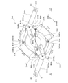
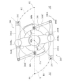
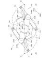
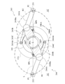
例示的な実施の形態に係る搬送装置20の動作の一例を説明する。具体的には、第1リンク構造体243及び第2リンク構造体244の動作を説明する。図6は、図4の搬送装置20において保持部231及び232を45度回動させた状態の一例を示す平面図である。図7は、図4の搬送装置20において保持部231及び232を90度回動させた状態の一例を示す平面図である。図8は、図4の搬送装置20において保持部231及び232を135度回動させた状態の一例を示す平面図である。図9は、図4の搬送装置20において保持部231及び232を180度回動させた状態の一例を示す平面図である。
例示的な実施の形態に係る搬送装置20の動作の一例を説明する。具体的には、第1リンク構造体243及び第2リンク構造体244の動作を説明する。図6は、図4の搬送装置20において保持部231及び232を45度回動させた状態の一例を示す平面図である。図7は、図4の搬送装置20において保持部231及び232を90度回動させた状態の一例を示す平面図である。図8は、図4の搬送装置20において保持部231及び232を135度回動させた状態の一例を示す平面図である。図9は、図4の搬送装置20において保持部231及び232を180度回動させた状態の一例を示す平面図である。
まず、図4に示すように、第1保持部231が搭載点P1に位置し且つ第2保持部232が処理点P2に位置する状態において、第1駆動装置242が駆動され、回転体241を方向DRAに回転させる。これにより、図6に示すように、第3接続部243Ba及び第7接続部244Baが円周CA上を方向DRAへ移動し、第1リンク243A及び第3リンク243Cが内角を減少させて屈折するように動作し、第4リンク244A及び第6リンク244Cが内角を減少させて屈折するように動作する。保持部231及び232はそれぞれ、円周CAに次第に近づく弧状形状の経路R1及びR2上を移動する。
図6の状態から回転体241がさらに回転されると、図7に示すように、第1リンク243A及び第3リンク243Cが内角を減少させ且つ第4リンク244A及び第6リンク244Cが内角を減少させつつ、保持部231及び232はそれぞれ、円周CAの内側に向かう経路R1及びR2上を移動する。図6と図7との間では、経路R1及びR2は、変曲点を含む曲線を描く。
図7の状態から回転体241がさらに回転されると、図8に示すように、第1リンク243A及び第3リンク243Cが内角を減少させ且つ第4リンク244A及び第6リンク244Cが内角を減少させつつ、保持部231及び232はそれぞれ、円周CAの外側に向かう経路R1及びR2上を移動する。図7と図8との間では、経路R1及びR2は、変曲点を含み且つ円周CAの外側では円周CAから次第に離れる曲線を描く。
図8の状態から回転体241がさらに回転されると、図9に示すように、第1リンク243A及び第3リンク243Cが内角を増加させ且つ第4リンク244A及び第6リンク244Cが内角を増加させつつ、保持部231及び232はそれぞれ、円周CAから次第に離れる弧状形状の経路R1及びR2上を移動する。図9では、第1保持部231は処理点P2に位置し、第2保持部232は搭載点P1に位置する。
よって、第1駆動装置242が回転体241を方向DRAに回転させることによって、第1リンク構造体243及び第2リンク構造体244は同期して動作し、第1リンク構造体243は、第1保持部231を搭載点P1から処理点P2に経路R1に沿って移動させ、第2リンク構造体244は、第2保持部232を処理点P2から搭載点P1に経路R2に沿って移動させる。図4の状態から図9の状態に至る過程で、回転体241は、方向DRAに180度回転する。
図9の状態において、第1リンク構造体243の第2接続部243Abは、第1基点BPaから第2距離に位置し、図4の状態での第2接続部243Abに対して第1基点BPaに関して点対称に位置する。第1基点BPaと第2基点BPbとを結ぶラインは、図9の状態での第2接続部243Abと図4の状態での第2接続部243Abとを結ぶ線分の垂直二等分線となる。図9の状態での第1リンク243Aと図4の状態での第1リンク243Aとは、第1基点BPaに関して点対称である。図9の状態での第2接続部243Abの位置は、第2接続部位置の一例である。
図9の状態において、第2リンク構造体244の第6接続部244Abは、第1基点BPaから第2距離に位置し、図4の状態での第6接続部244Abに対して第1基点BPaに関して点対称に位置する。第1基点BPaと第3基点BPcとを結ぶラインは、図9の状態での第6接続部244Abと図4の状態での第6接続部244Abとを結ぶ線分の垂直二等分線となる。図9の状態での第4リンク244Aと図4の状態での第4リンク244Aとは、第1基点BPaに関して点対称である。図9の状態での第6接続部244Abの位置は、第4接続部位置の一例である。
図9の状態において、第1駆動装置242が回転体241を方向DRBに回転させることによって、第1リンク構造体243及び第2リンク構造体244は同期して動作し、第1リンク構造体243は、第1保持部231を処理点P2から搭載点P1に経路R1に沿って移動し、第2リンク構造体244は、第2保持部232を搭載点P1から処理点P2に経路R2に沿って移動する。
経路R1及びR2は、搭載点P1と処理点P2とを結ぶラインLに垂直な方向への広がりを抑えた経路である。例えば、保持部231及び232が搭載点P1及び処理点P2から方向DRAに135度の角度まで回動する過程において、第1リンク243A及び第3リンク243Cが内角を減少させ且つ第4リンク244A及び第6リンク244Cが内角を減少させるため、経路R1及びR2はラインLに垂直な方向への広がりを抑えることができる。
保持部231及び232が搭載点P1と処理点P2との間を移動する過程において、第1リンク243A及び第3リンク243Cは、互いに交差も重なりもせず、第4リンク244A及び第6リンク244Cは、互いに交差も重なりもしない。これにより、第1リンク243A及び第4リンク244Aが回転体241に過度に接近し干渉することが防がれる。
[搬送装置の制御系統]
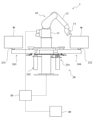
例示的な実施の形態に係る搬送装置20の制御系統を説明する。図10は、例示的な実施の形態に係るロボットシステム1の制御系統の構成の一例を示す側面図である。図11は、例示的な実施の形態に係るロボットコントローラ30のハードウェア構成の一例を示すブロック図である。図10に示すように、ロボットシステム1は、ロボットコントローラ30と、操作入力装置40とをさらに備える。ロボット10は、エンドエフェクタ13を備える。図10の例では、ロボットシステム1は、対象物Wへの塗装作業を行うように構成される。エンドエフェクタ13は塗装ガンである。搬送装置20は、未塗装の対象物Wの搭載領域A1から処理領域A2への移動及び塗装済みの対象物Wの処理領域A2から搭載領域A1への移動を、第1リンク構造体243及び第2リンク構造体244に交互に実行させる。
例示的な実施の形態に係る搬送装置20の制御系統を説明する。図10は、例示的な実施の形態に係るロボットシステム1の制御系統の構成の一例を示す側面図である。図11は、例示的な実施の形態に係るロボットコントローラ30のハードウェア構成の一例を示すブロック図である。図10に示すように、ロボットシステム1は、ロボットコントローラ30と、操作入力装置40とをさらに備える。ロボット10は、エンドエフェクタ13を備える。図10の例では、ロボットシステム1は、対象物Wへの塗装作業を行うように構成される。エンドエフェクタ13は塗装ガンである。搬送装置20は、未塗装の対象物Wの搭載領域A1から処理領域A2への移動及び塗装済みの対象物Wの処理領域A2から搭載領域A1への移動を、第1リンク構造体243及び第2リンク構造体244に交互に実行させる。
操作入力装置40は、種々の指令、情報及びデータ等の入力を受け付け、ロボットコントローラ30に出力する。例えば、操作入力装置40は、ロボットシステム1のユーザPによる入力を受け付けることができる。例えば、操作入力装置40は、レバー、ボタン、タッチパネル、ジョイスティック、モーションキャプチャ、カメラ及びマイク等の既知の入力手段を備えてもよい。例えば、操作入力装置40は、教示装置の1つであるティーチングペンダント、スマートフォン及びタブレットなどのスマートデバイス、パーソナルコンピュータ、並びに専用端末装置等の端末装置を備えてもよい。例えば、ロボット10がマスター・スレーブ方式で制御される場合、操作入力装置40はマスター機を備えてもよい。例えば、マスター機は、ロボットアーム12と同様又は類似する動作を行うことができるように構成されてもよい。
ロボットコントローラ30は、ロボット10の動作を制御する。これに限定されないが、本実施の形態では、ロボットコントローラ30は、搬送装置20の動作も制御する。ロボットコントローラ30は、操作入力装置40を介して入力される指令、情報及びデータ等を処理し、当該指令、情報及びデータ等に従ってロボット10及び搬送装置20の動作を制御する。ロボットコントローラ30は、コンピュータを備える。さらに、ロボットコントローラ30は、ロボット10及び搬送装置20に供給する電力を制御するための電気回路、ロボット10及び搬送装置20に供給する空気圧及び液圧等の電力以外の動力を制御するための機器、並びに、ロボット10に供給する塗料等の物質を制御するための機器等を備えてもよい。
例えば、ロボットコントローラ30のコンピュータは、処理回路又は回路を含む。回路は処理回路を含んでもよい。処理回路又は回路は、プロセッサ及び記憶装置等を含む。処理回路又は回路は、他の装置との指令、情報及びデータ等の送受信を行う。処理回路又は回路は、各種機器からの信号の入力及び各制御対象への制御信号の出力を行う。記憶装置は、メモリ、ストレージ、又は、メモリ及びストレージの両方を含んでもよい。メモリの例は、揮発性の半導体メモリであるRAM(Random Access Memory)及び不揮発性の半導体メモリであるROM(Read-Only Memory)等である。ストレージの例は、フラッシュメモリ等の半導体メモリ、ハードディスク及びSSD(Solid State Drive)等である。例えば、記憶装置は、処理回路又は回路が実行するプログラム、及び種々のデータ等を記憶する。
ロボットコントローラ30の複数の機能の少なくとも一部の機能は、プロセッサ、メモリ及びストレージ等の協働により実現されてもよい。プロセッサと、RAM及びROMを含むメモリとは、コンピュータシステムを構成する。例えば、コンピュータシステムは、プロセッサがRAMをワークエリアとして用いてROMに記録されたプログラムを実行することによって、上記機能を実現してもよい。なお、ロボットコントローラ30の機能の一部又は全部は、上記コンピュータシステムにより実現されてもよく、電子回路又は集積回路等の専用のハードウェア回路により実現されてもよく、上記コンピュータシステム及びハードウェア回路の組み合わせにより実現されてもよい。ロボットコントローラ30は、単一のコンピュータによる集中制御により処理を実行してもよく、複数のコンピュータの協働による分散制御により処理を実行してもよい。
ロボットコントローラ30は、ロボット10、搬送装置20及び操作入力装置40と、有線通信又は無線通信を介して接続される。これらの間の通信は、いかなる有線通信及び無線通信であってもよい。
図11を参照して、ロボットコントローラ30のハードウェア構成の一例を説明する。ロボットコントローラ30は、プロセッサの一例としてのCPU(Central Processing Unit)301と、メモリの一例としてのROM302及びRAM303と、メモリI/F(インタフェース:Interface)304と、入出力I/F305と、駆動I/F306とを含む。これらは、バス30Aによって互いに接続される。ロボットコントローラ30は、メモリI/F304に接続された記憶装置307と、入出力I/F305に接続された操作盤308と、駆動I/F306に接続された駆動回路309及び310とをさらに含む。本実施の形態では、ロボットコントローラ30は、コンピュータシステム及びハードウェア回路の組み合わせにより実現される。
メモリI/F304は、記憶装置307に対するデータの読み出し又は書き込み(記憶)を制御する。記憶装置307は、ロボットコントローラ30に内蔵される記憶装置であってもよく、外部の記憶装置であってもよい。後者の場合、記憶装置307は、フラシュメモリ、CD-ROM、CD-R及びDVD等の記憶媒体、並びに、ハードディスク及びSSD等の記憶装置であってもよい。
入出力I/F305は、操作盤308等と信号等の通信をするためのインタフェースである。操作盤308は、ロボットコントローラ30に備え付けられた操作盤である。操作盤308は、操作入力装置40と接続され、操作入力装置40と信号の送受信を行う。
駆動I/F306は、駆動回路309及び310と信号等の通信をするためのインタフェースである。第1駆動回路309は、ロボットアーム12の各関節を駆動する駆動装置に供給する電力を制御する。例えば、当該駆動装置は、駆動力を発生する電気モータとしてサーボモータを含む。CPU301及び第1駆動回路309は、ロボットアーム12をサーボ制御する。第2駆動回路310は、エンドエフェクタ13を駆動する電気モータ、並びに搬送装置20の駆動装置242及び251等に供給する電力を制御する。CPU301及び第2駆動回路310は、駆動装置242及び251をサーボ制御し、各サーボモータに含まれる回転センサ及び電流センサ等からの検出信号をフィードバック情報として用いて制御を行う。
CPU301は、ロボットアーム12の関節のモータの駆動軸の動作と、エンドエフェクタ13並びに駆動装置242及び251のモータの駆動軸の動作とを一括して制御する。例えば、CPU301は、ロボットアーム12の関節のモータの駆動軸と、エンドエフェクタ13並びに駆動装置242及び251のモータの駆動軸とを同期して動作させるように制御することができる。CPU301は、エンドエフェクタ13並びに駆動装置242及び251のモータの駆動軸の動作を、ロボットアーム12の関節のモータの駆動軸の動作制御の外部軸制御として、制御することができる。
(その他の実施の形態)
以上、本開示の例示的な実施の形態について説明したが、本開示は、上記実施の形態に限定されない。すなわち、本開示の範囲内で種々の変形及び改良が可能である。例えば、各種変形を実施の形態に施したもの、及び、異なる実施の形態における構成要素を組み合わせて構築される形態も、本開示の範囲内に含まれる。
以上、本開示の例示的な実施の形態について説明したが、本開示は、上記実施の形態に限定されない。すなわち、本開示の範囲内で種々の変形及び改良が可能である。例えば、各種変形を実施の形態に施したもの、及び、異なる実施の形態における構成要素を組み合わせて構築される形態も、本開示の範囲内に含まれる。
例えば、例示的な実施の形態に係る搬送装置20では、第1駆動装置242は、回転体241を回転させることで、第2リンク243B及び第5リンク244Bを一緒に回動するように構成されるが、これに限定されない。例えば、第1駆動装置242は、第1リンク構造体243の接続部の少なくとも1つ、第2リンク構造体244の接続部の少なくとも1つ、又は、第1リンク構造体243の接続部の少なくとも1つ及び第2リンク構造体244の接続部の少なくとも1つを回転駆動するように構成されてもよい。上記接続部を回転駆動することによって、第1リンク構造体243及び第2リンク構造体244の両方を動作させることができる。
例示的な実施の形態に係る搬送装置20では、第2リンク243B及び第5リンク244Bが一体化されるが、これに限定されず、分離されてもよい。例えば、第1駆動装置242は第1リンク構造体243及び第2リンク構造体244それぞれに設けられてもよい。
例示的な実施の形態に係る搬送装置20では、第2リンク243Bの第3接続部243Ba及び第5リンク244Bの第7接続部244Baは、同一の円周CA上を回動するように構成されるが、これに限定されず、異なる円周上を回動するように構成されてもよい。
例示的な実施の形態に係る搬送装置20では、第2駆動装置251は、第1保持部231及び第2保持部232を選択的に駆動するように構成されるが、これに限定されない。例えば、第2駆動装置251は第1保持部231及び第2保持部232それぞれに設けられてもよい。
例示的な実施の形態に係る搬送装置20は、2つのリンク構造体243及び244を備えるように構成されるが、これに限定されない。例えば、搬送装置20は、1つ又は3つ以上のリンク構造体を備えてもよい。例えば、3つ以上のリンク構造体は、リンク構造体243及び244のように少なくとも1つのリンクで一体化され、互いに同期して動作するように構成されてもよい。
例示的な実施の形態に係る搬送装置20において、搭載点P1が第1地点及び第4地点であり、処理点P2が第2地点及び第3地点であるが、これに限定されない。例えば、第1地点及び第4地点は異なる位置に配置されてもよく、第2地点及び第3地点は異なる位置に配置されてもよい。第1地点及び第2地点は第1基点BPaに関して点対称な関係でなくてもよく、第3地点及び第4地点は第1基点BPaに関して点対称な関係でなくてもよい。
また、本開示の技術の各態様例は、以下のように挙げられる。本開示の一態様に係る搬送装置は、対象物を保持し搬送する搬送装置であって、第1接続部と、前記第1接続部から離れた位置にある第2接続部と、前記第1接続部に関して前記第2接続部と反対側にある対象物の第1保持部とを有する第1リンクと、前記第1接続部と回動可能に接続される第3接続部を有し、第1基点を中心に前記第3接続部を回動するように動作可能である第2リンクと、前記第2接続部と回動可能に接続される第4接続部を有し、前記第1基点から離れた位置にある第2基点を中心に前記第4接続部を回動するように動作可能である第3リンクと、前記第1リンクから前記第3リンクを動作させる第1駆動装置とを備え、前記第1リンクから前記第3リンクは、前記第1基点に関して互いに反対側にある第1地点及び第2地点の間で、前記第2リンクの動作に伴って前記第1保持部を前記第1基点に接近させつつ移動するように構成される。
上記態様によると、搬送装置は、第1保持部を第1基点に接近させつつ第1地点と第2地点との間で移動させることができる。よって、搬送装置は、対象物の搬送のための占有面積の低減を可能にする。さらに、搬送装置は、互いに接続された3つのリンクを用いて第1保持部を移動可能に支持する。例えば、3つのリンクうちの1つのリンクが駆動力を受けて動作すると、他の2つのリンクも連動して動作し、それにより、3つのリンクが第1保持部を移動させることができる。このため、第1駆動装置は、3つのリンクのうちの少なくとも1つを動作できるように構成され得る。よって、搬送装置は、第1保持部を移動させるための構造を簡略化することを可能にする。
本開示の一態様に係る搬送装置において、1つの前記第1駆動装置が、前記第1接続部から前記第4接続部、前記第1基点及び前記第2基点のうちの1つにおいて、前記第1リンクから前記第3リンクの1つ以上を駆動するように配置されてもよい。上記態様によると、搬送装置は、1つの第1駆動装置を用いて3つのリンクを動作させる。よって、搬送装置は、第1保持部を移動させるための構造を簡略化することを可能にする。
本開示の一態様に係る搬送装置において、前記第3接続部と前記第1基点との距離である第2リンク距離は、前記第1基点と前記第2基点との距離である第1基点距離よりも大きくてもよい。上記態様によると、第1地点と第2地点との間の搬送時、第1基点を中心とする第1接続部及び第3接続部の回動方向と、第1接続部及び第3接続部を中心とする第1保持部の回動方向とが、同じになり得る。例えば、第1接続部及び第3接続部が第1基点を中心に第1方向に180度回動すると、第1保持部は、第1接続部及び第3接続部を中心に第1方向に180度回動し得る。よって、搬送装置は、第1保持部を第1基点に関する回転対称の位置に移動することができる。
本開示の一態様に係る搬送装置において、前記第4接続部と前記第2基点との距離である第3リンク距離は、前記第1接続部と前記第2接続部との距離である第1リンク距離よりも大きくてもよい。上記態様によると、第1地点と第2地点との間の搬送時、第1リンクにおける第1接続部と第2接続部との間の部分と、第3リンクとがなす角度を小さくするような構成が可能である。例えば、第1接続部が第2基点に接近することが可能である。よって、第1地点と第2地点との間の搬送時、搬送装置は、第1保持部を第1基点に接近させるように動作することができる。
本開示の一態様に係る搬送装置において、前記第1地点及び前記第2地点は、前記第1基点に関して互いに対称に位置し、前記第2接続部の特定の位置である第1接続部位置及び第2接続部位置は、前記第1基点に関して互いに対称に位置し、前記第1接続部位置は、前記第1保持部が前記第1地点に位置するときの前記第2接続部の位置であり、前記第2接続部位置は、前記第1保持部が前記第2地点に位置するときの前記第2接続部の位置であってもよい。上記態様によると、第1接続部位置に位置する第1リンクと第2接続部位置に位置する第1リンクとは、第1基点に関して対称な関係になり得る。これにより、搬送装置は、第2リンクに第3接続部を180度回動させることで、第1地点から第2地点にわたる点対称な2つの位置の間で第1保持部を移動させることができる。
本開示の一態様に係る搬送装置において、前記第1保持部は、前記第1リンクに対して回動可能であり、前記搬送装置は、前記第1保持部を駆動する第2駆動装置をさらに備えてもよい。上記態様によると、搬送装置は、第1保持部を回動させることで、第1保持部によって保持されている対象物の向きを変えることができる。
本開示の一態様に係る搬送装置は、第5接続部と、前記第5接続部から離れた位置にある第6接続部と、前記第5接続部に関して前記第6接続部と反対側にある対象物の第2保持部とを有する第4リンクと、前記第5接続部と回動可能に接続される第7接続部を有し、前記第1基点を中心に前記第7接続部を回動するように動作可能である第5リンクと、前記第6接続部と回動可能に接続される第8接続部を有し、前記第1基点及び前記第2基点から離れた位置にある第3基点を中心に前記第8接続部を回動するように動作可能である第6リンクとを備え、前記第5リンクは、前記第1基点を中心に前記第2リンクと一体に回動するように前記第2リンクと一体化され、前記第4リンクから前記第6リンクは、前記第1基点に関して互いに反対側にある第3地点及び第4地点の間で、前記第5リンクの動作に伴って前記第2保持部を前記第1基点に接近させつつ移動するように構成されてもよい。
上記態様によると、搬送装置は、第1駆動装置を用いて第1リンクから第3リンクを動作させることによって、第2リンクと一体化された第5リンクを介して第4リンクから第6リンクを動作させることができる。よって、搬送装置は、簡略な構造により、第1保持部及び第2保持部を同時に移動させることができる。
本開示の一態様に係る搬送装置において、前記第1駆動装置は、前記第2リンク及び前記第5リンクを前記第1基点を中心に回転駆動するように配置されてもよい。上記態様によると、搬送装置は、1つの第1搬送装置を用いて第1保持部及び第2保持部を移動させることができる。さらに、第1搬送装置は、第1基点において第2リンク及び第5リンクを駆動するため、第1リンクから第3リンクと、第4リンクから第6リンクとに均等に回転駆動力を付与することができる。
本開示の一態様に係る搬送装置において、前記第7接続部と前記第1基点との距離である第5リンク距離は、前記第1基点と前記第3基点との距離である第2基点距離よりも大きくてもよい。上記態様によると、第3地点と第4地点との間の搬送時、第1基点を中心とする第5接続部及び第7接続部の回動方向と、第5接続部及び第7接続部を中心とする第2保持部の回動方向とが、同じになり得る。例えば、第5接続部及び第7接続部が第1基点を中心に第1方向に180度回動すると、第2保持部は、第5接続部及び第7接続部を中心に第1方向に180度回動し得る。よって、搬送装置は、第2保持部を第1基点に関する回転対称の位置に移動することができる。
本開示の一態様に係る搬送装置において、前記第8接続部と前記第3基点との距離である第6リンク距離は、前記第5接続部と前記第6接続部との距離である第4リンク距離よりも大きくてもよい。上記態様によると、第3地点と第4地点との間の搬送時、第4リンクにおける第5接続部と第6接続部との間の部分と、第6リンクとがなす角度を小さくするような構成が可能である。例えば、第5接続部が第3基点に接近することが可能である。よって、第3地点と第4地点との間の搬送時、搬送装置は、第2保持部を第1基点に接近させるように動作することができる。
本開示の一態様に係る搬送装置において、前記第3地点及び前記第4地点は、前記第1基点に関して互いに対称に位置し、前記第6接続部の特定の位置である第3接続部位置及び第4接続部位置は、前記第1基点に関して互いに対称に位置し、前記第3接続部位置は、前記第2保持部が前記第3地点に位置するときの前記第6接続部の位置であり、前記第4接続部位置は、前記第2保持部が前記第4地点に位置するときの前記第6接続部の位置であってもよい。上記態様によると、第3接続部位置に位置する第4リンクと第4接続部位置に位置する第4リンクとは、第1基点に関して対称な関係にある。これにより、搬送装置は、第5リンクに第7接続部を180度回動させることで、第3地点から第4地点にわたる点対称な2つの位置の間で第2保持部を移動させることができる。
本開示の一態様に係る搬送装置において、前記第3基点は、前記第1基点に関して前記第2基点と反対側に位置してもよい。上記態様によると、第4リンクから第6リンクと第1リンクから第3リンクとの干渉を抑制することが可能になる。
本開示の一態様に係る搬送装置において、前記第4リンク、前記第5リンク及び前記第6リンクはそれぞれ、前記第1リンク、前記第2リンク及び前記第3リンクと同様の構成を有してもよい。上記態様によると、搬送装置は、第1保持部及び第2保持部に同様の経路に沿った移動をさせることができる。
本開示の一態様に係る搬送装置において、前記第1保持部が前記第1地点に位置し且つ前記第2保持部が前記第3地点に位置するとき、前記第2基点は、前記第2接続部及び前記第6接続部から第1距離に位置し、前記第3基点は、前記第1基点に関して前記第2基点と反対側で、前記第2接続部及び前記第6接続部から前記第1距離に位置し、前記第3地点は、前記第1基点に関して前記第1地点と反対側に位置してもよい。
上記態様によると、第2基点及び第3基点が第1基点に関して互いに反対側に配置され、第1地点及び第3地点が第1基点に関して互いに反対側に配置され、第2地点及び第4地点が第1基点に関して互いに反対側に配置され得る。さらに、第1保持部が第1地点に位置し且つ第2保持部が前記第3地点に位置するとき、第2接続部及び第6接続部はいずれも、第2基点及び第3基点から第1距離に位置する。これにより、第1リンクから第3リンクと第4リンクから第6リンクとは、第1基点に関して点対称な構成を有する。よって、第1地点及び第4地点が同様の位置に配置され、第2地点及び第3地点が同様の位置に配置されることが可能である。従って、搬送装置は、2つの地点間で第1保持部及び第2保持部を移動させることができる。
本開示の一態様に係る搬送装置は、前記第2保持部と前記第1保持部とを選択的に駆動するように構成される第2駆動装置をさらに備え、前記第1保持部は、前記第1リンクに対して回動可能であり、前記第2保持部は、前記第4リンクに対して回動可能であってもよい。上記態様によると、搬送装置は、1つの第2駆動装置により第1保持部及び第2保持部を選択的に駆動することができる。保持部を駆動するための制御系統の簡略化が可能になる。
本開示の一態様に係るロボットシステムは、本開示の一態様に係る搬送装置と、1つ以上の関節をもつアームを有し且つ前記搬送装置によって搬送される対象物を処理するロボットと、前記ロボットの動作を制御するロボットコントローラとを備える。上記態様によると、本開示の一態様に係る搬送装置と同様の効果が得られる。
本開示の一態様に係るロボットシステムにおいて、前記ロボットコントローラは、複数の駆動装置の駆動軸を同期して動作させるように前記複数の駆動装置を制御可能に構成され、前記複数の駆動装置の駆動軸は、前記アームの前記関節の駆動装置の駆動軸と、前記搬送装置の前記駆動装置の駆動軸とを含んでもよい。上記態様によると、ロボットコントローラの制御系統を利用した、ロボット及び搬送装置の制御が可能である。例えば、ロボットコントローラは、搬送装置の駆動装置を、外部軸として制御することが可能である。
本明細書で開示する要素の機能は、開示された機能を実行するよう構成又はプログラムされた汎用プロセッサ、専用プロセッサ、集積回路、ASIC(Application-Specific Integrated Circuit)、従来の回路、及び/又は、それらの組み合わせ、を含む回路又は処理回路を使用して実行できる。プロセッサは、トランジスタやその他の回路を含むため、処理回路又は回路と見なされる。本開示において、回路、ユニット、又は手段は、列挙された機能を実行するハードウェアであるか、又は、列挙された機能を実行するようにプログラムされたハードウェアである。ハードウェアは、本明細書に開示されているハードウェアであってもよいし、あるいは、列挙された機能を実行するようにプログラム又は構成されているその他の既知のハードウェアであってもよい。ハードウェアが回路の一種と考えられるプロセッサである場合、回路、手段、又はユニットはハードウェアとソフトウェアの組み合わせであり、ソフトウェアはハードウェア及び/又はプロセッサの構成に使用される。
上記で用いた序数、数量等の数字は、全て本開示の技術を具体的に説明するために例示するものであり、本開示は例示された数字に制限されない。また、構成要素間の接続関係は、本開示の技術を具体的に説明するために例示するものであり、本開示の機能を実現する接続関係はこれに限定されない。
1 ロボットシステム
10 ロボット
12 ロボットアーム
20 搬送装置
30 ロボットコントローラ
231 第1保持部
232 第2保持部
242 第1駆動装置
243A 第1リンク
243Aa 第1接続部
243Ab 第2接続部
243B 第2リンク
243Ba 第3接続部
243C 第3リンク
243Ca 第4接続部
244A 第4リンク
244Aa 第5接続部
244Ab 第6接続部
244B 第5リンク
244Ba 第7接続部
244C 第6リンク
244Ca 第8接続部
251 第2駆動装置
BPa 第1基点
BPb 第2基点
BPc 第3基点
LB1 第1基点距離
LB2 第2基点距離
LL1 第1リンク距離
LL2 第2リンク距離
LL3 第3リンク距離
LL4 第4リンク距離
LL5 第5リンク距離
LL6 第6リンク距離
P1 搭載点(第1地点、第4地点)
P2 処理点(第2地点、第3地点)
W 対象物
Claims (16)
- 対象物を保持し搬送する搬送装置であって、
第1接続部と、前記第1接続部から離れた位置にある第2接続部と、前記第1接続部に関して前記第2接続部と反対側にある対象物の第1保持部とを有する第1リンクと、
前記第1接続部と回動可能に接続される第3接続部を有し、第1基点を中心に前記第3接続部を回動するように動作可能である第2リンクと、
前記第2接続部と回動可能に接続される第4接続部を有し、前記第1基点から離れた位置にある第2基点を中心に前記第4接続部を回動するように動作可能である第3リンクと、
前記第1リンクから前記第3リンクを動作させる第1駆動装置とを備え、
前記第1リンクから前記第3リンクは、前記第1基点に関して互いに反対側にある第1地点及び第2地点の間で、前記第2リンクの動作に伴って前記第1保持部を前記第1基点に接近させつつ移動するように構成される、搬送装置。 - 1つの前記第1駆動装置が、前記第1接続部から前記第4接続部、前記第1基点及び前記第2基点のうちの1つにおいて、前記第1リンクから前記第3リンクの1つ以上を駆動するように配置される
請求項1に記載の搬送装置。 - 前記第3接続部と前記第1基点との距離である第2リンク距離は、前記第1基点と前記第2基点との距離である第1基点距離よりも大きい
請求項1又は2に記載の搬送装置。 - 前記第4接続部と前記第2基点との距離である第3リンク距離は、前記第1接続部と前記第2接続部との距離である第1リンク距離よりも大きい
請求項3に記載の搬送装置。 - 前記第1地点及び前記第2地点は、前記第1基点に関して互いに対称に位置し、
前記第2接続部の特定の位置である第1接続部位置及び第2接続部位置は、前記第1基点に関して互いに対称に位置し、
前記第1接続部位置は、前記第1保持部が前記第1地点に位置するときの前記第2接続部の位置であり、
前記第2接続部位置は、前記第1保持部が前記第2地点に位置するときの前記第2接続部の位置である
請求項1から4のいずれか一項に記載の搬送装置。 - 前記第1保持部は、前記第1リンクに対して回動可能であり、
前記搬送装置は、前記第1保持部を駆動する第2駆動装置をさらに備える
請求項1から5のいずれか一項に記載の搬送装置。 - 第5接続部と、前記第5接続部から離れた位置にある第6接続部と、前記第5接続部に関して前記第6接続部と反対側にある対象物の第2保持部とを有する第4リンクと、
前記第5接続部と回動可能に接続される第7接続部を有し、前記第1基点を中心に前記第7接続部を回動するように動作可能である第5リンクと、
前記第6接続部と回動可能に接続される第8接続部を有し、前記第1基点及び前記第2基点から離れた位置にある第3基点を中心に前記第8接続部を回動するように動作可能である第6リンクとを備え、
前記第5リンクは、前記第1基点を中心に前記第2リンクと一体に回動するように前記第2リンクと一体化され、
前記第4リンクから前記第6リンクは、前記第1基点に関して互いに反対側にある第3地点及び第4地点の間で、前記第5リンクの動作に伴って前記第2保持部を前記第1基点に接近させつつ移動するように構成される
請求項1から6のいずれか一項に記載の搬送装置。 - 前記第1駆動装置は、前記第2リンク及び前記第5リンクを前記第1基点を中心に回転駆動するように配置される
請求項7に記載の搬送装置。 - 前記第7接続部と前記第1基点との距離である第5リンク距離は、前記第1基点と前記第3基点との距離である第2基点距離よりも大きい
請求項7又は8に記載の搬送装置。 - 前記第8接続部と前記第3基点との距離である第6リンク距離は、前記第5接続部と前記第6接続部との距離である第4リンク距離よりも大きい
請求項9に記載の搬送装置。 - 前記第3地点及び前記第4地点は、前記第1基点に関して互いに対称に位置し、
前記第6接続部の特定の位置である第3接続部位置及び第4接続部位置は、前記第1基点に関して互いに対称に位置し、
前記第3接続部位置は、前記第2保持部が前記第3地点に位置するときの前記第6接続部の位置であり、
前記第4接続部位置は、前記第2保持部が前記第4地点に位置するときの前記第6接続部の位置である
請求項7から10のいずれか一項に記載の搬送装置。 - 前記第4リンク、前記第5リンク及び前記第6リンクはそれぞれ、前記第1リンク、前記第2リンク及び前記第3リンクと同様の構成を有する
請求項7から11のいずれか一項に記載の搬送装置。 - 前記第1保持部が前記第1地点に位置し且つ前記第2保持部が前記第3地点に位置するとき、前記第2基点は、前記第2接続部及び前記第6接続部から第1距離に位置し、前記第3基点は、前記第1基点に関して前記第2基点と反対側で、前記第2接続部及び前記第6接続部から前記第1距離に位置し、
前記第3地点は、前記第1基点に関して前記第1地点と反対側に位置する
請求項12に記載の搬送装置。 - 前記第2保持部と前記第1保持部とを選択的に駆動するように構成される第2駆動装置をさらに備え、
前記第1保持部は、前記第1リンクに対して回動可能であり、
前記第2保持部は、前記第4リンクに対して回動可能である
請求項7から13のいずれか一項に記載の搬送装置。 - 請求項1から14のいずれか一項に記載の搬送装置と、
1つ以上の関節をもつアームを有し且つ前記搬送装置によって搬送される対象物を処理するロボットと、
前記ロボットの動作を制御するロボットコントローラとを備える
ロボットシステム。 - 前記ロボットコントローラは、複数の駆動装置の駆動軸を同期して動作させるように前記複数の駆動装置を制御可能に構成され、
前記複数の駆動装置の駆動軸は、前記アームの前記関節の駆動装置の駆動軸と、前記搬送装置の前記駆動装置の駆動軸とを含む
請求項15に記載のロボットシステム。
Priority Applications (2)
| Application Number | Priority Date | Filing Date | Title |
|---|---|---|---|
| CN202180060742.1A CN116157239A (zh) | 2020-07-13 | 2021-07-06 | 运送装置以及机器人系统 |
| US18/016,044 US12338081B2 (en) | 2020-07-13 | 2021-07-06 | Conveying device and robot system |
Applications Claiming Priority (2)
| Application Number | Priority Date | Filing Date | Title |
|---|---|---|---|
| JP2020-119909 | 2020-07-13 | ||
| JP2020119909A JP7551366B2 (ja) | 2020-07-13 | 2020-07-13 | 搬送装置及びロボットシステム |
Publications (1)
| Publication Number | Publication Date |
|---|---|
| WO2022014409A1 true WO2022014409A1 (ja) | 2022-01-20 |
Family
ID=79555360
Family Applications (1)
| Application Number | Title | Priority Date | Filing Date |
|---|---|---|---|
| PCT/JP2021/025448 Ceased WO2022014409A1 (ja) | 2020-07-13 | 2021-07-06 | 搬送装置及びロボットシステム |
Country Status (4)
| Country | Link |
|---|---|
| US (1) | US12338081B2 (ja) |
| JP (1) | JP7551366B2 (ja) |
| CN (1) | CN116157239A (ja) |
| WO (1) | WO2022014409A1 (ja) |
Families Citing this family (2)
| Publication number | Priority date | Publication date | Assignee | Title |
|---|---|---|---|---|
| KR20240044158A (ko) * | 2022-09-28 | 2024-04-04 | 현대자동차주식회사 | 그리퍼 |
| CN119262776B (zh) * | 2024-11-13 | 2025-06-27 | 扬州骏毅电子有限责任公司 | 一种冰箱抽屉生产输送检测装置 |
Citations (3)
| Publication number | Priority date | Publication date | Assignee | Title |
|---|---|---|---|---|
| JPS63278739A (ja) * | 1987-05-07 | 1988-11-16 | Makita Denki Seisakusho:Kk | ロ−ダ−装置 |
| JPH072357A (ja) * | 1993-06-16 | 1995-01-06 | Kyoto Seisakusho:Kk | 物品の移載集積装置 |
| JP2012156308A (ja) * | 2011-01-26 | 2012-08-16 | Nabtesco Corp | ウエハ搬送ロボット |
Family Cites Families (10)
| Publication number | Priority date | Publication date | Assignee | Title |
|---|---|---|---|---|
| JPH1047444A (ja) * | 1996-08-08 | 1998-02-20 | Murata Mach Ltd | 動力伝達切換装置 |
| JP3884770B2 (ja) * | 1997-06-02 | 2007-02-21 | 有限会社装機設計 | 射出成形品取出装置 |
| JP3980490B2 (ja) * | 2003-01-15 | 2007-09-26 | 川崎重工業株式会社 | 搬送装置および加工設備 |
| JP5044138B2 (ja) * | 2006-04-17 | 2012-10-10 | 川崎重工業株式会社 | 搬送システムおよび加工設備 |
| JP4951028B2 (ja) * | 2009-05-28 | 2012-06-13 | 株式会社日本自動車部品総合研究所 | 車載アンテナ装置 |
| JP6386704B2 (ja) * | 2013-08-27 | 2018-09-05 | 川崎重工業株式会社 | ワーク搬送装置 |
| JP6528607B2 (ja) * | 2015-08-28 | 2019-06-12 | 株式会社ダイフク | 加工設備及び加工方法 |
| BR112019011459B1 (pt) * | 2016-12-06 | 2022-10-04 | Tmt-Tapping Measuring Technology Sàrl | Manipulador para girar em torno de seu próprio eixo um objeto de manipulação |
| JP2019000912A (ja) * | 2017-06-09 | 2019-01-10 | 川崎重工業株式会社 | ロボットアームの手首及び双腕ロボット |
| KR102528650B1 (ko) * | 2018-12-21 | 2023-05-03 | 호코스 가부시키가이샤 | 워크 반입출 장치 |
-
2020
- 2020-07-13 JP JP2020119909A patent/JP7551366B2/ja active Active
-
2021
- 2021-07-06 US US18/016,044 patent/US12338081B2/en active Active
- 2021-07-06 CN CN202180060742.1A patent/CN116157239A/zh active Pending
- 2021-07-06 WO PCT/JP2021/025448 patent/WO2022014409A1/ja not_active Ceased
Patent Citations (3)
| Publication number | Priority date | Publication date | Assignee | Title |
|---|---|---|---|---|
| JPS63278739A (ja) * | 1987-05-07 | 1988-11-16 | Makita Denki Seisakusho:Kk | ロ−ダ−装置 |
| JPH072357A (ja) * | 1993-06-16 | 1995-01-06 | Kyoto Seisakusho:Kk | 物品の移載集積装置 |
| JP2012156308A (ja) * | 2011-01-26 | 2012-08-16 | Nabtesco Corp | ウエハ搬送ロボット |
Also Published As
| Publication number | Publication date |
|---|---|
| US12338081B2 (en) | 2025-06-24 |
| US20230339704A1 (en) | 2023-10-26 |
| JP2022016916A (ja) | 2022-01-25 |
| JP7551366B2 (ja) | 2024-09-17 |
| CN116157239A (zh) | 2023-05-23 |
Similar Documents
| Publication | Publication Date | Title |
|---|---|---|
| US11978649B2 (en) | Substrate processing apparatus | |
| JP6336467B2 (ja) | 不等長の前腕部を備えた多軸ロボット装置、電子デバイス製造システム、及び、電子デバイス製造において基板を搬送するための方法 | |
| JP6051021B2 (ja) | 産業用ロボットおよび産業用ロボットの制御方法 | |
| US20050011294A1 (en) | Articulated robot | |
| TWI608912B (zh) | 雙臂真空機器人 | |
| JP2023033330A (ja) | 基板処理装置及び基板搬送装置 | |
| JP7407163B2 (ja) | 搬送システム、搬送方法および搬送装置 | |
| JP6252597B2 (ja) | ロボットシステム | |
| JP2016512398A (ja) | 基板堆積システム、ロボット移送装置、及び電子デバイス製造のための方法 | |
| KR102567510B1 (ko) | 종속화된 엔드 이펙터 움직임을 가진 로봇 | |
| JP2022016916A (ja) | 搬送装置及びロボットシステム | |
| TW201938340A (zh) | 疊排式線性軸機器人 | |
| JP2006013371A (ja) | 搬送装置及びその制御方法並びに真空処理装置 | |
| JP6892018B2 (ja) | ロボット装置 | |
| JP4515133B2 (ja) | 搬送装置及びその制御方法並びに真空処理装置 | |
| JP2020536761A5 (ja) | ||
| JP7005136B2 (ja) | 把持装置、ロボット装置、制御方法、制御プログラム、記録媒体、および物品の製造方法 | |
| JP5453590B2 (ja) | ロボットのハンドの制御方法及びワーク搬送ロボットシステム | |
| CN107234629B (zh) | 一种多轴机器人 | |
| JP5011507B2 (ja) | ロボット教示システム及びロボット教示方法 | |
| KR100471088B1 (ko) | 이송장치 | |
| JPWO2012070572A1 (ja) | ロボットの制御装置および制御方法 | |
| CN107901029A (zh) | 六轴并联机构及机器人 | |
| CN112775933B (zh) | 机器人系统、机器人的控制方法、半导体制造系统 | |
| JP7085736B2 (ja) | ロボットハンド |
Legal Events
| Date | Code | Title | Description |
|---|---|---|---|
| 121 | Ep: the epo has been informed by wipo that ep was designated in this application |
Ref document number: 21843368 Country of ref document: EP Kind code of ref document: A1 |
|
| NENP | Non-entry into the national phase |
Ref country code: DE |
|
| 122 | Ep: pct application non-entry in european phase |
Ref document number: 21843368 Country of ref document: EP Kind code of ref document: A1 |
|
| WWG | Wipo information: grant in national office |
Ref document number: 18016044 Country of ref document: US |