WO2022009688A1 - 金属空気電池および金属空気電池の製造方法 - Google Patents
金属空気電池および金属空気電池の製造方法 Download PDFInfo
- Publication number
- WO2022009688A1 WO2022009688A1 PCT/JP2021/023932 JP2021023932W WO2022009688A1 WO 2022009688 A1 WO2022009688 A1 WO 2022009688A1 JP 2021023932 W JP2021023932 W JP 2021023932W WO 2022009688 A1 WO2022009688 A1 WO 2022009688A1
- Authority
- WO
- WIPO (PCT)
- Prior art keywords
- metal
- water
- air battery
- film
- resin
- Prior art date
- Legal status (The legal status is an assumption and is not a legal conclusion. Google has not performed a legal analysis and makes no representation as to the accuracy of the status listed.)
- Ceased
Links
Images


Classifications
-
- H—ELECTRICITY
- H01—ELECTRIC ELEMENTS
- H01M—PROCESSES OR MEANS, e.g. BATTERIES, FOR THE DIRECT CONVERSION OF CHEMICAL ENERGY INTO ELECTRICAL ENERGY
- H01M12/00—Hybrid cells; Manufacture thereof
- H01M12/04—Hybrid cells; Manufacture thereof composed of a half-cell of the fuel-cell type and of a half-cell of the primary-cell type
- H01M12/06—Hybrid cells; Manufacture thereof composed of a half-cell of the fuel-cell type and of a half-cell of the primary-cell type with one metallic and one gaseous electrode
Definitions
- the present disclosure relates to a metal-air battery having a positive electrode and a negative electrode and a method for manufacturing the metal-air battery.
- Patent Document 1 As a metal-air battery of this type, for example, in Patent Document 1, a negative electrode, a separator, an air electrode, a water-repellent film, and an air diffusing paper are laminated, and an outer body of a polymer film having hydrogen gas permeability is combined with an electrolytic solution.
- the contained configuration is disclosed.
- the exterior body arranged on the air electrode side is provided with an air intake hole, and the air diffusion paper is fixed from the inside so as to cover the air intake hole.
- the water-repellent film is arranged inside the air diffusion paper for the purpose of supplying oxygen to the air electrode and preventing leakage of the electrolytic solution.
- the exterior body having an air intake hole and the air diffusing paper are adhered to each other, but the water repellent film and the air diffusing paper inside the outer body are not adhered to each other, and the water repellent film is also attached to the exterior body. Is not glued.
- the air-diffusing paper adhered to the exterior body diffuses air but does not have the ability to suppress liquid leakage. Therefore, in addition to the possibility of creating a gap between the exterior body and the water-repellent film, the electrolytic solution moves to the gap and reaches the air diffusion paper, and further, the electrolytic solution is passed through the air intake hole of the exterior body. Was in danger of leaking.
- the present disclosure has been made in view of the above-mentioned problems, and provides a metal-air battery capable of suppressing leakage of an electrolytic solution and suppressing a decrease in the water level of the electrolytic solution, and a method for manufacturing the same.
- the purpose is to be described in detail below.
- the first aspect of the present disclosure is a positive electrode, a negative electrode arranged to face the positive electrode, an electrolyte arranged at least between the positive electrode and the negative electrode, and the positive electrode.
- a metal air battery including an exterior body provided with an opening on the facing surface thereof and a water-repellent film covering the opening inside the exterior body, wherein the exterior body is made of a resin film and described above.
- the water-repellent film, the positive electrode, the negative electrode, and the electrolyte are housed inside the exterior body, and the water-repellent film is a porous film having a large number of pores.
- An adhesive interface of a polyolefin resin is provided between the two, and the water-repellent film is fixed to the exterior body.
- the exterior body and the water-repellent film are fixed at the peripheral edge of the opening via the adhesive interface.
- the opening of the exterior body is surely covered with the water-repellent film fixed to the exterior body via the adhesive interface, it is possible to prevent a gap from being formed between the exterior body and the water-repellent film. , It becomes possible to suppress the leakage of the electrolytic solution.
- the second aspect of the present disclosure comprises a positive electrode, a negative electrode arranged facing the positive electrode, and an electrolyte arranged at least between the positive electrode and the negative electrode.
- a method for manufacturing a metal air battery including an exterior body formed of a resin film and provided with an opening on a surface facing the positive electrode, and a water-repellent film covering the opening inside the exterior body.
- the water-repellent film is a porous film having a large number of pores, and a porous resin layer containing at least one type of polyolefin resin is provided on a surface facing the exterior body, and the water-repellent film is provided with the water-repellent film.
- a step of arranging the exterior body so as to face the opening and a step of welding the porous resin layer and the exterior body at least at the peripheral edge of the opening are included on the porous resin layer. It is characterized in that an adhesive interface between the exterior body and the water-repellent film is provided to fix the water-repellent film to the exterior body.
- the water-repellent film includes a porous resin layer, welding of the water-repellent film becomes easy, and it becomes possible to realize simplification of the manufacturing process and cost reduction.
- the present disclosure it is possible to obtain a metal-air battery capable of suppressing leakage of the electrolytic solution and suppressing a decrease in the water level of the electrolytic solution.
- FIG. 1 is a plan view showing a schematic configuration of a metal-air battery according to the first embodiment of the present disclosure.
- FIG. 2 is a cross-sectional view taken along the line AA in FIG.
- FIG. 3 is a cross-sectional view schematically showing a first resin film, a water-repellent film, and an air electrode constituting the metal-air battery in a partially enlarged manner.
- FIG. 4A is an enlarged cross-sectional view showing the M portion in FIG.
- FIG. 4B is an enlarged cross-sectional view showing another example corresponding to the M portion in FIG.
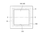
- FIG. 5A is a plan view schematically showing a configuration example of the porous resin layer and the adhesive interface of the water-repellent film in the metal-air battery.
- FIG. 5B is a sectional view taken along the line BB of FIG. 5A.
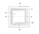
- FIG. 6A is a plan view schematically showing another configuration example of the porous resin layer of the water-repellent film and the adhesive interface in the metal-air battery.
- FIG. 6B is a sectional view taken along the line CC of FIG. 6A.
- FIG. 7A is a plan view schematically showing a configuration example of the porous resin layer and the adhesive interface of the water-repellent film of the metal-air battery according to the second embodiment of the present disclosure.
- FIG. 7B is a sectional view taken along the line DD of FIG. 7A.
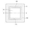
- FIG. 8A is a plan view schematically showing another configuration example of the porous resin layer and the adhesive interface of the water-repellent film of the metal-air battery.
- FIG. 8B is a cross-sectional view taken along the line EE of FIG. 8A.
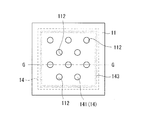
- FIG. 9A is a plan view schematically showing a configuration example of the porous resin layer and the adhesive interface of the water-repellent film of the metal-air battery according to the third embodiment of the present disclosure.
- 9B is a cross-sectional view taken along the line FF of FIG. 9A.
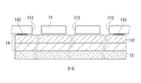
- FIG. 10A is a plan view schematically showing another configuration example of the porous resin layer of the water-repellent film and the adhesive interface in the metal-air battery.
- 10B is a sectional view taken along the line GG of FIG. 10A.
- FIG. 11 is a plan view showing a schematic configuration of the metal-air battery according to the fourth embodiment of the present disclosure.
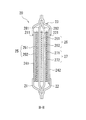
- FIG. 12 is a sectional view taken along the line HH
- FIG. 1 is a plan view showing a schematic configuration of the metal-air battery 10 according to the first embodiment
- FIG. 2 is a sectional view taken along the line AA in FIG.
- the metal-air battery 10 has a battery case (exterior body) 13 formed by adhering a first resin film 11 and a second resin film 12.
- the battery case 13 includes an air electrode 15, a metal negative electrode 16, a separator 18, and a water-repellent film 14.
- the battery case 13 is also filled with an electrolytic solution (not shown).
- the first resin film 11 and the second resin film 12 are formed of a common resin film that can be welded.
- the separator 18 is arranged so as to face the first resin film 11, and the peripheral edge portion of the separator 18 is adhered to the peripheral edge portion of the first resin film 11.
- An air electrode 15 and a water-repellent film 14 are accommodated between the first resin film 11 and the separator 18.
- the first resin film 11 is provided with one air intake port 111 as an opening for taking in air, and a water repellent film 14 is adhered to the air intake port 111.
- the air electrode 15 is arranged between the water repellent film 14 and the separator 18. Details of the air intake port 111 and the water repellent film 14 will be described later.
- the second resin film 12 is arranged on the opposite side of the first resin film 11 so as to face the separator 18.
- the peripheral edge portion of the second resin film 12 is adhered to the peripheral edge portion of the separator 18. It is preferable that the peripheral edge portion of the second resin film 12 is also adhered to the peripheral edge portion of the first resin film 11.
- a metal negative electrode 16 is housed between the second resin film 12 and the separator 18.
- the air electrode 15 includes a current collector 151 and a catalyst layer 152 in contact with the current collector 151, and is a positive electrode having an oxygen reducing ability and an oxygen generating ability.
- a part of the current collector 151 is extended to the outside of the exterior body to form a lead portion 153 of the metal-air battery 10.
- the current collector 151 is not particularly limited as long as it is a material generally used in the field of metal-air batteries.
- the thickness of the current collector 151 is preferably 0.05 mm to 0.5 mm.
- the catalyst layer 152 contains at least an air electrode catalyst.
- the air electrode catalyst is a catalyst having at least a redox ability.
- Examples of the air electrode catalyst include conductive carbons such as Ketjen black, acetylene black, denka black, carbon nanotubes, and fullerenes, metals, metal oxides, metal hydroxides, metal sulfides, and the like. Two or more types can be used.
- the catalyst layer 152 may contain a catalyst such as manganese dioxide. Further, when the metal-air battery 10 is a secondary battery, the catalyst layer 152 may include not only an air electrode catalyst having an oxygen reducing ability but also a catalyst having an oxygen generating ability, and the oxygen generating ability and the oxygen reducing ability may be contained. You may have both.
- the thickness of the catalyst layer 152 is preferably 0.1 mm or more and 1.0 mm or less.
- the metal negative electrode 16 is housed between the second resin film 12 and the separator 18 in a state where the active material layer 162 is laminated on the current collector 161.
- the current collector 161 and the particulate negative electrode active material may be separately charged and laminated.
- the metal negative electrode 16 may include a current collector 161 and a colloidal slurry in which particles of a negative electrode active material and an electrolytic solution are mixed. The slurry is preferably such that the ratio of the weight of the electrolytic solution to the weight of the negative electrode active material is 0.3 to 2.0.
- the negative electrode active material is appropriately adopted from materials generally used in the field of metal-air batteries.
- the negative electrode active material metal species such as zinc type, cadmium type, lithium type, sodium type, magnesium type, lead type, tin type, aluminum type, and iron type can be used. Since the negative electrode active material is reduced by being charged, it may be in the state of a metal oxide.
- the negative electrode active material preferably has an average particle size of 1 nm to 500 ⁇ m. It is more preferably 5 nm to 300 ⁇ m, further preferably 100 nm to 250 ⁇ m, and particularly preferably 200 nm to 200 ⁇ m.
- the average particle size can be measured using a particle size distribution measuring device.
- a part of the current collector 161 is extended to the outside of the exterior body to form a lead portion 163 of the metal-air battery 10.
- the thickness of the current collector 161 is preferably 0.05 mm to 0.50 mm.
- the thickness of the active material layer 162 is preferably 1.0 mm to 10.0 mm.
- any of the air electrode 15, the metal negative electrode 16, the separator 18, and the electrolytic solution can be conventionally used in the fields of laminated batteries and metal-air batteries.
- the resin film constituting the first resin film 11 and the second resin film 12 is preferably formed of a thermoplastic resin material having excellent alkali resistance, and more preferably, a multi-layer structure in which a plurality of resin films are laminated. Is to have.
- the thermoplastic resin material constituting such a resin film include polyolefin resins such as polypropylene and polyethylene.
- the first resin film 11 has a multi-layer structure, it is preferable that at least the surface of the first resin film 11 facing the water-repellent film 14 is a resin film layer containing a polyolefin resin.
- Polyolefin-based resin is a general term for polymers synthesized using an alkene as a monomer.
- the first resin film 11 is provided with one substantially rectangular air intake port 111 penetrating both front and back surfaces (inside and outside of the battery case 13) as an opening for taking in air at a substantially central portion. .. As shown in FIG. 2, the water-repellent film 14 is arranged so as to cover the air intake port 111 from the inside.
- FIG. 3 is a cross-sectional view schematically showing a first resin film 11, a water-repellent film 14, and an air electrode (positive electrode) 15 constituting the metal-air battery 10 in a partially enlarged manner.
- 4A and 4B are enlarged cross-sectional views of the M portion in FIG.
- air oxygen
- the electrolytic solution in the battery case 13 for example, inside the first resin film 11
- a water-repellent film 14 is arranged so as to cover the air intake port 111 in order to suppress leakage from the 111.
- An air electrode 15 (and a separator 18) is superposed on the water repellent film 14.
- the first resin film 11 is provided with one air intake port 111 in a rectangular shape as an opening penetrating inside and outside the battery case 13.
- the water-repellent film 14 has a rectangular shape having an outer shape larger than that of the air intake port 111.
- the water-repellent film 14 is arranged so as to overlap the air intake port 111 from the inside of the battery case 13.
- the water-repellent film 14 is a film that has water repellency and is capable of allowing air to pass through.
- the water repellent membrane 14 is a porous membrane having a large number of pores and has a gas-liquid separation function.
- the material of the water-repellent film 14 is generally used in the field of metal-air batteries, and is a material that can be fixed to the first resin film 11.
- Specific examples of the water-repellent film 14 include a film (microporous film and the like) made of a fluorine-containing resin such as PTFE (polytetrafluoroethylene).
- the first resin film 11 and the water-repellent film 14 are fixed via the adhesive interface 143.
- the water repellent film 14 has a large number of pores 140.
- An adhesive interface 143 of a welded resin 142 containing at least one type of polyolefin resin is formed on the water-repellent film 14 on the side facing the first resin film 11. As a result, the water-repellent film 14 is adhered to the first resin film 11.
- the adhesive interface 143 is configured by embedding a welding resin 142 in the surface layer portion of the pores 140 of the water-repellent film 14.
- the welding resin 142 is configured to contain a polyolefin-based resin.
- the water-repellent film 14 may be configured to have a porous resin layer 141 on the surface layer portion in contact with the first resin film 11 so as to cover the air intake port 111.
- the first resin film 11 is faced with the first resin film 11 and is overlapped and adhered.
- the polyolefin resin (welded resin 142) constituting the molten porous resin layer 141 permeates into the pores 140 of the water repellent film 14 and solidifies, so that the water repellent film 14 and the first resin film 11 are formed.
- An adhesive interface 143 is provided between them.
- the water-repellent film 14 and the first resin film 11 are integrally adhered to each other via the adhesive interface 143, and the water-repellent film 14 is fixed to the first resin film 11.
- the welding means of the first resin film 11 and the water-repellent film 14 is preferably heat welding.
- a more preferable embodiment of the polyolefin-based resin (welded resin 142) arranged between the first resin film 11 and the water-repellent film 14 is shown below.
- the porous resin layer 141 containing the polyolefin resin may be integrally provided on the surface layer portion of the water-repellent film 14. Further, as the porous resin layer 141, a non-woven fabric made of a polyolefin resin may be welded to the surface of the water-repellent film 14 and integrally provided on the water-repellent film 14.
- FIG. 5A is a plan view schematically showing a configuration example of the porous resin layer 141 of the water-repellent film 14 and the adhesive interface 143
- FIG. 5B is a sectional view taken along the line BB of FIG. 5A.
- the adhesive interface 143 between the first resin film 11 and the water-repellent film 14 is provided outward from the opening edge of the air intake port 111 of the first resin film 11 with a predetermined width.
- the water-repellent film 14 is provided with a porous resin layer 141 on the entire upper surface thereof.
- the porous resin layer 141 is arranged on the surface facing the first resin film 11, and the first resin film 11 and the water-repellent film 14 are fixed via the adhesive interface 143.
- the water-repellent film 14 and the porous resin layer 141 included in the water-repellent film 14 have an area larger than the opening area of the air intake port 111. Therefore, the porous resin layer 141 is configured to have a region sufficiently overlapping with the air intake port 111 of the first resin film 11. Then, by welding in all the overlapping regions of the first resin film 11 and the porous resin layer 141, the bonding interface 143 of the polyolefin resin is formed between the first resin film 11 and the water repellent film 14. It is provided.
- the adhesive interface 143 is continuously formed in a rectangular shape along the four circumferences of the air intake port 111.
- FIG. 6A is a plan view schematically showing another configuration example of the porous resin layer 141 of the water-repellent film 14 and the adhesive interface 143
- FIG. 6B is a sectional view taken along the line CC of FIG. 5A.
- the water-repellent film 14 and the porous resin layer 141 have an area larger than the opening area of the air intake port 111.
- the water-repellent film 14 is provided with a porous resin layer 141 on the entire upper surface thereof.
- the first resin film 11 and the water-repellent film 14 are arranged in an overlapping manner, and only the welded region is different. That is, as shown in FIGS. 6A and 6B, the adhesive interface 143 is formed by welding in a part of the overlapping region of the first resin film 11 and the porous resin layer 141.
- the adhesive interface 143 is continuously formed in a rectangular shape along the four circumferences of the air intake port 111, and is provided outside the air intake port 111.
- the water-repellent film 14 covers the entire air intake port 111 and is fixed to the first resin film 11 via the adhesive interface 143.
- the thickness of the water-repellent film 14 is preferably 0.05 mm to 0.5 mm, for example, whereas the porous resin layer 141 preferably has a thickness of 50 ⁇ m to 150 ⁇ m. If the thickness of the porous resin layer 141 is less than 50 ⁇ m, the welded resin 142 does not easily penetrate into the pores 140 of the water-repellent film 14, and the welded resin 142 does not sufficiently weld and the adhesive strength cannot be obtained. Further, if the thickness of the porous resin layer 141 exceeds 150 ⁇ m, it becomes difficult to melt the entire thickness of the porous resin layer 141, and there is a possibility that a porous portion that is not welded may be left, and the electrolytic solution leaks from there. This is because there is a risk of doing so.
- the porous resin layer 141 has a porosity of 65% or more and 90% or less. If the porosity is less than 65%, the gas permeability is low, which may hinder the battery reaction and deteriorate the battery characteristics. Further, if the porosity exceeds 90%, the welded resin 142 that has penetrated into the pores 140 of the water-repellent film 14 may not be sufficiently solidified.
- the porosity of the water-repellent film 14 is preferably 20% or more and 60% or less. If the porosity of the water-repellent membrane 14 is less than 20%, the gas permeability may decrease due to the permeation and solidification of the polyolefin resin into the pores 140 of the water-repellent membrane 14. Further, if the porosity of the water-repellent film 14 exceeds 60%, the water repellency and the liquid leakage resistance of the water-repellent film 14 may decrease.
- the polyolefin-based resin contained in the first resin film 11 and the porous resin layer 141 contains the same kind of first polyolefin-based resin. This is because the configurations containing the same type of polyolefin resin are used so that the resins are compatible with each other and firmly adhere to each other at the bonding interface 143.
- the porous resin layer 141 may be configured to further contain a second polyolefin-based resin different from the first polyolefin-based resin.
- the first polyolefin resin contained in both the first resin film 11 and the porous resin layer 141 is compatible with each other to obtain strong adhesion, while the porous resin layer 141 contains the second polyolefin resin. This is because the strength can be maintained and the dimensional change of the porous resin layer 141 can be suppressed at the time of welding or the like.
- the porous resin layer 141 may be formed of a fiber having a core-shell structure having a first polyolefin-based resin as a shell and a second polyolefin-based resin as a core.
- the melting points of the first polyolefin-based resin and the second polyolefin-based resin are preferably higher in the second polyolefin-based resin, for example, 20 to 70 ° C. higher.
- the first polyolefin-based resin is polyethylene
- the second polyolefin-based resin is polypropylene.
- the first resin film 11 including the air intake port 111 of the battery case 13 and the water-repellent film 14 that closes the air intake port 111 have an adhesive interface 143. It is well adhered to the first resin film 11 and fixed without forming a gap between the first resin film 11 and the water-repellent film 14. As a result, the decrease in the water level of the electrolytic solution in the metal-air battery 10 can be suppressed, and the decrease in the battery capacity can be suppressed.
- a water-repellent film 14 is laminated on a first resin film 11 having an air intake port 111.
- the water-repellent film 14 is arranged so that the porous resin layer 141 is overlapped so as to face the air intake port 111.
- all or a part of the overlapping region of the porous resin layer 141 and the first resin film 11 is continuously welded on four circumferences at the peripheral edge of the air intake port 111.
- the water-repellent film 26 is adhered to the first resin film 21.
- the adhesive interface 143 of the welded resin 142 is provided between the first resin film 11 and the water-repellent film 14, and the water-repellent film 14 is fixed to the first resin film 11.
- the catalyst layer 152 of the air electrode 15 and the current collector 151 are laminated on the water-repellent membrane 14, and these are pressure-bonded by a press. Further, the separator 18 is laminated on the current collector 151, and the separator 18 is welded to the first resin film 11. As shown in FIG. 2, the separator 18 has a larger area than the water-repellent film 14, and the overlapping portion of the separator 18 and the first resin film 11 is welded.
- the area ratio of the separator 18 to the area of the first resin film 11 including the opening area of the air intake port 111 is preferably 0.55 to 0.95.
- the current collector 161 of the metal negative electrode 16 is laminated on the separator 18.
- the second resin film 22 is laminated so as to face the current collector 161 and the three sides except the lower side are adhered to each other. At this time, at least the portions where the resin films (the first resin film 11 and the second resin film 22) overlap each other are welded on the two sides. Further, on the upper side, at least a portion where the first resin film 11, the second resin film 22, and the separator 18 overlap is welded.
- the water-repellent film 14 is provided with the porous resin layer 141, and the porous resin layer 141 and the first resin film 11 are welded to each other to ensure between them.
- the adhesive interface 143 can be provided on the surface. Further, since the separator 18 is adhered to the first resin film 11 constituting the battery case 13, the metal-air battery 10 can be easily assembled by laminating and adhering the members. Therefore, the manufacturing process can be simplified and the cost can be reduced.
- FIG. 7A and 7B schematically show a configuration example of the first resin film 11 and the water-repellent film 14 in the metal-air battery 10 according to the second embodiment of the present disclosure
- FIG. 7A is a plan view
- FIG. 7B is a plan view
- FIG. 7A is a sectional view taken along the line DD of FIG. 7A.
- the water-repellent film 14 has a configuration in which the porous resin layer 141 is provided on the entire upper surface, which is the surface facing the first resin film 11.
- the porous resin layer 141 is not limited to being provided on the entire upper surface of the water-repellent film 14, but may be provided on a part of the upper surface of the water-repellent film 14.
- the water-repellent film 14 is arranged so as to cover the entire air intake port 111 of the first resin film 11, while the water-repellent film 14 has a porous resin on the outer peripheral portion of the upper surface.
- Layer 141 is provided.
- the porous resin layer 141 of the water-repellent film 14 is provided so as to have a region overlapping with the first resin film 11, and does not have to cover the entire air intake port 111.
- the porous resin layer 141 is made of a non-woven fabric made of a polyolefin resin
- the porous resin layer 141 may be provided with an opening having an area smaller than that of the air intake port 111.
- the adhesive interface 143 between the first resin film 11 and the water-repellent film 14 is provided outward from the opening edge of the air intake port 111 of the first resin film 11 with a predetermined width. Further, as shown in FIG. 7B, the porous resin layer 141 is arranged on the surface facing the first resin film 11, and the first resin film 11 and the water-repellent film 14 are fixed via the adhesive interface 143. There is.
- the first resin film 11 and the porous resin layer 141 may be welded in a part of the region where they overlap each other.
- 8A is a plan view schematically showing another configuration example of the porous resin layer 141 of the water-repellent film 14 and the adhesive interface 143
- FIG. 8B is a sectional view taken along the line EE of FIG. 5A.
- the water-repellent film 14 is provided with a porous resin layer 141 on the outer peripheral portion of the upper surface thereof, and has an opening having an area smaller than that of the air intake port 111.
- the water-repellent film 14 is laminated so as to arrange the porous resin layer 141 on the surface facing the first resin film 11, and in a part of the overlapping region of the first resin film 11 and the porous resin layer 141.
- the adhesive interface 143 is formed by welding.
- the adhesive interface 143 is continuously formed in a rectangular shape along the four circumferences of the air intake port 111, and is provided outside the air intake port 111.
- the water-repellent film 14 covers the entire air intake port 111 and is fixed to the first resin film 11 via the adhesive interface 143.
- the first resin film 11 provided with the air intake port 111 and the water-repellent film 14 that closes the air intake port 111 are satisfactorily adhered to each other via the adhesive interface 143. It is adhered and it is avoided that a gap is formed between the first resin film 11 and the water-repellent film 14. As a result, the decrease in the water level of the electrolytic solution is suppressed, and the decrease in the battery capacity can be suppressed.
- FIG. 9A and 9B schematically show a configuration example of the first resin film 11 and the water-repellent film 14 in the metal-air battery 10 according to the third embodiment of the present disclosure
- FIG. 9A is a plan view
- FIG. 9B is a plan view
- 9A is a cross-sectional view taken along the line FF of FIG. 9A.
- the first resin film 11 is provided with one rectangular air intake port 111.
- the first resin film 11 is not limited to having one air intake port, and may have a configuration having a plurality of air intake ports.
- the first resin film 11 may be provided with a plurality of circular air intake ports 112.
- the water-repellent film 14 is provided with a porous resin layer 141 on the entire upper surface thereof.
- the porous resin layer 141 is arranged on the surface facing the first resin film 11, and the first resin film 11 and the water-repellent film 14 are fixed via the adhesive interface 143.
- the water-repellent film 14 and the porous resin layer 141 included in the water-repellent film 14 have an area that covers all of the plurality of air intake ports 112. Therefore, the porous resin layer 141 has a region sufficiently overlapping with the plurality of air intake ports 112 of the first resin film 11.
- the bonding interface 143 of the polyolefin resin is provided between the first resin film 11 and the water repellent film 14. ing.
- the first resin film 11 and the porous resin layer 141 may be welded in a part of the region where they overlap each other, as in the above embodiment.
- 10A is a plan view schematically showing another configuration example of the porous resin layer 141 of the water-repellent film 14 and the adhesive interface 143 in the third embodiment
- FIG. 10B is a sectional view taken along the line GG of FIG. 10A. ..
- the water-repellent film 14 is provided with the porous resin layer 141 over the entire upper surface, while the adhesive interface 143 is a part of the overlapping region of the first resin film 11 and the porous resin layer 141. It is formed by welding in.
- the adhesive interface 143 is formed in a rectangular shape along the outer peripheral portion of the water-repellent film 14. As shown in FIG. 10A, the adhesive interface 143 is continuously formed in a rectangular shape outside the region provided with the plurality of air intake ports 112. The water-repellent film 14 is arranged so as to cover all the air intake ports 112, and is fixed to the first resin film 11 via the adhesive interface 143.
- the first resin film 11 having a plurality of air intake ports 112 and the water-repellent film 14 that closes the air intake ports 111 are interposed via an adhesive interface 143. It adheres well and avoids the formation of a gap between the first resin film 11 and the water-repellent film 14. As a result, the decrease in the water level of the electrolytic solution can be suppressed, and the decrease in the battery capacity can be suppressed.
- FIG. 11 is a plan view showing a schematic configuration of the metal-air battery 20 according to the fourth embodiment
- FIG. 12 is a sectional view taken along the line HH of FIG.
- the metal-air battery 20 is characterized in that it is a three-pole type, and the structure of the adhesive interface made of the welding resin can be the same as that of the first to third embodiments.
- the metal-air battery 20 constitutes a battery case (exterior body) 23 by laminating a first resin film 21 and a second resin film 12, and has an air electrode (air electrode) inside the battery case 23. It includes a first positive electrode) 25, a metal negative electrode 26, a charging electrode (second positive electrode) 27, a first separator 281, a second separator 282, a first water repellent film 241 and a second water repellent film 242.
- the inside of the battery case 23 is also filled with an electrolytic solution (not shown).
- the first separator 281 is arranged so as to face the first resin film 21, and the peripheral edge portion of the first separator 281 is adhered to the peripheral edge portion of the first resin film 21.
- An air electrode 25 and a first water-repellent film 241 are accommodated between the first resin film 21 and the first separator 281.
- the first resin film 21 is formed with an air intake port 211 as an opening for taking in air, and the first water-repellent film 241 covers the air intake port 211 in the first resin film 21. It is welded.
- the air electrode 25 is arranged between the first water repellent film 241 and the first separator 281.
- the thickness of the first separator 281 is preferably 0.05 mm to 0.40 mm.
- the thickness of the first water-repellent film 241 is preferably 0.05 mm to 0.50 mm.
- the second separator 282 is arranged so as to face the second resin film 22, and the peripheral edge portion of the second separator 282 is adhered to the peripheral edge portion of the second resin film 22.
- a charging electrode 27 and a second water-repellent film 242 are accommodated between the second resin film 22 and the second separator 282.
- the second resin film 22 is formed with an air discharge port 221 as an opening for discharging air, and the second water-repellent film 242 is welded to the second resin film 22 so as to cover the air discharge port 221. Has been done.
- the charging electrode 27 is arranged between the second water-repellent film 242 and the second separator 282.
- the thickness of the second separator 282 is preferably 0.05 mm to 0.40 mm.
- the thickness of the second water-repellent film 242 is preferably 0.05 mm to 0.50 mm.
- the first separator 281 and the second separator 282 are arranged so as to face each other, and the peripheral edges of the first separator 281 and the second separator 282 are adhered to each other by heat welding, ultrasonic welding, or the like. That is, the first separator 281 and the second separator 282 in which the peripheral portions are adhered to each other form a bag-shaped separator, and the peripheral edge portion of the bag-shaped separator is fixed to the exterior body. Further, it is preferable that the peripheral portions of the first resin film 21 and the second resin film 22 are also adhered to each other.
- a metal negative electrode 26 is housed between the first separator 281 and the second separator 282 (inside the bag-shaped separator).
- the peripheral edge of the first separator 281 and the second separator 282 are adhered to each other to form a bag-shaped separator, but strictly speaking, the peripheral edge of the first separator 281 is the first resin film 21. It suffices that the peripheral portion of the second separator 282 is adhered to the peripheral edge portion and the peripheral edge portion of the second separator 282 is adhered to the peripheral edge portion of the second resin film 22.
- the metal air battery 20 is provided with the first water-repellent film 241 and the second water-repellent film 242 in order to prevent leakage of the electrolytic solution from the air intake port 211 and the air discharge port 221 which are openings. It has a gas-liquid separation function, and is between the first water-repellent film 241 and the first resin film 21 and between the second water-repellent film 242 and the second resin film 22. Similarly, an adhesive interface for the welded resin is provided.
- the first water-repellent film 241 and the second water-repellent film 242 may have a porous resin layer provided on the entire upper surface thereof, or may have a porous resin layer provided on a part of the upper surface thereof.
- the air electrode 25 is composed of a current collector 251 and a catalyst layer 252, and can have the same configuration as the air electrode 15 shown in the above embodiment.
- the charging electrode 27 is composed of a current collector 271 and a catalyst layer 272.
- the catalyst layer 272 may include, for example, a conductive porous carrier and a charging electrode catalyst supported on the porous carrier.
- This charging electrode catalyst is a catalyst having an oxygen generating ability (nickel or the like), and promotes a charging reaction when the metal-air battery 20 is charged.
- the catalyst layer 272 is made of, for example, nickel foam.
- a part of the current collectors 251, 271 is extended to the outside of the battery case 23 to form the lead portions 253 and 273 of the metal-air battery 20.
- the metal negative electrode 26 has a form in which the active material layer 262 is laminated on the current collector 261 and can have the same configuration as the metal negative electrode 16 in the first embodiment. A part of the current collector 261 is extended to the outside of the battery case 23 to form a lead portion 263 of the metal-air battery 20.
- the metal air battery 20 at least between the first resin film 21 and the first water repellent film 241 of the battery case 23, and with the second resin film 22 as in the first to third embodiments.
- an adhesive interface (143) of the welded resin (142) is provided between the second water-repellent film 242 and the second water-repellent film 242.
- the air intake port 211 provided in the first resin film 21 and the air discharge port 221 provided in the second resin film 22 may be one or a plurality, and the shape is limited to a rectangular shape. Instead, it may have a circular shape (see FIG. 9A and the like).
- the first resin film 21 and the porous resin layer of the first water-repellent film 241 are welded in the entire region where they overlap each other (see FIGS. 5A and 7A), and the first resin film 21 is welded.
- An adhesive interface of a polyolefin resin may be provided between the resin film 21 and the first water-repellent film 241, or an adhesive interface may be provided by welding in a part of these overlapping regions (FIG. 6A). , See FIG. 8A).
- the first resin film 21 and the first water-repellent film 241 of the battery case 23, and the first water-repellent film 241 and the like as in the metal-air battery 10 shown in the first to third embodiments.
- the second resin film 22 and the second water-repellent film 242 are well adhered to each other, the leakage of the electrolytic solution can be suppressed, and the battery performance can be improved.
Landscapes
- Engineering & Computer Science (AREA)
- Manufacturing & Machinery (AREA)
- Chemical & Material Sciences (AREA)
- Chemical Kinetics & Catalysis (AREA)
- Electrochemistry (AREA)
- General Chemical & Material Sciences (AREA)
- Hybrid Cells (AREA)
- Sealing Battery Cases Or Jackets (AREA)
Priority Applications (1)
| Application Number | Priority Date | Filing Date | Title |
|---|---|---|---|
| JP2022535015A JP7487308B2 (ja) | 2020-07-10 | 2021-06-24 | 金属空気電池および金属空気電池の製造方法 |
Applications Claiming Priority (2)
| Application Number | Priority Date | Filing Date | Title |
|---|---|---|---|
| JP2020-119406 | 2020-07-10 | ||
| JP2020119406 | 2020-07-10 |
Publications (1)
| Publication Number | Publication Date |
|---|---|
| WO2022009688A1 true WO2022009688A1 (ja) | 2022-01-13 |
Family
ID=79553040
Family Applications (1)
| Application Number | Title | Priority Date | Filing Date |
|---|---|---|---|
| PCT/JP2021/023932 Ceased WO2022009688A1 (ja) | 2020-07-10 | 2021-06-24 | 金属空気電池および金属空気電池の製造方法 |
Country Status (2)
| Country | Link |
|---|---|
| JP (1) | JP7487308B2 (https=) |
| WO (1) | WO2022009688A1 (https=) |
Citations (2)
| Publication number | Priority date | Publication date | Assignee | Title |
|---|---|---|---|---|
| JP2019067754A (ja) * | 2017-09-28 | 2019-04-25 | マクセルホールディングス株式会社 | シート状空気電池およびパッチ |
| WO2019203129A1 (ja) * | 2018-04-18 | 2019-10-24 | シャープ株式会社 | 金属空気電池および金属空気電池の製造方法 |
-
2021
- 2021-06-24 JP JP2022535015A patent/JP7487308B2/ja active Active
- 2021-06-24 WO PCT/JP2021/023932 patent/WO2022009688A1/ja not_active Ceased
Patent Citations (2)
| Publication number | Priority date | Publication date | Assignee | Title |
|---|---|---|---|---|
| JP2019067754A (ja) * | 2017-09-28 | 2019-04-25 | マクセルホールディングス株式会社 | シート状空気電池およびパッチ |
| WO2019203129A1 (ja) * | 2018-04-18 | 2019-10-24 | シャープ株式会社 | 金属空気電池および金属空気電池の製造方法 |
Also Published As
| Publication number | Publication date |
|---|---|
| JP7487308B2 (ja) | 2024-05-20 |
| JPWO2022009688A1 (https=) | 2022-01-13 |
Similar Documents
| Publication | Publication Date | Title |
|---|---|---|
| JP7004461B2 (ja) | 金属空気電池および金属空気電池の製造方法 | |
| JP2017027735A (ja) | 金属空気電池の負極複合体及び金属空気電池 | |
| CN108539204B (zh) | 锂空气电池的负极复合体结构 | |
| JPWO2019193882A1 (ja) | 非水電解質二次電池用電極板及び非水電解質二次電池 | |
| CN109075413B (zh) | 锂空气电池的负极复合体构造 | |
| JP7487308B2 (ja) | 金属空気電池および金属空気電池の製造方法 | |
| JP7299995B2 (ja) | ラミネート電池およびその製造方法 | |
| JP2021068492A (ja) | 非水電解質二次電池 | |
| JP2006236775A (ja) | 二次電池 | |
| CN109428084B (zh) | 空气电池和使用于该空气电池的负极复合体 | |
| JP2021061161A (ja) | 電気化学セル | |
| JP7223114B2 (ja) | 負極および金属空気電池 | |
| JP7487307B2 (ja) | 金属空気電池の製造方法 | |
| JP2024044037A (ja) | 蓄電モジュール及び蓄電装置 | |
| JP7091965B2 (ja) | 空気電池およびそれに用いる負極複合体 | |
| US11063310B2 (en) | Battery case and metal-air battery having same | |
| CN114616707B (zh) | 层叠电池 | |
| US20260081181A1 (en) | Current collector and battery | |
| JP2018026207A (ja) | リチウム空気電池の正極構造 | |
| KR20230154738A (ko) | 가스 배출 부재 및 이를 구비한 이차전지 | |
| JP2022015635A (ja) | 金属空気電池 |
Legal Events
| Date | Code | Title | Description |
|---|---|---|---|
| 121 | Ep: the epo has been informed by wipo that ep was designated in this application |
Ref document number: 21837401 Country of ref document: EP Kind code of ref document: A1 |
|
| ENP | Entry into the national phase |
Ref document number: 2022535015 Country of ref document: JP Kind code of ref document: A |
|
| NENP | Non-entry into the national phase |
Ref country code: DE |
|
| 122 | Ep: pct application non-entry in european phase |
Ref document number: 21837401 Country of ref document: EP Kind code of ref document: A1 |