WO2022004496A1 - センサーおよびバンドパスフィルター - Google Patents
センサーおよびバンドパスフィルター Download PDFInfo
- Publication number
- WO2022004496A1 WO2022004496A1 PCT/JP2021/023649 JP2021023649W WO2022004496A1 WO 2022004496 A1 WO2022004496 A1 WO 2022004496A1 JP 2021023649 W JP2021023649 W JP 2021023649W WO 2022004496 A1 WO2022004496 A1 WO 2022004496A1
- Authority
- WO
- WIPO (PCT)
- Prior art keywords
- liquid crystal
- layer
- cholesteric liquid
- light
- bandpass
- Prior art date
- Legal status (The legal status is an assumption and is not a legal conclusion. Google has not performed a legal analysis and makes no representation as to the accuracy of the status listed.)
- Ceased
Links
Images

Classifications
-
- G—PHYSICS
- G01—MEASURING; TESTING
- G01B—MEASURING LENGTH, THICKNESS OR SIMILAR LINEAR DIMENSIONS; MEASURING ANGLES; MEASURING AREAS; MEASURING IRREGULARITIES OF SURFACES OR CONTOURS
- G01B11/00—Measuring arrangements characterised by the use of optical techniques
- G01B11/24—Measuring arrangements characterised by the use of optical techniques for measuring contours or curvatures
- G01B11/25—Measuring arrangements characterised by the use of optical techniques for measuring contours or curvatures by projecting a pattern, e.g. one or more lines, moiré fringes on the object
-
- G—PHYSICS
- G01—MEASURING; TESTING
- G01S—RADIO DIRECTION-FINDING; RADIO NAVIGATION; DETERMINING DISTANCE OR VELOCITY BY USE OF RADIO WAVES; LOCATING OR PRESENCE-DETECTING BY USE OF THE REFLECTION OR RERADIATION OF RADIO WAVES; ANALOGOUS ARRANGEMENTS USING OTHER WAVES
- G01S7/00—Details of systems according to groups G01S13/00, G01S15/00, G01S17/00
- G01S7/48—Details of systems according to groups G01S13/00, G01S15/00, G01S17/00 of systems according to group G01S17/00
- G01S7/481—Constructional features, e.g. arrangements of optical elements
-
- G—PHYSICS
- G02—OPTICS
- G02B—OPTICAL ELEMENTS, SYSTEMS OR APPARATUS
- G02B5/00—Optical elements other than lenses
- G02B5/20—Filters
- G02B5/26—Reflecting filters
-
- G—PHYSICS
- G02—OPTICS
- G02B—OPTICAL ELEMENTS, SYSTEMS OR APPARATUS
- G02B5/00—Optical elements other than lenses
- G02B5/30—Polarising elements
- G02B5/3016—Polarising elements involving passive liquid crystal elements
-
- G—PHYSICS
- G02—OPTICS
- G02B—OPTICAL ELEMENTS, SYSTEMS OR APPARATUS
- G02B7/00—Mountings, adjusting means, or light-tight connections, for optical elements
- G02B7/008—Mountings, adjusting means, or light-tight connections, for optical elements with means for compensating for changes in temperature or for controlling the temperature; thermal stabilisation
Definitions
- the present invention relates to a sensor and a bandpass filter used in a distance measuring device or the like.
- Distance measurement sensors for measuring the distance to an object are used for motion capture, automatic driving of automobiles, automatic control of robots, etc.
- Patent Document 1 in a so-called time-of-flight type distance measuring sensor (optical distance sensor), the distance of a distance measuring object is calculated from the phase shift between the blinking infrared rays and the reflected light by the distance measuring object. It is stated that. Specifically, in Patent Document 1, infrared rays are emitted to a distance measurement object as blinking light corresponding to a light emission signal, and the infrared rays reflected from the distance measurement object are received to generate a light receiving signal to generate a light emission signal. It is described that the time difference, that is, the phase difference of the waveform (for example, pulse waveform) between the light receiving signal and the received signal is obtained, and the distance between the optical distance sensor and the distance measurement object is obtained based on this phase difference.
- the time difference that is, the phase difference of the waveform (for example, pulse waveform) between the light receiving signal and the received signal is obtained, and the distance between the optical distance sensor and the distance measurement object is obtained based on this phase difference.
- a distance measuring sensor not only such a distance measuring sensor, but also a sensor that performs optical measurement, for example, emits measurement light from a light source, measures the measurement light reflected by an object with a light receiving element, and analyzes the measurement result. , Make various measurements.
- the external light includes light in the wavelength range emitted by the light source and light having sensitivity of the light receiving element.
- the SN ratio signal-noise ratio
- a narrow band bandpass filter is used to extract light of the emission wavelength of the light source, cut light of other wavelengths, and suppress external light incident on the light receiving element to suppress noise. Is being done. The narrower the half-value width of the passing peak of the bandpass filter, the more effectively it is possible to suppress the incident of external light on the light receiving element, so that the SN ratio can be further improved.
- the emission wavelength of the light source changes with changes in the environmental temperature. Specifically, the higher the temperature, the longer the emission wavelength of the light source.
- a narrow band bandpass filter made of a general inorganic material has almost no change in the passing wavelength with respect to a temperature change. Therefore, when a bandpass filter with a narrow half-value width is used, when the ambient temperature changes, the emission wavelength of the light source and the passing wavelength of the bandpass filter are deviated, and the light source is incident on the light receiving element. Since the amount of light of the passing wavelength is reduced, the SN ratio is lowered.
- a bandpass filter with a wide half-value width of the passing peak it is possible to suppress the deviation between the emission wavelength of the light source and the passing wavelength of the bandpass filter even if the environmental temperature changes, but the half-value width of the bandpass filter If the width is wide, the amount of external light that cannot be cut increases, so noise cannot be sufficiently suppressed and the SN ratio decreases.
- a light source having a narrow half-value width of the emission peak wavelength such as a laser light source and an LED (light emitting diode) light source used for a distance measuring sensor, is used, the influence of the deviation of the emission wavelength due to a change in the environmental temperature becomes large. Therefore, the decrease in the SN ratio is large when the environmental temperature changes.
- An object of the present invention is to solve such a problem of the prior art, and in a sensor used for a distance measuring sensor or the like, a high SN ratio can be obtained even if the environmental temperature changes, and high-precision measurement can be performed. It is an object of the present invention to provide a sensor that can be used and a band pass filter used for the sensor.
- the present invention has the following configurations.
- Light source and A bandpass filter that extracts light with the emission peak wavelength of the light source, It has a light receiving element that receives the light extracted by the bandpass filter, and has.
- the bandpass filter has a bandpass layer and a support that supports the bandpass layer. Assuming that the coefficient of thermal expansion of the bandpass layer is ⁇ 1, the elastic modulus is E1, the coefficient of thermal expansion of the support is ⁇ 2, and the elastic modulus is E2. ⁇ 1> ⁇ 2 E1 ⁇ E2 Sensor that meets. [2] The sensor according to [1], wherein the half width of the emission peak of the light source is 30 nm or less.
- the bandpass layer contains an organic material.
- the bandpass filter transmits light of the emission peak wavelength of the light source and extracts light of the emission peak wavelength of the light source.
- the bandpass filter reflects the light having the emission peak wavelength of the light source and extracts the light having the emission peak wavelength of the light source.
- the bandpass layer has a cholesteric liquid crystal layer which is a layer formed by fixing the cholesteric liquid crystal phase.
- the cholesteric liquid crystal layer has a region in which the in-plane refractive index nx in the slow-phase axial direction and the refractive index ny in the phase-advancing axis direction satisfy nx> ny.
- the cholesteric liquid crystal layer has a second selective reflection peak at a wavelength of ⁇ / 2, and the half width of the second selective reflection peak at ⁇ / 2 is 20 nm or less.
- the sensor according to any one of [1] to [10]. [12] It has a bandpass layer and a support that supports the bandpass layer. A bandpass filter having a support with a coefficient of thermal expansion ⁇ 2 of less than 0 ppm / ° C. [13]
- the bandpass layer has a cholesteric liquid crystal layer which is a layer formed by fixing the cholesteric liquid crystal phase.
- the bandpass layer has a cholesteric liquid crystal layer which is a layer formed by fixing the cholesteric liquid crystal phase.
- the bandpass layer has a cholesteric liquid crystal layer which is a layer formed by fixing the cholesteric liquid crystal phase.
- the sensor according to any one of [1] to [9], [11], [13] and [14], wherein the cholesteric liquid crystal layer has a film thickness of 10 ⁇ m or more.
- the bandpass layer has a cholesteric liquid crystal layer which is a layer formed by fixing the cholesteric liquid crystal phase.
- the cholesteric liquid crystal layer is formed by laminating a cholesteric liquid crystal layer having a right-handed spiral structure and a cholesteric liquid crystal layer having a left-handed spiral structure, [1] to [9], [11], [13] to The sensor according to any one of [15].
- a sensor used for a distance measuring sensor or the like a sensor capable of obtaining a high SN ratio and performing highly accurate measurement even if the ambient temperature changes, and a bandpass filter used for the sensor. Can be provided.
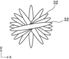
- FIG. 7 is a view of a part of the liquid crystal compound of the cholesteric liquid crystal layer of the bandpass filter shown in FIG.
- the numerical range represented by using “-” in the present specification means a range including the numerical values before and after “-” as the lower limit value and the upper limit value.
- (meth) acrylate is used to mean “either or both of acrylate and methacrylate”.
- “same”, “equal”, etc. shall include an error range generally accepted in the technical field.
- the selective reflection center wavelength is the half-value transmittance expressed by the following formula: T1 / 2 (%) when the minimum value of the transmittance in the target object (member) is Tmin (%). ) Is the average value of the two wavelengths.
- T1 / 2 100- (100-Tmin) ⁇ 2
- the sensor of the present invention Light source and A bandpass filter that extracts light with the emission peak wavelength of the light source, It has a light receiving element that receives the light extracted by the bandpass filter, and has.
- the bandpass filter has a bandpass layer and a support that supports the bandpass layer. Assuming that the coefficient of thermal expansion of the bandpass layer is ⁇ 1, the elastic modulus is E1, the coefficient of thermal expansion of the support is ⁇ 2, and the elastic modulus is E2. ⁇ 1> ⁇ 2 E1 ⁇ E2 It is a sensor that satisfies.
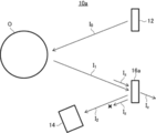
- FIG. 1 conceptually shows an example of the sensor of the present invention.
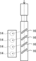
- the sensor 10a shown in FIG. 1 has a light source 12, a light receiving element 14, and a bandpass filter 16a.
- the bandpass filter 16a is a reflection type bandpass filter that extracts light in this wavelength range by reflecting only light in a predetermined wavelength range. Specifically, the bandpass filter 16a reflects the light in the wavelength range including the light having the emission peak wavelength of the light source and transmits the light in the other wavelength range to extract the light having the emission peak wavelength of the light source. It is a thing.
- the light source 12 is arranged so as to irradiate the measurement light I 0 toward the outside (object O).
- Band-pass filter 16a out of the measuring beam I 1 that is reflected by the object of O, arranged to reflect toward the measurement light I 1 incident at a predetermined angle to the light receiving element 14.
- the light receiving element 14 is arranged at a position where the measurement light I 2 reflected by the bandpass filter 16a is received.
- the object O is not limited, and may be a person, an animal, or an object.
- the measurement of the object O include measurement of the distance to the object O (distance measurement), measurement of the shape of the object O, measurement of the movement of the object O, and identification of the object O. Will be done. All of these measurements may be performed by a known method.
- the sensor 10 measures the distance to the object O by a time-of-flight method (ToF (Time of Flight)).
- ToF Time of Flight
- Such a sensor 10a measures the measurement light emitted by the light source 12 and reflected by the object O by the light receiving element 14 via the bandpass filter 16a, and analyzes the photometric result to analyze the photometric result. It measures the distance to and from (hereinafter, also referred to simply as the measurement of the object).
- the external light I z incident on the sensor such as sunlight and lighting is not reflected by the bandpass filter 16a
- the external light I z incident on the light receiving element 14 can be cut and noise is suppressed. be able to.
- the reflection wavelength band of the band-pass filter 16a outside light I z hereinafter, also referred to as the passband
- the passband is not cut by the band pass filter 16a, is incident on the light receiving element 14. Therefore, if the pass band of the bandpass filter 16a is wide, the external light Iz incident on the light receiving element 14 increases, and the SN ratio cannot be sufficiently improved. Therefore, the bandpass filter 16a is required to have a narrow pass band (narrow band).
- the emission wavelength of the light source changes with changes in the environmental temperature. Specifically, the higher the temperature, the longer the emission wavelength of the light source.
- a narrow band bandpass filter made of a general inorganic material there is almost no change in the passing wavelength with respect to a temperature change. Therefore, when a narrow band bandpass filter is used, when the ambient temperature changes, the emission wavelength of the light source and the passing wavelength of the bandpass filter are deviated, and the light source emits light incident on the light receiving element. Since the amount of light of the wavelength is reduced, the SN ratio is lowered.
- a bandpass filter with a wide half-value width of the passing peak it is possible to suppress the deviation between the emission wavelength of the light source and the passing wavelength of the bandpass filter even if the environmental temperature changes, but the half-value width of the bandpass filter If the width is wide, the amount of external light that cannot be cut increases, so noise cannot be sufficiently suppressed and the SN ratio decreases.
- the bandpass filter has a bandpass layer and a support supporting the bandpass layer, the thermal expansion coefficient of the bandpass layer is ⁇ 1, and the elastic modulus is E1.
- the support has a configuration that satisfies ⁇ 1> ⁇ 2 and E1 ⁇ E2.
- the passing wavelength of the bandpass filter changes when the environmental temperature changes. Specifically, when the environmental temperature rises, the passing wavelength of the bandpass filter shifts to the long wavelength side. Therefore, when the emission wavelength of the light source changes due to the change in the environmental temperature, the passing wavelength of the bandpass filter also changes. For example, when the ambient temperature rises and the emission wavelength of the light source becomes longer, the passing wavelength of the bandpass filter also becomes longer. Therefore, even in a narrow band bandpass filter, when the ambient temperature changes, the emission wavelength of the light source and the pass wavelength of the bandpass filter change in the same manner.
- the light having the emission wavelength of the light source can pass through the bandpass filter, the amount of light incident on the light receiving element at the passing wavelength of the light source can be prevented from decreasing, and the SN ratio can be prevented from decreasing.
- the sensor can obtain a high SN ratio even if the environmental temperature changes, and can perform highly accurate measurement. The point that the passing wavelength of the bandpass filter changes when the environmental temperature changes will be described in detail later.
- the bandpass filter 16a is a reflection type bandpass filter, but the bandpass filter 16a is not limited thereto.
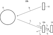
- FIG. 2 conceptually shows another example of the sensor of the present invention.
- the sensor 10b shown in FIG. 2 has a light source 12, a light receiving element 14, and a bandpass filter 16b.
- the bandpass filter 16b is a transmission type bandpass filter that extracts light in this wavelength range by transmitting only light in a predetermined wavelength range.
- the bandpass filter 16b transmits light in a wavelength range including light of the emission peak wavelength of the light source, and absorbs and / or reflects light in other wavelength ranges to obtain the emission peak wavelength of the light source. It extracts light.
- the light source 12 is arranged so as to irradiate the measurement light I 0 toward the outside (object O).
- the bandpass filter 16b is arranged so that the measurement light I 1 reflected by the object O is transmitted toward the light receiving element 14.
- the light receiving element 14 is arranged at a position where the measurement light I 3 transmitted through the bandpass filter 16a is received.
- Such a sensor 10b measures the measurement light emitted by the light source 12 and reflected by the object O by the light receiving element 14 via the bandpass filter 16b, and analyzes the photometric result to analyze the measurement result. It measures the distance to and from (hereinafter, also referred to simply as the measurement of the object). At that time, since the external light I z incident on the sensor such as sunlight and lighting does not pass through the bandpass filter 16b, the external light I z incident on the light receiving element 14 can be cut and noise is suppressed. be able to.
- the pass band Even in such a transmission type bandpass filter, when a narrow bandpass filter is used, when the ambient temperature changes, the emission wavelength of the light source and the transmission wavelength band of the bandpass filter (hereinafter referred to as the pass band). There is a problem that the SN ratio is lowered because the amount of light of the emission wavelength of the light source incident on the light receiving element is reduced.
- the senor of the present invention has a bandpass layer and a support that supports the bandpass layer even in the case of a transmission type bandpass filter, and the thermal expansion coefficient of the bandpass layer is set to ⁇ 1.
- the elastic modulus is E1
- the coefficient of thermal expansion of the support is ⁇ 2
- the elastic modulus is E2
- the configuration satisfies ⁇ 1> ⁇ 2 and E1 ⁇ E2. Since the bandpass filter has such a configuration, the passing wavelength of the bandpass filter changes when the environmental temperature changes. Therefore, even in a narrow band bandpass filter, when the ambient temperature changes, the emission wavelength of the light source and the pass wavelength of the bandpass filter change in the same manner.
- the light having the emission wavelength of the light source can pass through the bandpass filter, the amount of light incident on the light receiving element at the passing wavelength of the light source can be prevented from decreasing, and the SN ratio can be prevented from decreasing.
- the sensor can obtain a high SN ratio even if the environmental temperature changes, and can perform highly accurate measurement.
- the bandpass filter 16 when it is not necessary to distinguish between the reflection type bandpass filter 16a and the transmission type bandpass filter 16b, the bandpass filter 16 will be collectively described.
- the light source 12 is not limited, and all known light sources used as light sources in optical sensors can be used. Examples of the light source include a light bulb such as a mercury lamp, a fluorescent lamp, a halogen lamp, an LED (Light Emitting Diode), a laser such as a semiconductor laser, and the like.
- the light emitted from the light source 12 may be diffused light or parallel light such as a collimated light beam. Further, in the sensor 10, the light emitted by the light source 12 may be scanned one-dimensionally or two-dimensionally, if necessary.
- a laser Light Emitting Diode
- a laser such as a semiconductor laser, which can irradiate a narrow band light as the light source 12.
- the half width of the emission peak of the light source 12 is preferably 30 nm or less, more preferably 15 nm or less, still more preferably 10 nm or less.
- the rate of change in the emission wavelength (peak wavelength) depending on the temperature is about 0.1 nm / ° C to 0.7 nm / ° C. Is.
- the wavelength of the light emitted by the light source 12 is not limited, and may be visible light or invisible light such as infrared rays and ultraviolet rays. Among them, infrared rays, which are invisible light, are suitably used as light emitted by the light source 12. Further, the light emitted by the light source 12 may be unpolarized or polarized. When the light source 12 emits polarized light, the emitted light may be linearly polarized light or circularly polarized light.
- the light receiving element 14 is also not limited, and all known light receiving elements (photodetectors (elements)) used as light receiving elements in optical sensors can be used.
- the light receiving element 14 include a CMOS (Complementary Metal Oxide Semiconductor) sensor, a CCD (Charge-Coupled Device) sensor, and the like.
- the light receiving element 14 may not have spatial resolution, but a line sensor that detects light in a line shape or an area sensor that detects light two-dimensionally is preferable, and an area sensor is particularly preferable.
- the light receiving element 14 measures the measurement light emitted by the light source 12 and reflected by the object O via the bandpass filter 16.
- the bandpass filter has a bandpass layer and a support that supports the bandpass layer.
- the coefficient of thermal expansion of the bandpass layer is ⁇ 1
- the elastic modulus is E1
- the coefficient of thermal expansion of the support is ⁇ 2.
- the elastic modulus is E2
- a bandpass layer containing an organic material is preferably used.
- the bandpass layer include an organic dielectric multilayer film and a cholesteric liquid crystal layer.
- the dielectric multilayer film has a structure in which transparent and high refractive index films and transparent and low refractive index films are alternately laminated, and the thickness and refractive index of the high refractive index layer and the low refractive index layer are formed.
- the rate and the like By adjusting the rate and the like, light in a desired wavelength range can be reflected or transmitted, and light in another wavelength range can be transmitted or reflected. That is, in the dielectric multilayer film, the passing wavelength depends on the thickness of the high refractive index layer and the low refractive index layer.
- each layer of the dielectric multilayer film with an organic material (polymer)
- the coefficient of thermal expansion ⁇ 1 of the bandpass layer is larger than the coefficient of thermal expansion ⁇ 2 of the support
- the elastic modulus E1 is larger than the elastic modulus E2 of the support. It can be made smaller.
- the cholesteric liquid crystal layer is a layer formed by fixing a cholesteric liquid crystal phase in which a liquid crystal compound is spirally oriented in a cholesteric orientation.
- the cholesteric liquid crystal layer has a selective reflection center wavelength determined by the spiral pitch of the cholesteric liquid crystal phase, reflects light in a wavelength range including the selective reflection center wavelength, and transmits light in another wavelength range. That is, in the cholesteric liquid crystal layer, the passing wavelength depends on the spiral pitch of the cholesteric liquid crystal phase.
- the passing wavelength of the dielectric multilayer film and the cholesteric liquid crystal layer which are the bandpass layers, depends on the dimensions of the structure formed in the layer in the thickness direction.
- the thickness of the bandpass layer is not particularly limited as long as it is thinner than the thickness of the support.
- the thickness of the bandpass layer may be such that it can sufficiently reflect light having a passing wavelength and does not reflect light in other wavelength ranges.
- the thickness of the bandpass layer may be such that it can sufficiently transmit light having a passing wavelength and does not transmit light in another wavelength range.
- the thickness of the bandpass layer is preferably 0.5 to 100 ⁇ m, more preferably 1 to 50 ⁇ m, still more preferably 5 to 30 ⁇ m.
- the support supports the bandpass layer.
- the support various sheet-like materials (films, plate-like materials) can be used as long as they can support the bandpass layer and the coefficient of thermal expansion, elastic modulus and thickness satisfy the above formula with respect to the bandpass layer. It is possible.
- the bandpass filter is a reflective type, it is preferable to use a support that does not reflect light in a wavelength range other than the reflected wavelength range in the bandpass layer.
- the bandpass filter is a transmission type, it is preferable to use a support having a sufficient transmittance in the passing wavelength range in the bandpass layer.
- the thickness of the support is not limited as long as it can support the bandpass layer, and the thickness that can hold the bandpass layer is appropriately set according to the use of the bandpass filter, the material for forming the support, and the like. , Just set it.
- the thickness of the support is preferably 1 to 2000 ⁇ m, more preferably 3 to 500 ⁇ m, still more preferably 5 to 250 ⁇ m.
- the support may be single-layered or multi-layered.
- Examples of the support in the case of a single layer include a support made of glass, triacetyl cellulose (TAC), polyethylene terephthalate (PET), polycarbonate, polyvinyl chloride, acrylic, polyolefin and the like.
- Examples of the support in the case of a multi-layer structure include those including any of the above-mentioned single-layer supports as a substrate and having another layer provided on the surface of the substrate.
- a support made of a material having a negative coefficient of thermal expansion may be used as the support. That is, as the material of the support, a material whose length becomes shorter with respect to the temperature rise may be used.
- Materials with a negative coefficient of thermal expansion have various physical origins such as lateral vibration mode, rigid unit mode, and phase transition. For example, cubic zirconium tungate, rubber elastic body, quartz, zeolite, and high purity. Silicon, cubic scandium fluoride, high-strength polyethylene fiber, bismuth, nickel, iron oxide, etc. are known, and are described in detail in Sci. Technol. Adv. Mater. 13 (2012) 013001.
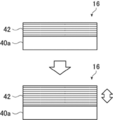
- FIG. 3 is a conceptual diagram for explaining the operation of an example of a bandpass filter used in the sensor of the present invention.
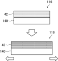
- the bandpass filter 16 shown in FIG. 3 has a bandpass layer 42 and a support 40a that supports the bandpass layer 42.
- the support 40a is an example in which the coefficient of thermal expansion ⁇ 2 of glass or the like is substantially 0.
- the coefficient of thermal expansion ⁇ 1 of the bandpass layer 42 is larger than the coefficient of thermal expansion ⁇ 2 of the support 40a.
- the dimensional change of the bandpass layer 42 is larger than the dimensional change of the support 40a when it is thermally expanded.
- the elastic modulus E1 of the bandpass layer 42 is smaller than the elastic modulus E2 of the support 40a.
- the support 40a is thicker than the bandpass layer 42, so that the elastic modulus E1 of the bandpass layer 42 is smaller than the elastic modulus E2 of the support 40a means that the support 40a is more rigid than the bandpass layer 42. Means that is high.
- the support 40a when the environmental temperature rises, the support 40a hardly expands because the coefficient of thermal expansion ⁇ 2 is substantially 0, but the bandpass layer 42 expands. At that time, since the support 40a has higher rigidity than the bandpass layer 42, the bandpass layer 42 is restrained by the support 40a in the plane direction (left-right direction in FIG. 3) and its elongation is suppressed. Therefore, the bandpass layer 42 extends in the thickness direction and changes from the state shown at the top of FIG. 3 to the state shown at the bottom.
- the passing wavelength of the bandpass layer 42 depends on the dimensions of the structure formed in the thickness direction. Therefore, when the bandpass layer 42 is extended in the thickness direction, the dimensions of the structure formed in the thickness direction are extended, and the passing wavelength is lengthened accordingly.
- the bandpass layer 42 is a cholesteric liquid crystal layer
- the spiral pitch of the cholesteric liquid crystal layer changes in the direction of lengthening.
- the selective reflection wavelength becomes long.
- the bandpass layer 42 is a dielectric multilayer film
- the bandpass layer 42 when the bandpass layer 42 is extended in the thickness direction, the high refractive index layer and the low refractive index layer of the dielectric multilayer film change in the thickening direction. .. As the thickness of each high-refractive index layer and low-refractive index layer increases, the passing wavelength (reflection wavelength or transmission wavelength) becomes longer.
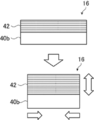
- FIG. 4 is a conceptual diagram for explaining the operation of another example of the bandpass filter used in the sensor of the present invention.
- the bandpass filter 16 shown in FIG. 4 has a bandpass layer 42 and a support 40b that supports the bandpass layer 42.
- the example shown in FIG. 4 is an example in which the support 40b uses a material having a negative coefficient of thermal expansion.
- the bandpass layer 42 expands. At that time, since the support 40b has higher rigidity than the bandpass layer 42, the bandpass layer 42 is restrained by the support 40b in the plane direction (left-right direction in FIG. 4), its elongation is suppressed, and it contracts. .. Therefore, the bandpass layer 42 extends in the thickness direction and changes from the state shown at the top of FIG. 4 to the state shown at the bottom. When the bandpass layer 42 is extended in the thickness direction, the dimensions of the structure formed in the thickness direction are extended, and the passing wavelength is lengthened accordingly.
- the amount of the bandpass layer 42 extending in the thickness direction becomes larger, so that the passing wavelength of the bandpass filter is further increased. It can be greatly changed.
- the thermal expansion coefficient ⁇ 2 of the support is larger than the thermal expansion coefficient ⁇ 1 of the bandpass layer
- the bandpass layer 42 also expands.
- the coefficient of thermal expansion ⁇ 1 of the bandpass layer 42 is smaller than the coefficient of thermal expansion ⁇ 2 of the support 140, the amount of the bandpass layer 42 extending in the plane direction is small, but the bandpass layer 42 is in the plane direction.
- the bandpass layer 42 Since it is restrained by the support 140, it is stretched in accordance with the elongation of the support 140. Therefore, the bandpass layer 42 hardly extends in the thickness direction, and changes from the state shown in the upper part of FIG. 5 to the state shown in the lower part. Since the bandpass layer 42 does not extend in the thickness direction, the passing wavelength of the bandpass layer 42 does not change.
- the bandpass layer hardly expands thermally, it does not extend in the thickness direction, and the passing wavelength of the bandpass layer does not change.
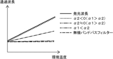
- FIG. 6 shows a graph conceptually showing the relationship between the environmental temperature and the passing wavelength of the bandpass filter.
- FIG. 6 also shows the relationship between the emission wavelength of the light source and the environmental temperature. As shown in FIG. 6, the emission wavelength of the light source becomes longer as the environmental temperature increases.
- the thermal expansion coefficient ⁇ 1 of the conventional inorganic bandpass filter and the bandpass layer is smaller than the thermal expansion coefficient ⁇ 2 of the support ( ⁇ 1 ⁇ 2), the bandpass filter can be used even if the environmental temperature rises. The passing wavelength does not change. Therefore, as shown in FIG.
- the bandpass increases as the environmental temperature increases.
- the passing wavelength of the filter becomes longer. Therefore, even in a narrow band bandpass filter, when the ambient temperature changes, the emission wavelength of the light source and the pass wavelength of the bandpass filter change in the same manner. Therefore, the light having the emission wavelength of the light source can pass through the bandpass filter, the amount of light incident on the light receiving element at the wavelength passing through the light source can be prevented from decreasing, and the SN ratio can be prevented from decreasing.
- the coefficient of thermal expansion of the support was set to approximately 0, and in the example shown in FIG. 4, the coefficient of thermal expansion of the support was negative, but the present invention is not limited to this, and the coefficient of thermal expansion of the support is not limited to this. May be a positive value. Even when the coefficient of thermal expansion of the support is positive, if the coefficient of thermal expansion ⁇ 1 of the bandpass layer is larger than the coefficient of thermal expansion ⁇ 2 of the support, the plane direction of the bandpass layer when the environmental temperature rises. The amount of extension to the surface is larger than the amount of extension of the support in the surface direction, but since the bandpass layer is constrained by the support in the surface direction, the amount of extension in the surface direction is suppressed. Therefore, the bandpass layer extends in the thickness direction.
- the coefficient of thermal expansion ⁇ 1 of the bandpass layer is preferably 20 to 200 ppm / ° C., preferably 30 to 150 ppm / ° C. from the viewpoint that the passing wavelength of the bandpass filter can be changed more preferably with respect to the change in the environmental temperature. °C is more preferable, and 40 to 100 ppm / ° C is even more preferable.
- the coefficient of thermal expansion ⁇ 2 of the support is preferably ⁇ 500 to 20 ppm / ° C., preferably ⁇ 300 to 10 ppm / ° C. °C is more preferable, and ⁇ 200 to 5 ppm / ° C is even more preferable. Further, it is also preferable that the coefficient of thermal expansion ⁇ 2 of the support is less than 0 mmp / ° C., that is, it has a coefficient of thermal expansion of negative.
- the difference between the thermal expansion coefficient ⁇ 1 of the bandpass layer and the thermal expansion coefficient ⁇ 2 of the support is 30 ppmm / from the viewpoint that the passing wavelength of the bandpass filter can be changed more preferably with respect to the change of the environmental temperature.
- the temperature is preferably °C or higher, more preferably 35 to 200 ppm / ° C, and even more preferably 40 to 200 ppm / °C.
- the coefficient of thermal expansion is measured as follows. For example, it can be measured by a known method such as JIS K 7197. For example, it is obtained by thermomechanical characteristic measurement using a thermomechanical analyzer (TMA4000SE manufactured by TMA NETZSCH).
- TMA4000SE manufactured by TMA NETZSCH
- the measurement conditions are, for example, that the sample size is 5 mm ⁇ 20 mm, the distance between chucks is 15 mm, the length of the chuck portion is 2.5 ⁇ 0.5 mm both above and below, and 5 ° C / min in the range of -20 ° C to 60 ° C. Change the temperature with, and measure the amount of displacement of the chuck distance at that time.
- the load is measured by applying a constant load of 3 g to the sample.
- the slope of the approximate straight line of the displacement data of ⁇ 20 ° C. to 60 ° C. is obtained, and the displacement amount per 1 ° C. change in temperature is obtained.
- the coefficient of thermal expansion can be calculated by dividing the inclination by the chunking distance of 15 mm at the time of sample setting.
- the elastic modulus E1 of the bandpass layer is preferably less than 10 GPa and preferably 1 to 8 GPa. More preferably, it is more preferably 2 to 6 GPa.
- the elastic modulus E2 of the support is preferably 10 to 200 GPa, preferably 20 to 150 GPa. Is more preferable, and 40 to 100 GPa is further preferable.
- the ratio of the elastic modulus E1 of the bandpass layer to the elastic modulus E2 of the support is 2 or more. It is preferably 5 or more, more preferably 10 or more, and even more preferably 10.
- the elastic modulus is measured as follows. Unless otherwise specified, the elastic modulus is the elastic modulus at room temperature (25 ° C.). The elastic modulus can be measured by a known method such as JIS K 7127.
- the half width of the peak of the passing wavelength of the bandpass filter is preferably 20 nm or less. That is, when the bandpass filter is a transmission type bandpass filter, the half width of the transmission peak of the bandpass layer is preferably 20 nm or less, more preferably 1 to 18 nm, and 2 to 15 nm. Is even more preferable. When the bandpass filter is a reflection type bandpass filter, the half width of the reflection peak of the bandpass layer is preferably 20 nm or less, more preferably 1 to 18 nm, and 2 to 15 nm. Is even more preferable.
- the external light incident on the sensor can be cut more preferably, and the SN ratio can be made higher.
- the passing wavelength of the bandpass filter changes according to the change of the environmental temperature, even if the half width of the bandpass filter is small, the emission wavelength and the band of the light source are changed when the environmental temperature changes. It is possible to suitably suppress the occurrence of deviation from the passing wavelength of the pass filter.
- the bandpass layer has a cholesteric liquid crystal layer which is a layer formed by fixing the cholesteric liquid crystal phase, and the cholesteric liquid crystal layer has an in-plane refractive index nx in the slow axis direction and a phase advance axis direction.
- the refractive index ny has a region satisfying nx> ny and the selective reflection center wavelength of the cholesteric liquid crystal layer is ⁇
- the cholesteric liquid crystal layer has a second selective reflection peak at a wavelength ⁇ / 2 and is ⁇ .
- the half-value width of the second selective reflection peak at / 2 is preferably 20 nm or less.
- the cholesteric liquid crystal layer has a region in which the in-plane refractive index nx in the slow axis direction and the refractive index ny in the phase advance axis direction satisfy nx> ny, whereby the cholesteric liquid crystal layer is selectively reflected. It is possible to have a configuration having a second selective reflection peak having a narrow half-value width at a wavelength halved of the center wavelength. By utilizing the second selective reflection peak having a narrow half-value width of the cholesteric liquid crystal layer, it is possible to obtain a narrow-band bandpass filter that allows only narrow-band light to pass through. By using such a bandpass filter, the sensor of the present invention can further reduce the influence of external light and enable more accurate measurement with a high SN ratio.
- a cholesteric liquid crystal layer having a region satisfying nx> ny and having a second selective reflection peak at a wavelength of ⁇ / 2 will be described.
- FIG. 7 conceptually shows an example of such a cholesteric liquid crystal layer.
- the cholesteric liquid crystal layer 26 shown in FIG. 7 is formed on the alignment film 24 formed on the support 20.
- the support 20 side is also referred to as the lower side, and the cholesteric liquid crystal layer 26 side is also referred to as the upper side. Therefore, in the support 20, the cholesteric liquid crystal layer 26 side is also referred to as an upper surface, and the opposite side is also referred to as a lower surface.
- the surface on the support 20 side is also referred to as a lower surface, and the surface on the opposite side is also referred to as an upper surface.
- the support 20 supports the cholesteric liquid crystal layer when forming the cholesteric liquid crystal layer 26.
- the support 20 and the alignment film 24 may be peeled off and transferred to the support of the bandpass filter for use. That is, the support 20 may be a temporary support.
- the support 20 may be used as a support for the bandpass filter. That is, the cholesteric liquid crystal layer 26 may be formed on the support of the bandpass filter.
- the support 20 When the support 20 is used as the support of the bandpass filter, the support described above may be used as the support 20. Further, when the support 20 is a temporary support, various temporary supports used when producing the cholesteric liquid crystal layer are exemplified.
- the temporary support include film-shaped members made of glass, triacetyl cellulose (TAC), polyethylene terephthalate (PET), polycarbonate, polyvinyl chloride, acrylic, polyolefin, and the like. Further, it may be a multi-layered support having a plurality of layers made of these materials.
- the alignment film 24 is formed on the surface (upper surface) of the support 20.
- the alignment film 24 is an alignment film for orienting the liquid crystal compound 32 in a predetermined orientation state when forming the cholesteric liquid crystal layer 26.
- a rubbing-treated film made of an organic compound such as a polymer, an oblique vapor deposition film of an inorganic compound, a film having a microgroove, and Langmuir of an organic compound such as ⁇ -tricosanoic acid, dioctadecylmethylammonium chloride and methyl stearylate examples thereof include a film obtained by accumulating an LB (Langmuir-Blodgett) film obtained by a Brodget method, a photoalignment film obtained by emitting polarized or non-polarized material from a photoalignable material to form an alignment film, and the like.
- the alignment film 24 may be formed by a known method according to the material for forming the alignment film.
- the alignment film by the rubbing treatment can be formed by rubbing the surface of the polymer layer with paper or cloth several times in a certain direction.
- Materials used for the alignment film include polyimide, polyvinyl alcohol, polymers having a polymerizable group described in JP-A-9-152509, JP-A-2005-97377, JP-A-2005-99228, and JP-A-2005-99228. Materials used for forming alignment films and the like described in JP-A-2005-128503 are preferable.
- the support 20 may act as the alignment film by subjecting the support 20 to a rubbing treatment, a laser processing, or the like without forming the alignment film 24.
- a so-called photo-alignment film which is obtained by irradiating a photo-alignable material with polarized light or non-polarized light to form the alignment film 24, is also preferably used. That is, as the alignment film 24, a photoalignment film formed by applying a photoalignment material on the support 20 is preferably used. Polarized light irradiation can be performed from a vertical direction or an oblique direction with respect to the light alignment film, and non-polarized light irradiation can be performed from an oblique direction with respect to the light alignment film.
- Examples of the photo-alignment material used for the alignment film that can be used in the present invention include JP-A-2006-285197, JP-A-2007-76839, JP-A-2007-138138, and JP-A-2007-94071. , JP-A-2007-121721, JP-A-2007-140465, JP-A-2007-156439, JP-A-2007-133184, JP-A-2009-109831, Patent No. 3883848 and Patent No. 4151746.
- the azo compound described in JP-A the aromatic ester compound described in JP-A-2002-229039, the maleimide having the photoorientation unit described in JP-A-2002-265541 and JP-A-2002-317013, and / Alternatively, an alkenyl-substituted nadiimide compound, a photobridgeable silane derivative described in Japanese Patent No. 4205195 and Patent No. 4205198, photocrossblinkability described in JP-A-2003-520878, JP-A-2004-522220 and Patent No. 4162850.
- Preferred examples thereof include photodimerizable compounds described in Japanese Patent Application Laid-Open No. 177561 and Japanese Patent Application Laid-Open No. 2014-012823, particularly a cinnamate compound, a chalcone compound, and a coumarin compound.
- an azo compound, a photocrosslinkable polyimide, a photocrosslinkable polyamide, a photocrosslinkable polyester, a cinnamate compound, and a chalcone compound are preferably used.
- the thickness of the alignment film 24 is not limited, and the thickness at which the required alignment function can be obtained may be appropriately set according to the material for forming the alignment film.
- the thickness of the alignment film is preferably 0.01 to 5 ⁇ m, more preferably 0.05 to 2 ⁇ m.
- the cholesteric liquid crystal layer 26 is formed on the surface of the alignment film 24.
- the cholesteric liquid crystal layer 26 is used for two rotations (720 ° rotation) of the twisting orientation of the liquid crystal compound 32 in the cholesteric liquid crystal phase. ) Only conceptually. That is, FIG. 7 shows only two pitches of the spiral structure in the cholesteric liquid crystal phase.
- the cholesteric liquid crystal layer 26 is a spiral in which the liquid crystal compound 32 spirally swirls and is stacked along a spiral axis in the thickness direction, similarly to the cholesteric liquid crystal layer formed by fixing a normal cholesteric liquid crystal phase.
- the cholesteric liquid crystal phase (cholesteric liquid crystal layer) is one in which spiral structures are laminated at one pitch or more.
- the cholesteric liquid crystal layer exhibits reflectivity having wavelength selectivity, which will be described later, by laminating spiral structures made of the liquid crystal compound 32 at one pitch or more. Therefore, in the present invention, even if the liquid crystal compound 32 has a spiral structure in which the liquid crystal compound 32 is spirally swirled and stacked along the spiral axis in the thickness direction, the layer having a spiral period of less than one pitch is a layer. , It is not a helix liquid crystal layer.
- the cholesteric liquid crystal layer 26 is formed by fixing the cholesteric liquid crystal phase. That is, the cholesteric liquid crystal layer 26 is a layer in which the liquid crystal compound 32 (liquid crystal material) is cholesterically oriented. As is well known, the cholesteric liquid crystal layer having a fixed cholesteric liquid crystal phase has wavelength selective reflectivity. As will be described in detail later, the selective reflection wavelength range of the cholesteric liquid crystal layer depends on the length of the spiral 1 pitch in the thickness direction (pitch P shown in FIG. 7).
- the first embodiment in the case where the bandpass layer has a cholesteric liquid crystal layer which is a layer formed by fixing the cholesteric liquid crystal phase is described in the first embodiment.
- the cholesteric liquid crystal layer has a region in which the in-plane refractive index nx in the slow-phase axial direction and the refractive index ny in the phase-advancing axial direction satisfy nx> ny.
- the selective reflection center wavelength of the cholesteric liquid crystal layer is ⁇
- the cholesteric liquid crystal layer has a second selective reflection peak at a wavelength of ⁇ / 2
- the half width of the second selective reflection peak at ⁇ / 2 is 20 nm or less.
- the second selective reflection peak at ⁇ / 2 is used as the bandpass.
- the second embodiment when the bandpass layer has a cholesteric liquid crystal layer which is a layer formed by immobilizing a cholesteric liquid crystal phase, the second embodiment is The half width of the selective reflection peak of the cholesteric liquid crystal layer is 45 nm or less. In this case, there is no second selective reflection peak, and the first selective reflection peak is used as a bandpass.
- the cholesteric liquid crystal layer 26 is in the in-plane slow phase axial direction.
- the refractive index nx and the refractive index ny in the phase-advancing axis direction satisfy nx> ny.
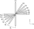
- the cholesteric liquid crystal layer 26 has a configuration in which the angle formed by the molecular axes of adjacent liquid crystal compounds 32 gradually changes when the arrangement of the liquid crystal compounds 32 is viewed from the spiral axis direction. ..
- the establishment of the existence of the liquid crystal compound 32 when the arrangement of the liquid crystal compound 32 is viewed from the spiral axis direction is different.
- the cholesteric liquid crystal layer 26 has a structure in which the in-plane refractive index nx in the slow axis direction and the refractive index ny in the phase advance axis direction satisfy nx> ny.
- the angle formed by the molecular axes of the adjacent liquid crystal compounds 32 gradually changes. Having such a configuration is also referred to as having a refractive index ellipsoid.
- the cholesteric liquid crystal layer 26 is configured such that the in-plane refractive index nx in the slow axis direction and the refractive index ny in the phase advance axis direction satisfy nx> ny, so that the reflection is reflected by the cholesteric liquid crystal layer 26.
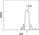
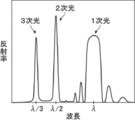
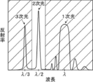
- primary light and secondary light are obtained.
- the secondary light is obtained as a wavelength having a very narrow band as compared with the primary light.
- the selective center reflection wavelength of the secondary light is half of the selective center reflection wavelength of the primary light.
- the operation of such a cholesteric liquid crystal layer 26 (bandpass filter) will be described in detail later.
- the primary light is light corresponding to the selective reflection peak (hereinafter, also referred to as the first selective reflection peak) of the selective reflection center wavelength of the cholesteric liquid crystal layer.
- the secondary light is the light corresponding to the second selective reflection peak.
- the cholesteric liquid crystal phase is known to exhibit selective reflectivity at specific wavelengths.
- the selective reflection center wavelength can be adjusted by adjusting this spiral pitch.
- the spiral pitch P is the spiral structure of the cholesteric liquid crystal phase for one pitch (the period of the spiral), in other words, the number of turns of the spiral is one, that is, it constitutes the cholesteric liquid crystal phase.
- This is the length in the spiral axis direction in which the director of the liquid crystal compound (in the case of a rod-shaped liquid crystal, in the long axis direction) rotates 360 °.
- the spiral period pitch is equal to the length of two bright lines and two dark lines in the thickness direction, that is, the lengths of two dark lines and two bright lines in the thickness direction.
- the spiral pitch of the cholesteric liquid crystal phase depends on the type of chiral agent used together with the liquid crystal compound and the concentration of the chiral agent added when forming the cholesteric liquid crystal layer. Therefore, by adjusting these, a desired spiral pitch can be obtained.
- pitch adjustment see Fujifilm Research Report No. 50 (2005) p. There is a detailed description in 60-63.
- For the measurement method of spiral sense and pitch use the method described in "Introduction to Liquid Crystal Chemistry Experiment", ed. be able to.
- the cholesteric liquid crystal phase exhibits selective reflectivity to either left or right circularly polarized light at a specific wavelength. Whether the reflected light is right-handed circularly polarized light or left-handed circularly polarized light depends on the twisting direction (sense) of the spiral of the cholesteric liquid crystal phase.
- the selective reflection of circularly polarized light by the cholesteric liquid crystal phase reflects the right circularly polarized light when the twisting direction of the spiral of the cholesteric liquid crystal layer is right, and reflects the left circularly polarized light when the twisting direction of the spiral is left.
- the twisting direction of the spiral in the cholesteric liquid crystal phase can be confirmed by incident right-handed circularly polarized light and / or left-handed circularly polarized light on the cholesteric liquid crystal layer.
- the direction of rotation of the cholesteric liquid crystal phase can be adjusted by the type of the liquid crystal compound forming the cholesteric liquid crystal layer and / or the type of the chiral agent added.
- the selective reflection center wavelength is not limited and may be appropriately set according to the application of the sensor using the bandpass filter. Specifically, in the cholesteric liquid crystal layer, the selective reflection center wavelength may be appropriately set according to the wavelength of the measurement light used by the sensor. As will be described later, in the present embodiment, the sensor receives light in the wavelength range of the second selective reflection peak of the bandpass filter by the light receiving element. The wavelength of the second selective reflection peak is 1/2 wavelength of the selective reflection center wavelength ⁇ of the cholesteric liquid crystal layer. Therefore, the selective reflection center wavelength of the cholesteric liquid crystal layer is set so that the wavelength of the second selective reflection peak is included in the wavelength range of the measurement light.
- the selective reflection center wavelength of the cholesteric liquid crystal layer depends on the pitch P of the spiral structure. Therefore, the pitch P of the spiral structure may be set so that the wavelength of the second selective reflection peak is included in the wavelength range of the measurement light.
- the pitch P of the spiral structure can be confirmed by observing the cross section of the cholesteric liquid crystal layer with SEM and analyzing the striped pattern having alternating bright lines and dark lines in the thickness direction derived from the cholesteric liquid crystal phase.
- the cholesteric liquid crystal layer can be formed by fixing the cholesteric liquid crystal phase in a layered manner.
- the structure in which the cholesteric liquid crystal phase is fixed may be any structure as long as the orientation of the liquid crystal compound which is the cholesteric liquid crystal phase is maintained. Therefore, it is preferable that the structure is polymerized and cured by irradiation with ultraviolet rays, heating, etc. to form a non-fluid layer, and at the same time, the structure is changed to a state in which the orientation form is not changed by an external field or an external force.
- the polymerizable liquid crystal compound may lose its liquid crystal property by increasing its molecular weight by a curing reaction.
- a liquid crystal composition containing a liquid crystal compound can be mentioned.
- the liquid crystal compound is preferably a polymerizable liquid crystal compound.
- the liquid crystal composition used for forming the cholesteric liquid crystal layer may further contain a surfactant and a chiral agent.
- the polymerizable liquid crystal compound may be a rod-shaped liquid crystal compound or a disk-shaped liquid crystal compound.
- Examples of the rod-shaped polymerizable liquid crystal compound forming the cholesteric liquid crystal phase include a rod-shaped nematic liquid crystal compound.
- rod-shaped nematic liquid crystal compound examples include azomethines, azoxys, cyanobiphenyls, cyanophenyl esters, benzoic acid esters, cyclohexanecarboxylic acid phenyl esters, cyanophenylcyclohexanes, cyano-substituted phenylpyrimidins, and alkoxy-substituted phenylpyrimidins.
- Phenyldioxans, trans, alkenylcyclohexylbenzonitriles and the like are preferably used. Not only low molecular weight liquid crystal compounds but also high molecular weight liquid crystal compounds can be used.
- the polymerizable liquid crystal compound is obtained by introducing a polymerizable group into the liquid crystal compound.
- the polymerizable group include an unsaturated polymerizable group, an epoxy group, and an aziridinyl group, and an unsaturated polymerizable group is preferable, and an ethylenically unsaturated polymerizable group is more preferable.
- the polymerizable group can be introduced into the molecule of the liquid crystal compound by various methods.
- the number of polymerizable groups contained in the polymerizable liquid crystal compound is preferably 1 to 6, more preferably 1 to 3.
- Examples of polymerizable liquid crystal compounds include Makromol. Chem. , 190, 2255 (1989), Advanced Materials 5, 107 (1993), US Pat. No.
- a cyclic organopolysiloxane compound having a cholesteric phase as disclosed in Japanese Patent Application Laid-Open No. 57-165480 can be used.
- a polymer liquid crystal compound a polymer having a mesogen group exhibiting liquid crystal introduced at the main chain, a side chain, or both the main chain and the side chain, and a polymer cholesteric having a cholesteryl group introduced into the side chain.
- a liquid crystal, a liquid crystal polymer as disclosed in JP-A-9-133810, a liquid crystal polymer as disclosed in JP-A-11-293252, and the like can be used.
- Disc-shaped liquid crystal compound for example, those described in JP-A-2007-108732 and JP-A-2010-244033 can be preferably used.
- the amount of the polymerizable liquid crystal compound added to the liquid crystal composition is preferably 75 to 99.9% by mass, preferably 80 to 99%, based on the solid content mass (mass excluding the solvent) of the liquid crystal composition. It is more preferably by mass, and even more preferably 85 to 90% by mass.
- the liquid crystal composition used for forming the cholesteric liquid crystal layer may contain a surfactant.
- the surfactant is preferably a compound that can function as an orientation control agent that contributes to the orientation of the cholesteric liquid crystal phase stably or rapidly.
- Examples of the surfactant include a silicone-based surfactant and a fluorine-based surfactant, and a fluorine-based surfactant is preferably exemplified.
- the surfactant include the compounds described in paragraphs [2002] to [0090] of JP-A-2014-119605, and the compounds described in paragraphs [0031]-[0034] of JP-A-2012-203237. , The compounds exemplified in paragraphs [0092] and [093] of JP-A-2005-09924, paragraphs [0076] to [0078] and paragraphs [0083] to [985] of JP-A-2002-129162. Examples thereof include the compounds exemplified in the above, and the fluorine (meth) acrylate-based polymers described in paragraphs [0018] to [0043] of JP-A-2007-272185.
- the surfactant one type may be used alone, or two or more types may be used in combination.
- the fluorine-based surfactant the compounds described in paragraphs [2002] to [0090] of JP-A-2014-119605 are preferable.
- the amount of the surfactant added to the liquid crystal composition is preferably 0.01 to 10% by mass, more preferably 0.01 to 5% by mass, and 0.02 to 1% by mass with respect to the total mass of the liquid crystal compound. Is even more preferable.
- the liquid crystal compound in the second embodiment when the bandpass layer has a cholesteric liquid crystal layer which is a layer formed by fixing the cholesteric liquid crystal phase, ⁇ n is small and the selective reflection of the cholesteric liquid crystal layer.
- the liquid crystal compound represented by the following formula (I) is preferable in that the half price range of is narrow.
- a liquid crystal compound satisfying mc> 0.1 is obtained by dividing the number of trans-1,4-cyclohexylene groups which may have a substituent represented by A by m to mc. It is preferable that the liquid crystal compound satisfies 0.4 ⁇ mc ⁇ 0.8.
- Q 1 and Q 2 each independently represent a hydrogen atom, or represents a polymerizable group selected from the group consisting of groups represented by the following formulas (Q-1) ⁇ formula (Q-5), provided that Either Q 1 or Q 2 shows a polymerizable group;
- A is a phenylene group which may have a substituent or a trans-1,4-cyclohexylene group which may have a substituent.
- the phenylene group is preferably a 1,4-phenylene group.
- At least one of A is a trans-1,4-cyclohexylene group which may have a substituent.
- the m A's may be the same or different from each other.
- M indicates an integer of 3 to 12, preferably an integer of 3 to 9, more preferably an integer of 3 to 7, and even more preferably an integer of 3 to 5.
- the phenylene group and the trans-1,4-cyclohexylene group may have 1 to 4 substituents. When having two or more substituents, the two or more substituents may be the same or different from each other.
- the alkyl group may be either linear or branched.
- the number of carbon atoms of the alkyl group is preferably 1 to 30, more preferably 1 to 10, and even more preferably 1 to 6.
- Examples of the alkyl group include a methyl group, an ethyl group, an n-propyl group, an isopropyl group, an n-butyl group, an isobutyl group, a sec-butyl group, a tert-butyl group, an n-pentyl group, an isopentyl group and a neopentyl group.
- Examples thereof include 1,1-dimethylpropyl group, n-hexyl group, isohexyl group, heptyl group, octyl group, nonyl group, decyl group, undecyl group, dodecyl group and the like.
- the description of the alkyl group in the alkoxy group is the same as the description of the above alkyl group.
- specific examples of the alkylene group when referred to as an alkylene group include a divalent group obtained by removing one arbitrary hydrogen atom in each of the above-mentioned examples of an alkyl group.
- Examples of the halogen atom include a fluorine atom, a chlorine atom, a bromine atom, and an iodine atom.
- the number of carbon atoms of the cycloalkyl group is preferably 3 or more, more preferably 5 or more, preferably 20 or less, more preferably 10 or less, further preferably 8 or less, and particularly preferably 6 or less.
- the cycloalkyl group include a cyclopropyl group, a cyclobutyl group, a cyclopentyl group, a cyclohexyl group, a cycloheptyl group, a cyclooctyl group and the like.
- X 3 represents a single bond, -O-, -S-, or -N (Sp 4- Q 4 )-, or a nitrogen atom forming a ring structure with Q 3 and Sp 3. show.
- Sp 3 and Sp 4 are independently one or two in a single bond or a linear or branched alkylene group having 1 to 20 carbon atoms and a linear or branched alkylene group having 1 to 20 carbon atoms.
- the linking group selected from the group consisting of the group substituted with O- is shown.
- the m L's may be the same or different from each other.
- Sp 1 and Sp 2 are independently one or two in a single bond or a linear or branched alkylene group having 1 to 20 carbon atoms and a linear or branched alkylene group having 1 to 20 carbon atoms.
- Q 1 and Q 2 each independently represent a hydrogen atom or a polymerizable group selected from the group consisting of groups represented by the following formulas (Q-1) to (Q-5). However, either Q 1 or Q 2 shows a polymerizable group.
- an acryloyl group (formula (Q-1)) or a methacryloyl group (formula (Q-2)) is preferable.
- liquid crystal compound examples include a liquid crystal compound represented by the following formula (I-11), a liquid crystal compound represented by the formula (I-21), and a liquid crystal compound represented by the formula (I-31). Can be mentioned.
- Liquid crystal compound represented by the formula (I-11) Liquid crystal compound represented by the formula (I-11)
- R 11 represents a hydrogen atom, a linear or branched alkyl group having 1 to 12 carbon atoms, or -Z 12- Sp 12- Q 12 .
- R 2 represents a hydrogen atom or an alkyl group having 1 to 3 carbon atoms.
- a polymerizable group selected from Q 12 represents a polymerizable group selected from the group consisting of groups represented by hydrogen atom or formula (Q-1) ⁇ formula (Q-5), l 11 indicates an integer from 0 to 2 and represents m 11 indicates an integer of 1 or 2 and represents n 11 indicates an integer from 1 to 3 and represents A plurality of R 11, a plurality of L 11, a plurality of L 12, a plurality of l 11, a plurality of Z 11, a plurality of Sp 11, and a plurality of Q 11 may each be the same or different from each other.
- the liquid crystal compound represented by the formula (I-11) is polymerizable as R 11 selected from the group consisting of groups in which Q 12 is represented by the formulas (Q-1) to (Q-5). It contains at least one of the basis -Z 12- Sp 12- Q 12.
- the 1,4-cyclohexylene group contained in the liquid crystal compound represented by the formula (I-11) is a trans-1,4-cyclohexylene group.
- L 11 is a single bond
- l 11 is 1 (dicyclohexyl group)
- Q 11 is a formula (Q-1) to a formula (Q-5).
- liquid crystal compound represented by formula (I-11) m 11 is 2, l 11 is 0, and also the two R 11 are both represent -Z 12 -Sp 12 -Q 12 , Q 12 and the like are compounds which are polymerizable groups selected from the group consisting of groups represented by the formula (Q-1) ⁇ formula (Q-5).
- Liquid crystal compound represented by the formula (I-21) Liquid crystal compound represented by the formula (I-21)
- Z 21 and Z 22 each independently represent a trans-1,4-cyclohexylene group which may have a substituent or a phenylene group which may have a substituent.
- Each of the above substituents is 1 to 4 substituents independently selected from the group consisting of -CO-X 21- Sp 23- Q 23, an alkyl group, and an alkoxy group.
- m21 represents an integer of 1 or 2
- n21 represents an integer of 0 or 1. When m21 indicates 2, n21 indicates 0, When m21 indicates 2, the two Z 21s may be the same or different.
- At least one of Z 21 and Z 22 is a phenylene group which may have a substituent.
- X 21 indicates -O-, -S-, or -N (Sp 25- Q 25 )-or indicates a nitrogen atom that forms a ring structure with Q 23 and Sp 23.
- r 21 represents an integer from 1 to 4 Sp 21 , Sp 22 , Sp 23 , and Sp 25 are independently single-bonded or linear or branched alkylene groups with 1 to 20 carbon atoms and linear or branched alkylene groups with 1 to 20 carbon atoms.
- Each Q 21 and Q 22 independently represents either a polymerizable group selected from the group consisting of groups represented by the formula (Q-1) ⁇ formula (Q-5),
- a single bond is exhibited when any of the polymerizable groups to be used, or X 21, is a nitrogen atom forming a ring structure together with Q 23 and Sp 23.
- Sp 25 is a single bond, indicating any polymerizable group selected from the group
- Q 25 is not a hydrogen atom.
- the liquid crystal compound represented by the formula (I-21) preferably has a structure in which 1,4-phenylene groups and trans-1,4-cyclohexylene groups are alternately present, for example, m21 is 2.
- n21 is 0, and, if Z 21 are each optionally substituted trans-1,4-cyclohexylene group, an arylene group optionally having a substituent from Q 21 side, Alternatively, m21 is 1, n21 is 1, Z 21 is an arylene group which may have a substituent, and Z 22 is an arylene group which may have a substituent. Is preferable.
- Liquid crystal compound represented by the formula (I-31) Liquid crystal compound represented by the formula (I-31);
- n31 and n32 independently represent integers from 0 to 4, respectively.
- X 31 indicates a single bond, -O-, -S-, or -N (Sp 34- Q 34 )-or indicates a nitrogen atom forming a ring structure with Q 33 and Sp 33.
- Z 31 represents a phenylene group which may have a substituent and represents Z 32 represents a trans-1,4-cyclohexylene group which may have a substituent or a phenylene group which may have a substituent.
- m31 indicates an integer of 1 or 2
- m32 indicates an integer of 0 to 2.
- Q 31 and Q 32 each independently represent any polymerizable group selected from the group consisting of the groups represented by the formulas (Q-1) to (Q-5).
- Q 33 and Q 34 one or more of -CH 2- is -O-, -S-, -NH-, and -N (CH 3) independently of hydrogen atom, cycloalkyl group, and cycloalkyl group.
- Q 33 may exhibit a single bond when forming a ring structure with X 31 and Sp 33, with Sp 34 In the case of a single bond, Q 34 is not a hydrogen atom.
- particularly preferable compounds include a compound in which Z 32 is a phenylene group and a compound in which m 32 is 0.
- the compound represented by the formula (I) has a partial structure represented by the following formula (II).
- the black circle indicates the bonding position with the other part of the formula (I).
- the partial structure represented by the formula (II) may be included as a part of the partial structure represented by the following formula (III) in the formula (I).
- X 3 represents a single bond, -O-, -S-, or -N (Sp 4- Q 4 )-, or a nitrogen atom forming a ring structure with Q 3 and Sp 3. show.
- X 3 is preferably single bond or O-.
- the bonding position of R 1 and R 2 to each phenylene group is not particularly limited.
- Sp 3 and Sp 4 are independently one or two in a single bond or a linear or branched alkylene group having 1 to 20 carbon atoms and a linear or branched alkylene group having 1 to 20 carbon atoms.
- a linear or branched alkylene group having 1 to 10 carbon atoms is preferable, a linear alkylene group having 1 to 5 carbon atoms is more preferable, and a direct chain having 1 to 3 carbon atoms is preferable.
- the alkylene group of the chain is more preferred.
- Q 3 and Q 4 independently have one or more -CH 2- in a hydrogen atom, a cycloalkyl group, and a cycloalkyl group-O-, -S-, -NH-, -N (CH 3).
- the compound represented by the formula (I) has a structure represented by the following formula (II-2), for example.
- Q 1 , Q 2 , Sp 1 and Sp 2 are synonymous with the definitions of each group in the above formula (I).
- the definitions of X 3 , Sp 3 , Q 3 , R 1 and R 2 are synonymous with the definitions of each group in the above formula (II).
- liquid crystal compound represented by the formula (I) and satisfying 0.4 ⁇ mc ⁇ 0.8 are as follows.
- Two or more liquid crystal compounds may be used in combination.
- two or more liquid crystal compounds represented by the formula (I) may be used in combination.
- the liquid crystal compound represented by the above formula (I) which is a liquid crystal compound represented by the formula (I) together with the liquid crystal compound satisfying 0.4 ⁇ mc ⁇ 0.8, is 0.1. It is preferable to use a liquid crystal compound satisfying ⁇ mc ⁇ 0.3.
- liquid crystal compound represented by the formula (I), which satisfies 0.1 ⁇ mc ⁇ 0.3 are as follows.
- the chiral agent has a function of inducing a helical structure of a cholesteric liquid crystal phase. Since the chiral agent has a different twisting direction or spiral period pitch of the spiral induced by the compound, it may be selected according to the purpose.
- chiral agents There are no restrictions on chiral agents, and known compounds (for example, Liquid Crystal Device Handbook, Chapter 3, Section 4-3, TN (twisted nematic), STN (Super Twisted Nematic) chiral agents, p. 199, Japan Society for the Promotion of Science, No. 1 142 Committee ed., 1989), isosorbide, isomannide derivatives and the like can be used.
- the chiral agent generally contains an asymmetric carbon atom, but an axial asymmetric compound or a surface asymmetric compound that does not contain an asymmetric carbon atom can also be used as the chiral agent.
- axial or asymmetric compounds include binaphthyl, helicene, paracyclophane, and derivatives thereof.
- the chiral agent may have a polymerizable group. When both the chiral agent and the liquid crystal compound have a polymerizable group, the repeating unit derived from the polymerizable liquid crystal compound and the repeating unit derived from the chiral agent are derived by the polymerization reaction between the polymerizable chiral agent and the polymerizable liquid crystal compound. Polymers with repeating units can be formed.
- the polymerizable group of the polymerizable chiral agent is preferably a group of the same type as the polymerizable group of the polymerizable liquid crystal compound. Therefore, the polymerizable group of the chiral agent is preferably an unsaturated polymerizable group, an epoxy group or an aziridinyl group, more preferably an unsaturated polymerizable group, and preferably an ethylenically unsaturated polymerizable group. More preferred. Moreover, the chiral agent may be a liquid crystal compound.
- the chiral auxiliary has a photoisomerizing group
- a pattern of a desired reflection wavelength corresponding to the emission wavelength can be formed by emitting a photomask such as an active ray after coating and orientation.
- a photomask such as an active ray after coating and orientation.
- an isomerization site of a compound exhibiting photochromic properties, an azo group, an azoxy group, or a cinnamoyl group is preferable.
- Specific compounds include JP-A-2002-08478, JP-A-2002-08851, JP-A-2002-179668, JP-A-2002-179669, JP-A-2002-179670, and JP-A-2002.
- the content of the chiral agent in the liquid crystal composition is preferably 0.01 to 200 mol%, more preferably 1 to 30 mol% with respect to the molar content of the liquid crystal compound.
- the liquid crystal composition contains a polymerizable compound, it preferably contains a polymerization initiator.
- the polymerization initiator used is preferably a photopolymerization initiator capable of initiating the polymerization reaction by emitting ultraviolet rays.
- photopolymerization initiators include ⁇ -carbonyl compounds (described in US Pat. No. 2,376,661 and US Pat. No. 2,376,670), acidoin ethers (described in US Pat. No. 2,448,828), and ⁇ -hydrogen. Substituent aromatic acidoine compound (described in US Pat. No.
- the polymerization initiator is preferably a dichroic radical polymerization initiator.
- the dichroic radical polymerization initiator is a photopolymerization initiator that has absorption selectivity for light in a specific polarization direction and is excited by the polarization to generate free radicals. That is, the dichroic radical polymerization initiator is a polymerization initiator having different absorption selectivity between light in a specific polarization direction and light in a polarization direction orthogonal to the light in the specific polarization direction. Details and specific examples thereof are described in the WO2003 / 054111 pamphlet. Specific examples of the dichroic radical polymerization initiator include a polymerization initiator having the following chemical formula. Further, as the dichroic radical polymerization initiator, the polymerization initiator described in paragraphs [0046] to [097] of JP-A-2016-535863 can be used.
- the content of the photopolymerization initiator in the liquid crystal composition is preferably 0.1 to 20% by mass, more preferably 0.5 to 12% by mass with respect to the content of the liquid crystal compound.
- the liquid crystal composition may optionally contain a cross-linking agent in order to improve the film strength and durability after curing.
- a cross-linking agent those that are cured by ultraviolet rays, heat, moisture and the like can be preferably used.
- the cross-linking agent is not particularly limited and may be appropriately selected depending on the intended purpose. For example, a polyfunctional acrylate compound such as trimethylolpropane tri (meth) acrylate and pentaerythritol tri (meth) acrylate; glycidyl (meth) acrylate.
- epoxy compounds such as ethylene glycol diglycidyl ether; aziridine compounds such as 2,2-bishydroxymethylbutanol-tris [3- (1-aziridinyl) propionate] and 4,4-bis (ethyleneiminocarbonylamino) diphenylmethane; hexa Isocyanate compounds such as methylenediisocyanate and biuret-type isocyanate; polyoxazoline compounds having an oxazoline group in the side chain; and alkoxysilane compounds such as vinyltrimethoxysilane and N- (2-aminoethyl) 3-aminopropyltrimethoxysilane. Can be mentioned.
- a known catalyst can be used depending on the reactivity of the cross-linking agent, and the productivity can be improved in addition to the improvement of the film strength and the durability. These may be used alone or in combination of two or more.
- the content of the cross-linking agent is preferably 3 to 20% by mass, more preferably 5 to 15% by mass, based on the solid content mass of the liquid crystal composition. When the content of the cross-linking agent is within the above range, the effect of improving the cross-linking density can be easily obtained, and the stability of the cholesteric liquid crystal phase is further improved.
- a polymerization inhibitor an antioxidant, an ultraviolet absorber, a light stabilizer, a coloring material, metal oxide fine particles, etc. are added to the liquid crystal composition within a range that does not deteriorate the optical performance and the like. Can be added with.
- the liquid crystal composition is preferably used as a liquid when forming the cholesteric liquid crystal layer.
- the liquid crystal composition may contain a solvent.
- the solvent is not limited and may be appropriately selected depending on the intended purpose, but an organic solvent is preferable.
- the organic solvent is not limited and may be appropriately selected depending on the intended purpose.
- the liquid crystal composition When forming the cholesteric liquid crystal layer, the liquid crystal composition is applied to the forming surface of the cholesteric liquid crystal layer, the liquid crystal compound is oriented in the state of the cholesteric liquid crystal phase, and then the liquid crystal compound is cured to form the cholesteric liquid crystal layer.
- the liquid crystal composition is applied to the alignment film 24 to orient the liquid crystal compound in the state of the cholesteric liquid crystal phase, and then the liquid crystal compound is cured. It is preferable to form the cholesteric liquid crystal layer 26 in which the cholesteric liquid crystal phase is fixed.
- printing methods such as inkjet and scroll printing, and known methods such as spin coating, bar coating and spray coating that can uniformly apply the liquid to a sheet-like material can be used.
- the applied liquid crystal composition is dried and / or heated as needed and then cured to form a cholesteric liquid crystal layer.
- the liquid crystal compound in the liquid crystal composition may be oriented to the cholesteric liquid crystal phase.
- the heating temperature is preferably 200 ° C. or lower, more preferably 130 ° C. or lower.
- the oriented liquid crystal compound is further polymerized, if necessary.
- the polymerization may be either thermal polymerization or photopolymerization by light emission, but photopolymerization is preferable. It is preferable to use ultraviolet rays for light emission. Emitted energy is preferably 20mJ / cm 2 ⁇ 50J / cm 2, more preferably 50 ⁇ 1500mJ / cm 2. In order to promote the photopolymerization reaction, light emission may be carried out under heating conditions or a nitrogen atmosphere. The wavelength of the emitted ultraviolet rays is preferably 250 to 430 nm.
- the thickness of the cholesteric liquid crystal layer there is no limit to the thickness of the cholesteric liquid crystal layer, and the required light reflectance depends on the application of the bandpass filter, the light reflectance required for the cholesteric liquid crystal layer, the material for forming the cholesteric liquid crystal layer, and the like.
- the thickness at which the above can be obtained may be appropriately set.
- a liquid crystal elastomer may be used for the cholesteric liquid crystal layer.
- the liquid crystal elastomer is a hybrid material of liquid crystal and elastomer.
- it has a structure in which a liquid crystal rigid mesogen group is introduced into a flexible polymer network having rubber elasticity. Therefore, it has a characteristic of having flexible mechanical properties and elasticity. Further, since the alignment state of the liquid crystal and the macroscopic shape of the system are strongly correlated, when the alignment state of the liquid crystal changes due to temperature, electric field, or the like, there is a feature that the macro deformation is performed according to the change in the degree of orientation.
- the sample shrinks in one direction of the director, and the amount of shrinkage increases with the temperature rise, that is, the degree of orientation of the liquid crystal. It will increase as it decreases.
- the deformation is thermoreversible and returns to its original shape when the temperature drops to the nematic phase again.
- the liquid crystal elastomer of the cholesteric liquid crystal phase when the temperature rises and the degree of orientation of the liquid crystal decreases, macroscopic elongation deformation in the spiral axis direction occurs, so that the spiral pitch length increases and the reflection center wavelength of the selective reflection peak becomes long. Shift to the wavelength side. This change is also thermally reversible, and the temperature drops and the reflection center wavelength returns to the short wavelength side.
- the cholesteric liquid crystal layer 26 is a refractive index ellipsoid having a structure in which the angle formed by the molecular axes of the adjacent liquid crystal compounds 32 gradually changes when the arrangement of the liquid crystal compounds 32 is viewed from the spiral axis direction.
- the refractive index ellipsoid will be described with reference to FIGS. 9 and 10.
- FIG. 9 is a view of a part (1/4 pitch) of a plurality of liquid crystal compounds twisted and oriented along the spiral axis from the spiral axis direction (y direction)
- FIG. 10 is a view from the spiral axis direction. It is a figure which shows conceptually the existence probability of the liquid crystal compound seen.
- the liquid crystal compound whose molecular axis is parallel to the y direction is C1
- the liquid crystal compound whose molecular axis is parallel to the x direction is C7
- the liquid crystal compound between C1 and C7 is the liquid crystal compound C7 from the liquid crystal compound C1 side. C2 to C6 toward the side.
- the liquid crystal compounds C1 to C7 are twisted and oriented along the spiral axis, and rotate 90 ° between the liquid crystal compounds C1 and the liquid crystal compound C7.
- the spiral axial direction from the liquid crystal compound C1 to the liquid crystal compound C7 (FIG. 9).
- the length is 1/4 pitch.
- the angles formed by the molecular axes of the adjacent liquid crystal compounds when viewed from the z direction (spiral axis direction) are different.
- the angle ⁇ 1 formed by the liquid crystal compound C1 and the liquid crystal compound C2 is larger than the angle ⁇ 2 formed by the liquid crystal compound C2 and the liquid crystal compound C3, and the angle formed by the liquid crystal compound C2 and the liquid crystal compound C3.
- theta 2 is larger than the angle theta 3 of a liquid crystal compound C3 and a liquid crystal compound C4, the angle theta 3 of a liquid crystal compound C3 and a liquid crystal compound C4, from the angle theta 4 between the liquid crystal compound C4 and the liquid crystal compound C5
- the angle ⁇ 4 formed by the liquid crystal compound C4 and the liquid crystal compound C5 is larger than the angle ⁇ 5 formed by the liquid crystal compound C5 and the liquid crystal compound C6, and the angle ⁇ 5 formed by the liquid crystal compound C5 and the liquid crystal compound C6 is large.
- the angle theta 6 of a liquid crystal compound C6 and a liquid crystal compound C7 is smallest.
- the liquid crystal compounds C1 to C7 are twisted and oriented so that the angle formed by the molecular axes of the adjacent liquid crystal compounds decreases from the liquid crystal compound C1 side toward the liquid crystal compound C7 side.
- the distance between the liquid crystal compounds distance in the thickness direction
- the configuration in which the rotation angle per unit length changes is repeated in the 1/4 pitch, and the liquid crystal compound is twisted and oriented.
- the rotation angle per unit length is constant, so that the angle formed by the molecular axes of the adjacent liquid crystal compounds is constant, so that the existence probability of the liquid crystal compound seen from the spiral axis direction is the same in any direction. Become.
- the angle of rotation per unit length decreases from the liquid crystal compound C1 side to the liquid crystal compound C7 side in the 1/4 pitch from the liquid crystal compound C1 to the liquid crystal compound C7.
- the existence probability of the liquid crystal compound seen from the spiral axis direction is higher in the x direction than in the y direction, as conceptually shown in FIG.
- the refractive index is different in the x-direction and the y-direction, and the refractive index anisotropy occurs.
- refractive index anisotropy occurs in the plane perpendicular to the spiral axis.
- the refractive index nx in the x direction, in which the probability of existence of the liquid crystal compound is high, is higher than the refractive index ny in the y direction, in which the probability of existence of the liquid crystal compound is low. Therefore, the refractive index nx and the refractive index ny satisfy nx> ny.
- the x direction in which the presence probability of the liquid crystal compound is high is the slow phase axis direction in the plane of the cholesteric liquid crystal layer 26, and the y direction in which the presence probability of the liquid crystal compound is low is the phase advance axis direction in the plane of the cholesteric liquid crystal layer 26.
- the composition in which the rotation angle per unit length changes within a 1/4 pitch (the configuration having a refractive index ellipsoid) is coated with a composition that becomes a cholesteric liquid crystal layer. Later, it can be formed by irradiating the cholesteric liquid crystal phase (composition layer) with polarized light in a direction orthogonal to the spiral axis.
- the cholesteric liquid crystal phase can be distorted to generate in-plane retardation. That is, the refractive index can be nx> the refractive index ny.
- the polymerization of the liquid crystal compound having a molecular axis in the direction matching the polarization direction of the irradiated polarized light proceeds.
- the chiral agent existing at this position is excluded and moves to another position. Therefore, at a position where the direction of the molecular axis of the liquid crystal compound is close to the polarization direction, the amount of the chiral auxiliary is small and the rotation angle of the torsional orientation is small.
- the refractive index nx and the refractive index ny of the optical element 10 can satisfy nx> ny. That is, the cholesteric liquid crystal layer can have a refractive index ellipsoid.
- This polarized light irradiation may be performed at the same time as the fixation of the cholesteric liquid crystal phase, the polarized light irradiation may be performed first, and then the non-polarized light irradiation may be further fixed, or the non-polarized light irradiation may be performed first and then fixed.
- Light orientation may be performed by polarized light irradiation. In order to obtain a large retardation, it is preferable to irradiate only polarized light or to irradiate polarized light first.
- Polarized irradiation is preferably performed in an inert gas atmosphere having an oxygen concentration of 0.5% or less.
- the irradiation energy is preferably 20 mJ / cm 2 to 10 J / cm 2 , and more preferably 100 to 800 mJ / cm 2 .
- the illuminance is preferably 20 ⁇ 1000mW / cm 2, more preferably more preferably from 50 ⁇ 500mW / cm 2, a 100 ⁇ 350mW / cm 2.
- the type of the liquid crystal compound that is cured by polarized light irradiation is not particularly limited, but a liquid crystal compound having an ethylene unsaturated group as a reactive group is preferable.
- a method using a dichroic liquid crystal polymerization initiator (WO03 / 054111A1) or light such as a cinnamoyl group in the molecule is used.
- Examples thereof include a method using a rod-shaped liquid crystal compound having an orientation functional group (Japanese Patent Laid-Open No. 2002-006138).
- the light to be irradiated may be ultraviolet light, visible light, or infrared light. That is, the light on which the liquid crystal compound can be polymerized may be appropriately selected according to the liquid crystal compound contained in the coating film, the polymerization initiator and the like.
- the polymerization of a liquid crystal compound having a molecular axis in a direction matching the polarization direction when the composition layer is irradiated with polarized light is more preferably promoted. Can be done.
- the direction of the slow phase axis, the direction of the phase advance axis, the refractive index nx, and the refractive index ny in the plane are determined by J. A. It can be measured using M-2000UI manufactured by Woollam.
- the refractive index nx and the refractive index ny can be obtained from the measured values of the phase difference ⁇ n ⁇ d by using the average birefringence n ave and the measured values of the thickness d.
- the selective reflection wavelength when measuring the direction of the slow axis in the plane of the cholesteric liquid crystal layer used in the present invention, the direction of the phase advance axis, the refractive index nx, and the refractive index ny, the selective reflection wavelength (in the case of the present invention). Is a wavelength larger than the selective reflection wavelength of the primary light (for example, a wavelength 100 nm larger than the end of the selective wavelength on the long wave side) as the measurement wavelength. By doing so, the influence of the optical rotation component of the retardation derived from the cholesteric selective reflection can be reduced as much as possible, so that accurate measurement can be performed.
- the cholesteric liquid crystal layer having a refractive index ellipse is cholesteric after the composition to be the cholesteric liquid crystal layer is applied, after the cholesteric liquid crystal phase is immobilized, or in a state where the cholesteric liquid crystal phase is semi-fixed. It can also be formed by stretching the liquid crystal layer.
- the cholesteric liquid crystal layer having a refractive index ellipsoid is formed by stretching, it may be uniaxially stretched or biaxially stretched.
- the stretching conditions may be appropriately set according to the material, thickness, desired refractive index nx, refractive index ny, etc. of the cholesteric liquid crystal layer.
- the stretching ratio is preferably 1.1 to 4.
- the ratio of the stretching ratio in one stretching direction to the stretching ratio in the other stretching direction is preferably 1.1 to 2.
- the secondary light is reflected in addition to the primary light.
- the center wavelength of the secondary light is approximately half the length of the selective reflection center wavelength ⁇ of the primary light.
- the bandwidth (half width) of the reflected secondary light is smaller than the bandwidth of the reflected primary light.
- the primary light is circularly polarized light of either right-handed circularly polarized light or left-handed circularly polarized light depending on the swirling direction of the cholesteric liquid crystal phase, while the secondary light is a component of either right-handed circularly polarized light or left-handed circularly polarized light. Also includes.
- FIG. 11 conceptually shows the reflection characteristics of a general cholesteric liquid crystal layer having no refractive index ellipsoid.
- 11 and 12 which will be described later, are graphs conceptually showing the reflection characteristics with the horizontal axis as the wavelength and the vertical axis as the reflectance.
- a general cholesteric liquid crystal layer has wavelength selectivity for reflection, and as shown in FIG. 11, reflects light in a wavelength range around the selective reflection center wavelength ⁇ with high reflectance almost uniformly.
- the reflected light having the selective reflection peak in the wavelength region including the selective reflection center wavelength ⁇ is the primary light.
- the reflectance for light in a wavelength range other than the periphery of the selective reflection center wavelength ⁇ is low.
- the cholesteric liquid crystal layer having a refractive index elliptical body has a wavelength region around the wavelength ⁇ / 2 in addition to light in the wavelength region around the selective reflection center wavelength ⁇ (primary light). Reflects light (secondary light) with a high refractive index.
- the half-value width of the second selective reflection peak at the wavelength ⁇ / 2 is narrower than the half-value width of the first selective reflection peak at the wavelength ⁇ , and is 30 nm or less.
- the measurement light reflected by the object O is reflected by the bandpass filter and incident on the light receiving element.
- the light incident on the light receiving element can be limited to the narrow band light reflected by the bandpass filter. Therefore, since the external light component reflected by the bandpass filter can be reduced and only a predetermined narrow band light can be incident on the light receiving element 14, noise due to external light can be significantly reduced, and the SN ratio is high and high accuracy. Can make various measurements.
- the light source is the wavelength ⁇ / 2.
- a light source that irradiates light may be used.
- the cholesteric liquid crystal layer 26 having a refractive index ellipse has light in the wavelength range around the selective reflection center wavelength ⁇ (primary light) and the wavelength range around the wavelength ⁇ / 2.
- light in the wavelength range around the wavelength ⁇ / 3 (third light) is also reflected with high reflectance.
- the half-value width of the tertiary light is also narrower than the half-value width of the primary light, and is 30 nm or less. Therefore, the sensor 10 may utilize the third selective reflection peak appearing at the wavelength ⁇ / 3 of the cholesteric liquid crystal layer 26.
- the light source irradiates the measurement light of the wavelength ⁇ / 3, and the measurement light of the wavelength ⁇ / 3 reflected by the object O is reflected by the bandpass filter (cholesteric liquid crystal layer 26) to receive the light receiving element. It may be configured to be incident on.
- the cholesteric liquid crystal layer 26 having a refractive index ellipsoid has higher-order selective reflection peaks such as a fourth selective reflection peak appearing at wavelength ⁇ / 4 and a fifth selective reflection peak appearing at wavelength ⁇ / 5. Therefore, the sensor may utilize the higher-order selective reflection peak of the cholesteric liquid crystal layer 26.
- the reflectance at the selective reflection peak decreases as the order increases, it is preferable to use the second selective reflection peak or the third selective reflection peak, and it is more preferable to use the second selective reflection peak.
- the thickness of the cholesteric liquid crystal layer 26 of the bandpass filter may be appropriately set according to the selective reflection wavelength range of the bandpass filter, the reflectance required for the bandpass filter, and the like.
- the bandpass filter is not limited to the wavelength range of the second selective reflection peak of the cholesteric liquid crystal layer. It reflects light in the selective reflection wavelength range (wavelength range of the first selective reflection peak) and light in the wavelength range of the third selective reflection peak. Therefore, when light in the selective reflection wavelength range and the wavelength range of the third selective reflection peak is incident on the bandpass filter, it is reflected by the bandpass filter and measured by the light receiving element, resulting in noise and a decrease in the SN ratio. do.
- light shielding that shields the wavelength range of the wavelength ⁇ -100 nm or more of the first selective reflection peak of the bandpass filter is shielded. It is preferable to provide at least one of the member and a light-shielding member that shields the wavelength region of the wavelength ⁇ / 2-50 nm or less of the second selective reflection peak, and it is more preferable to provide both light-shielding members. As a result, it is possible to prevent light other than the wavelength range of the second selective reflection peak from being incident on the light receiving element and prevent the SN ratio from being lowered.
- the light shielding by the light shielding member may be absorption or reflection.
- the position of the light-shielding member is not particularly limited as long as the light emitted from the light source 12 is reflected by the object O, reflected by the bandpass filter, and is on the optical path until it is incident on the light-receiving element.
- the position of the light-shielding member is preferably close to the light-receiving element.
- the thermal expansion coefficient ⁇ 1 and elastic modulus E1 of the bandpass layer and the thermal expansion coefficient of the support are used.
- ⁇ 2 and the elastic modulus E2 satisfy the above-mentioned relationship, the wavelength of the light source that changes according to the change in the environmental temperature and the wavelength of the second selective reflection peak (higher-order selective reflection peak) of the bandpass filter. Can be matched.
- the sensor of the present invention can be used for all purposes such as a sensor that selects only a wavelength containing necessary information.
- it can be used as a wavelength selection element for optical communication used in the communication field as described in International Publication No. 2018/010675.
- a plurality of bandpass filters 16 having different wavelengths of selective reflection peaks and a plurality of light receiving elements 14 are configured to selectively acquire light of a plurality of arbitrary wavelengths. It can be used as a wavelength selection element.
- the bandpass filter of the present invention is It has a bandpass layer and a support that supports the bandpass layer.
- a bandpass filter having a support with a coefficient of thermal expansion ⁇ 2 of less than 0 ppm / ° C.
- the support has a negative coefficient of thermal expansion.
- the support contracts when the environmental temperature rises, while the bandpass layer expands, but the bandpass layer is in the plane direction. Since it is restrained by the support and its elongation is suppressed and contracts, it expands in the thickness direction (see FIG. 4).
- the dimensions of the structure formed in the thickness direction of the bandpass layer for example, in the case of the cholesteric liquid crystal layer, the spiral pitch is extended, and the passing wavelength of the bandpass filter is lengthened accordingly. ..
- a bandpass filter was produced by forming a cholesteric liquid crystal layer as a bandpass layer using a glass substrate as a support.
- a glass substrate was prepared as a support.
- the coefficient of thermal expansion ⁇ 2 of the support was measured using a laser thermal expansion meter (LIX-2: manufactured by ULVAC, Inc.) and found to be 4 ppm / ° C. (Measurement temperature range 100 to 700 K) Further, when the elastic modulus E2 was measured by the above method, it was 75 GPa.
- the thickness of the support was 1100 ⁇ m.
- the following coating liquid for forming an alignment film was applied onto the support by spin coating.
- the support on which the coating film of the coating film for forming the alignment film was formed was dried on a hot plate at 60 ° C. for 60 seconds to form the alignment film P-1.
- Coating liquid for forming an alignment film ⁇ The following materials for optical orientation 1.00 parts by mass Water 16.00 parts by mass Butoxyethanol 42.00 parts by mass Propylene glycol monomethyl ether 42.00 parts by mass ⁇ ⁇
- the alignment film P-1 was exposed to the alignment film by irradiating the obtained alignment film P-1 with polarized ultraviolet rays (50 mJ / cm 2 , using an ultrahigh pressure mercury lamp).
- composition A-1 (Formation of cholesteric liquid crystal layer) The following composition A-1 was prepared as the liquid crystal composition.
- This composition A-1 is a liquid crystal composition having a selective reflection center wavelength of 1280 nm and forming a cholesteric liquid crystal layer (cholesteric liquid crystal phase) that reflects right-handed circularly polarized light.
- Composition A-1 ⁇
- the polarized UV irradiation device is applied under a nitrogen atmosphere.
- the orientation of the liquid crystal compound was fixed and a cholesteric liquid crystal layer was formed.
- the cholesteric liquid crystal phase was 6 pitches.
- the thickness of the cholesteric liquid crystal layer was 5 ⁇ m.
- the reflection (transmittance) characteristics of the bandpass filter produced in Example 1 were measured by a spectrophotometer (UV-3150 (manufactured by SHIMADZU)). At that time, the measurement was carried out after being left at environmental temperatures of 25 ° C., 45 ° C., and 65 ° C. for 1 hour, respectively. It was confirmed that at an environmental temperature of 25 ° C., it had a first selective reflection peak having a reflection center wavelength of 1268 nm and a half width of 110 nm, and a second selective reflection peak having a reflection center wavelength of 634 nm and a half width of 12 nm. ..
- the reflection center wavelength of the second selective reflection peak was 639 nm and the half width was 12 nm. It was confirmed that at an environmental temperature of 65 ° C., the reflection center wavelength of the second selective reflection peak was 644 nm and the half width was 12 nm.
- a laser light source for irradiating light having a central wavelength of 633 nm, an LED light source (a yellow phosphor formed on a blue LED), and a light receiving element were prepared.
- the laser light source corresponds to the light source that irradiates the measurement light in the present invention, and the LED light source irradiates the light corresponding to the external light.
- a sensor was manufactured so that the white plate as an object was irradiated with light from each light source, and the light reflected from the white plate was reflected by a bandpass filter and incident on the light receiving element.
- the bandpass filter was arranged so that the reflected light from the laser light source reflected by the white plate was incident from a direction inclined by 5 ° with respect to the perpendicular line on the surface of the bandpass filter.
- the light receiving element was arranged so that the reflected light reflected by the bandpass filter was vertically incident on the light receiving surface.
- the center wavelength of the laser light source when the environmental temperature was high was 641 nm at 45 ° C and 648 nm at 65 ° C.
- Example 2 A bandpass filter was produced in the same manner as in Example 1 except that the support produced as described below was used as the support, and a sensor was produced.
- a polycrystalline sintered body (ceramics) sample of ⁇ -Cu 1.8 Zn 0.2 V 2 O 7 was prepared by using the solid phase reaction method. Specifically, CuO were weighed in a stoichiometric ratio, ZnO and V 2 O 5 were mixed in a mortar, heated in air temperature 873 ⁇ 953K 10 hours. The obtained powder was sintered using a spark plasma sintering (SPS) furnace (manufactured by SPS Syntex Co., Ltd.) to obtain an oxide sintered body. Sintering was carried out under vacuum ( ⁇ 10 -1 Pa) at 723 K using a graphite die for 5 minutes. A support was formed using this sample.
- SPS spark plasma sintering
- the alignment film P-1 was formed on the support in the same manner as in Example 1.
- the coefficient of thermal expansion ⁇ 1 of the formed cholesteric liquid crystal layer was measured and found to be 50 ppm / ° C. Moreover, when the elastic modulus E1 was measured, it was 5 GPa. The thickness of the cholesteric liquid crystal layer was 5 ⁇ m.
- the reflection center wavelength and full width at half maximum of the bandpass filter were measured by changing the environmental temperature. It was confirmed that at an environmental temperature of 25 ° C., the reflection center wavelength of the second selective reflection peak was 635 nm and the half width was 12 nm. It was confirmed that at an environmental temperature of 45 ° C., the reflection center wavelength of the second selective reflection peak was 642 nm and the half width was 12 nm. It was confirmed that at an environmental temperature of 65 ° C., the reflection center wavelength of the second selective reflection peak was 650 nm and the half width was 12 nm.
- Example 3 IDW / AD, 12, p. With reference to 985 to 988 (2012), an organic dielectric multilayer film was formed on a glass substrate to prepare a bandpass filter. A sensor was produced in the same manner as in Example 1 except that this bandpass filter was used. The same glass substrate as in Example 1 was used.
- the coefficient of thermal expansion ⁇ 1 of the organic dielectric multilayer film was measured and found to be 60 ppm / ° C. Moreover, when the elastic modulus E1 was measured, it was 4 GPa. The thickness of the organic dielectric multilayer film was 10 ⁇ m.
- the reflection center wavelength and full width at half maximum of the bandpass filter were measured by changing the environmental temperature. It was confirmed that at an environmental temperature of 25 ° C., the reflection center wavelength of the selective reflection peak was 634 nm and the half width was 20 nm. It was confirmed that at an environmental temperature of 45 ° C., the reflection center wavelength of the selective reflection peak was 638 nm and the half width was 20 nm. It was confirmed that at an environmental temperature of 65 ° C., the reflection center wavelength of the selective reflection peak was 642 nm and the half width was 20 nm.
- Example 1 A bandpass filter was produced in the same manner as in Example 1 except that an acrylic plate (CLAREX manufactured by Nitto Jushi Kogyo Co., Ltd.) was used as a support, and a sensor was produced.
- the coefficient of thermal expansion ⁇ 2 of this support was measured and found to be 70 ppm / ° C. Moreover, when the elastic modulus E2 was measured, it was 3 GPa.
- the thickness of the support was 700 ⁇ m.
- the reflection center wavelength and full width at half maximum of the bandpass filter were measured by changing the environmental temperature. It was confirmed that at an environmental temperature of 25 ° C., the reflection center wavelength of the second selective reflection peak was 634 nm and the half width was 12 nm. It was confirmed that at an environmental temperature of 45 ° C., the reflection center wavelength of the second selective reflection peak was 634 nm and the half width was 12 nm. It was confirmed that at an environmental temperature of 65 ° C., the reflection center wavelength of the second selective reflection peak was 635 nm and the half width was 12 nm.
- Example 1 In Example 1, the configuration without a bandpass filter was used as the sensor of Reference Example 1.
- the white plate was irradiated with light from the laser light source and the LED light source, and the light reflected by the white plate was measured by the light receiving element. At that time, measurements were made at environmental temperatures of 25 ° C, 45 ° C, and 65 ° C, respectively. The results were evaluated according to the following criteria. -A: Compared to the sensor of the reference example, the noise caused by the LED light source is reduced and the SN ratio is high, and even if the environmental temperature rises, the SN ratio hardly changes as compared with the case of 25 ° C.
- the examples of the present invention can suppress the decrease in the SN ratio even when the environmental temperature is high, as compared with the comparative examples. From Examples 1 and 2, it can be seen that the difference between the coefficient of thermal expansion of the bandpass layer and the coefficient of thermal expansion of the support is preferably 30 ppm / ° C. or more.
- Example 4 A bandpass filter was produced in the same manner as in Example 1 except that the cholesteric liquid crystal layer produced as described below was used as the cholesteric liquid crystal layer, and a sensor was produced. The same glass substrate as in Example 1 was used.
- composition A-4 (Formation of cholesteric liquid crystal layer) The following composition A-4 was prepared as the liquid crystal composition.
- This composition A-4 is a liquid crystal composition having a selective reflection center wavelength of 905 nm and forming a cholesteric liquid crystal layer (cholesteric liquid crystal phase) that reflects right-handed circularly polarized light.
- Composition A-4 ⁇
- Rod-shaped liquid crystal compound L-2 50.00 parts by mass Rod-shaped liquid crystal compound L-3 50.00 parts by mass Polymerization initiator Omnirad 819 IGM Resin 3.00 parts by mass Chiral agent Ch-1 1.63 parts by mass Leveling agent T-1 0 .08 parts by mass chloroform 244.32 parts by mass ⁇
- the above composition A-4 is applied on the alignment P-1, the applied coating film is heated on a hot plate at 100 ° C. for 1 minute, and an ultraviolet irradiation device (EXECURE 3000-W, HOYA SCHOTT) is used in a nitrogen atmosphere at 100 ° C.
- an ultraviolet irradiation device EXECURE 3000-W, HOYA SCHOTT
- an irradiation amount of 25 mW / cm 2 and 500 mJ / cm 2 at an illuminance of 25 mW / cm 2 and 500 mJ / cm 2 at a wavelength of 365 nm the orientation of the liquid crystal compound was fixed and a cholesteric liquid crystal layer was formed.
- the cholesteric liquid crystal phase was about 10 pitches.
- the thickness of the cholesteric liquid crystal layer was 6 ⁇ m.
- the coefficient of thermal expansion ⁇ 1 of the formed cholesteric liquid crystal layer was measured and found to be 69 ppm / ° C. Moreover, when the elasticity E1 was measured, it was 4.5 GPa.
- the reflection center wavelength and the full width at half maximum of the bandpass filter were measured by changing the environmental temperature. It was confirmed that at an environmental temperature of 25 ° C., the reflection center wavelength of the first selective reflection peak was 905 nm and the half width was 34 nm. It was confirmed that at an environmental temperature of 45 ° C., the reflection center wavelength of the first selective reflection peak was 911 nm and the half width was 34 nm. It was confirmed that at an environmental temperature of 65 ° C., the reflection center wavelength of the first selective reflection peak was 916 nm and the half width was 34 nm.
- a laser light source for irradiating light having a central wavelength of 25 ° C. and 905 nm, an LED light source (a yellow phosphor formed on a blue LED), and a light receiving element were prepared.
- the laser light source corresponds to the light source that irradiates the measurement light in the present invention, and the LED light source irradiates the light corresponding to the external light.
- a sensor was manufactured so that the white plate as an object was irradiated with light from each light source, and the light reflected from the white plate was reflected by a bandpass filter and incident on the light receiving element.
- the bandpass filter was arranged so that the reflected light from the laser light source reflected by the white plate was incident from a direction inclined by 5 ° with respect to the perpendicular line on the surface of the bandpass filter.
- the light receiving element was arranged so that the reflected light reflected by the bandpass filter was vertically incident on the light receiving surface.
- the center wavelength of the laser light source when the environmental temperature was high was 911 nm at 45 ° C and 916 nm at 65 ° C.
- Example 5 A bandpass filter was produced in the same manner as in Example 1 except that the cholesteric liquid crystal layer produced as described below was used as the cholesteric liquid crystal layer, and a sensor was produced in the same manner as in Example 4. The same glass substrate as in Example 1 was used.
- composition A-5 (Formation of cholesteric liquid crystal layer) The following composition A-5 was prepared as a liquid crystal composition.
- This composition A-5 is a liquid crystal composition having a selective reflection center wavelength of 905 nm and forming a cholesteric liquid crystal layer (cholesteric liquid crystal phase) that reflects left circularly polarized light.
- Composition A-5 ⁇
- Rod-shaped liquid crystal compound L-2 50.00 parts by mass Rod-shaped liquid crystal compound L-3 50.00 parts by mass Polymerization initiator Omnirad 819 IGM Resin 3.00 parts by mass Chiral agent Ch-2 2.22 parts by mass Leveling agent T-10 .08 parts by mass chloroform 244.32 parts by mass ⁇
- the above composition A-5 is applied on the alignment P-1, the applied coating film is heated on a hot plate at 100 ° C. for 1 minute, and an ultraviolet irradiation device (EXECURE 3000-W, HOYA SCHOTT) is used in a nitrogen atmosphere at 100 ° C.
- the coating film was irradiated with an illuminance of 25 mW / cm 2 and 500 mJ / cm 2 at a wavelength of 365 nm to fix the orientation of the liquid crystal compound and form a cholesteric liquid crystal layer.
- the cholesteric liquid crystal phase was about 10 pitches.
- the thickness of the cholesteric liquid crystal layer was 6 ⁇ m.
- the coefficient of thermal expansion ⁇ 1 of the formed cholesteric liquid crystal layer was measured and found to be 66 ppm / ° C. Moreover, when the elastic modulus E1 was measured, it was 4.7 GPa.
- the reflection center wavelength and the full width at half maximum of the bandpass filter were measured by changing the environmental temperature. It was confirmed that at an environmental temperature of 25 ° C., the reflection center wavelength of the first selective reflection peak was 905 nm and the half width was 34 nm. It was confirmed that at an environmental temperature of 45 ° C., the reflection center wavelength of the first selective reflection peak was 911 nm and the half width was 34 nm. It was confirmed that at an environmental temperature of 65 ° C., the reflection center wavelength of the first selective reflection peak was 916 nm and the half width was 34 nm.
- Example 6 A bandpass filter was produced in the same manner as in Example 1 except that the cholesteric liquid crystal layer produced as described below was used as the cholesteric liquid crystal layer, and a sensor was produced in the same manner as in Example 4. The same glass substrate as in Example 1 was used.
- composition A-4 was applied onto the cholesteric liquid crystal layer of Example 4, and heating and UV irradiation were performed in the same manner as in Example 4 to fix the orientation of the liquid crystal compound to form a cholesteric liquid crystal layer.
- a cholesteric liquid crystal layer in which three cholesteric liquid crystal layers composed of the composition A-4 were laminated on the orientation P-1 was formed.
- the above composition A-5 was applied onto the cholesteric liquid crystal layer, heated and irradiated with UV in the same manner as in Example 5, the orientation of the liquid crystal compound was fixed, and the cholesteric liquid crystal layer was formed.
- the cholesteric liquid crystal phase was about 62 pitches.
- the thickness of the cholesteric liquid crystal layer was 36 ⁇ m.
- the thermal expansion coefficient ⁇ 1 of the formed cholesteric liquid crystal layer was measured and found to be 68 ppm / ° C. Moreover, when the elastic modulus E1 was measured, it was 4.6 GPa.
- Example 4 the configuration without a bandpass filter was used as the sensor of Reference Example 2.
Landscapes
- Physics & Mathematics (AREA)
- General Physics & Mathematics (AREA)
- Engineering & Computer Science (AREA)
- Optics & Photonics (AREA)
- Computer Vision & Pattern Recognition (AREA)
- Remote Sensing (AREA)
- Radar, Positioning & Navigation (AREA)
- Computer Networks & Wireless Communication (AREA)
- Chemical & Material Sciences (AREA)
- Crystallography & Structural Chemistry (AREA)
- Optical Filters (AREA)
- Optical Radar Systems And Details Thereof (AREA)
- Photometry And Measurement Of Optical Pulse Characteristics (AREA)
- Investigating Or Analysing Materials By Optical Means (AREA)
Priority Applications (3)
| Application Number | Priority Date | Filing Date | Title |
|---|---|---|---|
| JP2022533894A JP7426485B2 (ja) | 2020-07-01 | 2021-06-22 | センサーおよびバンドパスフィルター |
| CN202180047073.4A CN115989438B (zh) | 2020-07-01 | 2021-06-22 | 传感器及带通滤光片 |
| US18/148,616 US12529554B2 (en) | 2020-07-01 | 2022-12-30 | Sensor and band pass filter |
Applications Claiming Priority (4)
| Application Number | Priority Date | Filing Date | Title |
|---|---|---|---|
| JP2020113977 | 2020-07-01 | ||
| JP2020-113977 | 2020-07-01 | ||
| JP2020-151104 | 2020-09-09 | ||
| JP2020151104 | 2020-09-09 |
Related Child Applications (1)
| Application Number | Title | Priority Date | Filing Date |
|---|---|---|---|
| US18/148,616 Continuation US12529554B2 (en) | 2020-07-01 | 2022-12-30 | Sensor and band pass filter |
Publications (1)
| Publication Number | Publication Date |
|---|---|
| WO2022004496A1 true WO2022004496A1 (ja) | 2022-01-06 |
Family
ID=79316216
Family Applications (1)
| Application Number | Title | Priority Date | Filing Date |
|---|---|---|---|
| PCT/JP2021/023649 Ceased WO2022004496A1 (ja) | 2020-07-01 | 2021-06-22 | センサーおよびバンドパスフィルター |
Country Status (4)
| Country | Link |
|---|---|
| US (1) | US12529554B2 (cg-RX-API-DMAC7.html) |
| JP (1) | JP7426485B2 (cg-RX-API-DMAC7.html) |
| CN (1) | CN115989438B (cg-RX-API-DMAC7.html) |
| WO (1) | WO2022004496A1 (cg-RX-API-DMAC7.html) |
Cited By (1)
| Publication number | Priority date | Publication date | Assignee | Title |
|---|---|---|---|---|
| JP2023105522A (ja) * | 2022-01-19 | 2023-07-31 | 国立研究開発法人産業技術総合研究所 | 光学部材及びその製造方法 |
Citations (6)
| Publication number | Priority date | Publication date | Assignee | Title |
|---|---|---|---|---|
| JPH04211203A (ja) * | 1990-02-13 | 1992-08-03 | Nippon Telegr & Teleph Corp <Ntt> | 誘電体多層膜フィルタおよびその製造方法並びにこれを用いた光学要素 |
| JP2007279534A (ja) * | 2006-04-11 | 2007-10-25 | Nippon Telegr & Teleph Corp <Ntt> | 光学素子 |
| JP2008046593A (ja) * | 2006-07-21 | 2008-02-28 | Nippon Electric Glass Co Ltd | 光波長フィルタ装置およびファイバエタロン素子の温度補償方法 |
| US20190235084A1 (en) * | 2018-02-01 | 2019-08-01 | Robert Bosch Gmbh | Lidar system and control system for a motor vehicle |
| CN111308599A (zh) * | 2020-04-22 | 2020-06-19 | 杭州科汀光学技术有限公司 | 一种高光学稳定性的超窄带滤光片及其制备方法 |
| CN112114394A (zh) * | 2019-06-21 | 2020-12-22 | 福州高意光学有限公司 | 具有温度补偿效应的滤光片和传感器系统 |
Family Cites Families (19)
| Publication number | Priority date | Publication date | Assignee | Title |
|---|---|---|---|---|
| US6677259B2 (en) * | 1999-08-10 | 2004-01-13 | Kabushiki Kaisha Ohara | Glass-ceramics for a light filter |
| JP4585091B2 (ja) * | 1999-08-19 | 2010-11-24 | 三菱電機株式会社 | 導波路グレーティングデバイス |
| JP2003342037A (ja) * | 2002-05-27 | 2003-12-03 | Central Glass Co Ltd | Wdm光フィルター用ガラス |
| JP2004317701A (ja) * | 2003-04-15 | 2004-11-11 | Alps Electric Co Ltd | 多層膜光フィルタ及び光学部品 |
| WO2005031501A2 (en) * | 2003-09-22 | 2005-04-07 | Kim Hyeung-Yun | Sensors and systems for structural health monitoring |
| KR100910954B1 (ko) * | 2003-10-23 | 2009-08-05 | 닛토덴코 가부시키가이샤 | 광학소자, 집광 백라이트 시스템 및 액정 표시 장치 |
| JP2005241457A (ja) * | 2004-02-26 | 2005-09-08 | Hamamatsu Photonics Kk | 赤外線センサ及びその製造方法 |
| US7830075B2 (en) * | 2005-10-28 | 2010-11-09 | Hewlett-Packard Development Company, L.P. | Reflector for transmission of a desired band of wavelengths of electromagnetic radiation |
| TWI433052B (zh) | 2007-04-02 | 2014-04-01 | Primesense Ltd | 使用投影圖案之深度製圖 |
| WO2013022247A2 (ko) * | 2011-08-05 | 2013-02-14 | 주식회사 엘지화학 | 광학 필터 |
| DE112014003848T5 (de) * | 2013-08-21 | 2016-05-19 | Fujifilm Corporation | Zirkular polarisierender Filter und Anwendung hiervon |
| JP6606555B2 (ja) * | 2015-09-30 | 2019-11-13 | 富士フイルム株式会社 | 積層体、光学センサー、および、キット |
| JP6650526B2 (ja) * | 2016-08-29 | 2020-02-19 | 富士フイルム株式会社 | イメージセンサー用カラーフィルター、イメージセンサーおよびイメージセンサー用カラーフィルターの製造方法 |
| WO2018062026A1 (ja) * | 2016-09-28 | 2018-04-05 | 富士フイルム株式会社 | 光学積層体 |
| CN111051934A (zh) * | 2017-09-22 | 2020-04-21 | Dic株式会社 | 光转换膜及使用其的图像显示元件 |
| JP6975258B2 (ja) * | 2017-12-27 | 2021-12-01 | 富士フイルム株式会社 | 光学素子およびセンサー |
| JP6913709B2 (ja) * | 2018-02-08 | 2021-08-04 | 浜松ホトニクス株式会社 | 光検出装置 |
| WO2020230698A1 (ja) * | 2019-05-10 | 2020-11-19 | 富士フイルム株式会社 | センサー |
| WO2020230700A1 (ja) * | 2019-05-10 | 2020-11-19 | 富士フイルム株式会社 | 光学素子、波長選択フィルタおよびセンサー |
-
2021
- 2021-06-22 WO PCT/JP2021/023649 patent/WO2022004496A1/ja not_active Ceased
- 2021-06-22 JP JP2022533894A patent/JP7426485B2/ja active Active
- 2021-06-22 CN CN202180047073.4A patent/CN115989438B/zh active Active
-
2022
- 2022-12-30 US US18/148,616 patent/US12529554B2/en active Active
Patent Citations (6)
| Publication number | Priority date | Publication date | Assignee | Title |
|---|---|---|---|---|
| JPH04211203A (ja) * | 1990-02-13 | 1992-08-03 | Nippon Telegr & Teleph Corp <Ntt> | 誘電体多層膜フィルタおよびその製造方法並びにこれを用いた光学要素 |
| JP2007279534A (ja) * | 2006-04-11 | 2007-10-25 | Nippon Telegr & Teleph Corp <Ntt> | 光学素子 |
| JP2008046593A (ja) * | 2006-07-21 | 2008-02-28 | Nippon Electric Glass Co Ltd | 光波長フィルタ装置およびファイバエタロン素子の温度補償方法 |
| US20190235084A1 (en) * | 2018-02-01 | 2019-08-01 | Robert Bosch Gmbh | Lidar system and control system for a motor vehicle |
| CN112114394A (zh) * | 2019-06-21 | 2020-12-22 | 福州高意光学有限公司 | 具有温度补偿效应的滤光片和传感器系统 |
| CN111308599A (zh) * | 2020-04-22 | 2020-06-19 | 杭州科汀光学技术有限公司 | 一种高光学稳定性的超窄带滤光片及其制备方法 |
Cited By (2)
| Publication number | Priority date | Publication date | Assignee | Title |
|---|---|---|---|---|
| JP2023105522A (ja) * | 2022-01-19 | 2023-07-31 | 国立研究開発法人産業技術総合研究所 | 光学部材及びその製造方法 |
| JP7822027B2 (ja) | 2022-01-19 | 2026-03-02 | 国立研究開発法人産業技術総合研究所 | 光学部材及びその製造方法 |
Also Published As
| Publication number | Publication date |
|---|---|
| US20230141025A1 (en) | 2023-05-11 |
| CN115989438B (zh) | 2026-06-12 |
| JP7426485B2 (ja) | 2024-02-01 |
| US12529554B2 (en) | 2026-01-20 |
| CN115989438A (zh) | 2023-04-18 |
| JPWO2022004496A1 (cg-RX-API-DMAC7.html) | 2022-01-06 |
Similar Documents
| Publication | Publication Date | Title |
|---|---|---|
| JP7030847B2 (ja) | 光学素子、導光素子および画像表示装置 | |
| JP7265621B2 (ja) | センサー | |
| JP6980901B2 (ja) | 光学素子、導光素子および画像表示装置 | |
| JP7153087B2 (ja) | 導光素子、画像表示装置およびセンシング装置 | |
| WO2021235416A1 (ja) | 透過型液晶回折素子 | |
| JP6975258B2 (ja) | 光学素子およびセンサー | |
| US11513395B1 (en) | Bandpass filter comprising first and second reflective members each having a plurality of cholesteric liquid crystal layers and sensor having the same | |
| JP7166445B2 (ja) | センサー | |
| JP7147766B2 (ja) | 光学フィルム及び画像表示装置 | |
| JPWO2020075711A1 (ja) | 光学積層体、導光素子およびar表示デバイス | |
| WO2015025909A1 (ja) | 円偏光フィルターおよびその応用 | |
| US20240036343A1 (en) | Liquid crystal diffraction element, image display apparatus, and head mounted display | |
| WO2023199950A1 (ja) | 成形方法、光学フィルム、コレステリック液晶層、光学積層体、および、曲面状光学機能性層の作製方法 | |
| WO2022070799A1 (ja) | 透過型液晶回折素子 | |
| WO2022024581A1 (ja) | 光学素子および導光素子 | |
| JP7426485B2 (ja) | センサーおよびバンドパスフィルター | |
| WO2024057917A1 (ja) | 光学素子および光学センサー | |
| WO2019163944A1 (ja) | 光学素子 | |
| JP6875598B2 (ja) | 光学装置 | |
| JP6254769B2 (ja) | 円偏光分離フィルムおよび円偏光分離フィルムの製造方法、ならびに赤外線センサー | |
| WO2023100916A1 (ja) | 光学素子および光学センサー | |
| WO2022239835A1 (ja) | 光学素子、画像表示装置、ヘッドマウントディスプレイ、センシング装置、アイトラッキング装置 | |
| JP7392160B2 (ja) | 透過型液晶回折素子 | |
| WO2022239859A1 (ja) | 光学素子、画像表示装置、ヘッドマウントディスプレイ、センシング装置、アイトラッキング装置 | |
| WO2022239858A1 (ja) | 光学素子および光学センサー |
Legal Events
| Date | Code | Title | Description |
|---|---|---|---|
| 121 | Ep: the epo has been informed by wipo that ep was designated in this application |
Ref document number: 21833128 Country of ref document: EP Kind code of ref document: A1 |
|
| ENP | Entry into the national phase |
Ref document number: 2022533894 Country of ref document: JP Kind code of ref document: A |
|
| NENP | Non-entry into the national phase |
Ref country code: DE |
|
| 122 | Ep: pct application non-entry in european phase |
Ref document number: 21833128 Country of ref document: EP Kind code of ref document: A1 |