WO2022004374A1 - 固体撮像素子、撮像装置、および撮像装置の作動方法、移動体装置、および移動体装置の作動方法、プログラム - Google Patents
固体撮像素子、撮像装置、および撮像装置の作動方法、移動体装置、および移動体装置の作動方法、プログラム Download PDFInfo
- Publication number
- WO2022004374A1 WO2022004374A1 PCT/JP2021/022797 JP2021022797W WO2022004374A1 WO 2022004374 A1 WO2022004374 A1 WO 2022004374A1 JP 2021022797 W JP2021022797 W JP 2021022797W WO 2022004374 A1 WO2022004374 A1 WO 2022004374A1
- Authority
- WO
- WIPO (PCT)
- Prior art keywords
- unit
- image sensor
- imu
- drive
- angular velocity
- Prior art date
- Legal status (The legal status is an assumption and is not a legal conclusion. Google has not performed a legal analysis and makes no representation as to the accuracy of the status listed.)
- Ceased
Links
Images


Classifications
-
- H—ELECTRICITY
- H04—ELECTRIC COMMUNICATION TECHNIQUE
- H04N—PICTORIAL COMMUNICATION, e.g. TELEVISION
- H04N23/00—Cameras or camera modules comprising electronic image sensors; Control thereof
- H04N23/60—Control of cameras or camera modules
- H04N23/68—Control of cameras or camera modules for stable pick-up of the scene, e.g. compensating for camera body vibrations
- H04N23/681—Motion detection
- H04N23/6812—Motion detection based on additional sensors, e.g. acceleration sensors
-
- G—PHYSICS
- G01—MEASURING; TESTING
- G01C—MEASURING DISTANCES, LEVELS OR BEARINGS; SURVEYING; NAVIGATION; GYROSCOPIC INSTRUMENTS; PHOTOGRAMMETRY OR VIDEOGRAMMETRY
- G01C19/00—Gyroscopes; Turn-sensitive devices using vibrating masses; Turn-sensitive devices without moving masses; Measuring angular rate using gyroscopic effects
- G01C19/56—Turn-sensitive devices using vibrating masses, e.g. vibratory angular rate sensors based on Coriolis forces
- G01C19/5776—Signal processing not specific to any of the devices covered by groups G01C19/5607 - G01C19/5719
-
- G—PHYSICS
- G03—PHOTOGRAPHY; CINEMATOGRAPHY; ANALOGOUS TECHNIQUES USING WAVES OTHER THAN OPTICAL WAVES; ELECTROGRAPHY; HOLOGRAPHY
- G03B—APPARATUS OR ARRANGEMENTS FOR TAKING PHOTOGRAPHS OR FOR PROJECTING OR VIEWING THEM; APPARATUS OR ARRANGEMENTS EMPLOYING ANALOGOUS TECHNIQUES USING WAVES OTHER THAN OPTICAL WAVES; ACCESSORIES THEREFOR
- G03B5/00—Adjustment of optical system relative to image or object surface other than for focusing
-
- G—PHYSICS
- G05—CONTROLLING; REGULATING
- G05D—SYSTEMS FOR CONTROLLING OR REGULATING NON-ELECTRIC VARIABLES
- G05D3/00—Control of position or direction
- G05D3/12—Control of position or direction using feedback
-
- H—ELECTRICITY
- H04—ELECTRIC COMMUNICATION TECHNIQUE
- H04N—PICTORIAL COMMUNICATION, e.g. TELEVISION
- H04N23/00—Cameras or camera modules comprising electronic image sensors; Control thereof
- H04N23/60—Control of cameras or camera modules
- H04N23/68—Control of cameras or camera modules for stable pick-up of the scene, e.g. compensating for camera body vibrations
- H04N23/682—Vibration or motion blur correction
- H04N23/685—Vibration or motion blur correction performed by mechanical compensation
- H04N23/687—Vibration or motion blur correction performed by mechanical compensation by shifting the lens or sensor position
-
- H—ELECTRICITY
- H04—ELECTRIC COMMUNICATION TECHNIQUE
- H04N—PICTORIAL COMMUNICATION, e.g. TELEVISION
- H04N25/00—Circuitry of solid-state image sensors [SSIS]; Control thereof
- H04N25/70—SSIS architectures; Circuits associated therewith
- H04N25/79—Arrangements of circuitry being divided between different or multiple substrates, chips or circuit boards, e.g. stacked image sensors
-
- G—PHYSICS
- G03—PHOTOGRAPHY; CINEMATOGRAPHY; ANALOGOUS TECHNIQUES USING WAVES OTHER THAN OPTICAL WAVES; ELECTROGRAPHY; HOLOGRAPHY
- G03B—APPARATUS OR ARRANGEMENTS FOR TAKING PHOTOGRAPHS OR FOR PROJECTING OR VIEWING THEM; APPARATUS OR ARRANGEMENTS EMPLOYING ANALOGOUS TECHNIQUES USING WAVES OTHER THAN OPTICAL WAVES; ACCESSORIES THEREFOR
- G03B2205/00—Adjustment of optical system relative to image or object surface other than for focusing
- G03B2205/0007—Movement of one or more optical elements for control of motion blur
- G03B2205/0015—Movement of one or more optical elements for control of motion blur by displacing one or more optical elements normal to the optical axis
-
- H—ELECTRICITY
- H04—ELECTRIC COMMUNICATION TECHNIQUE
- H04N—PICTORIAL COMMUNICATION, e.g. TELEVISION
- H04N23/00—Cameras or camera modules comprising electronic image sensors; Control thereof
- H04N23/60—Control of cameras or camera modules
- H04N23/68—Control of cameras or camera modules for stable pick-up of the scene, e.g. compensating for camera body vibrations
- H04N23/682—Vibration or motion blur correction
- H04N23/683—Vibration or motion blur correction performed by a processor, e.g. controlling the readout of an image memory
Definitions
- the present disclosure relates to a solid-state image sensor, an image pickup device, and an operation method of the image pickup device, a moving body device, and an operation method and a program of the moving body device.
- the present invention relates to a solid-state image sensor, an image pickup device, and an operation method of the image pickup device, a moving body device, and an operation method and a program of the moving body device.
- a multi-IMU has been proposed that improves the detection accuracy by integrating the detection results of multiple IMUs (Inertial Measurement Units).
- Patent Documents 2 and 3 a technique has been proposed in which an IMU is mounted on an image pickup device and the movement of an image sensor is controlled by an actuator or the like based on the observed value to correct the shake of the image pickup.
- a vibration type IMU using MEMS used for a multi-IMU using a plurality of IMUs including the example of Patent Document 1 is a Coriolis force generated by rotating an object while applying vibration. Angular velocity is detected based on the force.
- the multi-IMU that detects the movement of the main body of the device can detect the movement of the main body of the device, but cannot detect the vibration of the image sensor itself supported by the actuator.
- This disclosure has been made in view of such a situation, and in particular, it reduces the influence of beat noise caused by interference between individual IMUs constituting the multi-IMU and realizes a highly accurate multi-IMU. Is.
- the above-mentioned high-precision multi-IMU can be applied to an image pickup apparatus to detect the movement of the image sensor itself, and to follow the movement consisting of high-frequency vibration generated in the image sensor to correct the shake of the image pickup. It is something to do.
- the solid-state image sensor of the first aspect of the present disclosure includes an image sensor that captures an image and an IMU (Inertial Measurement Unit) that is provided integrally with the image sensor and detects the acceleration and angular velocity of the image sensor.
- the IMU is a solid-state image sensor that outputs the acceleration and angular velocity of the image sensor to a drive control unit that controls the drive of the image sensor.
- an image is captured by an image sensor, and the acceleration and angular velocity of the image sensor are detected by an IMU (Inertial Measurement Unit) provided integrally with the image sensor, and the image sensor is used.
- the acceleration and angular velocity of the image sensor are output to the drive control unit that controls the drive of the image sensor.
- the image sensor and the moving body device on the second aspect of the present disclosure are provided integrally with the image sensor that captures an image and the image sensor, and an IMU (Inertial Measurement Unit) that detects the acceleration and angular velocity of the image sensor. ), A drive unit that controls the position and orientation of the image sensor, and inertial navigation based on the acceleration and angular velocity of the image sensor, or an intermediate output signal to control the drive of the drive unit.
- An image pickup device and a moving body device including a drive control unit that controls the position and orientation of the image sensor.
- the method of operating the image sensor on the second side of the present disclosure and the method of operating the moving body device are provided integrally with the image sensor for capturing an image and the image sensor, and detect the acceleration and the angular velocity of the image sensor.
- a method of operating an image pickup device including a solid-state image sensor including an IMU (Inertial Measurement Unit) and a drive unit for controlling the position and orientation of the image sensor, based on the acceleration and angular velocity of the image sensor. It is an operation method of an image pickup device including a step of controlling the drive of the drive unit by inertial navigation or an intermediate output signal to control the position and attitude of the image sensor, and an operation method of a moving body device.
- an image is captured by an image sensor, and the acceleration and angular velocity of the image sensor are detected by an IMU (Inertial Measurement Unit) provided integrally with the image sensor, and the image sensor is described.
- the position and attitude of the image sensor are controlled, and the position and attitude of the image sensor are controlled by inertial navigation based on the acceleration and angular velocity of the image sensor or an intermediate output signal.
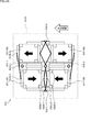
- the single IMU1 has, for example, an acceleration sensor that detects acceleration that is translational motion in each of the three axial directions consisting of XYZ axes, and a gyro sensor that detects angular velocity that is rotational motion. It is configured to be equipped with, and detects acceleration and angular velocity in each of the three axial directions.
- IMU1s Although there are high-precision IMU1s as a single unit, the higher the precision, the larger and more expensive it is. If you try to make it more accurate, the size will increase and the cost will increase.
- low-precision but inexpensive IMU1s are provided, for example, in a plurality (for example, n), such as IMU1-1 to 1-n.
- the synthesizer 2 synthesizes the acceleration and angular velocity, which are the detection results of IMU1-1 to 1-n, to reduce the noise density and bias fluctuation to 1 / ⁇ n, and improve the detection accuracy.
- the multi-IMU10 is designed to be highly accurate.
- the device size and device cost related to the individual low-precision and inexpensive IMUs 1-1 to 1-n constituting the multi-IMU10 shown in the right part of FIG. 1 are the high-precision IMU1 as shown in the left part of FIG. It is possible to sufficiently reduce the size and cost of the device when the device is prepared as a single unit, and it is possible to reduce the cost.
- IMU1 when it is not necessary to distinguish between IMU1-1 to 1-n, they are simply referred to as IMU1 and other configurations are also referred to in the same manner. Further, in the present specification, the IMU1 is a small, inexpensive IMU having a relatively low accuracy, but is a large, expensive, and highly accurate IMU. You may.
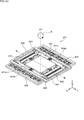
- each IMU 1 constituting the multi-IMU 10 reads the vibration of the oscillator 11 made of silicon, the base 12 for fixing the oscillator 11, and the oscillator 11 from the upper part of the figure. , Composed of a readout circuit 13 that outputs the angular velocity, which are bonded (bonded) in the order shown in the right part of FIG. 2 and integrated by a resin mold as shown in the left part of FIG. It is a thing.
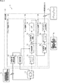
- FIG. 3 describes the configuration for detecting the angular velocity among the read circuits constituting the IMU1. Since the configuration for detecting the acceleration in the IMU1 is a configuration in which the detection circuit is excluded from the configuration for detecting the angular velocity, a configuration for detecting a more complicated angular velocity will be specifically described.
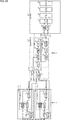
- the read circuit 13 is composed of a drive circuit block 31, a sense circuit block 32, and a digital output circuit block 33.
- the drive circuit block 31 supplies an oscillation signal having a predetermined drive frequency to the oscillator 11 composed of MEMS (Micro Electro Mechanical Systems) and the sense circuit block 32, and vibrates the oscillator 11 based on the oscillation signal. Let me. It will be.
- MEMS Micro Electro Mechanical Systems
- the sense circuit block 32 detects the vibration generated in response to the Coriolis force acting on the vibrator 11 that vibrates based on the oscillation signal as an analog signal, and outputs the vibration to the digital output circuit block 33.
- the digital output circuit block 33 converts the vibration generated in response to the Coriolis force acting on the vibrator 11 supplied from the sense circuit block 32 from an analog signal to a digital signal, and outputs the vibration as an angular velocity.
- the drive circuit block 31 includes an oscillation circuit 51 and an automatic gain adjustment circuit 52.
- the oscillation circuit 51 is composed of RC, generates an oscillation signal using the vibration supplied from the oscillator 11 as a reference signal, and outputs the oscillation signal to the automatic gain adjustment circuit 52 and the phase shift circuit 72 of the sense circuit block 32.
- the automatic gain adjustment circuit 52 adjusts the gain of the oscillation signal consisting of the drive frequency supplied from the oscillation circuit 51, supplies the gain to the oscillator 11, and vibrates the oscillator 11.
- the sense circuit block 32 includes a charge amplifier circuit 71, a phase shift circuit 72, a synchronous detection circuit 73, and an LPF 74.
- the charge amplifier circuit 71 detects the vibration of the vibrator 11 as a vibration signal, amplifies it, and supplies it to the phase shift circuit 72.
- the phase shift circuit 72 adjusts the phase of the vibration signal of the vibrator 11 detected by the charge amplifier circuit 71 based on the oscillation signal supplied from the oscillation circuit 51, and outputs the phase to the synchronous detection circuit 73.
- the synchronous detection circuit 73 detects a waveform indicating the Coriolis force acting on the oscillator 11 expressed by the envelope from the vibration signal of the oscillator 11 whose phase is adjusted, and outputs the waveform to the LPF 74.
- the LPF 74 smoothes the waveform indicating the Coriolis force acting on the vibrator 11 and outputs it to the digital output circuit block 33 as information on the angular velocity composed of an analog signal.
- the digital output circuit block 33 includes an AD conversion circuit 91, a decimation filter 92, and a digital output circuit 93.
- the AD conversion circuit 91 converts the information of the angular velocity consisting of the Coriolis force acting on the vibrator 11 consisting of an analog signal into a digital signal and outputs it to the decimation filter 92.
- the decimation filter 92 averages the information of the angular velocity composed of the digital signal and outputs it to the digital output circuit 93.
- the digital output circuit 93 outputs digitized and averaged angular velocity information as a digital signal.
- the oscillator 11 is oscillated by the oscillation circuit 51 and vibrates based on a reference signal consisting of an oscillation signal having a drive frequency fb whose gain is adjusted by the automatic gain adjustment circuit 52. ..
- the amplitude modulation by the colliori force is applied, so that, for example, the waveform output from the charge amplifier circuit 71 is shown by the waveform fbc with respect to the drive frequency fb.
- the amplitude is modulated according to the collior force.
- the synchronous detection circuit 73 detects the amplitude modulation by the Coriolis force from the envelope of the waveform fbc as the Coriolis force, that is, the waveform of the analog signal indicating the angular velocity, and outputs it to the LPF74.
- the waveform of the analog signal extracted as the collior force in this way is converted into a digital signal by the digital output circuit block 33 and output as a digitized angular velocity value.
- n pieces of the above-mentioned IMU1 are collected and accumulated, and the angular velocities detected by each of IMU1-1 to 1-n are synthesized by the synthesizer 2. Output with high accuracy.
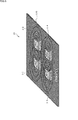
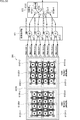
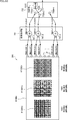
- the multi-IMU 10 has a configuration as shown in FIG. 6, for example.
- IMU 1-1 to IMU 1-4 are provided on the printed circuit board 110.
- the angular velocities detected by each of IMU1-1 to IMU1-4 are combined, and the detection accuracy is improved and output.
- the IMU1 is manufactured with a variation in the drive frequency of, for example, about 3% due to individual differences in manufacturing.
- the drive frequency of the IMU1-1 is 20.000 kHz as shown by IMU1-1 to IMU1-4 in FIG. It may be configured so that the drive frequency of IMU1-2 is driven at 20.010 kHz, the drive frequency of IMU1-3 is driven at 19.900 kHz, and the drive frequency of IMU1-1 is driven at 20.020 kHz.
- the reference signal consisting of the oscillation signal of the drive frequency fb output via the automatic gain adjustment circuit 52 in the predetermined IMU1 is the reference signal of another IMU1 existing in the vicinity.
- the reference signal consisting of the drive frequency fb'( ⁇ fb) becomes disturbance (acoustic vibration), causing interference, and the reference signal actually supplied to the vibrator 11 undergoes amplitude modulation according to the frequency difference. It will be supplied to the oscillator 11 as an amplitude-modulated signal fe including a growl.
- the reference signal consisting of the drive frequency fb is supplied to the vibrator 11
- the reference signal supplied to the vibrator 11 due to the disturbance is an amplitude modulation signal.
- the angular velocity is detected as an amplitude-modulated signal, which is shown by a thick line in the figure, with respect to the waveform fc originally detected as the angular velocity, so that an error occurs in the angular velocity.
- the beat occurs as vibration of the frequency corresponding to the mutual frequency difference between IMU1-1 to IMU1-4.
- the beat frequency between IMU1-1 and IMU1-2 is 10 Hz, which is the drive frequency difference between the two
- the beat frequency between IMU1-1 and IMU1-3 is both.
- the drive frequency difference is 100 Hz
- the beat frequency between IMU1-1 and IMU1-3 is 20 Hz, which is the drive frequency difference between the two.
- the beat frequency between IMU1-2 and IMU1-3 is 110 Hz, which is the difference between the drive frequencies of both, and the beat frequency between IMU1-2 and IMU1-4 is 10 Hz, which is the difference between the drive frequencies of both, and IMU1-3.
- the beat frequency with IMU1-4 is 120Hz, which is the difference between the drive frequencies of both.
- IMU1-1 to IMU1-4 detect the angular velocity including the error in IMU1-1 to IMU1-4 because the error vibration of the swell frequency is superimposed due to the interference generated by the mutual reference signal. Therefore, even if these are combined, there is a risk that an appropriate angular velocity cannot be obtained.
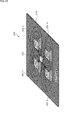
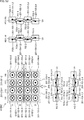
- the IMUs 201-1 to 201-4 are arranged on the printed circuit board 210.
- the printed circuit boards 210 and IMU201-1 to 201-4 in the multi-IMU200 of FIG. 9 have configurations corresponding to the printed circuit boards 110 and IMU1-1 to 1-4 in the IMU10 of FIG. 6, respectively.
- the number of IMU 201s arranged on the printed circuit board 210 is not limited to four IMU201-1 to 201-4 as shown in FIG. 9, and may be any other number.
- the IMU201-1 supplies the oscillation signal for driving itself as a reference signal fm to the remaining IMU201-2 to 201-4, and then supplies the IMU201-. 2 to 201-4 are driven based on the reference signal fm supplied from IMU2011-1.
- the IMU201 supplied to the remaining IMU201 with its own oscillation signal as the reference signal fm is also referred to as a synchronous master device, and is supplied from the IMU201 set in the synchronous master device.
- the IMU 201 driven by the reference signal fm is also referred to as a synchronous slave device.
- IMU201-1 is a synchronization master device, and the other IMU201-2 to 201-4 are synchronization slave devices.
- the drive frequency of the oscillation signal supplied from the synchronous master device IMU2011-1 becomes the reference drive frequency
- the reference signal fm composed of the oscillation signal of the reference operating frequency becomes the reference drive frequency from the synchronous master device IMU2011-1. It is supplied to IMU201-2 to 2014-4 which are synchronous slave devices. Then, the IMUs 201-2 to 201-4 that function as the synchronous slave device are driven by the oscillation signal of the reference drive frequency, which is the reference signal fm.
- IMU201-2 to 201-4 which are synchronous slave devices, are supplied, and all of IMU201-1 to 201-4 are driven by the same reference signal fm.
- the reference signal fm output from IMU201-1 is supplied to IMU201-2 and IMU201-3, and further, from IMU201-1 via IMU201-2 and IMU201-3.
- the supplied reference signal fm is supplied to IMU201-4.
- the IMU201 serving as the synchronization master device may be any of IMU201-1 to 201-4.
- the reference signal fm may be directly supplied from the IMU 201 which is the synchronization master device to the IMU 201 which is the synchronization slave device, or may be supplied via the IMU 201 which is another synchronization slave device.
- the IMUs 201-1 to 201-4 can be driven synchronously at the same drive frequency to suppress the generation of swells due to mutual interference. Therefore, the IMUs 201-1 to 201- It is possible to suppress the occurrence of an error in the angular velocity detected in each of the above, and it is possible for each of them to detect the angular velocity with high accuracy.
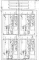
- the IMU201-1 functioning as a synchronization master device and the IMU201-2 functioning as a synchronization slave device are shown.
- the appearance configuration and the circuit configuration of the read circuit are shown.
- IMU201-3 and 201-4 which are other IMU201s that function as synchronous slave devices, are the same as those of IMU201-2 that functions as synchronous slave devices, so the description thereof will be omitted as appropriate. do.
- Both IMU201-1 and 201-2 are provided on the same printed circuit board 210, detect angular velocities, and output to the synthesis unit 202.
- the synthesizing unit 202 synthesizes the angular velocities detected by each of IMU201-1 to 2014-4, and outputs the information of the synthesized angular velocities as the detection result.
- the IMU201-1 is a reading circuit that reads the vibration of the oscillator 211-1 made of MEMS, the base 212-1 fixing the oscillator 211-1, and the oscillator 211-1 from the top of the figure, and outputs the angular velocity. It is composed of 213-1.
- the oscillator 211-1 has the same basic functions as the oscillator 11 in FIG. 3, the description thereof will be omitted.
- the IMU201-2 reads the vibrations of the oscillator 211-2 made of MEMS, the base 212-2 for fixing the oscillator 211-2, and the oscillator 211-2 from the top of the figure, and outputs the angular velocity. It is composed of a read circuit 213-2.
- the read circuit 213-1 is composed of a drive circuit block 231-1, a sense circuit block 232-1, and a digital output circuit block 233-1.
- the drive circuit block 231-1, the sense circuit block 232-1, and the digital output circuit block 233-1 correspond to the drive circuit block 31, the sense circuit block 32, and the digital output circuit block 33 in FIG. 3, respectively. Is.
- the drive circuit block 231-1 includes an oscillation circuit 251-1 and an automatic gain adjustment circuit 252-1.
- the oscillation circuit 251-1 and the automatic gain adjustment circuit 252-1 have the same basic functions as the oscillation circuit 51 and the automatic gain adjustment circuit 52 in FIG. 3, the description thereof will be omitted.
- the IMU201-1 functions as a synchronization master device
- the IMU201 functions as a synchronization slave device using the oscillation signal output from the oscillation circuit 251-1 as the reference signal fm via the automatic gain adjustment circuit 252-1. It is output to the oscillation circuits 251-2 to 251-4 of -2 to 201-4.
- the sense circuit block 232-1 includes a charge amplifier circuit 271-1, a phase shift circuit 272-1, a synchronous detection circuit 273-1 and an LPF274-1.
- the charge amplifier circuit 271-1, the phase shift circuit 272-1, the synchronous detection circuit 273-1, and the LPF274-1 are the charge amplifier circuit 71, the phase shift circuit 72, the synchronous detection circuit 73, and the LPF74 in FIG. 3, respectively. Since the basic functions are the same as those of the above, the description thereof will be omitted.
- the digital output circuit block 233-1 includes an AD conversion circuit 291-1, a decimation filter 292-1, and a digital output circuit 293-1.
- the AD conversion circuit 291-1, the decimation filter 292-1, and the digital output circuit 293-1 have basically the same functions as the AD conversion circuit 91, the decimation filter 92, and the digital output circuit 93 in FIG. 3, respectively. Therefore, the description thereof will be omitted as appropriate.
- the read circuit 213-2 is composed of a drive circuit block 231-2, a sense circuit block 232-2, and a digital output circuit block 233-2.
- the drive circuit block 231-2, the sense circuit block 232-2, and the digital output circuit block 233-2 have configurations corresponding to the drive circuit block 31, the sense circuit block 32, and the digital output circuit block 33 of FIG. 3, respectively. Is.
- the drive circuit block 231-2 includes an oscillation circuit 251-2 and an automatic gain adjustment circuit 252-2.
- the oscillation circuit 251-2 and the automatic gain adjustment circuit 252-2 have the same basic functions as the oscillation circuit 51 and the automatic gain adjustment circuit 52 in FIG. 3, their description will be omitted.
- the oscillation circuit 251-2 receives the input of the reference signal fm supplied from the IMU201-1 which is the synchronous master device, and performs a pull-in operation. It is driven in synchronization with the reference drive frequency (PLL (Phase Locked Loop) locked), which is the drive frequency of the reference signal fm.
- PLL Phase Locked Loop
- the sense circuit block 232-2 includes a charge amplifier circuit 271-2, a phase shift circuit 272-2, a synchronous detection circuit 273-2, and an LPF274-2.
- the charge amplifier circuit 271-2, the phase shift circuit 272-2, the synchronous detection circuit 273-2, and the LPF274-2 are the charge amplifier circuit 71, the phase shift circuit 72, the synchronous detection circuit 73, and the LPF74 in FIG. 3, respectively. Since the basic functions are the same as those of the above, the description thereof will be omitted.
- the digital output circuit block 233-2 includes an AD conversion circuit 291-2, a decimation filter 292-2, and a digital output circuit 293-2.
- the AD conversion circuit 291-2, the decimation filter 292-2, and the digital output circuit 293-2 have basically the same functions as the AD conversion circuit 91, the decimation filter 92, and the digital output circuit 93 in FIG. 3, respectively. Therefore, the description thereof will be omitted as appropriate.
- the oscillation circuit 251-1 of the IMU2011 which is the synchronization master device supplies the reference signal fm composed of the oscillation signal of the reference drive frequency to the IMUs 201-2 to 2012-4 which are the synchronization slave devices. do.
- the oscillation circuits 251-2 to 251-4 of the IMUs 201-2 to 201-4 which are synchronous slave devices, have a multi-IMU200 in which the drive frequency is PLL-locked by the reference signal fm composed of the oscillation signal of the reference drive frequency. It is possible to synchronize all the IMUs 201-1 to 201-4 constituting the above and drive them with an oscillation signal having the same drive frequency. As a result, it is possible to suppress the occurrence of beats caused by different drive frequencies of the plurality of IMU 201s and detect the angular velocity with high accuracy.
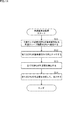
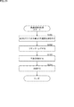
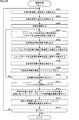
- step S11 the oscillation circuit 251-1 of the IMU2011 which is the synchronization master device refers to the oscillation signal whose own drive frequency is the reference drive frequency with respect to the synchronization slave devices IMU201-2 to 201-4. It is transmitted as a signal fm.
- step S12 the oscillation circuits 251-2 to 251-4 of all the IMUs 201-2 to 201-4 are PLL-locked to the oscillation signal of the drive frequency of the oscillation circuit 251-1 based on the reference signal fm.
- IMU2011-1 to 201-4 can measure the angular velocity with high accuracy.
- step S13 all IMUs 201-1 to 201-4 detect the angular velocity and output it to the synthesis unit 202.
- step S14 the synthesis unit 202 synthesizes the angular velocities supplied from each of IMU201-1 to 201-4, and outputs the angular velocity as the synthesis result as the detection result by the multi-IMU200.
- all the IMUs 201-1 to 201-4 constituting the multi-IMU200 can be driven synchronously based on the reference signal fm composed of the oscillation signals having the same drive frequency. It is possible to suppress the occurrence of errors due to it, and it is possible to detect the angular velocity with high accuracy.
- any one of the plurality of IMUs 201-1 to 201-4 constituting the multi-IMU200 is set in the synchronous master device, the other IMU201 is set in the synchronous slave device, and the drive frequency of the synchronous master device is set.
- the reference drive frequency By setting the reference drive frequency and supplying the reference signal fm consisting of the oscillation signal of the reference drive frequency from the IMU201 which is the synchronization master device, all the IMUs 201-1 to 201-4 are driven at the same drive frequency.
- An example of suppressing the occurrence of an error and enabling the detection of the angular velocity with high accuracy has been described.
- the reference drive frequency is significantly different from the drive frequency of the synchronous slave device, the frequency cannot be drawn in the oscillation circuit 251 and the PLL lock. May not be applied.
- the IMU 201 which is the synchronous slave device cannot draw in the drive frequency of the reference signal fm and the PLL lock cannot be applied, the IMU 201 which is the synchronous slave device has the drive frequency of the IMU 201 which is the synchronous master device. Cannot operate in sync with.
- the drive frequencies of a plurality of IMUs 201-1 to 201-4 constituting the multi-IMU200 are measured, the IMU201 having a drive frequency close to the median is set in the synchronous master device, and the other IMU201s are set in the synchronous slave device. Therefore, the accuracy of drawing into the reference drive frequency, which is the drive frequency of the reference signal fm, may be improved.
- the drive frequencies of a plurality of IMUs 201-1 to 201-4 constituting the IMU200 are measured, the IMU201 having a drive frequency close to the median is set in the synchronous master device, and the other IMU201s are set in the synchronous slave device.
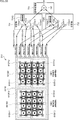
- An example of the configuration of the multi-IMU200 is shown.
- the configuration different from that of the multi-IMU200 of FIG. 9 is that a switching circuit 301 is newly provided.
- the switching circuit 301 detects the drive frequency of each of the oscillation circuits 251-1 to 251-4 of the IMUs 211-1 to 201-4 constituting the multi-IMU200 of FIG. 12, and detects the median value.
- the IMU201 of the drive frequency to be used is set in the synchronization master device, and the other IMU201s are set in the synchronization slave device.
- the switching circuit 301 is set in the synchronous slave device by using the oscillation signal of the drive frequency supplied from the oscillation circuit 251 of the IMU 201 set in the synchronous master device as the reference signal fm which is the oscillation signal of the reference drive frequency. It is supplied to the oscillation circuit 251 of the IMU 201.
- the IMU201 set in the synchronous slave device is PLL-locked based on the reference signal fm composed of the oscillation signal having the same drive frequency as the IMU201 set in the synchronous master device, and all the IMU201s constituting the multi-IMU200 are configured.
- -1 to 201-4 can detect the angular velocity in synchronization with the oscillation signals of the same drive frequency.
- the drive frequency of the IMU201-1 is close to the median of the drive frequencies of the IMU201-1 to 201-4.
- An example is shown in which the frequency is set to the synchronization master device and the IMUs 201-2 to 201-4 are set to the synchronization slave device. Therefore, in FIG. 12, the switching circuit 301 acquires the oscillation signal of the IMU201-1 which is the synchronization master device as the reference signal fm, and supplies the IMUs 201-2 to 201-4 set in the synchronization slave device. This is schematically represented by an arrow.
- FIG. 13 shows a circuit configuration composed of the read circuits 213-1 to 213-4 of the IMUs 211-1 to 201-4 constituting the multi-IMU200 of FIG. 12 and the switching circuit 301, respectively. There is.
- each configuration of IMU201-1 to 201-4 in FIG. 13 is basically the same as the configuration in FIG. 10, and IMU201-1 to 201-4 are identified by the reference numerals of "-" and the like.
- the switching circuit 301 is connected to the outputs of the oscillation circuits 251-1 to 251-4 and the input of the reference signal to each of them.
- the switching circuit 301 monitors the oscillation signals output from each of the oscillation circuits 251-1 to 251-4 to obtain the drive frequency, and sets the IMU 201 equipped with the oscillation circuit 251 as the median value in the synchronization master device. , Other IMU201 is set as a synchronous slave device.
- the switching circuit 301 supplies the oscillation signal output from the oscillation circuit 251 of the IMU 201 set in the synchronization master device as the reference signal fm to the IMU 201 set in the synchronization slave device.
- the oscillation circuit 251 of the IMU 201 set in the synchronous slave device is driven at the same drive frequency as the oscillation circuit 251 of the IMU 201 set in the synchronous master device by PLL-locking to the drive frequency of the supplied reference signal fm. ..
- the IMU set in the synchronization master device and the IMU 201 set in the synchronization slave device are driven at the same drive frequency.
- step S31 the switching circuit 301 drives all the oscillation circuits 251-1 to 251-4 of IMU201-1 to 201-4 to detect the drive frequency of the oscillation signal.
- step S32 the switching circuit 301 identifies the IMU201 that is close to the median among the drive frequencies of the oscillation signals of all the oscillation circuits 251-1 to 251-4 of the detected IMU201-1 to 201-4.
- step S33 the switching circuit 301 sets the IMU201 close to the median as the synchronization master device, and sets the other IMU201s as the synchronization slave device.
- step S34 the switching circuit 301 switches the connection, extracts the oscillation signal of the oscillation circuit 251 of the IMU 201 set in the synchronization master device as the reference signal fm, and connects to the oscillation circuit 251 of the IMU 201 set in the synchronization slave device. Supply.
- step S35 the oscillation circuits 251-1 to 251-4 of all the IMUs 201-1 to 2014-4 are the oscillation signals of the drive frequency of the oscillation circuit 251 of the IMU201 which is the synchronization master device based on the reference signal fm. PLL lock to.
- step S36 all IMUs 201-1 to 201-4 detect the angular velocity and output it to the synthesis unit 202.
- step S37 the synthesis unit 202 synthesizes the angular velocities supplied from each of IMU201-1 to 201-4, and outputs the angular velocity as the synthesis result as the detection result by the multi-IMU200.
- all the IMUs 201-1 to 201-4 constituting the multi-IMU200 can be driven synchronously based on the reference signal fm composed of the oscillation signals having the same drive frequency. It is possible to suppress the occurrence of errors due to it, and it is possible to detect the angular velocity with high accuracy.
- the drive frequency of the IMU201 set in the synchronous master device is set to the median value of all the IMU201s, it is the same as the drive frequency of the reference signal fm supplied to the IMU201 set in the synchronous slave device. Since the difference is minimized, it is easy to pull in to the reference drive frequency, the PLL lock is not applied, and it is possible to suppress the state in which synchronization cannot be performed.
- Second variant of the first embodiment >>
- the drive frequencies of a plurality of IMUs 201-1 to 201-4 constituting the multi-IMU200 are measured, the IMU201 having a drive frequency close to the median is set as the synchronous master device, and the other IMU201s are set as the synchronous slave device.
- the reference signal fm is generated separately from the IMUs 201-1 to 201-4 to generate the IMU2011-1 to A configuration for supplying to 201-4 may be provided.
- FIG. 15 shows a configuration example of a multi-IMU 200 in which a reference generating unit for generating a reference signal fm is provided in the IMU 200 so that the reference signal fm is supplied to the IMUs 201-1 to 201-4.
- the configuration different from that of the multi-IMU200 of FIG. 9 is that a reference generation unit 321 is newly provided.
- the reference generation unit 321 In manufacturing the IMU201, the reference generation unit 321 generates an oscillation signal having a drive frequency as a design value as a reference drive frequency as a reference signal fm, and supplies the oscillation signals to the IMUs 201-1 to 201-4.
- the reference generator 321 is connected to the oscillation circuits 251-1 to 251-4 of the IMUs 201-1 to 201-4 constituting the multi-IMU200 of FIG.
- the generated reference signal fm is supplied to the oscillation circuits 251-1 to 251-4 of the respective IMUs 201-1 to 201-4.
- the IMUs 201-1 to 201-4 are PLL-locked based on the reference signal fm supplied from the reference generator 321 and all the IMUs 201-1 to 201-4 constituting the multi-IMU200 are set to the reference signal fm. It is possible to detect the angular velocity in synchronization with.
- the reference generation unit 321 substantially functions as a synchronization master device, the IMU2011-1 to 201-4 function as a synchronization slave device, and the reference generation unit 321 sets the reference signal fm to the IMU201.
- Supplying to all of -1 to 201-4 is schematically represented by an arrow.
- FIG. 16 shows a circuit configuration composed of the read circuits 213-1 to 213-4 of the IMUs 211-1 to 201-4 constituting the multi-IMU200 of FIG. 15 and the reference generator 321. ing.
- IMU201-1 to 201-4 is basically the same as the configuration in FIG. 10, and IMU201-1 to 201-4 are identified by the reference numerals of "-" and below.
- step S51 the reference generation unit 321 sets itself as a synchronization master device, and sets all IMUs 201-1 to 201-4 as synchronization slave devices.
- step S52 the reference generation unit 321 supplies the reference signal fm to each of the oscillation circuits 251-1 to 251-4 of the IMUs 201-1 to 201-4 set in the synchronous slave device.
- step S53 the oscillation circuits 251-1 to 251-4 of all the IMUs 201-1 to 201-4 set the drive frequency of the oscillation circuits 251-1 to 251-4 based on the reference signal fm. PLL lock to the drive frequency of the reference signal fm.
- step S54 all IMUs 201-1 to 201-4 detect the angular velocity and output it to the synthesis unit 202.
- step S55 the synthesis unit 202 synthesizes the angular velocities supplied from each of IMU201-1 to 201-4, and outputs the angular velocity as the synthesis result as the detection result by the multi-IMU200.
- all the IMUs 201-1 to 201-4 constituting the multi-IMU200 can be driven synchronously based on the reference signal fm composed of the oscillation signals having the same drive frequency. It is possible to suppress the occurrence of errors due to it, and it is possible to detect the angular velocity with high accuracy.
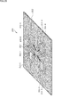
- the oscillators 211-1 to 211-4 of the IMUs 211-1 to 201-4 are formed on a base 212 made of common silicon, the IMU201-1 is set in the synchronous master device, and the IMUs 201-2 to 21-4 are set.
- An example is shown in which 201-4 is set as a synchronous slave device.
- the oscillation signal of the drive frequency generated from the oscillation circuit 251-1 of the IMU2011 set as the synchronization master device as shown in FIG. 19 is set as the reference signal fm as the synchronization slave device. It is supplied to the oscillation circuit 251-2 of the IMU201-2.
- the oscillation circuit 251-2 of the IMU201-2 set as the synchronization slave device is drawn into the drive frequency of the reference signal fm, so that the oscillation circuit 251-1 of the IMU201-1 set as the synchronization master device It is driven in synchronization with the drive frequency.
- the synchronous master device By supplying the reference signal fm to the IMU 201-3, 201-4 set as the synchronous slave device, the synchronous master device also for the oscillation circuits 251-3 and 251-4 of the IMU 201-3, 201-4. It is driven in synchronization with the drive frequency of the oscillation circuit 251-1 of the IMU2011 set as.
- the oscillators 211-1 to 211-4 of IMU2011-1 to 201-4 are formed on the base 212 made of common silicon, one of them is set in the synchronous master device, and the others are set. Although the multi-IMU 200 set in the synchronous slave device has been described, the switching circuit 301 described above may be further provided on the base.
- the switching circuit 301 is provided on the printed circuit board 210 on which the IMUs 201-1 to 201-4 are formed has been described, but the switching circuit having the same function is provided. May be formed on the base 212 on which the oscillators 211-1 to 211-4 are formed.
- FIG. 20 is a configuration example of the multi-IMU 200 in which the switching circuit 301', which has the same function as the switching circuit 301, is formed on the base 212 on which the vibrators 211-1 to 211-4 are formed. ..
- the oscillators 211-1 to 211-4 of the IMUs 211-1 to 201-4 are formed on the base 212 made of common silicon, and the switching circuit 301'is further provided on the base 212. I have explained an example of making it.
- a reference generator having the same function as the reference generator 321 may be formed instead of the switching circuit 301.
- FIG. 20 An example in which the switching circuit 301'is provided on the printed circuit board 210 on which the IMUs 201-1 to 201-4 are formed has been described, but instead of the switching circuit 301', FIG. A reference generation unit having the same function as the reference generation unit 321 of the above may be formed on the base 212 on which the oscillators 211-1 to 211-4 are formed.
- FIG. 21 shows a configuration example of the multi-IMU 200 in which the reference generator 321', which has the same function as the reference generator 321, is formed on the base 212 on which the oscillators 211-1 to 211-4 are formed. Is shown.
- a sixth modification of the first embodiment >>
- the occurrence of beats is suppressed and the accuracy of the detected angular velocity is improved.
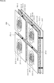
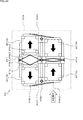
- the oscillators 211-1 of IMU201-1 to 2014-4 To 211-4 are formed on physically independent bases, and noise is removed by sandwiching an acoustic insulator with respect to a common contact portion where each is arranged. good.
- the vibrators 211-1 to 211-4 of the IMUs 211-1 to 201-4 are formed on independent bases, and further, acoustically at a contact position with a common portion where the respective bases are arranged.
- An example of the configuration of the multi-IMU 200 that mechanically reduces the acoustic interference level by sandwiching the insulator is shown.
- the same reference numerals are given to the configurations having the same functions as the multi-IMU200 of FIG. 18, and the description thereof will be omitted as appropriate.
- the difference from the multi-IMU200 of FIG. 18 is that the vibrators 211-1 to 211-4 replace the base 212 with the base 212'-1 and the base 212'-2-1 to. 212'-2-4 and acoustic insulators 351-1 to 351-4 are provided.
- the vibrators 211-1 to 211-4 are formed on the bases 212'-2-1 to 212'-2-4 each made of physically independent silicon.
- the bases 212'-2-1 to 212'-2-4 which are physically independent of each other, are formed on a common base 212-1 with the acoustic insulators 351-1 to 351-1 in between, respectively. ..
- the acoustic insulators 351-1 to 351-4 are configured to absorb vibrations, are formed on a base 212-2 common to the vibrators 211-1 to 211-4, and are formed on the base 212'-2-1, respectively. ⁇ 212'-2-4 is supported.
- the acoustic insulators 351-1 to 351-4 absorb the vibrations generated in the vibrators 211-1 to 211-4 and the base 212, respectively, so that the vibrators 211-1 to 211-4 are used. Since each vibration of the above is isolated, the transmission of mutual vibration is suppressed.
- the vibrators 211-1 to 211-4 of IMU201-1 to 201-4 are formed on independent bases, and further, acoustically at a contact position with a common part where each base is arranged. An example of removing noise that cannot be removed even if the drive frequencies of the IMUs 201-1 to 201-4 are synchronized by sandwiching the insulator has been described.
- noise that cannot be removed even if the drive frequencies of IMU201-1 to 201-4 are synchronized may be removed by directly detecting the beat and generating a reverse phase signal of the detected beat.
- FIG. 23 is a configuration example of the IMU 201 in which a beat is detected from an oscillation signal output from the oscillation circuit 251 and a reverse phase signal of the detected beat is generated to eliminate the beat.
- the beat detection circuit 371 detects the beat signal fg from the oscillation signal output by the oscillation circuit 251 and generates the reverse phase signal fg-1 of the beat signal and supplies it to the synthesizer 372.
- the synthesizing unit 372 synthesizes the reverse phase signal fg-1 of the beat signal with the signal output from the phase shift circuit 272 to remove the beat component from the signal output from the phase shift circuit 272, and synchronizes detection. Output to circuit 273.
- Second embodiment >> In the above, an example has been described in which the IMUs 201-1 to 201-4 synchronize the drive frequencies to suppress the occurrence of beats and enable the detection of the angular velocity with high accuracy.
- the drive frequency of the IMU 201 is significantly different from the drive frequency of the synchronous slave device, it may not be retracted in the oscillation circuit 251 and the PLL lock may not be applied.
- the drive frequencies of a plurality of IMU201s are measured, a cluster of IMU201s capable of synchronizing the drive frequencies as described above is formed, the drive frequencies are synchronized in the cluster unit, the angular velocity is detected, and the angular velocity is detected in the cluster unit. It is also possible to improve the detection accuracy of the angular velocity by acquiring the obtained angular velocity in time division and synthesizing it.
- the drive frequency of the oscillation signal for driving IMU2011, 201-3 is 20.000 kHz
- the drive frequency of the oscillation signal for driving IMU201-2, 2010-4 is 20.100.
- the drive frequencies of the IMUs 201-1 and 201-3 are the same as each other based on the drive frequencies of the oscillation signals that drive each of the IMUs 201-1 to 201-4, and are therefore shown in FIG. 24.
- the clusters are formed as clusters 411-1, and further, since the drive frequencies of IMU201-2 and 201-4 are the same as each other, they are clustered so as to be formed as another cluster 411-2.
- the drive frequency of the IMU 201 is synchronized in the cluster unit by setting the synchronization master device and the synchronization slave device in each cluster 411-1, 411-2. In order to detect the angular velocity.
- the angular velocity detected in the cluster unit is acquired in time division and synthesized, so that the angular velocity can be detected with higher accuracy.
- Clustering of a plurality of IMU201s provided in the multi-IMU200 is performed as a part of the manufacturing process of the multi-IMU200.
- clustering is performed by the clustering measuring device 451 and the connection portion 452 in FIG. 25.
- the clustering measuring device 451 is used in the manufacturing process of the multi-IMU200, and has a configuration separate from the multi-IMU200.
- the clustering measuring device 451 measures the drive frequency output from each oscillation circuit 251 of the plurality of IMU 201s provided in the multi-IMU 200, and the measured drive frequencies are similar and can be driven by the same drive frequency. Is made into the same cluster, and information indicating which cluster each IMU 201 belongs to is output to the connection unit 452.
- the clustering measurement device 451 includes a reference frequency generation unit 461, a frequency measurement unit 462, and a clustering calculation unit 463.
- the reference frequency generation unit 461 generates a reference frequency and outputs it to the frequency measurement unit 462 when measuring the drive frequencies of a plurality of IMU201s.
- the frequency measurement unit 462 measures the drive frequency of the oscillation signal output from the oscillation circuit 251 of each IMU201 based on the reference frequency supplied from the reference frequency generation unit 461 (monitors the oscillation monitor output), and performs clustering calculation. Output to unit 463.
- the clustering calculation unit 463 clusters IMU 201s having similar drive frequencies into the same cluster based on the drive frequency of the oscillation signal output from the oscillation circuit 251 of each IMU 201, and determines which cluster each IMU 201 belongs to.
- the indicated information is output to the connection unit 452.
- the connection unit 452 sets one of the IMU 201s belonging to the same cluster as the synchronization master device based on the information indicating which cluster each IMU 201 supplied from the clustering measuring device 451 belongs to, and sets the other IMU 201s in the synchronization master device.
- a connection is formed so as to connect the output of the automatic gain control circuit 252 of the IMU 201 set in the synchronous slave device and the oscillation master circuit 251 of the IMU 201 set in the synchronous slave device.
- the synthesis of the angular velocities detected for each cluster of the clustered IMU201 is realized by synthesizing the angular velocities detected in time division by the synthesis calculation unit 471 in the cluster unit.
- the synthesis calculation unit 471 is configured separately from the multi-IMU200, but may be integrated with the multi-IMU200.
- the synthesis calculation unit 471 includes a resampler 481, an interference removal unit 482, and a synthesis unit 483.
- the resampler 481 aligns the sampling frequencies of data different for each cluster clustered by the clustering measuring device 451 by using an arbitrary resampling method such as 0th order hold and 1st order interpolation, and outputs the sampling frequency to the interference removing unit 482. ..
- the resampler 481 aligns the sampling frequencies of the angular velocities supplied in each cluster unit.
- the interference removing unit 482 removes the interference component between clusters by, for example, filtering processing, and outputs the interference component to the combining unit 483.
- the processing of the interference removing unit 482 may be omitted because interference does not occur when the drive frequencies of the clusters are separated.
- the synthesis unit 483 synthesizes the angular velocities, which are the detection values detected by each IMU 201, and outputs them as one detection value.
- the synthesizing unit 483 synthesizes one detection value as a simple average value, a weighted average value, or a dynamically weighted average value according to a noise situation of the angular velocity which is the detection value detected by the IMU201.
- a synthesis unit for each cluster may be provided in front of the resampler 481, and the processing of the resampler 481 and the interference removal unit 482 may be performed at an angular velocity set as one detection value for each cluster. ..
- connection unit 452 in cluster units ⁇ Example of wiring>
- IMU2011, 201-3 are set to cluster 411-1 and IMU201-2,201-4 are set to cluster 411-2, as shown in FIG. 24.
- connection unit 452 sets one of the IMU201s in each cluster as the synchronization master device, and sets the other IMU201s as the synchronization slave device.
- the one having the median synchronization frequency may be selected in the cluster.
- IMU201-1 is set as the synchronization master device and IMU201-3 is set as the synchronization slave device.
- connection portion 452 is connected so as to connect the output of the automatic gain adjustment circuit 252-1 of the IMU201-1 and the oscillation circuit 251-3 of the IMU201-3, as shown by the alternate long and short dash line in FIG. do.
- IMU201-2 is set as the synchronization master device and IMU201-4 is set as the synchronization slave device.
- connection portion 452 is connected so as to connect the output of the automatic gain adjustment circuit 252-2 of IMU201-2 and the oscillation circuit 251-4 of IMU201-4, as shown by the alternate long and short dash line in FIG. do.
- FIG. 24 it is clustered into a cluster other than the cluster 411-1 consisting of IMU2011 and 201-3 and the cluster 411-2 consisting of IMU201-2 and 201-4. You may do so.
- it may be clustered into a cluster 411-11 consisting of IMU201-2 and a cluster 411-12 consisting of IMU2011, 201-3, 201-4.
- the IMUs 201-1 to 201-4 are connected by the connection portion 452 as shown in FIG. 27.
- IMU2011-1 is shown by the alternate long and short dash line in FIG. 27.
- the output of the automatic gain adjustment circuit 252-1 and the oscillation circuits 251-3 and 251-4 of IMU201-3 and 201-4 are connected.
- the number of clusters may be two or more. Further, the number of IMU201s to which each cluster belongs may be any number.
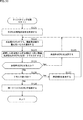
- step S101 the frequency measurement unit 462 measures the drive frequencies of all IMU 201s based on the reference frequency supplied from the reference frequency generation unit 461, and outputs the measurement results to the clustering calculation unit 463.
- step S102 the clustering calculation unit 463 selects the IMU 201 having the lowest drive frequency.
- step S103 the clustering calculation unit 463 sets the IMU within the threshold frequency that is higher by the predetermined width B from the selected drive frequency of the IMU 201 in the same cluster.
- step S104 it is determined whether or not there is an unprocessed unclustered IMU201.
- step S104 If there is an unprocessed unclustered IMU201 in step S104, the process proceeds to step S105.
- step S105 the clustering calculation unit 463 selects an unprocessed IMU 201 having a frequency higher than the threshold frequency, and the process returns to step S102.
- the process of clustering the IMU201s from the lowest drive frequency of the unclustered IMU201s to the threshold frequency higher by the predetermined width B is repeated in the same cluster. That is, IMU201s of drive frequencies within the bandwidth set by the predetermined width B from the lowest drive frequency are clustered in the same class.
- step S105 if it is determined that the unprocessed IMU201 does not exist in step S105, the process proceeds to step S106.
- step S106 the clustering calculation unit 463 outputs information indicating which IMU 201 belongs to which cluster to the connection unit 452.
- the connection unit 452 connects the IMU 201 in cluster units.
- a plurality of IMU201s are clustered based on the drive frequency, and the IMU201s are connected to each cluster.
- the switching circuit 301 of FIG. 12 is used to connect the IMU 201 to each clustered cluster in the same manner as in the connected state.
- the wiring may be switched to.
- step S191 all IMU 201s measure the angular velocity by the oscillation signal of the drive frequency in each cluster and supply it to the synthesis calculation unit 471.
- step S192 the resampler 481 acquires the angular velocity supplied from each IMU 201 in a time-division manner in a cluster unit, aligns the sampling frequencies in the cluster unit, and outputs the angular velocity to the interference removing unit 482.
- step S193 the interference removing unit 482 removes the influence of the interference and outputs the information of the angular velocity supplied from the resampler 481 to the combining unit 483.
- step S194 the synthesis unit 483 synthesizes the information on the angular velocity of each cluster supplied from the interference removal unit 482 and outputs it as one detection value.
- the sampling frequencies of the angular velocities supplied to each cluster consisting of IMU201s whose drive frequencies can be synchronized are aligned, interference is removed, and synthesis is performed. Even when the IMU 201 is used, it is possible to detect the angular velocity with high accuracy.
- the predetermined width B may be increased and the clustering may be redone to cluster the number of clusters up to the specified value N.
- steps S121 to S125 and S128 in the flowchart of FIG. 30 are the same as the processes of steps S101 to S106 of FIG. 28, the description thereof will be omitted.
- the clustering calculation unit 463 determines whether or not the current number of clusters is larger than the specified value N.
- step S126 If the number of clusters is larger than the specified value N in step S126, the process proceeds to step S127.
- step S127 the clustering calculation unit 463 resets the clustering, increases the predetermined width B by a predetermined value, and the process returns to step S122.
- step S127 the processes of steps S122 to S127 are repeated until the number of clusters becomes smaller than the specified value N, and the clustering is repeated again.
- step S127 determines whether the number of clusters is smaller than the specified value N. If it is determined in step S127 that the number of clusters is smaller than the specified value N, the process proceeds to step S128.
- a plurality of IMU201s are clustered into a number of classes smaller than the specified value N based on the drive frequency, and the IMU201s are connected to each cluster.
- Second variant of the second embodiment >> ⁇ Second modification of clustering process>
- the predetermined width B which is the frequency width of each cluster
- the drive frequency is adjusted by trimming the vibrator 211 by laser trimming or the like for the IMU 201 whose measured drive frequency greatly deviates from the design drive frequency. May be good.
- steps S141 to S147 and S150 in the flowchart of FIG. 31 are the same as the processes of steps S101 to S106 of FIG. 28, the description thereof will be omitted.
- step S148 the clustering calculation unit 463 determines whether or not the predetermined width B has been increased and changed.
- step S148 If the predetermined width B is increased and changed in step S148, the process proceeds to step S149.
- step S149 for the IMU 201 whose measured drive frequency deviates more than a predetermined value from the design drive frequency, the vibrator 211 is trimmed by laser trimming or the like so that the drive frequency is appropriate for the design drive frequency. , Processing proceeds to step S150.
- a plurality of IMU201s are clustered into a number of classes smaller than the specified value N based on the drive frequency, the IMU201s are connected for each cluster, and the measured drive frequency is more than predetermined with respect to the design drive frequency.
- the oscillator 211 of the IMU 201 which is greatly deviated from the above, is trimmed so that the drive frequency can be adjusted.
- the clustering of IMU201 may be performed by a clustering method such as the k-means method.
- step S171 the frequency measurement unit 462 measures the drive frequencies of all the IMU 201s based on the reference frequency supplied from the reference frequency generation unit 461, and outputs the measurement results to the clustering calculation unit 463.
- step S172 the clustering calculation unit 463 classifies those having similar drive frequencies into N clusters by the k-means method based on the drive frequencies of all IMU 201s.
- step S173 the clustering calculation unit 463 outputs information indicating which IMU 201 belongs to which cluster to the connection unit 452.
- the connection unit 452 connects the IMU 201 in cluster units.
- a plurality of IMU201s are clustered based on the drive frequency, and the IMU201s are connected to each cluster.
- sense circuit block 232 and the digital output circuit block 233 may be shared by IMU201, which is classified into the same cluster.
- FIG. 33 shows a configuration example of a multi-IMU200 in which the sense circuit block 232 and the digital output circuit block 233 are shared by IMU201s classified into the same cluster.
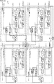
- the multi-IMU200 of FIG. 33 includes IMUs 201'-1 to 201'-4, read circuits 213'-1,213'-2, and a synthesis calculation unit 471'.
- the synthesis calculation unit 471' may be provided outside the multi-IMU200.
- IMU201'-1 and 201'-2 are classified into the first cluster, and IMU201'-3,201'-4 are classified into the second cluster.
- IMU201'-1 is set as the synchronization master device and IMU201'-2 is set as the synchronization slave device. Therefore, the output of the automatic gain adjustment circuit 242-1 of the IMU201'-1 is supplied to the oscillation circuit 251-2 as the reference signal fm via the phase shift circuit 501-2 of the IMU201'-2.
- IMU201'-3 is set as the synchronization master device and IMU201'-4 is set as the synchronization slave device. Therefore, the output of the automatic gain adjustment circuit 242-3 of the IMU201'-3 is supplied to the oscillation circuit 251-4 as the reference signal fm via the phase shift circuit 501-4 of the IMU201'-4.
- IMU201'-1 and 201'-2 share the read circuit 213'-1 in time division
- IMU201'-3,201'-4 divides the read circuit 213'-4 in time division. It is shared by.
- the read circuit 213'-1 reads the angular velocity supplied from the IMU201'-1 at the timing in the first phase, and reads the angular velocity supplied from the IMU201'-2 at the timing in the second phase, and performs a synthesis operation. Supply to unit 471'.
- the read circuit 213'-2 reads the angular velocity supplied from the IMU201'-3 at the timing in the first phase, and reads the angular velocity supplied from the IMU201'-4 at the timing in the second phase, and performs a synthesis operation. Supply to unit 471'.
- the synthesis calculation unit 471' temporarily stores and delays the angular velocities of IMU201'-1 and 201'-3 supplied at the timing of the first phase, and IMU201'-2 supplied at the timing of the second phase. , 201'-4 are acquired together with the angular velocity, first, the angular velocity in the cluster is synthesized, and then the angular velocity for each cluster is resampled, the interference is removed, and the synthesis is performed.
- the IMUs 201'-1 to 201'-4 are provided in the vibrators 211-1 to 211-4 and the read circuit 213, respectively, unlike the configuration of the IMU201 in the multi-IMU200 of FIG. Only the drive circuit blocks 231'-1 to 231'-4 corresponding to the drive circuit block 231 are provided.
- the drive circuit blocks 231'-1 to 231'-4 basically have the same configuration as the drive circuit blocks 231-1 to 231-4, but newly phase shift circuits 501-1 to 501-4. Is equipped with.
- the oscillation circuit 251-1 of the IMU201'-1 adds the oscillation signal to the automatic gain adjustment circuit 252-1 and outputs it as an oscillation monitor output to the terminal 511a-1 of the switch 511-1 in the read circuit 213'-1. do.
- the oscillator 211-1 of the IMU201'-1 outputs the vibration signal as a reference signal to the oscillation circuit 251-1 via the phase shift circuit 501-1, and also outputs the switch 512-1 in the read circuit 213'-1. Output to terminal 512a-1 of.
- the oscillation circuit 251-2 of the IMU201'-2 adds the oscillation signal to the automatic gain adjustment circuit 252-2 and outputs it as an oscillation monitor output to the terminal 511b-1 of the switch 511-1 in the read circuit 213'-1. do.
- the oscillator 211-2 of the IMU201'-2 outputs the vibration signal to the terminal 512b-1 of the switch 512-1 in the read circuit 213'-1.
- the oscillation circuit 251-3 of the IMU201'-3 adds the oscillation signal to the automatic gain adjustment circuit 252-3 and outputs the oscillation signal as an oscillation monitor output to the terminal 511a-2 of the switch 511-2 in the read circuit 213'-2. do.
- the oscillator 211-3 of the IMU201'-3 outputs the vibration signal as a reference signal to the oscillation circuit 251-3 via the phase shift circuit 501-3, and the switch 512-2 in the read circuit 213'-2. Output to terminal 512a-2 of.
- the oscillation circuit 251-4 of the IMU201'-4 adds the oscillation signal to the automatic gain adjustment circuit 252-4 and outputs the oscillation signal as an oscillation monitor output to the terminal 511b-2 of the switch 511-2 in the read circuit 213'-2. do.
- the oscillator 211-4 of the IMU201'-4 outputs the vibration signal to the terminal 512b-2 of the switch 512-2 in the read circuit 213'-2.
- the read circuit 213'-1 has a configuration corresponding to the read circuit 213 in FIG. 10, but only the sense circuit block 232-1 and the digital output circuit block 233-1 excluding the drive circuit block 231 are newly added. Is provided with a switch 511-1.
- the read circuit 213'-2 has a configuration corresponding to the read circuit 213 in FIG. 10, but is limited to the sense circuit block 232-2 and the digital output circuit block 233-2, respectively, excluding the drive circuit block 231.
- a new switch 511-2 is provided.
- the read circuit 213'-1 is shared and used by the IMU201'-1,201'-2 by the time division processing, so that the phase shift circuit 501-1, 501-2 and the switch 511-1 , 512-1 repeats the operation of reading the oscillation signal from IMU201'-1 in the first phase and reading the oscillation signal from IMU201'-2 in the second phase.
- phase shift circuit 501-1, 501-2 outputs the oscillation signal from the IMU201'-1 to the read circuit 213'-1 in the first phase, and the oscillation signal from the IMU201'-2 in the second phase. Is output from the read circuit 213'-1.
- the switch 511-1 is connected to the terminal 511a-1, and the switch 512-1 is connected to the terminal 512a-1.
- the oscillation signal of IMU201'-1 is read out by the read circuit 213'-1 and output to the synthesis calculation unit 471'as an angular velocity composed of a digital signal.
- the switch 511-1 is connected to the terminal 511b-1, and the switch 512-1 is connected to the terminal 512b-1.
- the oscillation signal of IMU201'-2 is read out by the read circuit 213'-1, and is output to the synthesis calculation unit 471'as an angular velocity composed of a digital signal.
- the read circuit 213'-2 is shared by the IMU201'-3,201'-4 by time division processing, the phase shift circuit 501-3, 501-4 and the switch 511-2,512- By the operation of 2, the operation of reading the oscillation signal from IMU201'-3 in the first phase and reading the oscillation signal from IMU201'-4 in the second phase is repeated.
- phase shift circuit 501-3, 501-4 outputs the oscillation signal from the IMU201'-3 to the read circuit 213'-2 in the first phase, and the oscillation signal from the IMU201'-4 in the second phase. Is output from the read circuit 213'-2.
- the switch 511-2 is connected to the terminal 511a-2, and the switch 512-2 is connected to the terminal 512a-2.
- the oscillation signal of IMU201'-3 is read out by the read circuit 213'-2 and output to the synthesis calculation unit 471'as an angular velocity composed of a digital signal.
- the switch 511-2 is connected to the terminal 511b-2, and the switch 512-2 is connected to the terminal 512b-2.
- the oscillation signal of IMU201'-4 is read out by the read circuit 213'-2 and output to the synthesis calculation unit 471'as an angular velocity composed of a digital signal.
- the synthesis calculation unit 471 In addition to the resampler 481 in the synthesis calculation unit 471, the interference elimination unit 482, and the synthesis unit 483, the synthesis calculation unit 471'has a delay adjustment unit 531-1,531-2 and an in-cluster synthesis unit 532-1,5322-. 2 is provided.
- the delay adjusting units 531-1, 531-2 temporarily supply the angular velocities of the second phase. It is stored and delayed, and is output to the in-cluster synthesis unit 532-1,532-2 at the timing when the angular velocity of the second phase is supplied.
- the in-cluster synthesis unit 532-1 synthesizes the angular velocity supplied based on the oscillation signal detected by the IMU201'-1 and 201'-2 constituting the first cluster and outputs it to the resampler 481.
- the in-cluster synthesis unit 532-2 synthesizes the angular velocity supplied based on the oscillation signal detected by the IMU201'-3,201'-4 constituting the second cluster and outputs it to the resampler 481.
- the sense circuit block 232 and the digital output circuit block 233 constituting the read circuit 213' can be shared in cluster units, so that the circuit configuration can be omitted and the cost can be reduced. It becomes possible.
- step S211 the angular velocity by the first phase IMU201'in the same cluster is measured.
- the oscillation signal of the oscillator 211-1 of the IMU201'-1 is supplied to the charge amplifier circuit 271-1.
- the angular velocity detected by IMU201'-1 is measured and output to the synthesis calculation unit 471'.
- step S212 the delay adjusting unit 531 of the synthesis calculation unit 471'temporarily stores the supplied angular velocity of the first phase and delays it until the angular velocity of the second phase is supplied.
- step S213 the angular velocity by the second phase IMU201'in the same cluster is measured.
- the oscillation signal of the oscillator 211-2 of the IMU201'-2 is supplied to the charge amplifier circuit 271-1.
- the angular velocity detected by IMU201'-2 is measured and output to the synthesis calculation unit 471'.
- step S214 the in-cluster synthesis unit 532 acquires the angular velocity of the first layer supplied from the delay adjusting unit 531 and the angular velocity of the second phase, synthesizes the angular velocities in the cluster, and outputs them to the resampler 481. ..
- step S215 the resampler 481 acquires the angular velocity of each cluster, aligns the sampling frequencies of each cluster, and outputs the sampling frequency to the interference removing unit 482.
- step S216 the interference removing unit 482 removes the influence of the interference and outputs the information of the angular velocity supplied from the resampler 481 to the combining unit 483.
- step S217 the synthesis unit 483 synthesizes the information on the angular velocity of each cluster supplied from the interference removal unit 482 and outputs it as one detection value.
- the sampling frequencies of the angular velocities supplied to each cluster consisting of IMU201s whose drive frequencies can be synchronized are aligned, interference is removed, and synthesis is performed. Therefore, a plurality of IMU201s having different drive frequencies are combined. Even when is used, it is possible to detect the angular velocity with high accuracy.
- the read circuit 213' is shared and used for each cluster, by consolidating the read circuits 213'in the device configuration of the multi-IMU200, the device configuration can be miniaturized and the device configuration can be miniaturized. It is possible to reduce the manufacturing cost.
- the angular velocities are measured by synchronizing the drive frequencies of a plurality of IMUs 201, 201'and made the same, or by clustering according to the drive frequencies and synthesizing the angular velocities measured for each cluster, such as beats. An example of removing the noise of the above has been described.
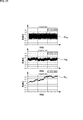
- FIG. 35 shows an example of time-series waveforms of white noise, flicker noise, and random walk noise.
- the waveforms Wwt, Wft, and Wrt show the effects of white noise, flicker noise, and random walk noise on the angular speeds measured in time series, respectively, in order from the top of the figure.
- white noise is constant in the entire frequency band, but flicker noise and random walk noise are both shown to have many low frequency components.
- the vertical axis is intensity
- the horizontal axis is frequency
- the waveform Wwf is a white noise waveform
- the waveform Wff is a flicker noise waveform
- the waveform Wrf is a random walk noise waveform. Is.
- the flicker noise is a rule at the bias stable point, and the flicker noise does not fall below the lower limit of the dispersion even if a noise filter or the like is used. Has been done.
- the Alan variance is shown, the horizontal axis is the width of the time window, and the vertical axis is the variance.
- the waveform Wa is the allan variance of IMU201
- the waveform Wwa is the allan variance of white noise
- the waveform Wfa is the allan variance of flicker noise
- the waveform Wra is the allan variance of random walk noise. ..
- the noise is improved toward the lower left region indicated by the thick arrow.
- the configuration may be such that the flicker noise included in the angular velocity detected by the IMU201'is canceled.
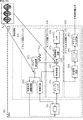
- FIG. 38 is a configuration example of the multi-IMU 200 capable of canceling the flicker noise.
- FIG. 38 shows the configuration of the read circuit 213'' shared by IMU201'-1 and IMU201'-2, which are classified into the same cluster, and the synthesis calculation unit 471'', which constitute the multi-IMU200. Has been done.
- the configurations having the same functions as the multi-IMU200 of FIG. 33 are designated by the same reference numerals, and the description thereof will be omitted.
- the difference between the read circuit 213 and the read circuit 213 is that the differential inversion unit 551 is provided in front of the terminal 512b.
- the differential inversion unit 551 inverts the second phase oscillation signal supplied from the IMU201'-2 and outputs it to the terminal 512b.
- the synthetic calculation unit 471'' is different from the synthetic calculation unit 471' in that the in-cluster synthesis unit 532'is provided in place of the in-cluster synthesis unit 532, and the inversion unit 571 is provided in front of the in-cluster synthesis unit 532'. Is.
- the inversion unit 571 inverts the positive and negative of the angular velocity of the second phase and outputs it to the in-cluster synthesis unit 532.
- the angular velocity of the second layer oscillation signal output from IMU201'-2 is calculated in the state where the first layer oscillation signal output from IMU201'-1 is converted to the reverse phase shift. Will be done.
- the angular velocity obtained in the second phase is set to the angular velocity ⁇ x with respect to the angular velocity x obtained in the first phase.
- the flicker noise is added as n in the read circuit 213, the angular velocity of the first layer is obtained as x + n, and the angular velocity of the second phase is obtained as ⁇ x + n.
- the angular velocity x + n of the first phase is delayed by the delay adjusting unit 531 and supplied to the synthesis unit 532'in the cluster, and the angular velocity -x + n of the second phase is inverted by the inversion unit 571, so that the angular velocity x- It is supplied as n to the synthesis unit 532'in the cluster.
- the in-cluster synthesis unit 532' adds the angular velocity x + n of the first phase and the angular velocity x-n in which the angular velocity of the second phase is inverted and synthesizes them as an average value to obtain the flicker noise component n. It will be possible to cancel.
- step S231 the angular velocity by the first phase IMU201'in the same cluster is measured.
- step S232 the delay adjusting unit 531 of the synthesis calculation unit 471 ′′ temporarily stores the supplied angular velocity of the first phase and delays it until the angular velocity of the second phase is supplied.
- step S233 the differential inversion unit 551 differentially inverts the oscillation signal from the second phase IMU201'in the same cluster and outputs it.
- step S234 the angular velocity by the second phase IMU201'in the same cluster is measured.
- step S235 the inversion unit 571 of the synthesis calculation unit 471 ′′ inverts the positive and negative of the angular velocity of the second phase IMU201 ′ and outputs it to the in-cluster synthesis unit 532.
- step S236 the in-cluster synthesis unit 532'acquires the angular velocity of the first layer supplied from the delay adjusting unit 531 and the angular velocity of the second phase whose positive and negative are reversed, which are supplied from the inversion unit 571, and both are obtained.
- the components are combined in the cluster and output to the resampler 481.
- step S237 the resampler 481 acquires the angular velocity of each cluster, aligns the sampling frequencies of each cluster, and outputs the sampling frequency to the interference removing unit 482.
- step S2308 the interference removing unit 482 removes the influence of the interference and outputs the information of the angular velocity supplied from the resampler 481 to the combining unit 483.
- step S239 the synthesis unit 483 synthesizes the information on the angular velocity of each cluster supplied from the interference removal unit 482 and outputs it as one detection value.
- the normal Alan dispersion of the IMU alone has a waveform as shown by the waveform Wa, whereas the temperature compensation improves the Alan dispersion to the waveform Wsa, for example. Further, it is known that the waveform Wma can be improved by configuring a multi-IMU using a plurality of IMUs.
- the multi-IMU200 has a configuration as shown in FIG. 41.
- IMU201'-1 to 201'-4 are in the same cluster, of which IMU201'-1 is set as the synchronization master device and IMU201'-2 to 201'-4 are.
- This is the configuration when it is set to the synchronous slave device. That is, in this case, the angular velocities from the first phase to the fourth phase are obtained.
- the difference from the multi-IMU200 when the number of time divisions in FIG. 38 is two is that the read circuit 213'''' and the synthesis calculation unit 471'''' are replaced with the read circuit 213'' and the synthesis calculation unit 471''. Is the point provided.
- the difference from the read circuit 213' is that switches 511', 512'are provided in place of the switches 511, 512, and the differential inversion unit 551 is used in place of the differential inversion unit 551. This is the point where -1,551-2 is provided.
- the switches 511'and 512' are basically the same as the switches 511 and 512 in terms of function, but differ in that the number of terminals is set according to the number of time divisions.
- the switch 511' is provided with terminals 511'a to 511'd, and when the angular velocity of the first phase to the fourth phase is required, the switch 511'is correspondingly switched and connected.
- the switch 512' is provided with terminals 512'a to 512'd, and when the angular velocities of the first phase to the fourth phase are required, they are switched and connected accordingly.
- the differential inversion unit 551-1,551-2 basically has the same function as the differential inversion unit 551 in FIG. 38. That is, the differential inversion unit 551-1 differentially inverts the oscillation signal supplied from the second phase IMU201'-2 and outputs it to the terminal 512'b of the switch 512'. Further, the differential inversion unit 551-2 differentially inverts the oscillation signal supplied from the fourth phase IMU201'-4 and outputs the oscillation signal to the terminal 512'd of the switch 512'.
- the difference from the synthesis calculation unit 471'' is that the delay adjustment unit 531-1,531-2 is provided instead of the delay adjustment unit 531 and the inversion unit 571 is replaced with the inversion unit 571.
- the points are that the parts 571-1,571-2 are provided, and the in-cluster synthesis part 532'' is provided in place of the in-cluster synthesis part 532'.
- the delay adjusting units 531-1 and 531-2 all have the same functions as the delay adjusting unit 531.
- the delay adjusting unit 531-1 is supplied with the angular velocity of the first phase and the angular velocity of the second phase. Is temporarily stored up to and output to the in-cluster synthesis unit 532', and the delay adjustment unit 531-2 temporarily stores the angular velocity of the third phase until the angular velocity of the fourth phase is supplied, and synthesizes in the cluster. Output to unit 532'.
- the inversion unit 571-1 inverts the positive and negative of the angular velocity of the second phase and outputs it to the in-cluster synthesis unit 532', and the inversion unit 571-2 inverts the positive and negative of the angular velocity of the fourth phase and in-cluster synthesis unit. Output to 532'.
- the second and fourth phase oscillation signals output from IMU201'-2,201'-4 are the first layer and first layer output from IMU201'-1,201'-3.
- the angular velocity is calculated in a state where the three-phase oscillation signal is converted into the reverse phase shift.
- the positive and negative are inverted by the inversion unit 571-1,571-2, so that the angular velocities of the second phase and the fourth phase are supplied to the in-cluster synthesis unit 532.
- the in-cluster synthesis unit 532'' adds the angular velocities of the first and third phases and the inverted angular velocities of the second and fourth phases and synthesizes them as an average value, whereby the flicker noise component n Can be canceled.
- the mechanical structure may further suppress the occurrence of errors due to beats and detect the angular velocity with higher accuracy.
- the vibrator 211 which is the mechanical configuration of the IMU 201, will be described with reference to FIG. 42.
- the vibrator 211 in FIG. 42 is composed of a proof mass 601, a movable drive unit 602, a fixed drive unit 603, a connection unit 604, and a detection electrode 605.
- the proof mass 601 is a rectangular weight, which is rotated in the R direction of the arrow and vibrated in the Y axis direction with the axis Ax as the rotation axis.
- Movable drive units 602 for vibrating in the Y-axis direction are provided on both side surfaces of the rectangular proof mass 601 in the figure in the Y-axis direction.
- a fixed drive unit 603 is provided at a position facing the movable drive unit 602.
- the movable drive unit 602 consists of electrodes formed in a comb shape toward the opposite side of the proof mass 601 and is movable with respect to the fixed drive unit 603 configured to be fixed to the proof mass 601. It is a composition.
- the fixed drive unit 603 is composed of electrodes formed in a comb shape in a direction facing the proof mass 601, that is, in a direction facing the comb-shaped electrode of the movable drive unit 602, with respect to the connection unit 604. It is formed in a fixed state.
- the movable drive unit 602 and the fixed drive unit 603 are provided with their comb-shaped electrode portions facing each other so as to mesh with each other, so that a capacitance is formed in the space between the two electrodes.
- the electrodes of the movable drive unit 602 and the fixed drive unit 603 are supplied by supplying an oscillation signal having a predetermined drive frequency supplied from the drive circuit block 231 to the electrodes of the fixed drive unit 603.
- the capacitance between them changes according to the drive frequency, and the movable drive unit 602 periodically changes in the Y-axis direction with respect to the fixed drive unit 603 and reciprocates, so that the proof mass at a predetermined drive frequency.
- the 601 is vibrated in the Y-axis direction.
- the proof mass 601 is connected to the connection portion 604 composed of a rectangular frame surrounding the proof mass 601 by the connection portion 601a.
- Plate-shaped electrodes 604a formed in a tree shape are provided on both side surfaces in the X-axis direction of the rectangular frame of the connecting portion 604.
- a plate-shaped detection electrode 605 formed so as to surround and mesh with the plate-shaped electrode 604a formed in a tree shape while not in contact with the electrode 604a is formed, and the electrode 604a and the detection electrode 605 are formed. Capacitance is formed between them.
- the proof mass 601 rotates in the R direction of the arrow about the axis Ax and vibrates in the Y axis direction at a predetermined drive frequency.
- the electrostatic capacitance formed between the electrodes changes due to the change in the distance between the electrodes 604a of the connection portion 604 and the detection electrode 605.
- the Coriolis force can be measured by measuring the change in the capacitance between the electrode 604a of the connection portion 604 and the detection electrode 65.
- the vibration signal supplied from the above-mentioned oscillator 211 to the sense circuit block 232 is a signal indicating a change in capacitance between the electrodes 604a of the connection portion 604 and the detection electrode 65.
- an external force is applied by the proof mass 601 rotating in the R direction of the arrow and reciprocating in the Y-axis direction at a predetermined drive frequency.
- Angular velocity and acceleration are detected based on the Coriolis force that is sometimes detected.
- the IMU 201 in order for the IMU 201 to detect the angular velocity and acceleration with high accuracy, it is a major condition that the proof mass 601 rotates stably and vibrates.
- the multi-IMU200 is supposed to be mounted on a moving body, the operating environment is not always an environment in which the proof mass 601 can be stably rotated and vibrated.
- the vibration frequency changes and a beat is induced in an environment where the above-mentioned proof mass 601 can be stably rotated and cannot be vibrated. As a result, it is expected that the detection accuracy will decrease.
- FIG. 44 is a layout diagram from the upper surface of an IMU unit 610 composed of four IMU 201s capable of canceling an impact in the X-axis direction by devising the vibration direction of the four IMU 201s in the X-axis direction.
- the IMU unit 610 of FIG. 44 is composed of four IMU201-101 to IMU201-104.
- IMU201-102 is provided on the right side of the figure of IMU201-101
- IMU201-103 is provided on the lower side of the figure
- IMU201-104 is provided on the lower right side of the figure. It is provided.
- IMU201-101 and IMU201-102 are connected by a connecting beam 611-1, and the connecting beam 611-1 displaces the displacement between IMU201-101 and IMU201-102 in the opposite phase to the X-axis direction. ..
- the connecting beam 611-1 is a drive mechanism composed of four diamond-shaped frames in the drawing, and the four corner portions 611a-1, 611a-2, 611b-1, and 611b-2 are all included. It has a rotatable configuration, of which the corners 611a-1 in contact with IMU201-101 and the corners 611a-2 in contact with IMU201-102 are connected to IMU201-101 and IMU201-102, respectively.
- connection corners 611a-1 and 611a-2 the corners connected to IMU201-101 and IMU201-102 will be referred to as connection corners 611a-1 and 611a-2, and the other two corners will be referred to as non-connection corners 611b-1, 611b-2. It is called.
- connection corner portions 611a-1 and 611a-2 are widened, and the angle formed by the frame connected to the non-connection angle portions 611b-1 and 611b-2 is narrowed.
- IMU201-101 and IMU201-102 are driven so that they are close to each other.
- the angle formed by the frame connected to the connecting angle portions 611a-1 and 611a-2 is closed so as to be narrowed, and the angle formed by the frame connected to the non-connecting angle portions 611b-1 and 611b-2.
- IMU201-101 and IMU201-102 are driven so as to be separated from each other by opening so as to spread.
- the connecting beam 611-1 Due to the drive mechanism of the connecting corner portions 611a-1, 611a-2 and the non-connecting corner portions 611b-1, 611b-2, the connecting beam 611-1 has the IMU201-101 in the negative direction with respect to the X axis.
- IMU201-102 is set in the positive direction (right direction in the figure) with respect to the X axis so that the distance between IMU201-101 and 201-102 is separated when moving by a predetermined distance (to the left in the figure). Move only the distance.
- the connecting beam 611-1 when the IMU201-101 moves in the positive direction (right direction in the figure) by a predetermined distance with respect to the X axis, the distance between the IMU201-101 and 201-102 approaches.
- IMU201-102 is moved in the negative direction (left direction in the figure) with respect to the X axis by a predetermined distance.
- the connecting beam 611-1 displaces IMU201-101 and IMU201-102 in opposite phases with respect to the X-axis direction, and there is no master-slave between IMU201-101 and IMU201-102. ..
- IMU201-103 and IMU201-104 are connected by a connecting beam 611-2, and the connecting beam 611-2 displaces the displacement between IMU201-103 and IMU201-104 in the opposite phase to the X-axis direction. .. Since the drive mechanism of the connecting beam 611-2 is the same as the drive mechanism of the connecting beam 611-1, detailed illustration and description thereof will be omitted.
- the connecting beam 611-2 is arranged so that when the IMU201-103 moves in the positive direction (right direction in the figure) by a predetermined distance with respect to the X axis, the distance between the IMU201-103 and 201-104 approaches. IMU201-104 is moved in the negative direction (left direction in the figure) with respect to the X axis by a predetermined distance. On the contrary, in the connecting beam 611-2, when the IMU201-103 moves in the negative direction (left direction in the figure) by a predetermined distance with respect to the X axis, the distance between the IMU201-103 and 201-104 is increased. IMU201-104 is moved in the positive direction (right direction in the figure) with respect to the X axis by a predetermined distance.
- the connecting beam 611-2 displaces IMU201-103 and IMU201-104 in opposite phases with respect to the X-axis direction, and there is no master-slave between IMU201-103 and IMU201-104. ..
- IMU201-101 and IMU201-103 are connected by a connecting beam 612-1, and the connecting beam 612-1 displaces the displacement of IMU201-101 and IMU201-103 in the opposite phase to the X-axis direction. ..
- the connecting beam 612-1 is provided with a rotation shaft 612a at the center position, and the IMU201-101 and IMU201-103 can rotate at the ends 612b-1 and 612b-2, respectively. It is connected.
- the connecting beam 612-1 is driven like a seesaw around the rotation shaft 612a in response to the movement of the IMU201-101 and the IMU201-103 in the X-axis direction.
- the connecting beam 612-1 causes the IMU201-103 to move in the negative direction with respect to the X axis (in the negative direction in the figure). Move it by a predetermined distance (to the left in the figure).
- the connecting beam 612-1 moves the IMU201-103 by a predetermined distance in the positive direction with respect to the X axis when the IMU201-101 moves by a predetermined distance in the negative direction with respect to the X axis. ..
- the connecting beam 612-1 displaces IMU201-101 and IMU201-103 in opposite phases with respect to the X-axis direction, and there is no master-slave between IMU201-101 and IMU201-103. ..
- IMU201-102 and IMU201-104 are connected by a connecting beam 612-2, and the connecting beam 612-2 displaces the displacement between IMU201-102 and IMU201-104 in the opposite phase to the X-axis direction. ..
- the drive mechanism of the connecting beam 612-2 is the same as the drive mechanism of the connecting beam 612-1.
- the connecting beam 612-2 causes the IMU201-104 to move in the negative direction with respect to the X axis (in the figure). Move it by a predetermined distance in the middle left direction).
- the connecting beam 612-2 makes the IMU201-104 in the positive direction with respect to the X-axis (on the contrary). Move it by a predetermined distance (to the right in the figure).
- the connecting beam 612-2 displaces IMU201-102 and IMU201-104 in opposite phases with respect to the X-axis direction, and there is no master-slave between IMU201-102 and IMU201-104. ..
- the IMUs 201-101 and 201-104 are driven in the same phase with respect to the X-axis direction, and the IMUs 201-102 and 201-103 are in the same phase with respect to the X-axis direction. Driven, IMU201-101 and 201-104 and IMU201-102 and 201-103 are driven in opposite phase to the X-axis direction.
- the IMUs 201-101 to 201-104 include those having different drive directions with respect to the X-axis direction, but have the same drive frequency as described in the first embodiment to the third embodiment. Is controlled by.
- the detection results of the IMU201s driven in the same phase are added, and the difference between the detection results of the IMU201s driven in the opposite phase is taken to obtain the average value. By doing so, the angular velocity and acceleration are obtained.
- FIG. 45 is a layout diagram from the upper surface of an IMU unit 610 composed of four IMU 201s capable of canceling an impact in the X-axis direction by devising the vibration direction of the four IMU 201s in the Y-axis direction.
- the IMU unit 610 in FIG. 45 is also composed of four IMU201-101 to IMU201-104, like the IMU unit 610 in FIG. 44.
- IMU201-101 and IMU201-102 are connected by a connecting beam 631-1, and the connecting beam 631-1 displaces the displacement of IMU201-101 and IMU201-102 in the opposite phase to the Y-axis direction. ..
- the drive mechanism of the connecting beam 631-1 is the same as that of the connecting beam 612-1 of FIG. 44, but the driving direction is from the X-axis direction to the Y-axis direction.
- the connecting beam 631-1 is centered on the rotation axis 631a when the IMU201-101 connected to the end portion 631b-1 moves in the positive direction (upward direction in the figure) by a predetermined distance with respect to the Y axis.
- IMU201-102 connected to the end 631b-2 is moved in the negative direction (lower direction in the figure) by a predetermined distance with respect to the Y axis.
- the connecting beam 631-1 moves the rotating shaft 631a in the negative direction (lower direction in the figure) by a predetermined distance when the IMU201-101 connected to the end portion 631b-1 moves in the negative direction (lower direction in the figure).
- the IMU201-102 connected to the end 631b-2 is moved in the positive direction (upward in the figure) by a predetermined distance with respect to the Y axis.
- the connecting beam 631-1 displaces IMU201-101 and IMU201-102 in opposite phases with respect to the Y-axis direction, and there is no master-slave between IMU201-101 and IMU201-102. ..
- IMU201-103 and IMU201-104 are connected by a connecting beam 631-2, and the connecting beam 631-2 displaces the displacement between IMU201-103 and IMU201-104 in the opposite phase to the Y-axis direction. ..
- the drive mechanism of the connecting beam 631-2 is the same drive mechanism as that of the connecting beam 632-1.
- the connecting beam 631-2 makes the IMU201-104 in the negative direction with respect to the Y axis (in the figure). Move in the middle-down direction) by a predetermined distance.
- the connecting beam 631-2 makes the IMU201-104 in the positive direction with respect to the Y axis (in the positive direction). Move it by a predetermined distance (upward in the figure).
- the connecting beam 631-2 displaces IMU201-103 and IMU201-104 in opposite phases with respect to the Y-axis direction, and there is no master-slave between IMU201-103 and IMU201-104. ..
- IMU201-101 and IMU201-103 are connected by a connecting beam 632-1, and the connecting beam 632-1 displaces the displacement of IMU201-101 and IMU201-103 in the opposite phase to the Y-axis direction. ..
- the drive mechanism of the connecting beam 632-1 is the same as that of the connecting beam 611-1 in FIG. 44, but the driving direction is from the X-axis direction to the Y-axis direction.
- the connecting beam 632-1 was connected to the connecting angle portions 632a-1 and 632a-2 when the IMU201-101 moved in the positive direction (upward direction in the figure) by a predetermined distance with respect to the Y axis.
- the IMU201-101 and IMU201-103 are mutually connected.
- the IMU 201-103 is moved in the negative direction (lower direction in the figure) with respect to the Y axis by a predetermined distance.
- the connecting beam 632-1 is connected to the connecting angle portions 632a-1 and 632a-2 when the IMU201-101 moves in the negative direction (lower direction in the figure) by a predetermined distance with respect to the Y axis.
- the IMU201-101 and IMU201-103 are configured by opening so that the angle formed by the frame is widened and closing so that the angle formed by the frame connected to the non-connecting corner portions 632b-1 and 632b-2 is narrowed. It is driven so that the distance between them is close to each other, and the IMU 201-103 is moved in the positive direction (upward in the figure) by a predetermined distance with respect to the Y axis.
- the connecting beam 632-1 displaces IMU201-101 and IMU201-103 in opposite phases with respect to the Y-axis direction, and there is no master-slave between IMU201-101 and IMU201-103. ..
- IMU201-102 and IMU201-104 are connected by a connecting beam 632-2, and the connecting beam 632-2 displaces the displacement of IMU201-102 and IMU201-104 in the opposite phase to the Y-axis direction. ..
- the drive mechanism of the connecting beam 632-1 is the same as that of the connecting beam 632-1 of FIG. 44.
- the connecting beam 632-2 causes the IMU201-104 to move in the negative direction with respect to the Y axis (in the figure). Move in the middle-down direction) by a predetermined distance.
- the connecting beam 632-2 makes the IMU201-104 in the positive direction with respect to the Y axis (in the positive direction). Move it by a predetermined distance (upward in the figure).
- the connecting beam 632-2 displaces IMU201-102 and IMU201-104 in opposite phases with respect to the Y-axis direction, and there is no master-slave between IMU201-102 and IMU201-104. ..
- the IMUs 201-101 and 201-104 are driven in the same phase with respect to the Y-axis direction, and the IMUs 201-102 and 201-103 are in the same phase with respect to the Y-axis direction. Driven, IMU201-101 and 201-104 and IMU201-102 and 201-103 are driven in opposite phase to the Y-axis direction.
- the IMUs 201-101 to 201-104 include those having different drive directions with respect to the Y-axis direction, but have the same drive frequency as described in the first embodiment to the third embodiment. Is controlled by.
- the detection results of the IMU201s driven in the same phase are added, and the difference between the detection results of the IMU201s driven in the opposite phase is taken to obtain the average value. By doing so, the angular velocity and acceleration are obtained.
- FIGS. 44 and 45 separately describe the drive mechanism in the X-axis direction and the drive mechanism in the Y-axis direction for the same IMU unit 610, both are provided in the IMU unit 610. It is a driving mechanism.
- the IMU unit 610 uses the difference in the detection results regardless of whether an impact is applied from either the X-axis direction or the Y-axis direction. Since the impact component is canceled in the X-axis direction and the Y-axis direction, it is possible to realize highly accurate measurement of acceleration and angular velocity.
- the multi-IMU200 of FIG. 46 has positive and negative outputs with respect to the X-axis and positive and negative outputs with respect to the Y-axis among the outputs of the IMUs 201-101 to 201-104 of the IMU unit 610 and the IMU unit 610. It is provided with a signal processing unit 651 that receives an output in a direction and executes signal processing.
- the signal processing unit 651 includes arithmetic units 661 and 662, and outputs in the positive and negative directions with respect to the X-axis from IMU201-101 to 201-104, and outputs in the positive and negative directions with respect to the Y-axis. It accepts the output and executes signal processing.
- the calculation unit 661 sets the output in the positive direction in the X-axis direction (X-axis output +) and the output in the negative direction in the X-axis direction (X-axis output-).
- the arithmetic unit 661 divides the difference between the sum of the detection outputs of IMU201-101 and 201-104 and the sum of the detection outputs of IMU201-102 and 201-103 by 2, so that the detection results of the four IMU201s are obtained. By obtaining the average value of, even if there is an impact component in the X-axis direction, it can be appropriately canceled.
- the calculation unit 662 receives the output in the positive direction in the Y-axis direction (Y-axis output +) and the output in the negative direction in the Y-axis direction (Y-axis output-) among the outputs of the IMU unit 610, and mutually receives the output in the Y-axis direction (Y-axis output +).
- the arithmetic unit 662 divides the difference between the sum of the detection outputs of IMU201-101 and 201-104 and the sum of the detection outputs of IMU201-102 and 201-103 by 2, so that the detection results of the four IMU201s are obtained. By obtaining the average value of, even if there is an impact component in the Y-axis direction, it can be appropriately canceled.
- the IMU unit 610 showing the drive mechanism in the X-axis direction is particularly referred to as IMU unit 610X
- the IMU unit 610 showing the drive mechanism in the Y-axis direction is particularly referred to as IMU unit 610Y.
- the IMU unit 610 is composed of four IMU201-101 to IMU201-104.
- step S301 the calculation unit 661 receives the output in the positive direction in the X-axis direction (X-axis output +) and the output in the negative direction in the X-axis direction (X-axis output-) among the outputs of the IMU unit 610. Then, the average value is obtained from the mutual difference and output as the collior force of the X axis.
- the arithmetic unit 661 has four units, for example, by dividing the difference between the sum of the detection outputs of IMU201-101 and 201-104 and the sum of the detection outputs of IMU201-102 and 201-103 by 2.
- the average value of the detection results of IMU201 is obtained as the Coriolis output in which the impact component in the X-axis direction is canceled.
- step S302 the calculation unit 662 receives the output in the positive direction in the Y-axis direction (Y-axis output +) and the output in the negative direction in the Y-axis direction (Y-axis output-) among the outputs of the IMU unit 610. Then, the difference between them is obtained, the average value is obtained, and it is output as the colliorative force of the Y axis.
- the arithmetic unit 662 has four units, for example, by dividing the difference between the sum of the detection outputs of IMU201-101 and 201-104 and the sum of the detection outputs of IMU201-102 and 201-103 by 2.
- the average value of the detection results of IMU201 is obtained as the Coriolis output in the Y-axis direction in which the impact component in the Y-axis direction is canceled.
- the X-axis is calculated by using the difference between the detection output of IMU201-101 and 201-104 and the detection output of IMU201-102 and 201-103 in both the X-axis direction and the Y-axis direction. It is possible to appropriately cancel any impact component in either the directional direction or the Y-axis direction.
- FIG. 48 is a configuration example of a multi-IMU 200 capable of canceling an impact in the X-axis direction when the IMU block 610B is configured by arranging four IMU units 610 in 2 ⁇ 2.
- the IMU block 610B in FIG. 48 is composed of IMU units 610-1 to 610-4. Since the IMU block 610B in FIG. 48 shows the drive mechanism in the X-axis direction of the IMU units 610-1 to 610-4, the IMU block 610B and the IMU unit 610-1 are shown in the figure. To 610-4 are described as IMU block 610BX and IMU unit 610X-1 to 610X-4, respectively.
- the IMU block 610BX of FIG. 48 since four IMU units 610 each having four IMU 201s are provided, the IMU block 610BX is composed of a total of 16 IMU 201s, four each in the horizontal direction and the vertical direction. ing.
- the drive mechanism in the X-axis direction of the IMU 201 constituting each of the IMU units 610X-1 to 610X-4 is the same as the configuration described with reference to FIG. 44.
- connecting beam 612E-1 connecting the IMU201-103-1 at the lower left of the IMU unit 610X-1 and the IMU201-101-3 at the upper left of the 610X-3, and the IMU201 at the lower right of the IMU unit 610X-2.
- a connecting beam 612E-2 connecting ⁇ 104-2 and IMU201-102-4 on the upper right of 610X-4 is newly provided.
- connecting beams 611E-1 and 611E-2 connecting horizontally adjacent IMU201s are provided.
- Two are provided on the upper and lower sides, and connecting beams 611E-3 and 611E-4 are similarly provided at the connection portions between the IMU unit 610X-3 and the IMU unit 610X-4. That is, in the multi-IMU 200 of FIG. 48, four connecting beams 611E-1 to 611E-4 surrounded by the alternate long and short dash line are newly provided.
- the connecting beam 612E-1 has the same drive mechanism as the connecting beam 612-1 of FIG. 44, and the connecting beam 612E-2 has the same driving mechanism as the connecting beam 612-2 of FIG. 44.
- a total of 16 IMU 201s, 4 in each of the horizontal direction and the vertical direction constituting the multi-IMU 200 in FIG. 48, are all driven at the same drive frequency and are adjacent to each other in the horizontal direction and the vertical direction.
- the IMU 201 is driven in the opposite phase to the X-axis direction, and the IMU 201 adjacent to each of the diagonally upper left direction, the diagonally lower left direction, the diagonally upper right direction, and the diagonally lower right direction is in the X-axis direction. Drive in phase.
- the detection results of the IMU201s driven in the same phase are added to each other among the constituent IMU201s, and the detection results of the IMU201s driven in the opposite phase are added to each other.
- the angular velocity and acceleration are obtained by taking the difference between the two and obtaining the average value.
- the impact component in the X-axis direction can be determined by taking the difference between the detection results of the IMU201 driven in the opposite phase in the X-axis direction. Since it will be canceled, it is possible to suppress the influence of the impact.
- the angular velocity and the acceleration can be detected with higher accuracy by increasing the number of IMU201s used for the multi-IMU200 of FIG. 44.
- FIG. 49 is a configuration example of the IMU block 610B capable of canceling the impact in the Y-axis direction when the four IMU units 610 are arranged in 2 ⁇ 2.
- the IMU block 610B in FIG. 49 is composed of IMU units 610-1 to 610-4. Since FIG. 49 shows the drive mechanisms of the IMU units 610-1 to 610-4 in the Y-axis direction, the IMU block 610B and the IMU units 610-1 to 610-4 are shown in the figure. , IMU block 610BY and IMU units 610Y-1 to 610Y-4, respectively.
- the IMU block 610BY of FIG. 49 since four IMU units 610 each having four IMU 201s are provided, the IMU block 610 BY is composed of a total of 16 IMU 201s, four each in the horizontal direction and the vertical direction. ing.
- the drive mechanism in the Y-axis direction of the IMU 201 constituting each of the IMU units 610Y-1 to 610Y-4 is the same as the configuration described with reference to FIG. 45.
- connecting beam 631E-1 connecting the IMU201-102-1 on the upper right of the IMU unit 610Y-1 and the IMU201-101-2 on the upper left of the 610Y-2, and the IMU201 on the lower right of the IMU unit 610Y-3.
- a connecting beam 631E-2 for connecting ⁇ 103-3 and IMU201 at the lower left of 610Y-4 is newly provided.
- connecting beams 632E-1 and 632E-2 connecting vertically adjacent IMU201s are provided.
- the connecting beams 632E-3 and 632E-4 are also provided at the connection portions between the IMU unit 610Y-2 and the IMU unit 610Y-4. That is, four connecting beams 632E-1 to 632E-4 surrounded by the alternate long and short dash line are newly provided.
- the connecting beam 631E-1 has the same drive mechanism as the connecting beam 631-1 in FIG. 45, and the connecting beam 631E-2 has the same driving mechanism as the connecting beam 631-2 in FIG. 45.
- a total of 16 IMU 201s, 4 in each of the horizontal direction and the vertical direction constituting the IMU block 610BY in FIG. 49, are all driven at the synchronized drive frequencies, and are driven in the horizontal direction and the vertical direction, respectively. It is driven in the opposite phase to the Y-axis direction with the adjacent IMU201, and with respect to the Y-axis direction, which is adjacent to each of the diagonally upper left direction, the diagonally lower left direction, the diagonally upper right direction, and the diagonally lower right direction. And drive in the same phase.
- the detection results of the IMU201s driven in the same phase are added to each other among the constituent IMU201s, and the detection results of the IMU201s driven in the opposite phase are added to each other.
- the angular velocity and acceleration are obtained by taking the difference between the two and obtaining the average value.
- the impact component in the Y-axis direction can be determined by taking the difference between the detection results of the IMU201 driven in the opposite phase in the Y-axis direction. Since it will be canceled, it is possible to suppress the influence of the impact.
- the angular velocity and the acceleration can be detected with higher accuracy by increasing the number of IMU201s used for the multi-IMU200 of FIG. 45.
- the signal processing in the multi-IMU 200 of FIGS. 48 and 49 can be realized by providing the signal processing unit 651 of FIG. 46 for each IMU unit 610 and performing the signal processing described with reference to the flowchart of FIG. 47. It is possible.
- Second variant of the fourth embodiment >> In the above, an example of realizing a multi-IMU200 by providing four IMU units 610 and using the signal processing results of each IMU unit 610 has been described, but the detection results of each of the four IMU units 610 have been described. May be time-divisioned by switching between channels and outputting.
- FIG. 50 shows a configuration example of a multi-IMU 200 in which the detection results of each of the four IMU units 610 are time-division-processed as output signals of four channels.
- the multi-IMU 200 of FIG. 50 is composed of an IMU block 610B, a signal processing unit 671, and a switching unit 672.
- the drive mechanism of the IMU block 610B includes a drive mechanism in the X-axis direction indicated by the IMU block 610BX and a drive mechanism in the Y-axis direction indicated by the IMU block 610BY.
- the IMU block 610BX is composed of IMU units 610X-101 to 610X-4.
- each of the IMU units 610X-1 to 610X-4 outputs the detection output as a signal of channels 1 to 4.
- the IMU unit 610X-1 outputs a positive output in the X-axis direction (X-axis output ch1 +) and an output in the negative direction in the X-axis direction (X-axis output ch1-) as channel 1 (ch1). ..
- the IMU unit 610X-2 outputs a positive output in the X-axis direction (X-axis output ch2 +) and a negative output in the X-axis direction (X-axis output ch2-) as channel 2 (ch2).
- the IMU unit 610X-3 outputs a positive output in the X-axis direction (X-axis output ch3 +) and a negative output in the X-axis direction (X-axis output ch3-) as channel 3 (ch3).
- the IMU unit 610X-4 outputs a positive output in the X-axis direction (X-axis output ch4 +) and a negative output in the X-axis direction (X-axis output ch4-) as channel 4 (ch4).
- the IMU block 610BY is composed of IMU units 610Y-1 to 610Y-4.
- Each of the IMU units 610Y-1 to 610Y-4 outputs the detection output as a signal of channels 1 to 4.
- the IMU unit 610Y-1 has a positive output in the Y-axis direction (Y-axis output ch1 +) and a negative output in the Y-axis direction (Y-axis output ch1-) as channel 1 (ch1). Is output to the signal processing unit 671.
- the IMU unit 610Y-2 has a signal processing unit 671 that outputs in the positive direction in the Y-axis direction (Y-axis output ch2 +) and the output in the negative direction in the Y-axis direction (Y-axis output ch2-) as channel 2 (ch2). Output to.
- the IMU unit 610Y-3 uses signal processing unit 671 as channel 3 (ch3) to output in the positive direction in the Y-axis direction (Y-axis output ch3 +) and output in the negative direction in the Y-axis direction (Y-axis output ch3-). Output to.
- the IMU unit 610Y-4 outputs the positive direction (Y-axis output ch4 +) in the Y-axis direction and the output in the negative direction (Y-axis output ch4-) in the Y-axis direction as channel 4 (ch4) as a signal processing unit 671. Output to.
- the signal processing unit 671 includes arithmetic units 681-1 to 681-4, each of which receives outputs of channels 1 to 4 in the positive and negative directions with respect to the X axis from the IMU block BX and performs signal processing. Run.
- the arithmetic unit 681-1 outputs the positive direction (X-axis output ch1 +) of the channel 1 (ch1) in the X-axis direction and the output in the negative direction in the X-axis direction. (X-axis output ch1-) is received, the mutual difference is obtained, the average value is obtained, and the result is output to the switching unit 672 as the X-axis collior force (ch1).
- the arithmetic unit 681-2 has a positive output (X-axis output ch2 +) in the X-axis direction of channel 2 (ch2) and a negative output (X-axis output ch2) in the X-axis direction. -) Is accepted, the difference between them is obtained, the average value is obtained, and it is output to the switching unit 672 as the colliorative force (ch2) of the X axis.
- the calculation unit 681-3 has a positive output (X-axis output ch3 +) in the X-axis direction of channel 3 (ch3) and a negative output (X-axis output ch3) in the X-axis direction. -) Is accepted, the difference between them is obtained, the average value is obtained, and it is output to the switching unit 672 as the colliorative force (ch3) of the X axis.
- the calculation unit 681-4 has a positive output (X-axis output ch4 +) in the X-axis direction of channel 4 (ch4) and a negative output (X-axis output ch4) in the X-axis direction. -) Is accepted, the difference between them is obtained, the average value is obtained, and it is output to the switching unit 672 as the colliorative force (ch4) of the X axis.
- the switching unit 672 outputs the Coriolis force of the 4-channel X-axis supplied from the signal processing unit 671 to the subsequent stage in time division.
- the switching unit 672 includes terminals 672a-1 to 672a-4, a switch 672b, and a control unit 672c.
- Terminals 672a-1 to 672a-4 receive the output of the X-axis Coriolis force of channels 1 to 4 from the signal processing unit 671, respectively.
- the switch 672b is controlled by the control unit 672c, and the connection with the terminals 672a-1 to 672a-4 is switched and connected at predetermined time intervals, so that the Coriolis force of the X-axis of 4 channels is time-divisioned to the subsequent stage. Output.
- a signal processing unit that receives and processes signals from the IMU block 610BY in the Y-axis direction in the positive direction of 4 channels and the output of 4 channels in the negative direction in the Y-axis direction. Also provided is a switching unit that outputs the output of the colliorative force in the Y-axis direction for four channels of the signal processing unit in a time-divided manner in the subsequent stage.
- step S321 the control unit 672c of the switching unit 672 initializes the counter n for counting channels to 1.
- step S322 the control unit 672c controls the switch 672b based on the counter n and connects to the terminal 672bn.
- step S323 the calculation units 681-1 to 681-4 of the signal processing unit 651 calculate the Coriolis force in the X-axis direction of the channels 1 to 4, respectively, and output them to the switching unit 672.
- step S324 the switching unit 672 outputs the Coriolis force in the X-axis direction of the channel n supplied from the signal processing unit 671 via the terminal 672bn to which the switch 672b is connected.
- step S325 the control unit 672c determines whether or not the counter n is 4, and if not, the process proceeds to step S326.
- step S326 the control unit 672c increments the counter n by 1, and the process returns to step S322.
- the channel n is sequentially switched by 1, and the Coriolis force in the X-axis direction of the corresponding channel is switched and output to the subsequent stage.
- step S325 when the counter n is considered to be 4, the process proceeds to step S327.
- step S327 the control unit 672c determines whether or not the end of the process is instructed, and if the end is not instructed, the process returns to step S321 and the subsequent processes are repeated.
- the channel is switched from 1 to 4 until the end of processing is instructed, and the Coriolis force in the X-axis direction of the corresponding channel continues to be output.
- step S327 the process ends.
- the Coriolis force in each X-axis direction corresponding to the IMU unit 610 divided into 4 channels is sequentially switched and output to the subsequent stage, which is necessary for the detection of the subsequent stage corresponding to each channel. It is possible to simplify the configuration to be 1/4.
- FIG. 52 shows the configuration of the IMU block 610B of the multi-IMU200 that can cancel the impact in the Z-axis direction.
- the IMU block 610B in FIG. 52 is composed of IMU units 610-1 to 610-4. Since the IMU block 610B in FIG. 52 shows the drive mechanism of the IMU units 610-1 to 610-4 in the Z-axis direction, the IMU block 610B and the IMU unit 610-1 are shown in the figure. 610-4 are described as IMU block 610BZ and IMU unit 610Z-1 to 610Z-4, respectively.
- IMU block 610BZ of FIG. 52 since four units consisting of IMU units 610Z-1 to 610Z-4 each having four IMUs 201-101 to 104 are provided, they are provided in the horizontal direction and the vertical direction, respectively. It is composed of 16 IMU201s, 4 each.
- the IMU unit 610Z-1 includes IMU201-101-1 to IMU201-104-1
- the IMU unit 610Z-2 includes IMU201-101-2 to IMU201-104-14-.
- the IMU unit 610Z-3 includes IMU201-101-3 to IMU201-104-3
- the IMU unit 610Z-4 includes IMU201-101-4 to IMU201-104-4. There is.
- the IMU201 marked with a cross indicates the state of being moved to the back side with respect to the paper surface which is the base position
- the IMU201 marked with a black circle is the base. It shows the state of being moved to the front side with respect to the paper surface which is the position.
- the left side shows the side cross section of the H2 and H4 rows of the IMU block 610BZ as seen from the X-axis direction on the right side of the figure
- the right side shows the H1 row of the IMU block 610BZ
- H3th column shows the side cross section seen from the X-axis direction on the right side in the figure.
- the upper row shows the side cross section of the IMU block 610BZ in the B row and the D row as viewed from the lower Y-axis direction in the figure
- the lower row shows the A row of the IMU block 610BZ.
- the cross section of the side surface of the C-th row as viewed from the lower Y-axis direction in the figure is shown.
- the four vertical rows in the figure of the 16 IMU 201s constituting the IMU block 610BZ in the upper left of FIG. 52 are represented by the four rows A to D, and the four horizontal columns are H1. It is expressed in the columns to the H4 column.
- the Ath line is composed of IMU201-101-1, IMU201-102-1, IMU201-101-2, and IMU201-102-2 from the left in the figure. , Are connected by connecting beams 701-1 to 701-3, respectively.
- the connecting beam 701-1 is composed of a frame or the like, and the central axis 701a-1 is fixed to the base position Lb, and IMU201-101 adjacent to both ends 701b-1-1 and 701b-1-2, respectively. -1,201-102-1 is connected.
- the IMU201-101-1 connected to one end portion 701b-1-1 is in the negative direction (for example, the base position Lb) by a predetermined distance with respect to the Z-axis direction.
- the IMU 201 rotates about the central axis 701a-1 and is connected to the other end 701b-1-2.
- -102-1 is moved in the positive direction by a predetermined distance with respect to the Z-axis direction (for example, the front side (in the lower left of FIG. 52, the upper part in the drawing) with respect to the paper surface at the base position Lb).
- the IMU201-101-1 connected to one end 701b-1-1 is in the positive direction (for example, at the base position Lb) by a predetermined distance with respect to the Z-axis direction.
- the IMU201-102-1 moves to the negative direction by a predetermined distance with respect to the Z-axis direction (for example, the back side of the paper surface at the base position Lb (in the lower left of FIG. 52, the lower part in the drawing)). ..
- the IMU201-101-1, IMU201-102-1, IMU201-101-2, and IMU201-102-2 constituting the Ath row are the IMU201- by the drive mechanism of the connecting beams 701-1 to 701-3.
- 101-1 and IMU201-102-1 are driven in phase in synchronization with respect to the positive or negative direction in the Z-axis direction
- IMU201-101-2 and IMU201-102-2 are positive or negative in the Z-axis direction. It is driven in the same phase in synchronization with the direction of.
- IMU201-101-1 and IMU201-102-1 and IMU201-101-2 and IMU201-102-2 are driven so as to be in opposite phase in synchronization with the Z-axis direction.
- the IMU201-101-1, IMU201-103-1, IMU201-101-3, and IMU201-103-3 constituting the H1 row are connected beams 702-. It is connected by 1 to 702-3.
- the connecting beam 702-1 is composed of a frame or the like, and the central axis 702a-1 is fixed to the base position Lb, and IMU201-101 adjacent to each of both ends 702b-1-1 and 702b-1-2. -1,201-103-1 is connected.
- the IMU201-101-1 connected to one end portion 702b-1-1 is in the negative direction (for example, the base position Lb) by a predetermined distance with respect to the Z-axis direction.
- the IMU 201-103-1 is positively oriented by a predetermined distance with respect to the Z-axis direction (for example, on the front side with respect to the paper surface at the base position Lb, that is, in the upper right portion of FIG. 52, with respect to the base position Lb. To the left).
- the IMU201-101-1 connected to one end 702b-1-1 is in the positive direction (for example, at the base position Lb) by a predetermined distance with respect to the Z-axis direction.
- the IMU201-103-1 is placed in the negative direction by a predetermined distance with respect to the Z-axis direction (for example, on the back side with respect to the paper surface which is the base position Lb, that is, in the upper right portion of FIG. 52, at the base position Lb.
- move it to the left side moves to the left side.
- IMU201-101-1, IMU201-103-1, IMU201-101-3, IMU201-103-3 in the H1 row are IMU201-101- by the drive mechanism of the connecting beams 702-1 to 702-3.
- IMU201-101-3 are driven synchronously in the positive or negative direction in the Z-axis direction
- IMU201-103-1 and IMU201-103-3 are driven in the positive or negative direction in the Z-axis direction. Drive in synchronization and in phase.
- IMU201-101-1 and IMU201-101-3 and IMU201-103-1 and IMU201-103-3 are driven so as to be in opposite phase in synchronization with the Z-axis direction.
- the IMU201 constituting each of the Ath row to the Dth row is also configured by the same drive mechanism as the IMU201 in the Ath row. Therefore, as shown in the upper part of the lower left of FIG. 52, the IMU201s on the Bth and Dth rows are driven in the opposite phase to the IMU201 on the Ath row in the Z-axis direction, and the Cth row is driven. As shown in the lower left part of FIG. 52, the IMU201 is driven in the same phase as the IMU201 in the A row in the Z-axis direction.
- the IMUs constituting each of the H1st row to the H4th row are also configured by the same drive mechanism as the IMU201 in the H1st row. Therefore, as shown on the left side of the upper right part of FIG. 52, the IMU201s in the H2 and H4 rows are driven in opposite phases to the IMU201s in the H1 row in the Z-axis direction, and are driven in the opposite phase to the H3 row. As shown on the right side of the upper right portion of FIG. 52, the IMU 201 is driven in the same phase as the IMU 201 in the H1 row in the Z-axis direction.
- the adjacent IMU 201s arranged in the X-axis direction on the A to D rows constituting the IMU block 610BZ are alternately driven in the opposite phase with the base position Lb as the center in the Z-axis direction. .. Further, the adjacent IMU 201s arranged in the Y-axis direction in the H1st row to the H4th row are alternately driven in the opposite phase with the base position Lb as the center in the Z-axis direction.
- each IMU 201 constituting the IMU block 610BZ is driven in the opposite phase in the Z-axis direction in synchronization with the vertically adjacent IMU 201 and the horizontally adjacent IMU 201, respectively, and is driven diagonally upward to the left, diagonally downward to the left, and to the right. It is driven in the same phase in the Z-axis direction with the IMU 201 adjacent diagonally upward and diagonally downward to the right.
- FIG. 52 shows the IMU 201-101-1 in the negative direction by a predetermined distance with respect to the Z-axis direction (for example, on the back side with respect to the paper surface at the base position Lb, that is, at the base position Lb in the upper right portion of FIG. 52.
- IMU201-101-1 is positively oriented by a predetermined distance with respect to the Z-axis direction (for example, on the front side with respect to the paper surface at the base position Lb, that is, with respect to the base position Lb in the upper right portion of FIG. 52.
- the drive direction of each IMU 201 in FIG. 52 in the Z-axis direction changes in the opposite direction.
- the IMUs 201-103-1, 201-104-1, 201-1032, 201-104-2 are connected by connecting beams 701-201 to 701-203.
- the central portion of the side surface of each IMU 201 may be connected to the respective ends of the connecting beams 701-201 to 701-203.
- IMU201-103-1, 201-104-1, 201-103-2, 201-104-2 are connected by connecting beams 701-301 to 701-303.
- the center position of each IMU 201 and the respective ends of the connecting beams 701-301 to 701-303 may be connected to each other.
- the IMU201 is viewed from above in order to avoid the interference related to the driving of the connecting beam 701. At that time, it may be H-shaped so as to avoid interference related to driving the connecting beam 701.
- the signal processing for obtaining the Coriolis force in the Z-axis direction is the same as the signal processing for obtaining the Coriolis force in the X-axis direction described with reference to the flowchart of FIG. 51, and thus the description thereof will be omitted. ..
- FIG. 55 shows a configuration example of a multi-IMU 200 in which signal processing is performed after switching the output channel for each IMU unit 610.
- the same reference numerals are given to the configurations having the same functions as the configurations of the multi-IMU200 of FIG. 50, and the description thereof will be omitted.
- the multi-IMU200 of FIG. 55 differs from the multi-IMU200 of FIG. 50 in that it includes a switching unit 731, 732 and a signal processing unit 733 instead of the signal processing unit 671 and the switching unit 672.
- the switching unit 731 is composed of terminals 731a-1 to 731a-4, a switch 731b, and a control unit 731c.
- Terminals 731a-1 to 731a-4 receive the output of the positive Coriolis force in the X-axis direction of channels 1 to 4, which are the outputs of the IMU units 610X-1 to 610X-4 of the IMU block 610BX, respectively.
- the switch 731b is controlled by the control unit 731c in synchronization with the switching unit 732, sequentially switched and connected to the terminals 731a-1 to 731a-4, and is the output of the IMU units 610X-1 to 610X-4.
- the output of the Coriolis force in the positive direction in the X-axis direction of 4 to 4 is output to the signal processing unit 733.
- the switching unit 732 is composed of terminals 732a-1 to 732a-4, a switch 732b, and a control unit 732c.
- Terminals 732a-1 to 732a-4 receive the output of the negative Coriolis force in the X-axis direction of channels 1 to 4, which are the outputs of the IMU units 610X-1 to 610X-4 of the IMU block 610BX, respectively.
- the switch 732b is controlled by the control unit 732c in synchronization with the switching unit 731, sequentially switched and connected to the terminals 732a-1 to 732a-4, and is the output of the IMU units 610X-1 to 610X-4.
- the output of the Coriolis force in the negative direction in the X-axis direction of 4 to 4 is output to the signal processing unit 733.
- the signal processing unit 733 includes a calculation unit 741 and controls the calculation unit 741 to switch channels synchronously from the switching units 731 and 732 and supply the channels 1 to 4 in the positive direction in the X-axis direction.
- the choriori force of each channel is calculated and output based on the difference between the choriori force of and the choriori force in the negative direction.
- the channels are switched in synchronization with each other, so that the calculation unit 741 sequentially switches the channels from the switching units 731 and 732 and supplies them in the positive Coriolis force in the X-axis direction.
- the Coriolis force of each channel is calculated based on the difference between the Coriolis force in the negative direction and the Coriolis force in the negative direction.
- the channel is switched, signal processing is performed, the channel is switched, and the positive and negative Coriolis force is calculated, so that it is required for the arithmetic processing in the subsequent stage from the IMU block 610BX. It is possible to simplify the configuration to two and reduce flicker noise.
- the configuration in the Z-axis direction may be provided in the same manner.
- step S381 the control units 731c and 732c of the switching units 731 and 732 initialize the counter n for counting channels to 1 in synchronization with each other.
- step S382 the control unit 731c controls the switch 731b based on the counter n and connects to the terminals 731a-n.
- step S383 the control unit 732c controls the switch 732b based on the counter n and connects to the terminal 732a-n.
- step S384 the switch 731b of the switching unit 731 supplies the signal processing unit 733 with a positive collioring force in the X-axis direction of the channel n supplied to the terminals 731a-n, and the switch 732b of the switching unit 732 causes the switch 732b of the switching unit 732 to supply the signal processing unit 733.
- the collior force in the negative direction of the channel n supplied to the terminals 732a-n in the X-axis direction is supplied to the signal processing unit 733.
- step S385 the calculation unit 741 of the signal processing unit 733 has a positive Coriolis force in the X-axis direction of the channel n supplied from the switching unit 731 and a negative Coriolis force in the X-axis direction of the channel n supplied from the switching unit 732. Based on the Coriolis force in the direction, the Coriolis force in the X-axis direction is calculated and output so that the impact is canceled.
- step S386 the control units 731c and 732c of the switching units 731 and 732 determine whether or not the counter n is 4, and if not, the process proceeds to step S387.
- step S387 the control units 731c and 732c of the switching units 731 and 732 increment the counter n by 1, and the process returns to step S382.
- the channel n is sequentially switched by 1, and the Coriolis force of the corresponding channel n is switched and output to the signal processing unit 733.
- step S387 when the counter n is considered to be 4, the process proceeds to step S388.
- step S388 the control units 731c and 732c of the switching units 731 and 732 determine whether or not the end of the process is instructed, and if the end is not instructed, the process returns to step S381 and the subsequent processes. Is repeated.
- the channels are cyclically switched from 1 to 4 until the end of processing is instructed, and the Coriolis force in the X-axis direction of the corresponding channel continues to be output.
- step S388 the process ends.
- the positive and negative Coriolis forces in the X-axis direction corresponding to the IMU unit 610 divided into four channels are sequentially switched and output to the signal processing unit 733, so that they are output to each channel. It is possible to simplify the configuration required for the corresponding detection in the subsequent stage to 1/2.
- the channel is switched and the positive and negative Coriolis forces in the X-axis direction are output to the signal processing unit 733, so that flicker noise can be reduced.
- the Coriolis force in the Y-axis direction and the Coriolis force in the Z-axis direction are obtained by performing the same processing, but the description is omitted because the processing is basically the same except for the axial direction. do.
- the IMU unit 610 may be composed of 4 ⁇ 4 units, for a total of 16 units.
- FIG. 57 shows a configuration example of an IMU block 610BXn in which 4 ⁇ 4 IMU units 610X including a drive mechanism for canceling an impact in the X-axis direction are arranged.
- FIG. 58 shows a configuration example of an IMU block 610BYn in which 4 ⁇ 4 IMU units 610Y including a drive mechanism for canceling an impact in the Y-axis direction are arranged.
- FIG. 59 shows a configuration example of the IMU block 610BZn in which 4 ⁇ 4 IMU units 610Z including a drive mechanism for canceling an impact in the Z-axis direction are arranged.
- the number of IMU units 610 is not limited to 16, and may be any other number, for example, n. Further, the number in the horizontal direction and the number in the vertical direction do not have to be the same.
- the configuration of the multi-IMU200 including the IMU block 610Bn composed of the IMU blocks 610BXn, 610BYn, and 610BZn relating to the n IMU units by expanding the drive mechanism for canceling the impact in the XYZ axis direction of FIGS. 57 to 59 is shown in FIG. As shown by 60, it is basically the same as the configuration of the multi-IMU 200 of FIG.
- the multi-IMU 200 of FIG. 60 includes an IMU block 610Bn, a signal processing unit 751, and a switching unit 752.
- IMU block 610Bn the configuration that realizes the signal processing corresponding to the drive mechanism that cancels the impact in the X-axis direction is shown, but the signal processing unit in the Y-axis direction and the Z-axis direction (not shown). It also has a switching unit.
- the IMU block 610Bn outputs a positive Coriolis force in the X-axis direction and a negative Coriolis force for each channel with the IMU unit 610 as a unit. That is, here, the channels are n channels corresponding to the number of units n of the IMU unit 610.
- the signal processing unit 751 includes calculation units 761-1 to 761-n, calculates the Coriolis force of each channel, and outputs the calculation to the switching unit 752.
- the switching unit 752 outputs the Coriolis force of the n-channel X-axis supplied from the signal processing unit 751 to the subsequent stage in time division.
- the switching unit 752 includes terminals 752a-1 to 752an, a switch 752b, and a control unit 752c.
- the terminals 752a-1 to 752a-n each receive the output of the X-axis Coriolis force of the channel n from the signal processing unit 751.
- the switch 752b is controlled by the control unit 752c, and the connection with the terminals 752a-1 to 752a-n is switched and connected at predetermined time intervals, so that the Coriolis force of the n-channel X-axis is time-divisioned to the subsequent stage. Output.
- the signal processing of the multi-IMU200 of FIG. 60 is the processing when the processing described with reference to FIG. 51 becomes n channels, and therefore the description thereof will be omitted.
- the signal processing may be performed after the channel is switched, as in the case of the multi-IMU 200 described with reference to FIG. 55.
- the IMU 201 is an IMU unit 610 whose minimum unit is 2 ⁇ 2 in the horizontal direction and the vertical direction has been described, but the IMU unit 610 is configured by the number other than that.
- an IMU unit 610 having 4 ⁇ 4 IMU 201s as a unit may be formed.
- 16 IMU 201s may form one channel so that signal processing is performed.
- the number of IMU201s constituting the IMU unit 610 that constitutes each channel it is desirable that the number of IMU201s that detect the Coriolis force in the positive direction and the number of IMU201s that detect the Coriolis force in the negative direction are the same.
- the IMU201 for detecting the Coriolis force in the positive direction and the IMU201 for detecting the Coriolis force in the negative direction do not necessarily have to be the same number. Is required.
- the representative value of the positive Coriolis force is obtained from the detection results of a plurality of IMU201s that detect the positive Coriolis force
- the representative value of the negative Coriolis force is obtained from the detection results of the plurality of IMU201s that detect the negative Coriolis force.
- the value is obtained, and the Coriolis force of the IMU unit 610 for one channel is obtained so that the impact is canceled based on the difference between the representative value of the positive Coriolis force and the representative value of the negative Coriolis force. You may do so.
- FIG. 61 shows a configuration example when a multi-IMU 200 equipped with a drive mechanism capable of canceling an impact in the XYZ axis direction is applied to an image sensor.
- a multi-IMU 200 equipped with a drive mechanism capable of canceling the above-mentioned impact in the XYZ axis direction is attached to the back side of the image pickup surface of the image sensor 801. There is.
- the multi-IMU200 is composed of n IMU units 610 provided with IMU blocks 610BXn, 610Y, and 610BXn, which are drive mechanisms that can cancel each impact in the XYZ axial directions.
- the camera shake represents the shake of the image pickup that occurs when the user grips and operates the image pickup device by hand, but here, it represents the whole shake that occurs during the image pickup. For this reason, for example, with respect to an image pickup device mounted on a moving body device such as a drone or a vehicle driven by a motor or an engine, camera shake also occurs in the image pickup caused by high-frequency vibration generated by the drive of the motor or engine. It shall be included in.
- FIG. 62 is a configuration example of an image pickup device that realizes image stabilization by driving an optical block.
- the image pickup apparatus 1001 of FIG. 62 is composed of an optical block 1011, a reflector plate 1012, a shutter 1013, an image sensor 1014, and a drive unit 1015.
- the optical block 1011 is composed of a lens for adjusting the focus and the like, and transmits the incident light shown by the solid line to focus on the image sensor 1014 through the reflector plate 1012 and the shutter 1013.
- the incident light chorused on the image sensor 1014 is represented by a dotted line.
- the wavy portion in the transmission path of the incident light of the solid line expresses camera shake.
- the reflector plate 1012 together with a mirror (not shown), reflects a part of the incident light to the finder F that the user looks into, and transmits the other incident light to the image sensor 1014 via the shutter 1013.
- the shutter 1013 has a mechanical configuration or an electrical configuration for controlling opening and closing, and adjusts the exposure time of light transmitted through the optical block 1011 and incident light to the image sensor 1014. do.
- the image sensor 1014 is composed of CMOS, CCD, or the like, and captures an image composed of pixel signals according to the amount of incident light.
- the drive unit 1015 is composed of an actuator or the like, and drives the optical block 1011 in the direction perpendicular to the incident direction of the incident light.
- the drive unit 1015 drives the optical block 1011 so as to cancel the detected motion.
- the optical block 1011 is driven by the drive unit 1015 so as to cancel the movement caused by the camera shake or the like, so that the camera shake of the image captured by the image sensor 1014 is corrected. ..
- the solid line indicating the path of the incident light after the drive unit 1015 is a straight line, which means that the camera shake of the incident light is corrected by the operation of the drive unit 1015. There is.
- the drive unit 1015 in the image pickup apparatus 1001 of FIG. 62 needs to drive the optical block 1011 made of a lens or the like, a relatively large configuration is required. Further, since the drive unit 1015 has a relatively large configuration, it is difficult to drive at high speed. For example, the drive unit 1015 is driven by following the high frequency vibration generated when the motor or the engine is operated, and cancels the vibration. Is difficult to achieve.
- FIG. 63 is a configuration example of an image pickup device in which a drive unit for driving the image sensor 1014 is provided to realize image stabilization.
- the same reference numerals are given to the configurations having the same functions as the image pickup apparatus 1001 of FIG. 62, and the description thereof will be omitted as appropriate.
- the image pickup device 1021 of FIG. 63 is different from the image pickup device 1001 of FIG. 62 in that the drive unit 1031 for driving the image sensor 1014 is provided instead of the drive unit 1015 for driving the optical block 1011.
- the drive unit 1031 is composed of an actuator or the like, and drives the image sensor 1014 in a direction perpendicular to the incident direction of the incident light.
- the drive unit 1031 drives the image sensor 1014 so as to cancel the detected movement.
- the image sensor 1014 is driven by the drive unit 1031 so as to cancel the movement caused by the camera shake or the like, so that the camera shake of the image captured by the image sensor 1014 is corrected.
- the drive unit 1031 in the image pickup apparatus 1021 of FIG. 63 is configured to drive the image sensor 1014, which is relatively small and light compared to the optical block 1011 made of a lens or the like, the configuration itself can be made relatively small.
- the drive unit 1031 since the drive unit 1031 has a relatively small and light structure, high-speed drive can be realized. Therefore, for example, the drive unit 1031 follows the high-frequency vibration generated by the operation of the motor or the engine and cancels the vibration. It is possible to realize driving.
- the image pickup apparatus 1021 of FIG. 64 is a configuration in which the configuration of the image pickup apparatus 1021 of FIG. 63 is made in more detail.
- the image pickup device 1021 of FIG. 64 further includes an IMU 1041, a position / orientation detection unit 1042, and a drive control unit 1043.
- the IMU 1041 detects the acceleration and the angular velocity of the main body of the image pickup device 1021 and outputs them to the position / attitude detection unit 1042.
- the position / orientation detection unit 1042 integrates the acceleration and the angular velocity detected by the IMU 1041 to detect the position and orientation of the main body of the image pickup device 1021 and output the position and orientation to the drive control unit 1043.
- the drive control unit 1043 sends a control signal for driving the image sensor 1014 in a direction of canceling the generated vibration based on the position and attitude information of the main body of the image pickup device 1021 detected by the position / attitude detection unit 1042. Output to -1, 1031a-2, and 1031a-1, 1031a-2, respectively. That is, the drive control unit 1043 drives the drive unit 1031 by inertial navigation using the IMU 1041 and the position / attitude detection unit 1042, or by an intermediate output signal (acceleration, speed, angular velocity, and angle which are intermediate variables). It controls the position and orientation of the image sensor 1014.
- the movement of the image sensor 1014 is transmitted from the drive unit 1031 or the like attached to the main body of the image pickup device 1021, the movement follows the movement of the main body of the image pickup device 1021 itself. ..
- the movement of the image sensor 1014 is a movement that follows the movement of the main body of the image pickup device 1021, and is a movement that is delayed by a predetermined time with respect to the movement of the image pickup device 1021.
- the drive control unit 1043 predicts the movement of the image sensor 1014 from the movement of the image pickup device 1021 detected by the position / attitude detection unit 1042, and cancels the predicted movement of the image sensor 1014.
- a control signal for driving 1,1031a-2 and 1031a-1 and 1031a-2 is supplied.
- the drive control unit 1043 cancels the movement of the image sensor 1014 by feedforward control based on the detection result of the position / attitude detection unit 1042, so that the drive units 1031a-1, 1031a-2, and 1031a-1, 1031a- 2 is controlled.
- the drive units 1031a-1, 1031a-2 and 1031a-1, 1031a-2 drive the image sensor 1014 in the direction and the amount of movement based on the control signal supplied from the drive control unit 1043, respectively.
- the image sensor 1014 is driven in a direction in which the camera shake is canceled according to the change in the position and the posture of the image pickup device 1021, so that the camera shake correction is realized.
- the IMU 1041 is provided outside the range driven by the drive units 1031a-1, 1031a-2 and 1031a-1, 1031a-2 for driving the image sensor 1014. Therefore, although the position and posture of the main body of the image pickup apparatus 1021 can be appropriately detected, the position and posture of the image sensor 1014 cannot be appropriately detected.
- an IMU for detecting the position and posture of the image sensor 1014 itself is provided, and the drive unit 1031 is provided based on the position and posture change of the image sensor 1014 in addition to the position and posture change of the main body of the image pickup device. Try to drive.
- the drive unit 1015 can be controlled so as to be able to follow the movement of the image sensor 1014 with high accuracy, so that it is possible to correct camera shake including high-frequency vibration generated by driving the motor or engine. It becomes possible.
- an IMU for detecting the position and posture of the image sensor 1014 itself is provided, and the drive unit 1031 is driven based on the position and posture of the image sensor 1014 in addition to the position and posture of the main body of the image pickup device.
- a configuration example that outlines the image pickup device is shown.
- the same reference numerals are given to the configurations having the same functions as the configurations of the image pickup apparatus 1021 of FIG. 64, and the description thereof will be omitted as appropriate.
- the image pickup device 1061 of FIG. 65 is different from the configuration of the image pickup device 1021 of FIG. 64 in that the IMU 1081 and the position / attitude detection unit 1082 are newly provided, and the drive control unit 1083 is provided instead of the drive control unit 1043. It is a point that was done.
- the IMU 1081 has a configuration integrated with the image sensor 1014, detects the acceleration and the angular velocity of the image sensor 1014, and outputs them to the position / attitude detection unit 1082.
- the position / attitude detection unit 1082 detects the position and attitude of the image sensor 1014 based on the acceleration and acceleration integration calculation of the image sensor 1014 supplied from the IMU 1081, and outputs the position and attitude to the drive control unit 1083.
- the drive control unit 1083 is based on the position and attitude information of the main body of the image pickup apparatus 1061 supplied from the position / attitude detection unit 1042 and the position and attitude information of the image sensor 1014 supplied from the position / attitude detection unit 1082. , The control amount target values of the drive units 1031a-1, 1031a-2, and 1031a-1, 1031a-2 for maintaining the position and posture of the image sensor 1014 in a predetermined state are calculated.
- the drive control unit 1083 generates a control signal based on the calculated control amount target value, and drives the drive units 1031a-1, 1031a-2 and 1031a-1, 1031a-2.
- the drive control unit 1083 has information on the position and orientation of the main body of the image pickup device 1061 supplied by the position / attitude detection unit 1042 and information on the position and attitude of the image sensor 1014 supplied by the position / attitude detection unit 1082.
- the position and attitude of the image sensor 1014 are controlled to be maintained in a predetermined state by the inertial navigation based on the above and the intermediate output signal.
- a delay of a predetermined time occurs between the position and orientation of the image pickup device 1061 main body supplied from the position and orientation detection unit 1042 and the position and orientation of the actual image sensor 1014.
- the drive unit 1031 was only fed-forward controlled only by the position and posture of the image pickup device 1061 main body.
- the position and attitude information of the image sensor 1014 supplied from the position / attitude detection unit 1082 is the result of driving the drive units 1031a-1, 1031a-2 and 1031a-1 and 1031a-2. It can be thought of as the position and orientation of 1014.
- the drive control unit 1083 determines the feedback control based on the position and orientation of the image pickup device 1061 main body supplied from the position / attitude detection unit 1042 and the position and attitude of the image sensor 1014 supplied from the position / attitude detection unit 1082. It can be said that feedback control based on this is realized at the same time.
- the drive units 1031a-1, 1031a-2 and 1031a-1, 1031a-2 are driven so as to be able to follow the movement (change in position and posture) of the image sensor 1014 with high accuracy. Since it is possible to control, by mounting the main body of the image pickup device on a mobile device such as a drone or a vehicle, camera shake including high-frequency vibration generated by the operation of the motor or engine that is the power source can be detected. It becomes possible to correct.
- FIG. 66 shows a configuration example in which the image pickup device 1101 is mounted on the mobile device 1100 such as a vehicle or a drone, even if the image pickup device 1101 is not mounted on the mobile device 1100. good.
- the image pickup device 1101 of FIG. 66 is an image pickup unit including a main body portion 1111 that controls an operation for correcting camera shake (including shake due to vibration caused by movement of the moving body device 1100), and an image sensor that captures an image. It is composed of 1112 and an output unit 1113 that outputs an image that is an imaging result.
- the main body 1111 includes an IMU 1131, a main body position / attitude detection unit 1132, an image sensor position / attitude detection unit 1133, a drive control unit 1134, a drive unit 1135, and a camera shake correction processing unit 1136.
- the IMU 1131 corresponds to the IMU 1041 shown in FIG. 65, detects the acceleration and the angular velocity of the main body 1111 and outputs the acceleration and the angular velocity to the main body position / attitude detection unit 1132.
- the main body position / posture detection unit 1132 has a configuration corresponding to the position / posture detection unit 1042 in FIG. 65, includes a translational motion calculation unit 1151 and a rotational motion calculation unit 1152, and detects and drives the position and orientation of the main body unit 1111. Output to the control unit 1134.
- the translational motion calculation unit 1151 detects the position of the main body unit 1111 by integral calculation based on the acceleration information supplied from the IMU 1131 and outputs the position to the drive control unit 1134.
- the rotational motion calculation unit 1152 detects the posture of the main body unit 1111 by integral calculation based on the information of the angular velocity supplied from the IMU 1132, and outputs it to the drive control unit 1134.
- the image sensor position / posture detection unit 1133 has basically the same configuration as the main body position / posture detection unit 1132, and has a configuration corresponding to the position / posture detection unit 1082 in FIG. 65.
- the image sensor position / attitude detection unit 1133 includes a translational motion calculation unit 1171 and a rotational motion calculation unit 1172, and detects the position and orientation of the image pickup unit 1112 (image sensor 1181) and outputs the position and orientation to the drive control unit 1134. ..
- the translational motion calculation unit 1171 detects the position of the image sensor 1181 by integral calculation based on the acceleration information supplied from the IMU 1182 of the imaging unit 1112, and outputs the position to the drive control unit 1134.
- the rotational motion calculation unit 1172 detects the posture of the image sensor 1181 by integral calculation based on the information of the angular velocity supplied from the IMU 1182 of the image pickup unit 1112, and outputs it to the drive control unit 1134.
- the drive control unit 1134 corresponds to the drive control unit 1083 of FIG. 65, and is supplied from the position and orientation information of the main body 1111 supplied by the main body position / attitude detection unit 1132 and from the image sensor position / attitude detection unit 1133.
- the drive unit 1135 is controlled based on the position and orientation information of the image sensor 1181 of the image pickup unit 1112.
- the drive control unit 1134 includes a control amount target value calculation unit 1134a, and is an image sensor based on information on the position and posture of the main body unit 1111 and information on the position and posture of the image sensor 1181.
- the control amount target value for maintaining the position and posture of 1181 in a predetermined state is calculated.
- the drive control unit 1134 generates a control signal for driving the drive unit 1135 based on the control amount target value, which is the calculation result of the control amount target value calculation unit 1134a, and supplies the control signal to the drive unit 1135. Drive.
- the drive unit 1135 has a configuration including an actuator corresponding to the drive unit 1031 (1031a-1, 1031a-2, 1031b-1, 1031b-2) of FIG. 65, and is based on a control signal from the drive control unit 1134. , Drive the position and orientation of the image sensor 1181.
- the drive control unit 1134 supplies information on the position and attitude change of the main body unit 1111 and the position and attitude change of the image sensor 1181 to the camera shake correction processing unit 1136.
- the camera shake correction processing unit 1136 corrects and outputs the image captured by the buffering image sensor 1181 by signal processing based on the position and orientation of the main body portion 1111 and the position and orientation information of the image sensor 1181. Output to unit 1113.
- the image stabilization processing of the image by the image stabilization processing unit 1136 will be described in detail later with reference to FIG. 67.
- the image pickup unit 1112 is composed of an image sensor 1181 and an IMU 1182.
- the image sensor 1181 has a configuration corresponding to the image sensor 1014 of FIG. 65, captures an image composed of pixel signals corresponding to the amount of incident light, and supplies the image to the image stabilization processing unit 1136.
- the IMU 1182 Since the IMU 1182 has a configuration corresponding to the IMU 1081 in FIG. 65 and is integrated with the image sensor 1181, it detects the acceleration and the angular velocity of the image sensor 1181 and outputs it to the image sensor position / attitude detection unit 1133.
- the image pickup unit 1112 has, for example, a configuration in which a multi-IMU 200 provided with a drive mechanism capable of canceling the above-mentioned impact in the XYZ axis direction is attached to the back surface side of the image pickup surface of the image sensor 801 of FIG. There is.
- the image sensor 1181 has a configuration corresponding to the image sensor 801 of FIG. 61
- the IMU 1182 has a configuration corresponding to the multi-IMU 200.
- the IMU1182 is also composed of N IMU units 610 equipped with IMU blocks 610BXn, 610Y, and 610BXn, which are drive mechanisms that can cancel the impacts in the XYZ axial directions. ..
- the output unit 1113 outputs an image corrected by the image stabilization processing unit 1136. More specifically, the output unit 1113 includes an image recording unit 1191 and a transmission unit 1192.
- the image recording unit 1191 records the image corrected by the image stabilization processing unit 1136 as data.
- the transmission unit 1192 is composed of, for example, Ethernet or the like, and transmits an image corrected by the camera shake correction processing unit 1136 to an external information processing device, a communication terminal, or the like via a network (not shown).
- the output unit 1113 may have a configuration other than this, for example, may be configured from a display having a display function, and may display an image corrected by the image stabilization processing unit 1136. May be good.
- the drive control unit 1134 contains information on the position and posture of the image pickup device 1101 main body supplied from the main body position / orientation detection unit 1132 and an image supplied from the image sensor position / attitude detection unit 1133.
- the position and attitude of the image sensor 1181 are controlled to be maintained in a predetermined state by the inertial navigation based on the information of the position and attitude of the sensor 1181 and the intermediate output signal.
- a delay of a predetermined time will occur between the position and orientation of the main body 1111 of the image pickup apparatus 1101 supplied from the main body position and orientation detection unit 1132 and the actual position and orientation of the image sensor 1181.
- the drive unit 1135 is only fed-forward controlled only by the position and orientation of the image pickup apparatus 1101 main body.
- the position and attitude information of the image sensor 1181 supplied from the image sensor position and attitude detection unit 1133 can be considered to be the current position and attitude of the image sensor 1181 as a result of being driven by the drive unit 1135.
- the drive control unit 1134 supplies feedback control of the drive unit 1135 based on the position and orientation of the main body 1111 of the image pickup apparatus 1101 supplied from the main body position / orientation detection unit 1132, and supply from the image sensor position / orientation detection unit 1133. It can be said that the feedback control of the drive unit 1135 based on the position and orientation of the image sensor 1181 is simultaneously realized.
- the camera shake correction processing unit 1136 supplies the position and orientation of the main body 1111 of the image pickup apparatus 1101 supplied from the main body position / orientation detection unit 1132 supplied via the drive control unit 1134, and the image sensor position / orientation detection unit 1133. Based on the position and orientation of the image sensor 1181, the camera shake that cannot be corrected even if the drive unit 1135 is driven is corrected by signal processing.
- the image pickup unit 1112 is, for example, laminated with a multi-IMU 200 having a drive mechanism capable of canceling the above-mentioned impact in the XYZ axis direction on the back side of the image pickup surface of the image sensor 801 of FIG. It is a configuration.
- the IMU 1182 can output the acceleration and the angular velocity for each unit region in the image sensor 1181 corresponding to the IMU unit 610.
- the image sensor position / orientation detection unit 1133 obtains position and attitude information in units of the IMU unit 610 and outputs the information to the drive control unit 1134.
- the drive control unit 1134 acquires and stores information on the position and orientation of the image sensor 1181 in units of the IMU unit 610 supplied from the image sensor position / orientation detection unit 1133, and supplies the information to the camera shake correction processing unit 1136.
- the image sensor 1181 outputs an image consisting of a pixel signal in a unit area in which the IMU unit 610 constituting the bonded IMU 1182 is arranged to the image stabilization processing unit 1136.
- the pixel group in the unit area corresponding to the IMU unit 610 on the image sensor 1181 is also referred to as a pixel unit.
- the image sensor 1181 of the image pickup unit 1112 outputs a pixel signal to the camera shake correction processing unit 1136 in pixel unit units.
- the camera shake correction processing unit 1136 obtains a motion vector for each pixel from the position and orientation information of the image sensor 1181 for each IMU unit 610, and the motion vector for the pixel signal for each pixel unit supplied from the corresponding image sensor 1181.
- the image frame buffer 1136a is buffered by performing correction processing according to the above.
- the camera shake correction processing unit 1136 obtains a motion vector from the position and orientation information supplied in the IMU unit unit, which is a unit area, and based on the obtained motion vector, camera shake correction is performed on the image in the corresponding pixel unit unit.
- the processing is added and the buffering process is repeated to buffer one frame, the image is output to the output unit 1113.
- the camera shake correction processing unit 1136 is processed according to the procedure.
- the read timing of the pixel unit unit in the image sensor 1181, the timing of reading the acceleration and the angular velocity (position and attitude) of the IMU unit in the IMU 1182, and the correction process by the camera shake correction processing unit 1136 are performed.
- the timing, the write timing to the image frame buffer 1136a, the accumulation timing to the image frame buffer 1136a, and the output timing of the image frame are shown.
- the unit synchronization signal indicating the reading of the image frame synchronization signal n is started at the timing indicated by the frame synchronization signal SyncFn, at the same time, the unit synchronization signal indicating the reading of the first pixel unit, the pixel unit # 1, is generated. It is assumed that the unit synchronization signal is SyncU # 1.
- the frame synchronization signal is, for example, 30Hz, 60Hz, 120Hz, etc., and the unit synchronization signal is, for example, about 1kHz to 10kHz.
- the acceleration and angular velocity of the corresponding IMU unit # 1 are read out in the IMU 1182.
- the image sensor position / orientation detection unit 1133 detects the position and orientation information of the unit region corresponding to the IMU unit # 1 in the image sensor 1181 and supplies the information to the drive control unit 1134.
- the drive control unit 1134 supplies the camera shake correction processing unit 1136 with information on the position and orientation of the unit region corresponding to the IMU unit # 1 in the image sensor 1181.
- the image stabilization processing unit 1136 obtains a motion vector based on the position and orientation information of the unit region corresponding to the IMU unit # 1, and uses the obtained motion vector to correspond.
- the pixel signal of the pixel unit # 1 is subjected to image stabilization processing and stored in the image frame buffer 1136a.
- the pixel signal of the pixel unit # 2 is read out by the image sensor 1181 and supplied to the image stabilization processing unit 1136.
- the acceleration and angular velocity of the corresponding IMU unit # 2 are read out in the IMU1182.
- the image sensor position / orientation detection unit 1133 detects the position and orientation information of the unit region corresponding to the IMU unit # 2 in the image sensor 1181 and supplies the information to the drive control unit 1134.
- the drive control unit 1134 supplies the camera shake correction processing unit 1136 with information on the position and orientation of the unit region corresponding to the IMU unit # 2 in the image sensor 1181.
- the image stabilization processing unit 1136 obtains a motion vector based on the position and orientation information of the unit region corresponding to the IMU unit # 2, and uses the obtained motion vector to obtain the corresponding pixel.
- the pixel signal of unit # 2 is subjected to image stabilization processing and stored in the image frame buffer 1136a.
- the same processing is repeated up to the pixel unit #N and the IMU unit #N, and when the image data subjected to the camera shake correction processing for one frame is buffered in the image frame buffer 1136a, the next frame (n + 1)
- the frame synchronization signal SyncF (n + 1) unit synchronization signal SyncU # 1, which is the read timing of the image
- the camera shake correction processing unit 1136 outputs the image signal of the frame n buffered in the image frame buffer 1136a to the output unit 1113. Output.
- the position and attitude obtained for each unit area, that is, for each IMU unit are used. , It may be controlled by the drive unit 1135 with high frequency.
- information such as an average value which is statistically obtained from the position and attitude obtained for each IMU unit for one frame, may be used, or may be specified. It may be obtained by using the information of the position and the posture of the unit area of.
- step S401 the IMU 1131 detects the acceleration and the angular velocity of the main body portion 1111 and outputs the acceleration and the angular velocity to the main body position / attitude detection unit 1132.
- step S402 the translational motion calculation unit 1151 of the main body position / attitude detection unit 1132 detects the position of the main body unit 1111 by integral calculation based on the acceleration information supplied from the IMU 1131 and outputs it to the drive control unit 1134. do.
- the rotational motion calculation unit 1152 of the main body position / attitude detection unit 1132 detects the attitude of the main body unit 1111 by integral calculation based on the information of the angular velocity supplied from the IMU 1132, and outputs it to the drive control unit 1134.
- step S403 the image sensor 1181 captures an image.
- step S404 the image sensor 1181 and the IMU 1182 set the unprocessed unit area among the unit areas corresponding to the pixel unit and the IMU unit, respectively, as the unit area of interest.
- step S405 the image sensor 1181 reads out the pixel signal of the pixel unit corresponding to the unit of interest region and outputs it to the image stabilization processing unit 1136.
- step S406 the IMU 1182 detects the acceleration and angular velocity of the image sensor 1181 of the IMU unit corresponding to the unit of interest and outputs it to the image sensor position / orientation detection unit 1133.
- step S407 the translational motion calculation unit 1171 of the image sensor position / orientation detection unit 1133 performs an integral calculation based on the acceleration information of the IMU unit corresponding to the attention unit region supplied from the IMU 1182, and the attention unit of the image sensor 1181.
- the position of the region is detected and output to the drive control unit 1134.
- the rotational motion calculation unit 1172 of the image sensor position / attitude detection unit 1133 performs an integral calculation based on the information of the angular velocity of the IMU unit corresponding to the attention unit region supplied from the IMU 1182 of the image pickup unit 1112, and the attention unit of the image sensor 1181.
- the posture of the region is detected and output to the drive control unit 1134.
- the drive control unit 1134 supplies information on the position and posture of the main body unit 1111 and information on the position and posture of the unit of interest region of the image sensor 1181 to the camera shake correction processing unit 1136.
- step S408 the camera shake correction processing unit 1136 obtains a motion vector in pixel units of the attention unit region based on the position and orientation information of the main body portion 1111 and the position and orientation information of the attention unit region of the image sensor 1181.
- the camera shake correction processing using the obtained motion vector is added for each pixel in the unit of interest.
- step S409 the image stabilization processing unit 1136 buffers the pixel signal in the unit of interest region to which the image stabilization processing has been performed in the image frame buffer 1136a.
- step S410 the image sensor 1181 and the IMU 1182 determine whether or not there is an unprocessed unit area among the unit areas corresponding to the pixel unit and the IMU unit, respectively.
- step S410 If there is an unprocessed unit area in step S410, the process returns to step S404.
- steps S404 to S410 are repeated until the image stabilization process is performed, the image stabilization process is performed for each unit area, and the process of buffering in the image frame buffer 1136a is repeated. ..
- step S410 when the image stabilization process is performed for all the unit areas and it is determined in step S410 that there is no unprocessed unit area, the process proceeds to step S411.
- step S411 the image stabilization processing unit 1136 reads out an image that has been subjected to image stabilization processing for one frame buffered in the image frame buffer 1136a, and outputs the image to the output unit 1113.
- the drive control unit 1134 contains information on the position and orientation of the main unit 1111 supplied by the main body position / orientation detection unit 1132 and the image sensor 1181 of the image pickup unit 1112 supplied by the image sensor position / attitude detection unit 1133. Based on the position and attitude information, a control signal for controlling the drive unit 1135 is generated and output to the drive unit 1135.
- the drive control unit 1134 controls the control amount target value calculation unit 1134a, and based on the information on the position and posture of the main body unit 1111 and the information on the position and posture of the image sensor 1181, the image sensor The control amount target value by the drive unit 1135 for locating the position and posture of 1181 in a predetermined state is calculated.
- step S413 the drive control unit 1134 generates a control signal for driving the drive unit 1135 based on the control amount target value, which is the calculation result of the control amount target value calculation unit 1134a, and supplies the control signal to the drive unit 1135. To control the drive.
- step S414 it is determined whether or not the end of the imaging process is instructed, and if the end is not instructed, the process returns to step S401.
- steps S401 to S414 are repeated until the end of the imaging process is instructed.
- step S414 the process ends.
- the position and posture of the image sensor 1181 are controlled by the drive unit 1135 based on the position and posture information of the image sensor 1181 in addition to the position and posture information of the main body 1111. It is possible to realize the correction due to the camera shake by the sensor 1181 with high accuracy and at high speed.
- the IMU 1182 is provided in a state of being integrated with the image sensor 1181, the position and orientation of the image sensor 1181 detected by the IMU 1182 are appropriately detected, so that the mobile device 1100 such as a drone or a vehicle can be used.
- the mounted image pickup device 1101 can also correct camera shake (shake due to high frequency vibration of the motor, engine, etc.) caused by high frequency vibration of the drive motor, engine, etc. of the moving body device 1100.
- the image captured by the image sensor 1181 can be corrected by signal processing based on the position and orientation information detected for each unit area of the image unit corresponding to the IMU unit. It is possible to correct camera shake with higher accuracy.
- N may be one or more.
- N may be the IMU unit 610B1 when it is 1, or when N is 4 as shown in the central part of FIG. 69. It may be the IMU unit 610B4, or as shown in the right part of FIG. 69, the IMU unit 610B16 when N is 16, or the number may be larger than that.
- the larger the number of N IMU units the more accurate image stabilization can be realized.
- the processing load and power consumption increase, and the cost increases, so that the image stabilization increases.
- the accuracy of the correction process and the processing load, power consumption and cost Therefore, it is desirable to determine the number of IMU units 610 from the accuracy and cost required according to the purpose.
- Second variant of the fifth embodiment >>
- the image pickup unit 1112 in which the image sensor 1181 and the IMU 1182 are integrated in the same manner as the image sensor 801 and the multi-IMU 200 as shown in FIG. 61 has been described. If the position and orientation of the image sensor 1181 are obtained by the IMU 1182 by configuring the sensor 1181 and the IMU 1182 in contact with each other, other configurations may be used.
- the configuration may be such that the single IMU 1182 is provided in contact with the side surface portion of the image sensor 1181.
- FIG. 70 further shows a configuration example in which the drive unit 1135 is also integrated around the image sensor 1181. That is, as shown in FIG. 70, the image pickup unit 1112 may have a configuration in which the image sensor 1181, the IMU 1182, and the drive unit 1135 are integrated, and for example, a package structure of an image pickup element in which these are integrated is formed. You may do so.
- the image pickup unit 1112 may be configured by further adding a drive unit 1135 to the configuration in which the image sensor 801 and the multi-IMU200 described with reference to FIG. 60 are integrated, and for example, these may be integrated.
- the package structure of the image sensor may be formed.
- a position detection unit that uses a Hall element may be used.
- the position detection unit 1201 in FIG. 71 is composed of magnets 1211-1 and 1211-2 and Hall elements 1212-1 and 1212-2.
- the magnets 1211-1 and 1211-2 are arranged so that the magnetizing directions of the magnets are aligned in the vertical and horizontal moving directions of the image sensor 1181, respectively.
- the Hall elements 1212-1 and 1212-2 are fixedly arranged so as to coincide with the boundary between the S pole and N pole poles of the magnets 1211-1 and 1211-2 when the image sensor 1181 is at the origin position. To be done.
- the position of the image sensor 1181 may be detected by using the position detection unit 1201 as shown in FIG. 71.
- the position detection unit 1201 shown in FIG. 71 can detect the change in the position in the plane direction corresponding to the image pickup surface of the image sensor 1181, but cannot detect the change in the incident direction. This point may be dealt with separately by providing a magnet 1211 and a Hall element 1212 with respect to the incident direction of the incident light.
- the IMU 1182 and the position detection unit 1201 may be used in combination.
- FIG. 72 shows a configuration example of a general-purpose computer.
- This personal computer has a built-in CPU (Central Processing Unit) 11001.
- the input / output interface 11005 is connected to the CPU 11001 via the bus 11004.
- ROM (Read Only Memory) 11002 and RAM (Random Access Memory) 11003 are connected to bus 11004.
- the input / output interface 11005 includes an input unit 11006 consisting of input devices such as a keyboard and a mouse for inputting operation commands by the user, an output unit 11007 for outputting a processing operation screen and an image of processing results to a display device, and programs and various data. It is composed of a storage unit 11008 consisting of a hard disk drive for storing, a LAN (Local Area Network) adapter, and the like, and is connected to a communication unit 11009 that executes communication processing via a network represented by the Internet. In addition, magnetic discs (including flexible discs), optical discs (including CD-ROM (Compact Disc-Read Only Memory), DVD (Digital Versatile Disc)), optical magnetic discs (including MD (Mini Disc)), or semiconductors.
- a drive 11010 for reading and writing data is connected to a removable storage medium 11011 such as a memory.
- the CPU 11001 is read from a program stored in ROM 11002 or a removable storage medium 11011 such as a magnetic disk, an optical disk, a magneto-optical disk, or a semiconductor memory, installed in the storage unit 11008, and loaded from the storage unit 11008 into the RAM 11003. Various processes are executed according to the program.
- the RAM 11003 also appropriately stores data and the like necessary for the CPU 11001 to execute various processes.
- the CPU 11001 loads the program stored in the storage unit 11008 into the RAM 11003 via the input / output interface 11005 and the bus 11004 and executes the above-mentioned series. Is processed.
- the program executed by the computer can be recorded and provided on the removable storage medium 11011 as a package medium or the like, for example.
- the program can also be provided via a wired or wireless transmission medium such as a local area network, the Internet, or digital satellite broadcasting.
- the program can be installed in the storage unit 11008 via the input / output interface 11005 by mounting the removable storage medium 11011 in the drive 11010. Further, the program can be received by the communication unit 11009 via a wired or wireless transmission medium and installed in the storage unit 11008. In addition, the program can be pre-installed in the ROM 11002 or the storage unit 11008.
- the program executed by the computer may be a program in which processing is performed in chronological order according to the order described in the present specification, in parallel, or at a necessary timing such as when a call is made. It may be a program in which processing is performed.
- CPU 11001 in FIG. 72 realizes the functions of the drive control unit 1134 and the image stabilization processing unit 1136 of FIG.
- the system means a set of a plurality of components (devices, modules (parts), etc.), and it does not matter whether all the components are in the same housing. Therefore, a plurality of devices housed in separate housings and connected via a network, and a device in which a plurality of modules are housed in one housing are both systems. ..
- the present disclosure can have a cloud computing configuration in which one function is shared by a plurality of devices via a network and jointly processed.
- each step described in the above flowchart can be executed by one device or shared by a plurality of devices.
- the plurality of processes included in the one step can be executed by one device or shared by a plurality of devices.
- An image sensor that captures an image and It includes an IMU (Inertial Measurement Unit) that is provided integrally with the image sensor and detects the acceleration and angular velocity of the image sensor.
- the IMU is a solid-state image sensor that outputs the acceleration and angular velocity of the image sensor to a drive control unit that controls the drive of the image sensor.
- Each of the plurality of IMUs constituting the multi-IMU detects the acceleration and the angular velocity for each unit region having the divided region as a unit when the image sensor is divided into a plurality of regions, and for each unit region.
- the solid-state image pickup device according to ⁇ 2>, which sequentially outputs acceleration and angular velocity to the drive control unit.
- the image sensor outputs an image for each corresponding unit region ⁇ 3>.
- the solid-state image sensor according to ⁇ 1> wherein the IMU is a single unit, detects the acceleration and the angular velocity of the image sensor, and sequentially outputs the acceleration and the angular velocity of the image sensor to the drive control unit.
- ⁇ 6> Further includes a drive unit that controls the position and attitude of the image sensor.
- the drive control unit controls the drive of the drive unit by inertial navigation based on the acceleration and angular velocity of the image sensor and an intermediate output signal to control the position and attitude of the image sensor ⁇ 1>.
- the drive unit is an actuator that drives the image sensor.
- An image sensor that captures an image and A solid-state image sensor that is provided integrally with the image sensor and includes an IMU (Inertial Measurement Unit) that detects the acceleration and angular velocity of the image sensor.
- a drive unit that controls the position and orientation of the image sensor,
- An image pickup device including an inertial navigation system based on the acceleration and angular velocity of the image sensor, and a drive control unit that controls the drive of the drive unit by an intermediate output signal to control the position and attitude of the image sensor.
- the image pickup apparatus wherein the drive control unit controls the drive of the drive unit by feedback control based on the position and orientation of the image sensor.
- the drive control unit controls the drive of the drive unit by feedback control based on the position and orientation of the image sensor.
- ⁇ 10> Further provided with another IMU different from the IMU, which is provided integrally with the device body and detects the acceleration and the angular velocity of the device body.
- the drive control unit drives the drive unit by an inertial direction based on the acceleration and angular velocity of the image sensor detected by the IMU and the acceleration and angular velocity of the apparatus main body detected by the other IMU.
- the image pickup apparatus according to ⁇ 8> to be controlled.
- An image sensor position / orientation detection unit that detects the position and orientation of the image sensor by integral calculation based on the acceleration and angular velocity of the image sensor.
- Device. ⁇ 12> Further includes a control amount target value calculation unit that calculates a control amount target value related to the drive of the drive unit based on the position and orientation of the image sensor and the position and attitude of the apparatus main body.
- the image pickup apparatus according to ⁇ 11>, wherein the drive control unit controls the drive of the drive unit based on the control amount target value.
- the image pickup apparatus according to any one of ⁇ 8> to ⁇ 12>, further comprising a correction unit for correcting an image captured by the image sensor based on the acceleration and the angular velocity of the image sensor.
- the IMU is a multi-IMU composed of a plurality of IMUs.
- Each of the plurality of IMUs constituting the multi-IMU detects the acceleration and the angular velocity for each unit region having the divided region as a unit when the image sensor is divided into a plurality of regions.
- the image sensor outputs an image for each corresponding unit region.
- the image pickup apparatus according to ⁇ 14>, wherein the correction unit corrects an image for each unit region based on the acceleration and the angular velocity for each unit region.
- an image sensor position / orientation detection unit for detecting the position and orientation of the image sensor for each unit region by an integral calculation based on the acceleration and the angular velocity of the image sensor for each unit region is provided.
- the correction unit corrects an image for each unit area based on the position and orientation of the image sensor for each unit area.
- the IMU is a single unit and detects the acceleration and the angular velocity of the image sensor.
- the image pickup apparatus according to any one of ⁇ 8> to ⁇ 17>, wherein the drive unit is an actuator that drives the image sensor.
- the drive unit is an actuator that drives the image sensor.
- IMU Inertial Measurement Unit
- a method of operating an image pickup device including a drive unit that controls the position and orientation of the image sensor.
- a method of operating an image pickup apparatus including a step of controlling the drive of the drive unit by means of inertial navigation based on the acceleration and angular velocity of the image sensor and an intermediate output signal to control the position and attitude of the image sensor.
- a computer that controls an image pickup device equipped with a drive unit that controls the position and orientation of the image sensor.
- a program that controls the drive of the drive unit by inertial navigation based on the acceleration and angular velocity of the image sensor and an intermediate output signal to function as a drive control unit that controls the position and attitude of the image sensor.
- a drive unit that controls the position and orientation of the image sensor It is provided with an image pickup device having an inertial navigation system based on the acceleration and angular velocity of the image sensor, and a drive control unit that controls the drive of the drive unit by an intermediate output signal to control the position and attitude of the image sensor.
- Mobile device. ⁇ 22> Further provided with an image sensor position / orientation detection unit that detects the position and orientation of the image sensor by integral calculation based on the acceleration and angular velocity of the image sensor.
- the drive control unit controls the drive of the drive unit by feedback control based on the position and posture of the image sensor.
- ⁇ 23> Further provided with another IMU different from the IMU, which is provided integrally with the main body of the image pickup device and detects the acceleration and the angular velocity of the main body of the image pickup device.
- the drive control unit has an inertial direction based on the acceleration and angular velocity of the image sensor detected by the IMU and the acceleration and angular velocity of the main body of the image pickup unit detected by the other IMU.
- the mobile device according to ⁇ 21>, which controls the drive.
- An image sensor position / orientation detection unit that detects the position and orientation of the image sensor by integral calculation based on the acceleration and angular velocity of the image sensor.
- a main body position / orientation detection unit that detects the position and orientation of the main body of the image pickup device by an integral calculation based on the acceleration and angular velocity of the main body of the image pickup device.
- the drive control unit controls the drive of the drive unit by feedback control based on the position and orientation of the image sensor and feedforward control based on the position and orientation of the main body of the image pickup apparatus.
- Mobile device. ⁇ 25> Further includes a control amount target value calculation unit that calculates a control amount target value related to the drive of the drive unit based on the position and orientation of the image sensor and the position and attitude of the main body of the image pickup device.
- the mobile device according to ⁇ 21> to ⁇ 25>, further comprising a correction unit that corrects an image captured by the image sensor based on the acceleration and the angular velocity of the image sensor.
- the IMU is a multi-IMU composed of a plurality of IMUs.
- Each of the plurality of IMUs constituting the multi-IMU detects the acceleration and the angular velocity for each unit region having the divided region as a unit when the image sensor is divided into a plurality of regions.
- the image sensor outputs an image for each corresponding unit region.
- the mobile device according to ⁇ 27>, wherein the correction unit corrects an image for each unit region based on the acceleration and the angular velocity for each unit region.
- an image sensor position / orientation detection unit for detecting the position and orientation of the image sensor for each unit region by an integral calculation based on the acceleration and the angular velocity of the image sensor for each unit region is provided.
- the correction unit corrects an image for each unit area based on the position and posture of the image sensor for each unit area.
- IMU Inertial Measurement Unit
- a method of operating a mobile device including an image pickup device having a drive unit for controlling the position and posture of the image sensor.
- a method of operating a mobile device including a step of controlling the drive of the drive unit by means of inertial navigation based on the acceleration and angular velocity of the image sensor and an intermediate output signal to control the position and attitude of the image sensor.
- An image sensor that captures an image and A solid-state image sensor that is provided integrally with the image sensor and includes an IMU (Inertial Measurement Unit) that detects the acceleration and angular velocity of the image sensor.
- a computer that controls a mobile device including an image pickup device having a drive unit that controls the position and orientation of the image sensor.
- a program that controls the drive of the drive unit by inertial navigation based on the acceleration and angular velocity of the image sensor and an intermediate output signal to function as a drive control unit that controls the position and attitude of the image sensor.
- Multi IMU Inertial Measurement Unit
- 201 201-1 to 201-4 IMU
- 210 Printed circuit board, 211, 211-1 to 211-4 oscillator, 212, 212-1 to 212-4, 212', 212 '1,212'-2-1 to 212'-2-4 base, 213,213-1 to 213-4,213', 213'', 213''read circuit, 231,231-1 to 231 -4 Drive circuit block, 232, 232-1 to 232-4 Sense circuit block, 233, 233-1 to 233-4 Digital output circuit block, 251,251-1 to 241-4 Oscillation circuit, 252, 252-1 252-4 automatic gain adjustment circuit, 271,271-1 to 271-4 charge amplifier circuit, 272, 272-1 to 272-4 phase shift circuit, 273, 273-1 to 273-4 synchronous detection circuit, 274 274-1 to 274-4 LPF, 291,291-1 to 291-4 AD conversion circuit, 292, 292-1 to 292-4 decimation filter, 293, 293-1 to 293-4 digital output circuit,
Landscapes
- Engineering & Computer Science (AREA)
- Signal Processing (AREA)
- Multimedia (AREA)
- Physics & Mathematics (AREA)
- General Physics & Mathematics (AREA)
- Automation & Control Theory (AREA)
- Radar, Positioning & Navigation (AREA)
- Remote Sensing (AREA)
- Gyroscopes (AREA)
- Adjustment Of Camera Lenses (AREA)
- Studio Devices (AREA)
Priority Applications (4)
| Application Number | Priority Date | Filing Date | Title |
|---|---|---|---|
| EP21832486.1A EP4174570A4 (en) | 2020-06-30 | 2021-06-16 | SOLID STATE IMAGING ELEMENT, IMAGING DEVICE, METHOD FOR OPERATING AN IMAGING DEVICE, MOBILE OBJECT, METHOD FOR OPERATING A MOBILE OBJECT DEVICE AND PROGRAM |
| CN202180047288.6A CN116209948B (zh) | 2020-06-30 | 2021-06-16 | 固态成像元件、成像装置、用于操作成像装置的方法、移动对象装置、用于操作移动对象装置的方法以及程序 |
| US17/927,539 US12501155B2 (en) | 2020-06-30 | 2021-06-16 | Solid-state imaging element using multi-IMU |
| JP2022533826A JPWO2022004374A1 (https=) | 2020-06-30 | 2021-06-16 |
Applications Claiming Priority (6)
| Application Number | Priority Date | Filing Date | Title |
|---|---|---|---|
| JP2020112782 | 2020-06-30 | ||
| JP2020-112782 | 2020-06-30 | ||
| JP2020197417 | 2020-11-27 | ||
| JP2020-197417 | 2020-11-27 | ||
| JP2021-030228 | 2021-02-26 | ||
| JP2021030228 | 2021-02-26 |
Publications (2)
| Publication Number | Publication Date |
|---|---|
| WO2022004374A1 true WO2022004374A1 (ja) | 2022-01-06 |
| WO2022004374A9 WO2022004374A9 (ja) | 2023-05-04 |
Family
ID=79316111
Family Applications (1)
| Application Number | Title | Priority Date | Filing Date |
|---|---|---|---|
| PCT/JP2021/022797 Ceased WO2022004374A1 (ja) | 2020-06-30 | 2021-06-16 | 固体撮像素子、撮像装置、および撮像装置の作動方法、移動体装置、および移動体装置の作動方法、プログラム |
Country Status (5)
| Country | Link |
|---|---|
| US (1) | US12501155B2 (https=) |
| EP (1) | EP4174570A4 (https=) |
| JP (1) | JPWO2022004374A1 (https=) |
| CN (1) | CN116209948B (https=) |
| WO (1) | WO2022004374A1 (https=) |
Families Citing this family (1)
| Publication number | Priority date | Publication date | Assignee | Title |
|---|---|---|---|---|
| JP2022158236A (ja) * | 2021-04-01 | 2022-10-17 | セイコーエプソン株式会社 | センサーモジュールおよび計測システム |
Citations (4)
| Publication number | Priority date | Publication date | Assignee | Title |
|---|---|---|---|---|
| WO2018092282A1 (ja) * | 2016-11-18 | 2018-05-24 | エスゼット ディージェイアイ テクノロジー カンパニー リミテッド | 制御装置、撮像システム、移動体、制御方法、およびプログラム |
| JP2019003035A (ja) * | 2017-06-15 | 2019-01-10 | エスゼット ディージェイアイ テクノロジー カンパニー リミテッドSz Dji Technology Co.,Ltd | 制御装置、撮像装置、撮像システム、飛行体、制御方法、及びプログラム |
| JP2019121941A (ja) * | 2018-01-09 | 2019-07-22 | ソニーセミコンダクタソリューションズ株式会社 | 画像処理装置および方法、並びに画像処理システム |
| WO2020045099A1 (ja) * | 2018-08-28 | 2020-03-05 | ソニー株式会社 | 情報処理装置および情報処理方法、並びにプログラム |
Family Cites Families (18)
| Publication number | Priority date | Publication date | Assignee | Title |
|---|---|---|---|---|
| FR2882160B1 (fr) * | 2005-02-17 | 2007-06-15 | St Microelectronics Sa | Procede de capture d'images comprenant une mesure de mouvements locaux |
| US7643062B2 (en) * | 2005-06-08 | 2010-01-05 | Hewlett-Packard Development Company, L.P. | Method and system for deblurring an image based on motion tracking |
| JP4333883B2 (ja) * | 2007-01-24 | 2009-09-16 | ヤマハ株式会社 | モーションセンサ及びその製造方法 |
| JP4770924B2 (ja) * | 2008-12-17 | 2011-09-14 | ソニー株式会社 | 撮像装置、撮像方法、およびプログラム |
| JP2011095467A (ja) | 2009-10-29 | 2011-05-12 | Panasonic Corp | 像ブレ補正装置、レンズ鏡筒、撮像装置本体、及び、撮像装置 |
| WO2013067513A1 (en) * | 2011-11-04 | 2013-05-10 | Massachusetts Eye & Ear Infirmary | Contextual image stabilization |
| US8847137B2 (en) * | 2012-02-29 | 2014-09-30 | Blackberry Limited | Single package imaging and inertial navigation sensors, and methods of manufacturing the same |
| JP2013258537A (ja) * | 2012-06-12 | 2013-12-26 | Canon Inc | 撮像装置、及びその画像表示方法 |
| JP5949572B2 (ja) | 2013-01-18 | 2016-07-06 | トヨタ自動車株式会社 | 車両不正状態検出方法、車載システムにおける制御方法、およびシステム |
| US10075640B2 (en) * | 2015-12-31 | 2018-09-11 | Sony Corporation | Motion compensation for image sensor with a block based analog-to-digital converter |
| US10132661B2 (en) * | 2016-11-21 | 2018-11-20 | Lockheed Martin Corporation | System and method of dithering a sensor assembly |
| CN109540123B (zh) * | 2018-11-22 | 2022-07-12 | 奇瑞汽车股份有限公司 | 车辆及其传感装置、航迹确定系统 |
| KR102581210B1 (ko) * | 2019-01-10 | 2023-09-22 | 에스케이하이닉스 주식회사 | 이미지 신호 처리 방법, 이미지 신호 프로세서 및 이미지 센서 칩 |
| WO2020227945A1 (en) * | 2019-05-14 | 2020-11-19 | SZ DJI Technology Co., Ltd. | Photographing method and apparatus |
| JP2020190690A (ja) * | 2019-05-23 | 2020-11-26 | オリンパス株式会社 | 像ぶれ補正装置、像ぶれ補正方法、及び像ぶれ補正プログラム |
| JP7107294B2 (ja) * | 2019-09-20 | 2022-07-27 | 株式会社ニコン | カメラボディおよびカメラシステム |
| CN115699792A (zh) * | 2020-06-05 | 2023-02-03 | 索尼集团公司 | 固态成像装置、控制固态成像装置的方法和移动体 |
| US20240328790A1 (en) * | 2021-07-28 | 2024-10-03 | Sony Group Corporation | Inertial measurement device, method of operating inertial measurement device, imaging device, display device, and program |
-
2021
- 2021-06-16 EP EP21832486.1A patent/EP4174570A4/en active Pending
- 2021-06-16 CN CN202180047288.6A patent/CN116209948B/zh active Active
- 2021-06-16 US US17/927,539 patent/US12501155B2/en active Active
- 2021-06-16 JP JP2022533826A patent/JPWO2022004374A1/ja active Pending
- 2021-06-16 WO PCT/JP2021/022797 patent/WO2022004374A1/ja not_active Ceased
Patent Citations (4)
| Publication number | Priority date | Publication date | Assignee | Title |
|---|---|---|---|---|
| WO2018092282A1 (ja) * | 2016-11-18 | 2018-05-24 | エスゼット ディージェイアイ テクノロジー カンパニー リミテッド | 制御装置、撮像システム、移動体、制御方法、およびプログラム |
| JP2019003035A (ja) * | 2017-06-15 | 2019-01-10 | エスゼット ディージェイアイ テクノロジー カンパニー リミテッドSz Dji Technology Co.,Ltd | 制御装置、撮像装置、撮像システム、飛行体、制御方法、及びプログラム |
| JP2019121941A (ja) * | 2018-01-09 | 2019-07-22 | ソニーセミコンダクタソリューションズ株式会社 | 画像処理装置および方法、並びに画像処理システム |
| WO2020045099A1 (ja) * | 2018-08-28 | 2020-03-05 | ソニー株式会社 | 情報処理装置および情報処理方法、並びにプログラム |
Non-Patent Citations (1)
| Title |
|---|
| See also references of EP4174570A4 * |
Also Published As
| Publication number | Publication date |
|---|---|
| WO2022004374A9 (ja) | 2023-05-04 |
| US12501155B2 (en) | 2025-12-16 |
| EP4174570A4 (en) | 2024-01-03 |
| JPWO2022004374A1 (https=) | 2022-01-06 |
| CN116209948B (zh) | 2026-02-10 |
| CN116209948A (zh) | 2023-06-02 |
| US20230353876A1 (en) | 2023-11-02 |
| EP4174570A1 (en) | 2023-05-03 |
Similar Documents
| Publication | Publication Date | Title |
|---|---|---|
| US8171792B2 (en) | Inertia sensor and inertia detector device | |
| JP5627582B2 (ja) | 角速度センサ | |
| JP6897806B2 (ja) | バランス型多軸ジャイロスコープ | |
| US6845665B2 (en) | Micro-machined multi-sensor providing 2-axes of acceleration sensing and 1-axis of angular rate sensing | |
| US8875576B2 (en) | Apparatus and method for providing an in-plane inertial device with integrated clock | |
| CN105284101A (zh) | 低光高动态范围图像的无运动模糊捕捉 | |
| JP2011047921A (ja) | 位置制御駆動を備えるマイクロエレクトロメカニカルジャイロスコープ及びマイクロエレクトロメカニカルジャイロスコープの制御方法 | |
| WO2022004374A1 (ja) | 固体撮像素子、撮像装置、および撮像装置の作動方法、移動体装置、および移動体装置の作動方法、プログラム | |
| US20110252886A1 (en) | Angular Velocity Sensor | |
| Kamata et al. | MEMS gyro array employing array signal processing for interference and outlier suppression | |
| US12237840B2 (en) | Detection, correction, and compensation of coupling effects of microelectromechanical system (MEMS) axes of a two-dimensional scanning structure | |
| JP2018141659A (ja) | 周波数比測定装置および物理量センサー | |
| CN107532904A (zh) | 惯性传感器 | |
| US20160335885A1 (en) | Circuit device, physical quantity detection device, electronic apparatus, and moving object | |
| Ezekwe | Readout techniques for high-Q micromachined vibratory rate gyroscopes | |
| JP2013217785A (ja) | ジャイロセンサーおよび電子機器 | |
| WO2022004375A1 (ja) | 駆動制御装置、および駆動制御方法 | |
| JP2013061338A (ja) | 機械的に頑強なマイクロマシニングによるジャイロスコープのための三質量体連結振動の技術 | |
| Tsai et al. | Design and analysis of a tri-axis gyroscope micromachined by surface fabrication | |
| JP2011002295A (ja) | 角速度検出装置 | |
| JP2017053704A (ja) | 物理量検出システム、電子機器及び移動体 | |
| JP2016197017A (ja) | 角速度センサ | |
| WO2025182603A1 (ja) | 光検出装置 | |
| Li et al. | Closed‐loop control for self‐calibration of accelerometer achieved through integrated sensor and actuator system | |
| JP7676204B2 (ja) | 論理回路 |
Legal Events
| Date | Code | Title | Description |
|---|---|---|---|
| 121 | Ep: the epo has been informed by wipo that ep was designated in this application |
Ref document number: 21832486 Country of ref document: EP Kind code of ref document: A1 |
|
| ENP | Entry into the national phase |
Ref document number: 2022533826 Country of ref document: JP Kind code of ref document: A |
|
| NENP | Non-entry into the national phase |
Ref country code: DE |
|
| ENP | Entry into the national phase |
Ref document number: 2021832486 Country of ref document: EP Effective date: 20230130 |
|
| WWG | Wipo information: grant in national office |
Ref document number: 17927539 Country of ref document: US |