WO2021260880A1 - 制御装置、車高調整装置、鞍乗型車両 - Google Patents
制御装置、車高調整装置、鞍乗型車両 Download PDFInfo
- Publication number
- WO2021260880A1 WO2021260880A1 PCT/JP2020/025002 JP2020025002W WO2021260880A1 WO 2021260880 A1 WO2021260880 A1 WO 2021260880A1 JP 2020025002 W JP2020025002 W JP 2020025002W WO 2021260880 A1 WO2021260880 A1 WO 2021260880A1
- Authority
- WO
- WIPO (PCT)
- Prior art keywords
- movement amount
- support member
- vehicle
- control device
- target
- Prior art date
- Legal status (The legal status is an assumption and is not a legal conclusion. Google has not performed a legal analysis and makes no representation as to the accuracy of the status listed.)
- Ceased
Links
Images




Classifications
-
- B—PERFORMING OPERATIONS; TRANSPORTING
- B62—LAND VEHICLES FOR TRAVELLING OTHERWISE THAN ON RAILS
- B62J—CYCLE SADDLES OR SEATS; AUXILIARY DEVICES OR ACCESSORIES SPECIALLY ADAPTED TO CYCLES AND NOT OTHERWISE PROVIDED FOR, e.g. ARTICLE CARRIERS OR CYCLE PROTECTORS
- B62J45/00—Electrical equipment arrangements specially adapted for use as accessories on cycles, not otherwise provided for
- B62J45/40—Sensor arrangements; Mounting thereof
-
- B—PERFORMING OPERATIONS; TRANSPORTING
- B62—LAND VEHICLES FOR TRAVELLING OTHERWISE THAN ON RAILS
- B62K—CYCLES; CYCLE FRAMES; CYCLE STEERING DEVICES; RIDER-OPERATED TERMINAL CONTROLS SPECIALLY ADAPTED FOR CYCLES; CYCLE AXLE SUSPENSIONS; CYCLE SIDECARS, FORECARS, OR THE LIKE
- B62K25/00—Axle suspensions
- B62K25/04—Axle suspensions for mounting axles resiliently on cycle frame or fork
Definitions
- the present invention relates to a control device, a vehicle height adjusting device, and a saddle-mounted vehicle.
- the front fork, the rear suspension, and the control device described in Patent Document 1 are an example of a vehicle height adjusting device that adjusts the vehicle height of a motorcycle.
- This vehicle height adjusting device adjusts the vehicle height by changing the initial load of the spring by moving the support member supporting the end of the spring toward the center line of the spring with respect to the hydraulic jack.
- the sensor described in Patent Document 2 has a conductor member whose upper end is attached to a piston and extended to the lower end side, and a conductor whose lower end is attached to the lower end of an inner tube and extended to the upper end side. It is provided with a coil conductor into which a member can be inserted. Then, the sensor detects the stroke amount based on the change in the inductance of the coil conductor.
- An object of the present invention is to provide a control device or the like capable of adjusting the vehicle height with high accuracy even if a temperature change occurs.
- One aspect of the present disclosure is to output a value according to the amount of movement of the support member while the support member that changes the load of the spring by supporting and moving the end portion of the spring of the suspension of the vehicle is stopped.
- a storage unit that stores the output value of the sensor, and the output value of the sensor at the current position after the target movement amount of the support member is changed, and the stopped output value stored in the storage unit.
- a control unit that calculates the current movement amount using the difference between the above and controls the movement amount of the support member by using the deviation between the calculated current movement amount and the changed target movement amount. It is a control device provided.
- the control unit may stop the support member when the deviation is within a predetermined range.
- control unit stores an error which is a difference between the movement amount at the stop position and the target movement amount when the support member is stopped, and then the target movement amount of the support member is changed. Therefore, when calculating the current movement amount, the error may be used for calculation. Further, the control unit may move the support member to a reference position where the movement amount of the support member becomes 0 at a predetermined timing. Further, the predetermined timing may be immediately after the vehicle is started. Further, when the elapsed time from the start / stop of the vehicle to the restart is equal to or longer than a predetermined time, the control unit is a sensor at the current position immediately after the vehicle is started.
- the current movement amount may be calculated by using the difference between the output value of the above and the output value of the sensor at a predetermined reference position.
- Another aspect of the present disclosure has a support member that changes the load of the spring by supporting and moving the end of the spring of the suspension of the vehicle, and the vehicle by changing the amount of movement of the support member.
- It is a vehicle height adjusting device including an adjusting unit capable of adjusting the height of the vehicle and a control device according to the above-described aspect for controlling the movement amount of the support member.
- a saddle-type vehicle including a vehicle body, wheels, and a vehicle height adjusting device according to the above-described aspect.
- FIG. 1 It is a figure which shows an example of the schematic structure of the motorcycle 1 which concerns on 1st Embodiment. It is a figure which shows an example of the schematic structure of the vehicle height adjusting device 100. It is a figure which shows an example of the block diagram of the control device 50. It is a figure which shows an example of the relationship between the movement amount of a support member 73, and the output value of a movement amount sensor 75. It is a flowchart which shows an example of the procedure of the setting process of the target current It performed by the setting unit 52. It is a figure which shows an example of the block diagram of the control device 250 of the vehicle height adjustment device 200 which concerns on 2nd Embodiment.
- FIG. 1 is a diagram showing an example of a schematic configuration of a motorcycle 1 according to a first embodiment.
- FIG. 2 is a diagram showing an example of a schematic configuration of the vehicle height adjusting device 100.
- the motorcycle 1 as an example of a saddle-mounted vehicle includes a front wheel 2 which is a front wheel, a rear wheel 3 which is a rear wheel, and a vehicle body 10.
- the vehicle body 10 has a vehicle body frame 11 forming the skeleton of the motorcycle 1, a handle 12, a brake lever 13, a seat 14, and a user interface 17 that can be operated by the user.
- the motorcycle 1 has one suspension 21 on the front wheel 2 side connecting the front wheel 2 and the vehicle body 10 on the left side and the right side of the front wheel 2, respectively. Further, the motorcycle 1 includes two brackets 15 for holding the two suspensions 21 and a shaft 16 arranged between the two brackets 15.
- the suspension 21 includes a spring 21s that absorbs an impact applied to the front wheel 2 from a road surface or the like, and a damping device 21d that attenuates the vibration of the spring 21s.
- the motorcycle 1 has one suspension 22 on the rear wheel 3 side connecting the rear wheel 3 and the vehicle main body 10, one on each of the left and right sides of the rear wheel 3.
- the suspension 22 includes a spring 22s that absorbs the impact applied to the rear wheel 3 from the road surface or the like, and a damping device 22d that damps the vibration of the spring 22s.
- the front wheels 2 and the rear wheels 3 may be collectively referred to as "wheels”
- the vehicle body 10 may be referred to as a "vehicle body”.
- the suspension 21 on the front wheel 2 side and the suspension 22 on the rear wheel 3 side may be collectively referred to as "suspension 23".
- the spring 21s and the spring 22s may be collectively referred to as "spring 23s”.
- the motorcycle 1 includes an adjusting unit 70 that adjusts the height of the vehicle body 10, in other words, the vehicle height by changing the initial load (preload) applied to the spring 23s. Further, the motorcycle 1 is provided with a control device 50 that controls the initial load of the spring 23s.
- the adjusting portion 70 is provided in the suspension 23 and includes a jack portion 71 for adjusting the length of the spring 23s, and a supply device 80 for supplying oil to the jack chamber 72 of the jack portion 71.
- the jack portion 71 has a support member 73 that supports the end portion of the spring 23s on the vehicle body 10 side, and a forming member 74 that forms the jack chamber 72 together with the support member 73, and the amount of oil in the jack chamber 72 is adjusted.
- the length of the spring 23s is adjusted by moving the support member 73 accordingly.
- the support member 73, the jack chamber 72, and the forming member 74 are realized by the support member, the jack chamber, and the hydraulic jack of the rear suspension or the front fork described in Patent Document 1, respectively. Can be done.
- the jack portion 71 is provided with a movement amount sensor 75 that detects the movement amount of the support member 73.
- the movement amount of the support member 73 detected by the movement amount sensor 75 is the movement amount when the movement amount when the support member 73 is located at the reference position is 0.
- the reference position is, for example, the position of the support member 73 when the oil in the jack chamber 72 is 0.
- the movement amount sensor 75 uses, for example, a coil (not shown) wound around the outer peripheral surface of the forming member 74, the support member 73 as a magnetic material, and the inductance of the coil that changes according to the movement of the support member 73 with respect to the forming member 74. It is a sensor that detects the amount of movement of the support member 73.
- the movement amount sensor 75 detects information on the inductance of the coil and measures an oscillation circuit (not shown) that oscillates at a cycle (frequency) according to the change in inductance and a value corresponding to the frequency of the oscillation waveform by the oscillation circuit. It also has a timer unit (not shown) that outputs. In the following, the value output from the timer unit may be referred to as "the output value of the movement amount sensor 75" or "the output value”.
- the oscillation circuit and the timer unit may be provided in the control device 50 or may be provided in a member different from the control device 50.
- the supply device 80 includes a housing 81 for storing oil and a cylindrical piston 82 that slides in the housing 81.
- a storage chamber 83 for storing oil is formed on the inner surface of the housing 81 and in the space surrounded by the piston 82.
- the supply device 80 includes a motor 84, a speed reducer 85 that reduces the rotational speed of the motor 84, and a screw 86 connected to the output shaft 85a of the speed reducer 85.
- the motor 84 is a direct current (DC) motor with a brush. The drive of the motor 84 is controlled by the control device 50.
- the speed reducer 85 is a planetary speed reducer using a well-known planetary gear mechanism.
- the screw 86 has three columnar portions having different diameters, that is, the first part 86a, the second part 86b, and the third part 86c, from one side (right side in FIG. 2) to the other side in the rotation axis direction. It is held in order from (left side in FIG. 2).
- the outer diameter of the second part 86b is larger than the outer diameter of the first part 86a and the outer diameter of the third part 86c.
- a male screw 86d is formed on the outer peripheral surface of the first portion 86a.
- the output shaft 85a of the speed reducer 85 is fitted inside the third part 86c. As a result, the screw 86 rotates integrally with the output shaft 85a of the speed reducer 85.
- the supply device 80 has a nut 87 formed with a female screw 87a that meshes with a male screw 86d formed in the first portion 86a of the screw 86.
- the nut 87 has a flange 87b at the other end.
- the supply device 80 includes an intervening member 88 interposed between the flange 87b of the nut 87 and the piston 82, and a cylindrical collar 89 arranged inside the intervening member 88 and outside the nut 87. It has a cylindrical collar 90 arranged on the outside of the intervening member 88.
- the intervening member 88 is an elastic member, and is sandwiched between the piston 82 and the flange 87b of the nut 87 in a state of being elastically deformed by being pressed by the piston 82 that receives a force from oil. As a result, the intervening member 88 suppresses the rotation of the nut 87 as the screw 86 rotates.
- the supply device 80 has a bearing 91 that rotatably supports the screw 86, and a support member 92 that supports the bearing 91.
- the bearing 91 is arranged between the support member 92 and the second portion 86b of the screw 86.
- the piston 82, the motor 84, the speed reducer 85, the screw 86, the nut 87, the intervening member 88, the collar 89, the collar 90, the bearing 91, and the support member 92 described above are housed in the housing 81.
- the supply device 80 is mounted on the housing 81 and is provided between the storage chamber 83 and the jack chamber 72 of the jack portion 71 to allow oil to flow between the storage chamber 83 and the jack chamber 72. It is equipped with a hose 93.
- the rotation of the shaft of the motor 84 of the supply device 80 causes the screw 86 to rotate in the same direction, and the nut 87 moves to one side in the rotation axis direction. ..
- the collar 89, the collar 90, and the intervening member 88 receive a force from the other side in the rotation axis direction toward one side, and move the piston 82 to one side in the rotation axis direction.
- the oil is discharged from the storage chamber 83, and the oil is supplied into the jack chamber 72 via the hose 93.
- the support member 73 moves to the wheel side (right side in FIG. 2) with respect to the forming member 74, in other words, the amount of movement of the support member 73 from the reference position becomes large, and the spring length of the spring 23s becomes short. ..
- the screw 86 also rotates in the direction opposite to the above. Then, the force from the piston 82 that receives the oil force of the storage chamber 83 acts on the flange 87b of the nut 87 via the collar 89, the collar 90, and the intervening member 88, and the nut 87 moves to the other side in the rotation axis direction. do. As the nut 87 moves to the other side, the volume of the storage chamber 83 increases. As a result, the support member 73 discharges the oil in the jack chamber 72 and supplies it to the storage chamber 83.
- the support member 73 moves to the vehicle body side (left side in FIG. 2) with respect to the forming member 74, in other words, the amount of movement of the support member 73 from the reference position becomes small, and the spring length of the spring 23s becomes long. ..
- the vehicle height adjusting device 100 that adjusts the vehicle height of the motorcycle 1 is configured by the adjusting unit 70 configured as described above, the control device 50, and the like.
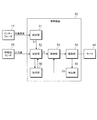
- FIG. 3 is a diagram showing an example of a block diagram of the control device 50.
- the control device 50 includes a CPU, a ROM in which programs executed by the CPU, various data, and the like are stored, a RAM used as a working memory of the CPU, and an EEPROM which is a non-volatile memory. ..
- the operation information of the user interface 17, the output information of the movement amount sensor 75, and the like are input to the control device 50.
- the control device 50 is activated by being supplied with electric power when the motorcycle 1 is activated.
- the control device 50 includes a setting unit 51 that sets a target movement amount Lt of the support member 73 of the jack unit 71, a setting unit 52 that sets a target current It to be supplied to the motor 84, and a drive control that controls the drive of the motor 84. It is provided with a unit 53. Further, the control device 50 includes a drive unit 54 for driving the motor 84 and a detection unit 55 for detecting the motor current Im actually flowing through the motor 84. Further, the control device 50 includes a storage unit 56 that stores the output value and the like of the movement amount sensor 75.
- the setting unit 51, the setting unit 52, and the drive control unit 53 are realized by the CPU executing software stored in a storage area such as a ROM.
- the storage unit 56 is realized by RAM or EEPROM.
- the drive control unit 53 performs feedback control so that the deviation between the target current It set by the setting unit 52 and the motor current Im detected by the detection unit 55 becomes zero.
- the drive unit 54 has, for example, a transistor (FET) as a switching element connected between the positive electrode side line of the power supply and the coil of the motor 84. Then, the drive unit 54 controls the drive of the motor 84 by driving the gate of the transistor and switching the transistor.
- the detection unit 55 detects the motor current Im flowing through the motor 84 from the voltage generated across the shunt resistor connected to the drive unit 54.
- the setting unit 51 sets the target movement amount Lt to a value corresponding to the control mode selected by the user via the user interface 17. For example, on the user interface 17, a control mode corresponding to a target vehicle height in three stages of high, medium, and low is displayed in a selectable manner.
- the target movement amount Lt corresponding to each target vehicle height of high, medium, and low is predetermined and stored.
- the target movement amount Lt corresponding to the highest "high” target vehicle height among high, medium, and low is the highest target value Lth
- Lt may be referred to as a minimum target value Ltl.
- the target movement amount Lt corresponding to the intermediate “medium” target vehicle height among high, medium, and low may be referred to as an intermediate target value Ltm.
- the setting unit 51 sets the target movement amount Lt to the maximum target value Lth. Further, the setting unit 51 sets the target movement amount Lt to the intermediate target value Ltm when the control mode corresponding to the “medium” target vehicle height is selected via the user interface 17. Further, the setting unit 51 sets the target movement amount Lt to the minimum target value Ltl when the control mode corresponding to the “low” target vehicle height is selected via the user interface 17.
- the setting unit 51 sets the target movement amount Lt to 0 in order to move the support member 73 to the reference position where the movement amount of the support member 73 becomes 0 at a predetermined timing. It can be exemplified that the predetermined timing is immediately after the motorcycle 1 is started. Then, after the support member 73 stops at the reference position, the setting unit 51 sets the target movement amount Lt according to the target vehicle height corresponding to the control mode selected via the user interface 17.
- the setting unit 52 moves the target current for moving the piston 82 so that the target movement amount Lt set by the setting unit 51 and the current movement amount La grasped by using the output value of the movement amount sensor 75 match. Set It.
- the setting unit 52 sets the target current It to a predetermined first value for increasing the vehicle height.
- the setting unit 52 sets the target current It to a second value predetermined for lowering the vehicle height.
- a current in the direction of rotating the motor 84 to move the piston 82 to discharge oil from the storage chamber 83 is added, and the motor 84 is rotated to move the piston 82 to discharge oil from the jack chamber 72.
- the first value is 8A and the second value is ⁇ 8A when the current in the direction is negative.
- the predetermined range is, for example, ⁇ 0.2 (mm) or more and 0.2 (mm) or less.
- the setting unit 52 targets to move the piston 82 in the direction of discharging oil from the storage chamber 83.
- the current It is set to the first value.
- the setting unit 52 moves the piston 82 in the direction of discharging the oil from the jack chamber 72.
- the target current It is set to the second value.
- the setting unit 51 when the setting unit 51 is moving the support member 73 due to the setting change of the target movement amount Lt, it may be referred to as “in operation”. Further, during operation, the period from when the subtraction value ⁇ L is within the predetermined range and the setting unit 52 sets the target current It to 0 until the setting unit 51 next changes the setting of the target movement amount Lt is “stopped”. May be called.
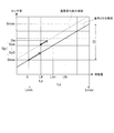
- FIG. 4 is a diagram showing an example of the relationship between the movement amount of the support member 73 and the sensor value which is the output value of the movement amount sensor 75.
- the setting unit 52 calculates the current movement amount La using the following equation (1) during operation.
- La Lp + (Sa-Sp) x Lq / G ... (1)
- Lp, Sa, Sp, Lq, and G have the following values, respectively.
- Lp is the movement amount at the position where the setting unit 51 was stopped when the target movement amount Lt was changed. That is, Lp is the target movement amount Lt during the previous stop.
- Lp is the minimum target value Ltl.
- Sa is the output value of the current movement amount sensor 75.
- Sp is the output value of the movement amount sensor 75 at the position where the setting unit 51 was stopped when the target movement amount Lt was changed.
- Sp is a value stored in the storage unit 56, as will be described later.
- Lq is the amount of movement that the support member 73 can move.
- Lq is the difference between the minimum movement amount Lmin, which is the movement amount when the support member 73 is located at the reference position, and the maximum movement amount Lmax at the position where the support member 73 is moved to the maximum.
- Lq Lmax.
- G is, in other words, the minimum output value Smin which is the output value of the movement amount sensor 75 at the minimum movement amount Lmin and the output value of the movement amount sensor 75 at the maximum movement amount Lmax. It is a difference from a certain maximum output value Smax.
- Lq and G are predetermined and stored in the ROM.
- a reference between the movement amount of the support member 73 and the output value of the movement amount sensor 75 which is a linear relationship connecting the minimum output value Smin at the minimum movement amount Lmin and the maximum output value Smax at the maximum movement amount Lmax.
- the relationship is also stored in the ROM. The reference relationship is determined by using the value measured when the movement amount sensor 75 is at room temperature.
- FIG. 4 also shows an example in which the relationship between the movement amount of the support member 73 and the output value of the movement amount sensor 75 changes due to the change in the temperature around the movement amount sensor 75.
- the output value of the movement amount sensor 75 is large even if the movement amount of the support member 73 is the same due to the change in temperature. Further, in FIG.
- the output value of the movement amount sensor 75 when stopped due to the subtraction value ⁇ L being within a predetermined range is Sp0, and then the setting unit 51 sets the target movement amount Lt.
- the case where the output value of the movement amount sensor 75 when the support member 73 starts to move due to the change is Spn is illustrated.
- the setting unit 52 updates the output value Sp of the movement amount sensor 75 while stopped from Sp0 to Spn.
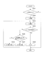
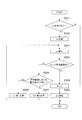
- FIG. 5 is a flowchart showing an example of a procedure for setting the target current It performed by the setting unit 52.
- the setting unit 52 repeatedly executes this process, for example, in a predetermined control cycle (for example, every 1 millisecond).
- the setting unit 52 determines whether or not the target movement amount Lt has been changed by the setting unit 51 (S501).
- the setting unit 52 grasps the changed target movement amount Lt (S502).
- the setting unit 52 calculates the current movement amount La using the above equation (1) (S503).
- the setting unit 52 performs the processing after S503.
- the setting unit 52 sets the target current It to 0 (S508), and ends the process. If the target movement amount Lt has not been changed (No in S501), the setting unit 52 ends the process.
- the setting unit 52 stores the output value of the movement amount sensor 75 while stopped in the storage unit 56. Then, after the setting unit 51 starts moving the support member 73 due to the setting change of the target movement amount Lt, the movement amount from the position of the support member 73 during the stop (previous target movement amount Lt) is changed. , Calculated using the latest output value of the stopped movement amount sensor 75 stored in the storage unit 56. Therefore, even if the output value of the movement amount sensor 75 changes due to the temperature change, the setting unit 52 calculates the current position of the support member 73 with high accuracy by using the changed output value. It will be possible to do.
- the setting unit 52 can set the target current It so that the movement amount of the support member 73 accurately matches the target movement amount Lt even if the temperature changes. Then, the drive control unit 53 performs feedback control so that the deviation between the target current It set by the setting unit 52 and the motor current Im detected by the detection unit 55 becomes zero. As a result, according to the control device 50, the vehicle height can be adjusted to a desired height with high accuracy.
- the setting unit 52 uses the difference between the output value Sa of the movement amount sensor 75 as an example of the sensor at the current position and Sp as an example of the stopped output value stored in the storage unit 56. Then, the current movement amount La is calculated. Therefore, the setting unit 52 and the drive control unit 53 control the movement amount of the support member 73 by using the subtraction value ⁇ L as an example of the deviation between the calculated current movement amount La and the changed target movement amount Lt. , Functions as an example of a control unit.
- the setting unit 51 sets the target movement amount Lt to 0 immediately after the motorcycle 1 is started. Then, when the target movement amount Lt is set to 0 immediately after the motorcycle 1 is started, the setting unit 52 moves the nut 87 to the other side in the rotation axis direction, and the flange 87b of the nut 87 is moved. When it is detected that the screw 86 hits the second part 86b, the target current It is set to 0. The fact that the flange 87b of the nut 87 hits the second portion 86b of the screw 86 is detected, for example, by detecting that the motor current Im detected by the detection portion 55 becomes larger than the reference value. Can be done. However, it may be detected by another method.
- the setting unit 52 sets the target current It to 0 to stop the movement of the support member 73, so that the actual movement of the support member 73 at the stop position is stopped.
- the amount may differ from the target movement amount Lt. If they are different, the setting unit 52 erroneously recognizes the movement amount of the support member 73 as a movement amount different from the actual movement amount even while the vehicle is stopped.
- the setting unit 51 sets the target movement amount Lt to 0, and the setting unit 52 sets the target current It to 0 when the support member 73 is truly positioned at the reference position.
- the setting unit 52 can recognize that the support member 73 is located at the reference position when the support member 73 is truly located at the reference position. As a result, it is possible to suppress setting the target current It while erroneously recognizing the movement amount of the support member 73, so that it becomes easy to adjust the vehicle height with high accuracy. Further, by setting the target movement amount Lt to 0 immediately after the motorcycle 1 is started by the setting unit 51, in addition to the above effect, the driver feels uncomfortable due to the change in vehicle height. It can be made smaller.
- setting the target movement amount Lt to 0 in order to improve the accuracy of vehicle height adjustment is not limited to immediately after the motorcycle 1 is started.
- the setting unit 51 is stopped at the minimum target value Ltl, and when a control mode corresponding to the “medium” or “high” target vehicle height is selected via the user interface 17, the target movement amount Lt. May be set to 0 once before setting the intermediate target value Ltm or the maximum target value Lth. Then, after setting the target movement amount Lt to 0 and detecting that the flange 87b of the nut 87 hits the second portion 86b of the screw 86, for example, the motor current Im detected by the detection portion 55 is used as a reference.
- the target movement amount Lt may be set to the intermediate target value Ltm or the maximum target value Lth.
- the support member is compared with setting the target movement amount Lt to 0 from the state of being stopped at the intermediate target value Ltm or the maximum target value Lth. The amount of movement of 73 can be reduced.
- the temperature change is exemplified as the cause of the change in the output value of the movement amount sensor 75, but the cause of the change in the output value is not limited to the temperature change.
- the above-mentioned function of the control device 50 is also effective when the output value of the movement amount sensor 75 changes due to other changes in the external environment. Further, the configuration of the movement amount sensor 75 is not limited to that having a coil.
- FIG. 6 is a diagram showing an example of a block diagram of the control device 250 provided in the vehicle height adjusting device 200 according to the second embodiment.
- the vehicle height adjusting device 200 according to the second embodiment is different from the vehicle height adjusting device 100 according to the first embodiment in the control device 250 corresponding to the control device 50.
- the control device 250 is different from the control device 50 in that it has a setting unit 252 instead of the setting unit 52.
- the points different from the first embodiment will be described.
- the same reference numerals are used for those having the same function in the first embodiment and the second embodiment, and detailed description thereof will be omitted.
- the setting unit 252 uses the following equation (2) when, for example, it can be determined that the movement amount sensor 75 is at room temperature immediately after the motorcycle 1 is started.
- the current movement amount La is calculated.
- La (Sa-Smin) x Lq / G ... (2)
- Smin is an output value of the movement amount sensor 75 when the support member 73 is located at the reference position (when the minimum movement amount is Lmin).
- Smin is predetermined and stored in ROM.
- the setting unit 252 grasps the elapsed time from the start / stop of the motorcycle 1 to the restart, and when the elapsed time is equal to or longer than a predetermined predetermined time, the movement amount sensor 75 is at room temperature. It can be exemplified that the judgment is made.
- the setting unit 252 has a timer unit for measuring the elapsed time, and by acquiring the elapsed time measured by the timer unit, it can be exemplified that the elapsed time is grasped.
- the setting unit 252 may acquire the elapsed time from a system capable of acquiring time information such as GPS (Global Positioning System) provided in the motorcycle 1 via the vehicle network (for example, CAN).
- GPS Global Positioning System
- the setting unit 252 immediately after the motorcycle 1 is started, the output value Sa of the sensor at the current position is set.
- the current movement amount La is calculated by using the difference between the above and the output value Smin of the sensor at the predetermined reference position.
- FIG. 7 is a diagram showing an example of a block diagram of the control device 350 of the vehicle height adjusting device 300 according to the third embodiment.
- the vehicle height adjusting device 300 according to the third embodiment is different from the vehicle height adjusting device 100 according to the first embodiment in that it has a control device 350 instead of the control device 50.
- the control device 350 differs from the control device 50 in the setting unit 52 and the corresponding setting unit 352.
- the same reference numerals are used for those having the same function in the first embodiment and the third embodiment, and detailed description thereof will be omitted.
- the setting unit 352 sets the target current It to 0 when the subtraction value ⁇ L is within a predetermined range even if the subtraction value ⁇ L is not 0.
- the setting unit 352 calculates the current movement amount La in consideration of the difference between the actual movement amount and the target movement amount Lt at the stop position of the previous support member 73. More specifically, the setting unit 352 calculates the current movement amount La using the following equation (3).
- La Lp + ⁇ Lp + (Sa-Sp) x Lq / G ... (3)
- ⁇ Lp is an error between the actual movement amount and the target movement amount Lt at the stop position of the previous support member 73 when the support member 73 is stopped after the previous operation. In other words, it is the value of the subtraction value ⁇ L when the operation is stopped after the previous operation.
- FIG. 8 is a flowchart showing an example of a procedure for setting the target current It performed by the setting unit 352.
- the setting unit 352 repeatedly executes this process, for example, in a predetermined control cycle (for example, every 1 millisecond).
- the same reference numerals are shown for the same processes as those described with reference to FIG. 5, and detailed description thereof will be omitted.
- the setting unit 352 sets the value of the subtraction value ⁇ L stored in the storage unit 56 to the above equation (Yes). By substituting into ⁇ Lp in 3), the current movement amount La is calculated. As a result, even if an error has occurred at the time of the previous stop, the setting unit 352 calculates the current movement amount La in consideration of the error, so that it is easy to adjust the vehicle height with high accuracy. Similar to the setting unit 252, the setting unit 352 uses the above equation (2) when it can be determined that the movement amount sensor 75 is at room temperature immediately after the motorcycle 1 is started, for example. The movement amount La may be calculated.
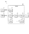
- FIG. 9 is a diagram showing an example of a block diagram of the control device 450 of the vehicle height adjusting device 400 according to the fourth embodiment.
- the vehicle height adjusting device 400 according to the fourth embodiment is different from the vehicle height adjusting device 100 according to the first embodiment in that it has a control device 450 instead of the control device 50.
- the control device 450 is different from the control device 50 in that it has a setting unit 452 corresponding to the setting unit 52 and a filter 456 that smoothes the output value of the movement amount sensor 75.
- the points different from the first embodiment will be described.
- the same reference numerals are used for those having the same function, and detailed description thereof will be omitted.
- the filter 456 performs a filtering process that does not attenuate the component having a frequency lower than the cutoff frequency but attenuates the component having a frequency higher than the cutoff frequency among the output values of the movement amount sensor 75.
- the filter 456 can be exemplified as a low-pass filter.
- the setting unit 452 calculates the current movement amount La using the output value of the movement amount sensor 75 smoothed by the filter 456 and the above equation (1).
- the support member 73 moves to the vehicle body side, for example, when the wheel rides on the convex portion of the road surface.
- the movement amount of the support member 73 fluctuates at high speed according to the input from the wheels, and the output value of the movement amount sensor 75 fluctuates at high speed.
- the change in the output value of the movement amount sensor 75 due to the temperature is not rapid.
- the control device 450 has a filter 456, and the setting unit 452 uses the output value of the movement amount sensor 75 after smoothing by the filter 456 to calculate the current movement amount La. , It becomes easy to consider the change of the output value due to the temperature. As a result, even if the temperature changes, the movement amount of the support member 73 can be easily matched with the target movement amount Lt with high accuracy, and the vehicle height can be adjusted to the target vehicle height with high accuracy.
- control device 450 may have a means for calculating the average value of the output values of the movement amount sensor 75 for a plurality of times instead of providing the filter 456, and the setting unit 452 uses the calculated average value.
- the current movement amount La may be calculated.
- the means for calculating the average value of the output values of the filter 456 or the movement amount sensor 75 described above may be applied to the control device 250 according to the second embodiment and the control device 350 according to the third embodiment. good.
Landscapes
- Engineering & Computer Science (AREA)
- Mechanical Engineering (AREA)
- Vehicle Body Suspensions (AREA)
- Axle Suspensions And Sidecars For Cycles (AREA)
Abstract
制御装置は、車両のサスペンションのスプリングの端部を支持するとともに移動することでスプリングの荷重を変更する支持部材の停止中における、支持部材の移動量に応じた値を出力するセンサの出力値を記憶する記憶部56と、支持部材の目標移動量が変更された後に、現在の位置におけるセンサの出力値と記憶部56に記憶させた停止中の出力値との差を用いて、現在の移動量を算出するとともに、算出した現在の移動量と変更後の目標移動量との偏差を用いて支持部材の移動量を制御する設定部52及び駆動制御部53と、を備える。
Description
本発明は、制御装置、車高調整装置、及び、鞍乗型車両に関する。
近年、車両の姿勢を整える等の目的で、車両の車両本体の高さ(車高)を調整する装置が提案されている。
例えば、特許文献1に記載されたフロントフォーク、リヤサスペンション、制御装置は、自動二輪車の車高を調整する車高調整装置の一例である。この車高調整装置は、スプリングの端部を支持する支持部材が油圧ジャッキに対してスプリングの中心線方向に移動することによりスプリングの初期荷重を変更することで車高を調整する。
例えば、特許文献1に記載されたフロントフォーク、リヤサスペンション、制御装置は、自動二輪車の車高を調整する車高調整装置の一例である。この車高調整装置は、スプリングの端部を支持する支持部材が油圧ジャッキに対してスプリングの中心線方向に移動することによりスプリングの初期荷重を変更することで車高を調整する。
また、近年、コイルのインダクタンス変化に基づきストローク量を検知するセンサが提案されている。
例えば、特許文献2に記載されたセンサは、その上端がピストンに取付けられ、下端側に延設された導体部材と、その下端がインナチューブの下端に取付けられ、上端側に延設され、導体部材が挿入可能なコイル導体とを備える。そして、センサは、コイル導体のインダクタンス変化に基づき、ストローク量を検知する。
例えば、特許文献2に記載されたセンサは、その上端がピストンに取付けられ、下端側に延設された導体部材と、その下端がインナチューブの下端に取付けられ、上端側に延設され、導体部材が挿入可能なコイル導体とを備える。そして、センサは、コイル導体のインダクタンス変化に基づき、ストローク量を検知する。
車高調整装置の支持部材の移動量を検出するセンサを備え、このセンサの出力値を用いて車高を調整することが考えられる。そして、このセンサとして、特許文献2に記載されたセンサのように、コイルを備え、コイルに生じるインダクタンスの変化に基づいて、支持部材の移動量を検知するセンサを採用することが考えられる。しかしながら、コイルを有するセンサは温度変化によってセンサの出力値が大きく変わる場合があるため、車高を精度高く調整することができないおそれがある。
本発明は、温度変化が生じたとしても車高を精度高く調整することができる制御装置等を提供することを目的とする。
本発明は、温度変化が生じたとしても車高を精度高く調整することができる制御装置等を提供することを目的とする。
以下、本開示について説明する。
本開示の1つの態様は、車両のサスペンションのスプリングの端部を支持するとともに移動することで前記スプリングの荷重を変更する支持部材の停止中における、前記支持部材の移動量に応じた値を出力するセンサの出力値を記憶する記憶部と、前記支持部材の目標移動量が変更された後に、現在の位置における前記センサの出力値と前記記憶部に記憶させた前記停止中の前記出力値との差を用いて、現在の移動量を算出するとともに、算出した前記現在の移動量と変更後の前記目標移動量との偏差を用いて前記支持部材の移動量を制御する制御部と、を備える制御装置である。
ここで、前記制御部は、前記偏差が所定範囲内である場合に前記支持部材を停止させても良い。
また、前記制御部は、前記支持部材を停止させたときの、停止位置における移動量と前記目標移動量との差である誤差を記憶し、その後、前記支持部材の前記目標移動量が変更されたことに起因して前記現在の移動量を算出する際には、前記誤差を用いて算出しても良い。
また、前記制御部は、予め定められたタイミングで、前記支持部材を、前記支持部材の移動量が0となる基準位置まで移動させても良い。
また、前記予め定められたタイミングは、前記車両が起動された直後であっても良い。
また、前記制御部は、前記車両が起動停止された後に再度起動されるまでの経過時間が予め定められた所定時間以上である場合に、前記車両が起動された直後に、現在の位置におけるセンサの出力値と予め定められた基準位置におけるセンサの出力値との差を用いて、現在の移動量を算出しても良い。
本開示の他の態様は、車両のサスペンションのスプリングの端部を支持するとともに移動することで前記スプリングの荷重を変更する支持部材を有し、前記支持部材の移動量を変更することで前記車両の高さを調整可能な調整部と、前記支持部材の移動量を制御する上記した態様に係る制御装置と、を備える車高調整装置である。
本開示の他の態様は、車両本体と、車輪と、上記した態様に係る車高調整装置と、を備える鞍乗型車両である。
本発明によれば、温度変化が生じたとしても車高を精度高く調整することができる制御装置等を提供することができる。
以下、添付図面を参照して、本発明の実施の形態について詳細に説明する。なお、以下に示す形態は本発明の実施の形態の一例であり、本発明は、以下に示す形態に限定されない。
<第1の実施形態>
図1は、第1の実施形態に係る自動二輪車1の概略構成の一例を示す図である。
図2は、車高調整装置100の概略構成の一例を示す図である。
鞍乗型車両の一例としての自動二輪車1は、前側の車輪である前輪2と、後側の車輪である後輪3と、車両本体10とを備えている。車両本体10は、自動二輪車1の骨格をなす車体フレーム11と、ハンドル12と、ブレーキレバー13と、シート14と、ユーザが操作可能なユーザインターフェース17とを有する。
図1は、第1の実施形態に係る自動二輪車1の概略構成の一例を示す図である。
図2は、車高調整装置100の概略構成の一例を示す図である。
鞍乗型車両の一例としての自動二輪車1は、前側の車輪である前輪2と、後側の車輪である後輪3と、車両本体10とを備えている。車両本体10は、自動二輪車1の骨格をなす車体フレーム11と、ハンドル12と、ブレーキレバー13と、シート14と、ユーザが操作可能なユーザインターフェース17とを有する。
また、自動二輪車1は、前輪2と車両本体10とを連結する前輪2側のサスペンション21を、前輪2の左側と右側にそれぞれ1つずつ有している。また、自動二輪車1は、2つのサスペンション21を保持する2つのブラケット15と、2つのブラケット15の間に配置されたシャフト16とを備えている。サスペンション21は、路面等から前輪2に加わった衝撃を吸収するスプリング21sと、スプリング21sの振動を減衰する減衰装置21dとを備えている。
また、自動二輪車1は、後輪3と車両本体10とを連結する後輪3側のサスペンション22を、後輪3の左側と右側にそれぞれ1つずつ有している。サスペンション22は、路面等から後輪3に加わった衝撃を吸収するスプリング22sと、スプリング22sの振動を減衰する減衰装置22dとを備えている。
以下の説明において、前輪2と後輪3とをまとめて「車輪」、車両本体10を「車体」と称する場合もある。また、前輪2側のサスペンション21と後輪3側のサスペンション22とをまとめて「サスペンション23」と称する場合もある。また、スプリング21sとスプリング22sとをまとめて「スプリング23s」と称する場合もある。
以下の説明において、前輪2と後輪3とをまとめて「車輪」、車両本体10を「車体」と称する場合もある。また、前輪2側のサスペンション21と後輪3側のサスペンション22とをまとめて「サスペンション23」と称する場合もある。また、スプリング21sとスプリング22sとをまとめて「スプリング23s」と称する場合もある。
また、自動二輪車1は、スプリング23sに付与する初期荷重(プリロード)を変更することにより、車両本体10の高さ、言い換えれば、車高を調整する調整部70を備えている。
また、自動二輪車1は、スプリング23sの初期荷重を制御する制御装置50を備えている。
また、自動二輪車1は、スプリング23sの初期荷重を制御する制御装置50を備えている。
(調整部70)
図1及び図2を参照する。調整部70は、サスペンション23に設けられて、スプリング23sの長さを調整するジャッキ部71と、ジャッキ部71のジャッキ室72にオイルを供給する供給装置80と、を備えている。
ジャッキ部71は、スプリング23sの車両本体10側の端部を支持する支持部材73と、支持部材73とともにジャッキ室72を形成する形成部材74とを有し、ジャッキ室72内のオイルの量に応じて支持部材73が移動することで、スプリング23sの長さを調整する。支持部材73、ジャッキ室72、及び、形成部材74は、それぞれ、特許文献1に記載されたリヤサスペンション又はフロントフォークの支持部材、ジャッキ室、及び、油圧ジャッキにて実現されることを例示することができる。
また、ジャッキ部71は、支持部材73の移動量を検出する移動量センサ75を備えている。移動量センサ75が検出する支持部材73の移動量は、支持部材73が基準位置に位置するときの移動量を0とした場合の移動量である。基準位置は、例えば、ジャッキ室72内のオイルが0のときの支持部材73の位置である。移動量センサ75は、例えば、形成部材74の外周面に不図示のコイルを巻くとともに、支持部材73を磁性体とし、形成部材74に対する支持部材73の移動に応じて変化するコイルのインダクタンスを用いて支持部材73の移動量を検出するセンサである。移動量センサ75は、コイルのインダクタンスに関する情報を検知するとともにインダクタンスの変化に応じた周期(周波数)で発振を行う不図示の発振回路と、発振回路による発振波形の周波数に応じた値を計測して、出力する不図示のタイマー部と、を有している。以下では、タイマー部から出力された値を、「移動量センサ75の出力値」、又は、「出力値」と称する場合がある。なお、発振回路及びタイマー部は、制御装置50に設けても良いし、制御装置50とは別の部材に設けても良い。
供給装置80は、図2に示すように、オイルを貯留するハウジング81と、ハウジング81内を摺動する円柱状のピストン82と、を備えている。ハウジング81の内面、及び、ピストン82にて囲まれる空間に、オイルを貯留する貯留室83が形成される。
また、供給装置80は、モータ84と、モータ84の回転速度を減速させる減速機85と、減速機85の出力軸85aに連結されたスクリュー86とを備えている。
モータ84は、ブラシ付きの直流(DC)モータであることを例示することができる。モータ84の駆動は、制御装置50によって制御される。減速機85は、周知の遊星歯車機構を用いた遊星減速機であることを例示することができる。
スクリュー86は、それぞれ径が異なる3つの円柱状の部位である、第1部86a、第2部86b、及び、第3部86cを、回転軸方向の一方側(図2では右側)から他方側(図2では左側)にかけて順に有する。第2部86bの外径は、第1部86aの外径及び第3部86cの外径よりも大きい。第1部86aの外周面に、雄ねじ86dが形成されている。第3部86cの内側には、減速機85の出力軸85aが嵌め込まれている。これにより、スクリュー86は、減速機85の出力軸85aと一体的に回転する。
また、供給装置80は、スクリュー86の第1部86aに形成された雄ねじ86dと噛み合う雌ねじ87aが形成されたナット87を有している。ナット87は、他方側の端部にフランジ87bを有している。
また、供給装置80は、ナット87のフランジ87bと、ピストン82との間に介在する介在部材88と、介在部材88の内側であってナット87の外側に配置された円筒状のカラー89と、介在部材88の外側に配置された円筒状のカラー90とを有している。介在部材88は、弾性部材であり、オイルから力を受けたピストン82により加圧されることにより弾性変形した状態で、ピストン82とナット87のフランジ87bとの間に挟み込まれている。これにより、介在部材88は、スクリュー86の回転に従って、ナット87が回転することを抑制する。
また、供給装置80は、ナット87のフランジ87bと、ピストン82との間に介在する介在部材88と、介在部材88の内側であってナット87の外側に配置された円筒状のカラー89と、介在部材88の外側に配置された円筒状のカラー90とを有している。介在部材88は、弾性部材であり、オイルから力を受けたピストン82により加圧されることにより弾性変形した状態で、ピストン82とナット87のフランジ87bとの間に挟み込まれている。これにより、介在部材88は、スクリュー86の回転に従って、ナット87が回転することを抑制する。
また、供給装置80は、スクリュー86を回転可能に支持するベアリング91と、ベアリング91を支持する支持部材92とを有している。ベアリング91は、支持部材92と、スクリュー86の第2部86bとの間に配置されている。
上述した、ピストン82、モータ84、減速機85、スクリュー86、ナット87、介在部材88、カラー89、カラー90、ベアリング91、及び、支持部材92は、ハウジング81内に収容されている。
そして、供給装置80は、ハウジング81に装着されるとともに、貯留室83と、ジャッキ部71のジャッキ室72との間に設けられて、貯留室83とジャッキ室72との間でオイルを流通させるホース93を備えている。
上述した、ピストン82、モータ84、減速機85、スクリュー86、ナット87、介在部材88、カラー89、カラー90、ベアリング91、及び、支持部材92は、ハウジング81内に収容されている。
そして、供給装置80は、ハウジング81に装着されるとともに、貯留室83と、ジャッキ部71のジャッキ室72との間に設けられて、貯留室83とジャッキ室72との間でオイルを流通させるホース93を備えている。
以上のように構成された調整部70においては、供給装置80のモータ84の軸が回転することにより、これと同じ方向にスクリュー86が回転し、ナット87が回転軸方向の一方側に移動する。ナット87の移動に伴い、カラー89、カラー90及び介在部材88が、回転軸方向の他方側から一方側に向かう力を受け、ピストン82を回転軸方向の一方側に移動させる。これにより、貯留室83からオイルが排出され、ホース93を介して、ジャッキ室72内にオイルが供給される。その結果、支持部材73が形成部材74に対して車輪側(図2では右側)に移動し、言い換えれば、支持部材73の基準位置からの移動量が大きくなり、スプリング23sのバネ長が短くなる。
スプリング23sのバネ長が短くなると、支持部材73が形成部材74に対して移動する前と比べてスプリング23sが支持部材73を押す力が大きくなる。その結果、車体から車輪側へ力が作用したとしても、両者の相対位置を変化させない初期荷重が大きくなる。かかる場合、車体側から車輪側に同じ力が作用した場合には、サスペンション23の沈み込み量(車体と車輪との間の距離の変化)が小さくなる。それゆえ、支持部材73が形成部材74に対して移動することでスプリング23sのバネ長が短くなると、支持部材73が形成部材74に対して移動する前と比べて、車両本体10の高さが上昇する(車高が高くなる)。
一方、供給装置80のモータ84の軸が上記と逆の方向に回転することにより、スクリュー86も、上記と逆の方向に回転する。すると、カラー89、カラー90及び介在部材88を介して、貯留室83のオイルの力を受けるピストン82からの力がナット87のフランジ87bに作用し、ナット87が回転軸方向の他方側に移動する。ナット87の他方側への移動に伴い、貯留室83の容積が大きくなる。これにより、支持部材73がジャッキ室72内のオイルを排出し、これを貯留室83に供給する。その結果、支持部材73が形成部材74に対して車体側(図2では左側)に移動し、言い換えれば、支持部材73の基準位置からの移動量が小さくなり、スプリング23sのバネ長が長くなる。
スプリング23sのバネ長が長くなると、支持部材73が形成部材74に対して移動する前と比べてスプリング23sが支持部材73を押す力が小さくなる。その結果、車体側から車輪側に同じ力が作用した場合には、サスペンション23の沈み込み量が大きくなる。それゆえ、支持部材73が形成部材74に対して移動することでスプリング23sのバネ長が長くなると、支持部材73が形成部材74に対して移動する前と比べて、車両本体10の高さが下降する(車高が低くなる)。
以上のように構成された調整部70、及び、制御装置50等により、自動二輪車1の車高を調整する車高調整装置100が構成される。
(制御装置50)
次に、制御装置50について説明する。
図3は、制御装置50のブロック図の一例を示す図である。
制御装置50は、CPUと、CPUにて実行されるプログラムや各種データ等が記憶されたROMと、CPUの作業用メモリ等として用いられるRAMと、不揮発性メモリであるEEPROMと、を備えている。制御装置50には、ユーザインターフェース17の操作情報、移動量センサ75の出力情報等が入力される。制御装置50は、自動二輪車1が起動されることで電力が供給されて起動する。
次に、制御装置50について説明する。
図3は、制御装置50のブロック図の一例を示す図である。
制御装置50は、CPUと、CPUにて実行されるプログラムや各種データ等が記憶されたROMと、CPUの作業用メモリ等として用いられるRAMと、不揮発性メモリであるEEPROMと、を備えている。制御装置50には、ユーザインターフェース17の操作情報、移動量センサ75の出力情報等が入力される。制御装置50は、自動二輪車1が起動されることで電力が供給されて起動する。
制御装置50は、ジャッキ部71の支持部材73の目標移動量Ltを設定する設定部51と、モータ84に供給する目標電流Itを設定する設定部52と、モータ84の駆動を制御する駆動制御部53と、を備えている。また、制御装置50は、モータ84を駆動させる駆動部54と、モータ84に実際に流れるモータ電流Imを検出する検出部55と、を備えている。また、制御装置50は、移動量センサ75の出力値等を記憶する記憶部56を備えている。設定部51、設定部52、及び、駆動制御部53は、CPUがROM等の記憶領域に記憶されたソフトウェアを実行することにより実現される。記憶部56は、RAM又はEEPROMにて実現される。
駆動制御部53は、設定部52にて設定された目標電流Itと、検出部55にて検出されたモータ電流Imとの偏差が0となるようにフィードバック制御を行う。
駆動部54は、例えば、電源の正極側ラインとモータ84のコイルとの間に接続された、スイッチング素子としてのトランジスタ(FET)を有している。そして、駆動部54は、このトランジスタのゲートを駆動してこのトランジスタをスイッチング動作させることにより、モータ84の駆動を制御する。
検出部55は、駆動部54に接続されたシャント抵抗の両端に生じる電圧から、モータ84に流れるモータ電流Imを検出する。
駆動部54は、例えば、電源の正極側ラインとモータ84のコイルとの間に接続された、スイッチング素子としてのトランジスタ(FET)を有している。そして、駆動部54は、このトランジスタのゲートを駆動してこのトランジスタをスイッチング動作させることにより、モータ84の駆動を制御する。
検出部55は、駆動部54に接続されたシャント抵抗の両端に生じる電圧から、モータ84に流れるモータ電流Imを検出する。
設定部51は、ユーザインターフェース17を介してユーザにより選択された制御形態に応じた値に、目標移動量Ltを設定する。例えば、ユーザインターフェース17に、高・中・低の3段階の目標車高と対応する制御形態が、選択可能に表示される。ROMには、高・中・低、それぞれの目標車高に応じた目標移動量Ltが予め定められ、記憶されている。以下では、高・中・低の内、一番高い「高」の目標車高に対応する目標移動量Ltを最高目標値Lth、一番低い「低」の目標車高に対応する目標移動量Ltを最低目標値Ltlと称する場合がある。また、高・中・低の内、中間の「中」の目標車高に対応する目標移動量Ltを中間目標値Ltmと称する場合がある。
設定部51は、ユーザインターフェース17を介して「高」の目標車高と対応する制御形態が選択された場合には、目標移動量Ltを最高目標値Lthに設定する。また、設定部51は、ユーザインターフェース17を介して「中」の目標車高と対応する制御形態が選択された場合には、目標移動量Ltを中間目標値Ltmに設定する。また、設定部51は、ユーザインターフェース17を介して「低」の目標車高と対応する制御形態が選択された場合には、目標移動量Ltを最低目標値Ltlに設定する。
また、設定部51は、予め定められたタイミングで、支持部材73の移動量が0となる基準位置まで移動させるべく、目標移動量Ltを0に設定する。予め定められたタイミングは、自動二輪車1が起動された直後であることを例示することができる。そして、設定部51は、支持部材73が基準位置で停止した後に、ユーザインターフェース17を介して選択された制御形態と対応する目標車高に応じた目標移動量Ltに設定する。
設定部52は、設定部51が設定した目標移動量Ltと、移動量センサ75の出力値を用いて把握した現在の移動量Laとが一致するように、ピストン82を移動させるための目標電流Itを設定する。
設定部52は、貯留室83からオイルを排出させる方向にピストン82を移動させる場合には、目標電流Itを、車高を上昇させるために予め定められた第1の値に設定する。他方、設定部52は、ジャッキ室72からオイルを排出させる方向にピストン82を移動させる場合には、目標電流Itを、車高を下降させるために予め定められた第2の値に設定する。なお、貯留室83からオイルを排出させるべくピストン82を移動させるようにモータ84を回転させる方向の電流をプラス、ジャッキ室72からオイルを排出させるべくピストン82を移動させるようにモータ84を回転させる方向の電流をマイナスとした場合に、第1の値は8A、第2の値は-8Aであることを例示することができる。
設定部52は、貯留室83からオイルを排出させる方向にピストン82を移動させる場合には、目標電流Itを、車高を上昇させるために予め定められた第1の値に設定する。他方、設定部52は、ジャッキ室72からオイルを排出させる方向にピストン82を移動させる場合には、目標電流Itを、車高を下降させるために予め定められた第2の値に設定する。なお、貯留室83からオイルを排出させるべくピストン82を移動させるようにモータ84を回転させる方向の電流をプラス、ジャッキ室72からオイルを排出させるべくピストン82を移動させるようにモータ84を回転させる方向の電流をマイナスとした場合に、第1の値は8A、第2の値は-8Aであることを例示することができる。
設定部52は、ピストン82の移動方向を決定するにあたって、先ず、目標移動量Ltから、後述するようにして算出した現在の移動量Laを減算した減算値ΔL(=Lt-La)が、予め定められた所定範囲内であるか否かを判断する。そして、減算値ΔLが所定範囲内である場合、設定部52は、目標電流Itを0に設定する。なお、所定範囲は、例えば、-0.2(mm)以上、0.2(mm)以下であることを例示することができる。また、設定部52は、減算値ΔLが所定範囲における最大値より大きい場合(例えばΔL>0.2(mm))、ピストン82を、貯留室83からオイルを排出させる方向に移動させるべく、目標電流Itを第1の値に設定する。他方、減算値ΔLが所定範囲における最小値より小さい場合(例えばΔL<-0.2(mm))、設定部52は、ピストン82を、ジャッキ室72からオイルを排出させる方向に移動させるべく、目標電流Itを第2の値に設定する。
以下では、設定部51が目標移動量Ltを設定変更したことに起因して支持部材73を移動させているときを「動作中」と称する場合がある。また、動作中のときに減算値ΔLが所定範囲内となり設定部52が目標電流Itを0にしてから、設定部51が次に目標移動量Ltを設定変更するまでの間を「停止中」と称する場合がある。
図4は、支持部材73の移動量と移動量センサ75の出力値であるセンサ値との関係の一例を示す図である。
設定部52は、動作中に、以下の式(1)を用いて現在の移動量Laを算出する。
La=Lp+(Sa-Sp)×Lq/G・・・(1)
ここで、Lp、Sa、Sp、Lq、Gは、それぞれ、以下の値であることを例示することができる。
Lpは、設定部51が目標移動量Ltを変更したときに停止していた位置における移動量である。つまり、Lpは、前回の停止中における目標移動量Ltである。例えば、「低」の目標車高が選択されて支持部材73の移動量が最低目標値Ltlであるときに、ユーザインターフェース17を介して、目標車高が「中」に変更された場合には、Lpは、最低目標値Ltlである。
Saは、現在の移動量センサ75の出力値である。
Spは、設定部51が目標移動量Ltを変更したときに停止していた位置における移動量センサ75の出力値である。Spは、後述するように、記憶部56に記憶された値である。
Lqは、支持部材73が移動可能な移動量である。言い換えれば、Lqは、支持部材73が基準位置に位置するときの移動量である最小移動量Lminと、支持部材73が最大限に移動した位置における最大移動量Lmaxとの差である。なお、本実施形態においては、最小移動量Lminは0であることから、Lq=Lmaxである。
Gは、支持部材73が基準位置に位置するとき、言い換えれば、最小移動量Lminにおける移動量センサ75の出力値である最小出力値Sminと、最大移動量Lmaxにおける移動量センサ75の出力値である最大出力値Smaxとの差である。
Lq及びGは、予め定められ、ROMに記憶されている。また、最小移動量Lminにおける最小出力値Sminと、最大移動量Lmaxにおける最大出力値Smaxとを結んだ直線的な関係である、支持部材73の移動量と移動量センサ75の出力値との基準となる関係もROMに記憶されている。なお、基準となる関係は、移動量センサ75が常温であるときに計測された値を用いて定められている。
また、設定部52は、停止中に、定期的に、移動量センサ75の出力値を取得するとともに、取得した出力値を記憶部56に記憶させる。このようにして記憶部56に記憶された出力値が、上記Spである。図4には、移動量センサ75の周辺の温度が変化したことにより、支持部材73の移動量と移動量センサ75の出力値との関係が変化した例をも示している。図4に示した例は、温度が変化したことにより、支持部材73の移動量が同じであったとしても、移動量センサ75の出力値が大きくなっている。また、図4には、減算値ΔLが所定範囲内となったことに起因して停止したときの移動量センサ75の出力値がSp0であり、その後、設定部51が目標移動量Ltを設定変更したことに起因して支持部材73を移動開始したときの移動量センサ75の出力値がSpnであった場合を例示している。図4に示した例の場合には、設定部52は、停止中における移動量センサ75の出力値Spを、Sp0からSpnまで更新する。
図5は、設定部52が行う目標電流Itの設定処理の手順の一例を示すフローチャートである。
設定部52は、この処理を、例えば予め定めた制御周期にて(例えば1ミリ秒毎に)繰り返し実行する。
設定部52は、先ず、設定部51により目標移動量Ltが変更されたか否かを判断する(S501)。目標移動量Ltが変更された場合(S501でYes)、設定部52は、変更後の目標移動量Ltを把握する(S502)。その後、設定部52は、上記式(1)を用いて現在の移動量Laを算出する(S503)。その後、設定部52は、S502にて把握した目標移動量LtからS503にて算出した現在の移動量Laを減算した減算値ΔL(=Lt-La)が所定範囲内であるか否かを判断する(S504)。減算値ΔLが所定範囲内ではない場合(S504でNo)、設定部52は、減算値ΔLが所定範囲における最大値より大きいか否かを判断する(S505)。そして、減算値ΔLが最大値より大きい場合(S505でYes)、設定部52は、貯留室83からオイルを排出させる方向にピストン82を移動させるべく、目標電流Itを上記第1の値に設定する(S506)。その後、設定部52は、S503以降の処理を行う。
他方、減算値ΔLが最大値より大きくない場合(S505でNo)、減算値ΔLが所定範囲における最小値より小さいと考えられるので、設定部52は、ジャッキ室72からオイルを排出させる方向にピストン82を移動させるべく、目標電流Itを上記第2の値に設定する(S507)。その後、設定部52は、S503以降の処理を行う。
一方、減算値ΔLが所定範囲内である場合(S504でYes)、設定部52は、目標電流Itを0に設定し(S508)、処理を終了する。
また、目標移動量Ltが変更されていない場合(S501でNo)、設定部52は、処理を終了する。
一方、減算値ΔLが所定範囲内である場合(S504でYes)、設定部52は、目標電流Itを0に設定し(S508)、処理を終了する。
また、目標移動量Ltが変更されていない場合(S501でNo)、設定部52は、処理を終了する。
以上のように構成された自動二輪車1においては、設定部52は、停止中における移動量センサ75の出力値を記憶部56に記憶する。そして、設定部51が目標移動量Ltを設定変更したことに起因して支持部材73を移動開始した後には、停止中における支持部材73の位置(前回の目標移動量Lt)からの移動量を、記憶部56に記憶した、停止中の移動量センサ75の最新の出力値を用いて算出する。それゆえ、設定部52は、温度変化により、たとえ、停止中に、移動量センサ75の出力値が変化したとしても、変化後の出力値を用いて、支持部材73の現在位置を精度高く算出することが可能になる。その結果、設定部52は、温度変化が生じたとしても、支持部材73の移動量が目標移動量Ltに精度高く合うように、目標電流Itを設定することが可能となる。そして、駆動制御部53が、設定部52にて設定された目標電流Itと、検出部55にて検出されたモータ電流Imとの偏差が0となるようにフィードバック制御を行う。その結果、制御装置50によれば、車高を所望の高さに精度高く調整することができる。
上述したように、設定部52は、現在の位置におけるセンサの一例としての移動量センサ75の出力値Saと記憶部56に記憶させた停止中の出力値の一例としてのSpとの差を用いて、現在の移動量Laを算出する。それゆえ、設定部52及び駆動制御部53は、算出した現在の移動量Laと変更後の目標移動量Ltとの偏差の一例としての減算値ΔLを用いて支持部材73の移動量を制御する、制御部の一例として機能する。
また、設定部51は、自動二輪車1が起動された直後には、目標移動量Ltを0に設定する。そして、設定部52は、自動二輪車1が起動された直後に目標移動量Ltが0に設定された場合には、ナット87が回転軸方向の他方側に移動して、ナット87のフランジ87bがスクリュー86の第2部86bに突き当たったことを検知した場合に目標電流Itを0に設定する。ナット87のフランジ87bがスクリュー86の第2部86bに突き当たったことは、例えば、検出部55にて検出されたモータ電流Imが基準値よりも大きくなったことを検知することで、検知することができる。ただし、その他の手法で検知しても良い。
動作中に、減算値ΔLが所定範囲内となったときに設定部52が目標電流Itを0に設定することで支持部材73の移動が停止するため、支持部材73の停止位置における実際の移動量が目標移動量Ltと異なる場合がある。そして、異なる場合には、設定部52は、停止中においても、支持部材73の移動量を、実際の移動量とは異なる移動量に誤認識してしまう。本実施形態おいては、設定部51が目標移動量Ltを0に設定し、支持部材73が真に基準位置に位置したときに設定部52が目標電流Itを0に設定する。これにより、設定部52は、支持部材73が真に基準位置に位置しているときに、支持部材73が基準位置に位置していると認識することができる。その結果、支持部材73の移動量を誤認識したまま目標電流Itを設定することを抑制できるので、車高を精度高く調整しやすくなる。また、設定部51が、自動二輪車1が起動された直後に目標移動量Ltを0に設定することにより、上記効果に加えて、車高が変化することに起因して運転者に与える違和感を小さくすることが可能となる。
なお、車高調整の精度を高めるために目標移動量Ltを0に設定するのは、自動二輪車1が起動された直後に限定されない。例えば、設定部51は、最低目標値Ltlで停止中に、ユーザインターフェース17を介して、「中」又は「高」の目標車高と対応する制御形態が選択された場合に、目標移動量Ltを中間目標値Ltm又は最高目標値Lthに設定する前に、一旦、目標移動量Ltを0に設定しても良い。そして、目標移動量Ltを0に設定して、ナット87のフランジ87bがスクリュー86の第2部86bに突き当たったことを検知した後、例えば、検出部55にて検出されたモータ電流Imが基準値よりも大きくなった後に、目標移動量Ltを中間目標値Ltm又は最高目標値Lthに設定すると良い。この態様である場合には、誤認識を解消するために、例えば、中間目標値Ltm又は最高目標値Lthで停止中の状態から目標移動量Ltを0に設定するのと比較して、支持部材73の移動量を少なくすることができる。
また、上記説明では、移動量センサ75の出力値が変わってしまう原因として温度変化を例示しているが、出力値が変わる原因は温度変化に限定されない。上述した制御装置50の機能は、その他の外部環境の変化で移動量センサ75の出力値が変化する場合にも、有効である。また、移動量センサ75の構成は、コイルを有するものに限定されない。
<第2の実施形態>
図6は、第2の実施形態に係る車高調整装置200に備えられる制御装置250の、ブロック図の一例を示す図である。
第2の実施形態に係る車高調整装置200は、第1の実施形態に係る車高調整装置100に対して、制御装置50に相当する制御装置250が異なる。制御装置250は、制御装置50に対して、設定部52に代えて設定部252を有する点が異なる。以下、第1の実施形態と異なる点について説明する。第1の実施形態と第2の実施形態とで、同じ機能を有するものについては同じ符号を用い、その詳細な説明は省略する。
図6は、第2の実施形態に係る車高調整装置200に備えられる制御装置250の、ブロック図の一例を示す図である。
第2の実施形態に係る車高調整装置200は、第1の実施形態に係る車高調整装置100に対して、制御装置50に相当する制御装置250が異なる。制御装置250は、制御装置50に対して、設定部52に代えて設定部252を有する点が異なる。以下、第1の実施形態と異なる点について説明する。第1の実施形態と第2の実施形態とで、同じ機能を有するものについては同じ符号を用い、その詳細な説明は省略する。
設定部252は、設定部52が有する機能に加えて、例えば、自動二輪車1が起動された直後に、移動量センサ75が常温であると判断できる場合は、以下の式(2)を用いて現在の移動量Laを算出する。
La=(Sa-Smin)×Lq/G・・・(2)
ここで、Sminは、支持部材73が基準位置に位置するとき(最小移動量Lminであるとき)の移動量センサ75の出力値である。Sminは、予め定められ、ROMに記憶されている。
La=(Sa-Smin)×Lq/G・・・(2)
ここで、Sminは、支持部材73が基準位置に位置するとき(最小移動量Lminであるとき)の移動量センサ75の出力値である。Sminは、予め定められ、ROMに記憶されている。
設定部252は、自動二輪車1が起動停止された後、再度起動されるまでの経過時間を把握し、経過時間が予め定められた所定時間以上である場合に、移動量センサ75が常温であると判断することを例示することができる。設定部252は、経過時間を計測するタイマー部を有し、このタイマー部が計測した経過時間を取得することで、経過時間を把握することを例示することができる。あるいは、設定部252は、自動二輪車1に設けられたGPS(Global Positioning System)等の時間情報を取得可能なシステムから、車両ネットワーク(例えばCAN)を介して、経過時間を取得しても良い。
このように、設定部252は、自動二輪車1が起動停止された後に再度起動されるまでの経過時間が所定時間以上である場合に、起動された直後に、現在の位置におけるセンサの出力値Saと予め定められた基準位置におけるセンサの出力値Sminとの差を用いて、現在の移動量Laを算出する。これにより、設定部252が支持部材73の移動量を誤認識したまま目標電流Itを設定することを抑制できるので、車高を精度高く調整することができる。
<第3の実施形態>
図7は、第3の実施形態に係る車高調整装置300の制御装置350のブロック図の一例を示す図である。
第3の実施形態に係る車高調整装置300は、第1の実施形態に係る車高調整装置100に対して、制御装置50に代えて制御装置350を有する点が異なる。制御装置350は、制御装置50に対して、設定部52と対応する設定部352が異なる。以下、第1の実施形態と異なる点について説明する。第1の実施形態と第3の実施形態とで、同じ機能を有するものについては同じ符号を用い、その詳細な説明は省略する。
図7は、第3の実施形態に係る車高調整装置300の制御装置350のブロック図の一例を示す図である。
第3の実施形態に係る車高調整装置300は、第1の実施形態に係る車高調整装置100に対して、制御装置50に代えて制御装置350を有する点が異なる。制御装置350は、制御装置50に対して、設定部52と対応する設定部352が異なる。以下、第1の実施形態と異なる点について説明する。第1の実施形態と第3の実施形態とで、同じ機能を有するものについては同じ符号を用い、その詳細な説明は省略する。
設定部352は、設定部52と同様に、減算値ΔLが0でなくても、減算値ΔLが所定範囲内となったときに目標電流Itを0に設定する。加えて、設定部352は、前回の支持部材73の停止位置における実際の移動量と目標移動量Ltとの差を考慮して、現在の移動量Laを算出する。より具体的には、設定部352は、以下の式(3)を用いて現在の移動量Laを算出する。
La=Lp+ΔLp+(Sa-Sp)×Lq/G・・・(3)
ここで、ΔLpは、前回動作後に停止させたときの、前回の支持部材73の停止位置における実際の移動量と目標移動量Ltとの誤差である。言い換えれば、前回動作後に停止させたときの減算値ΔLの値である。
La=Lp+ΔLp+(Sa-Sp)×Lq/G・・・(3)
ここで、ΔLpは、前回動作後に停止させたときの、前回の支持部材73の停止位置における実際の移動量と目標移動量Ltとの誤差である。言い換えれば、前回動作後に停止させたときの減算値ΔLの値である。
図8は、設定部352が行う目標電流Itの設定処理の手順の一例を示すフローチャートである。
設定部352は、この処理を、例えば予め定めた制御周期にて(例えば1ミリ秒毎に)繰り返し実行する。
図5を用いて説明した設定処理と同じ処理については同じ符号を示し、その詳細な説明は省略する。設定部352は、上記式(3)を用いて現在の移動量Laを算出し(S503)、S502にて把握した目標移動量LtからS503にて算出した現在の移動量Laを減算した減算値ΔL(=Lt-La)が所定範囲内であるか否かを判断する(S504)。そして、減算値ΔLが所定範囲内である場合、設定部352は、目標電流Itを0に設定し(S508)、S504にて算出した減算値ΔLを記憶部56に記憶する(S809)。
設定部352は、この処理を、例えば予め定めた制御周期にて(例えば1ミリ秒毎に)繰り返し実行する。
図5を用いて説明した設定処理と同じ処理については同じ符号を示し、その詳細な説明は省略する。設定部352は、上記式(3)を用いて現在の移動量Laを算出し(S503)、S502にて把握した目標移動量LtからS503にて算出した現在の移動量Laを減算した減算値ΔL(=Lt-La)が所定範囲内であるか否かを判断する(S504)。そして、減算値ΔLが所定範囲内である場合、設定部352は、目標電流Itを0に設定し(S508)、S504にて算出した減算値ΔLを記憶部56に記憶する(S809)。
そして、次回以降の設定処理において、目標移動量Ltが変更された場合(S501でYes)のS503の処理で、設定部352は、記憶部56に記憶された減算値ΔLの値を上記式(3)のΔLpに代入して、現在の移動量Laを算出する。これにより、設定部352は、前回の停止時に誤差が生じていたとしても、その誤差を考慮して現在の移動量Laを算出するので、車高を精度高く調整しやすい。
なお、設定部352は、設定部252と同様に、例えば、自動二輪車1が起動された直後に、移動量センサ75が常温であると判断できる場合は、上記式(2)を用いて現在の移動量Laを算出しても良い。
なお、設定部352は、設定部252と同様に、例えば、自動二輪車1が起動された直後に、移動量センサ75が常温であると判断できる場合は、上記式(2)を用いて現在の移動量Laを算出しても良い。
<第4の実施形態>
図9は、第4の実施形態に係る車高調整装置400の制御装置450のブロック図の一例を示す図である。
第4の実施形態に係る車高調整装置400は、第1の実施形態に係る車高調整装置100に対して、制御装置50に代えて制御装置450を有する点が異なる。制御装置450は、制御装置50に対して、設定部52と対応する設定部452と、移動量センサ75の出力値を平滑化処理するフィルタ456を有している点が異なる。以下、第1の実施形態と異なる点について説明する。第1の実施形態と第4の実施形態とで、同じ機能を有するものについては同じ符号を用い、その詳細な説明は省略する。
図9は、第4の実施形態に係る車高調整装置400の制御装置450のブロック図の一例を示す図である。
第4の実施形態に係る車高調整装置400は、第1の実施形態に係る車高調整装置100に対して、制御装置50に代えて制御装置450を有する点が異なる。制御装置450は、制御装置50に対して、設定部52と対応する設定部452と、移動量センサ75の出力値を平滑化処理するフィルタ456を有している点が異なる。以下、第1の実施形態と異なる点について説明する。第1の実施形態と第4の実施形態とで、同じ機能を有するものについては同じ符号を用い、その詳細な説明は省略する。
フィルタ456は、移動量センサ75の出力値のうち、遮断周波数より低い周波数の成分は減衰させず、遮断周波数より高い周波数の成分を減衰させるフィルタリング処理を施す。例えば、フィルタ456は、ローパスフィルタであることを例示することができる。
設定部452は、フィルタ456にて平滑化された、移動量センサ75の出力値と、上記式(1)とを用いて、現在の移動量Laを算出する。
設定部452は、フィルタ456にて平滑化された、移動量センサ75の出力値と、上記式(1)とを用いて、現在の移動量Laを算出する。
ここで、スプリング23sの端部を支持する支持部材73には、スプリング23sから力が付与されるので、例えば、車輪が路面の凸部に乗り上げた場合等に、支持部材73が車体側に移動するおそれがある。それゆえ、例えば自動二輪車1が悪路を走行している場合には、車輪からの入力に合わせて支持部材73の移動量が高速で変動し、移動量センサ75の出力値が高速で変動するおそれがある。これに対して、温度による移動量センサ75の出力値の変化は急激ではない。
上記事項に鑑み、制御装置450においては、フィルタ456を有し、設定部452がフィルタ456にて平滑化後の移動量センサ75の出力値を用いることで、現在の移動量Laを算出するにあたって、温度による出力値の変化を考慮しやすくなる。その結果、温度変化が生じたとしても、支持部材73の移動量を精度高く目標移動量Ltに一致させ易くなり、車高を精度高く目標車高に調整することができる。
なお、制御装置450は、フィルタ456を備える代わりに、移動量センサ75の出力値の複数回分の平均値を算出する手段を有しても良く、設定部452は、算出された平均値を用いて現在の移動量Laを算出しても良い。
また、上述したフィルタ456又は移動量センサ75の出力値の平均値を算出する手段は、第2の実施形態に係る制御装置250や、第3の実施形態に係る制御装置350に適用しても良い。
また、上述したフィルタ456又は移動量センサ75の出力値の平均値を算出する手段は、第2の実施形態に係る制御装置250や、第3の実施形態に係る制御装置350に適用しても良い。
1…自動二輪車(鞍乗型車両,車両)、2…前輪、3…後輪、10…車両本体、21,22,23…サスペンション、21s,22s,23s…スプリング、50,250,350,450…制御装置、51,52,252,352,452…設定部、53…駆動制御部(制御部の一例)、55…検出部、56…記憶部、70…調整部、71…ジャッキ部、72…ジャッキ室、73…支持部材、75…移動量センサ(センサ)、80…供給装置、81…ハウジング、82…ピストン、83…貯留室、84…モータ、100,200,300,400…車高調整装置
Claims (8)
- 車両のサスペンションのスプリングの端部を支持するとともに移動することで前記スプリングの荷重を変更する支持部材の停止中における、前記支持部材の移動量に応じた値を出力するセンサの出力値を記憶する記憶部と、
前記支持部材の目標移動量が変更された後に、現在の位置における前記センサの出力値と前記記憶部に記憶させた前記停止中の前記出力値との差を用いて、現在の移動量を算出するとともに、算出した前記現在の移動量と変更後の前記目標移動量との偏差を用いて前記支持部材の移動量を制御する制御部と、
を備える制御装置。 - 前記制御部は、前記偏差が所定範囲内である場合に前記支持部材を停止させる
請求項1に記載の制御装置。 - 前記制御部は、前記支持部材を停止させたときの、停止位置における移動量と前記目標移動量との差である誤差を記憶し、その後、前記支持部材の前記目標移動量が変更されたことに起因して前記現在の移動量を算出する際には、前記誤差を用いて算出する
請求項2に記載の制御装置。 - 前記制御部は、予め定められたタイミングで、前記支持部材を、前記支持部材の移動量が0となる基準位置まで移動させる
請求項1から3のいずれか1項に記載の制御装置。 - 前記予め定められたタイミングは、前記車両が起動された直後である
請求項4に記載の制御装置。 - 前記制御部は、前記車両が起動停止された後に再度起動されるまでの経過時間が予め定められた所定時間以上である場合に、前記車両が起動された直後に、現在の位置におけるセンサの出力値と予め定められた基準位置におけるセンサの出力値との差を用いて、現在の移動量を算出する
請求項1から5のいずれか1項に記載の制御装置。 - 車両のサスペンションのスプリングの端部を支持するとともに移動することで前記スプリングの荷重を変更する支持部材を有し、前記支持部材の移動量を変更することで前記車両の高さを調整可能な調整部と、
前記支持部材の移動量を制御する請求項1から6のいずれか1項に記載の制御装置と、
を備える車高調整装置。 - 車両本体と、車輪と、請求項7に記載の車高調整装置と、を備える鞍乗型車両。
Priority Applications (2)
| Application Number | Priority Date | Filing Date | Title |
|---|---|---|---|
| JP2020535676A JP6789454B1 (ja) | 2020-06-25 | 2020-06-25 | 制御装置、車高調整装置、鞍乗型車両 |
| PCT/JP2020/025002 WO2021260880A1 (ja) | 2020-06-25 | 2020-06-25 | 制御装置、車高調整装置、鞍乗型車両 |
Applications Claiming Priority (1)
| Application Number | Priority Date | Filing Date | Title |
|---|---|---|---|
| PCT/JP2020/025002 WO2021260880A1 (ja) | 2020-06-25 | 2020-06-25 | 制御装置、車高調整装置、鞍乗型車両 |
Publications (1)
| Publication Number | Publication Date |
|---|---|
| WO2021260880A1 true WO2021260880A1 (ja) | 2021-12-30 |
Family
ID=73452950
Family Applications (1)
| Application Number | Title | Priority Date | Filing Date |
|---|---|---|---|
| PCT/JP2020/025002 Ceased WO2021260880A1 (ja) | 2020-06-25 | 2020-06-25 | 制御装置、車高調整装置、鞍乗型車両 |
Country Status (2)
| Country | Link |
|---|---|
| JP (1) | JP6789454B1 (ja) |
| WO (1) | WO2021260880A1 (ja) |
Citations (5)
| Publication number | Priority date | Publication date | Assignee | Title |
|---|---|---|---|---|
| JP2015186932A (ja) * | 2014-03-26 | 2015-10-29 | 株式会社ショーワ | 懸架装置および車高調整装置 |
| JP2015189441A (ja) * | 2014-03-28 | 2015-11-02 | 株式会社ショーワ | 車高調整装置、車高調整装置用の制御装置およびプログラム |
| JP2016166845A (ja) * | 2015-03-10 | 2016-09-15 | 株式会社ショーワ | ストロークセンサシステムおよびlc発振回路 |
| US20160265943A1 (en) * | 2015-03-10 | 2016-09-15 | Showa Corporation | Stroke sensor system |
| JP2018144650A (ja) * | 2017-03-06 | 2018-09-20 | 株式会社ショーワ | 車高調整装置 |
-
2020
- 2020-06-25 WO PCT/JP2020/025002 patent/WO2021260880A1/ja not_active Ceased
- 2020-06-25 JP JP2020535676A patent/JP6789454B1/ja not_active Expired - Fee Related
Patent Citations (5)
| Publication number | Priority date | Publication date | Assignee | Title |
|---|---|---|---|---|
| JP2015186932A (ja) * | 2014-03-26 | 2015-10-29 | 株式会社ショーワ | 懸架装置および車高調整装置 |
| JP2015189441A (ja) * | 2014-03-28 | 2015-11-02 | 株式会社ショーワ | 車高調整装置、車高調整装置用の制御装置およびプログラム |
| JP2016166845A (ja) * | 2015-03-10 | 2016-09-15 | 株式会社ショーワ | ストロークセンサシステムおよびlc発振回路 |
| US20160265943A1 (en) * | 2015-03-10 | 2016-09-15 | Showa Corporation | Stroke sensor system |
| JP2018144650A (ja) * | 2017-03-06 | 2018-09-20 | 株式会社ショーワ | 車高調整装置 |
Also Published As
| Publication number | Publication date |
|---|---|
| JP6789454B1 (ja) | 2020-11-25 |
| JPWO2021260880A1 (ja) | 2021-12-30 |
Similar Documents
| Publication | Publication Date | Title |
|---|---|---|
| CN101795880B (zh) | 包括电磁致动器的用于车辆的悬架系统 | |
| CN104875834B (zh) | 车辆高度调节设备 | |
| US10328764B2 (en) | Vehicle height adjustment apparatus | |
| JP5947320B2 (ja) | 車高調整装置、車高調整方法 | |
| US12030582B2 (en) | Processing device, vehicle height adjustment device, and saddle-type vehicle | |
| CN107074273B (zh) | 车辆搭载设备的控制装置以及动力转向装置 | |
| JP5619995B2 (ja) | ステアリングダンパ制御装置及びそれを備えた鞍乗型車両 | |
| US20200216139A1 (en) | Vehicle height adjustment device | |
| JP6789454B1 (ja) | 制御装置、車高調整装置、鞍乗型車両 | |
| JP6799721B1 (ja) | 制御システム、鞍乗型車両 | |
| JP6789444B1 (ja) | モータ軸の状態検知方法、モータの制御方法、モータ軸の状態検知装置、モータの制御装置、車高調整装置、鞍乗型車両 | |
| JP2008137438A (ja) | キャンバ角制御装置、自動車及びキャンバ角制御方法 | |
| JP6873370B1 (ja) | 制御装置、懸架システム、鞍乗型車両 | |
| JP7213172B2 (ja) | 車高調整装置 | |
| JP2011016427A (ja) | サスペンション装置 | |
| JP4530265B2 (ja) | 産業車両のステアリング装置 | |
| JP5051866B2 (ja) | 油圧式パワーステアリング装置 | |
| JP6873366B1 (ja) | モータの制御方法、流体供給装置、車高調整装置、鞍乗型車両 | |
| JP2011020567A (ja) | ショックアブソーバ装置 | |
| JP2006182239A (ja) | 車両用サスペンションシステム | |
| JP2005343298A (ja) | 車両の操舵アシスト装置 | |
| JPS60203517A (ja) | 車両におけるサスペンシヨン制御装置 | |
| JP2011020487A (ja) | ショックアブソーバ装置 | |
| JP2007168685A (ja) | サスペンション装置 | |
| JP2007331695A (ja) | 車両の懸架装置におけるばねの収縮寸法検出方法、および車両の懸架装置におけるばねの収縮寸法検出装置 |
Legal Events
| Date | Code | Title | Description |
|---|---|---|---|
| ENP | Entry into the national phase |
Ref document number: 2020535676 Country of ref document: JP Kind code of ref document: A |
|
| 121 | Ep: the epo has been informed by wipo that ep was designated in this application |
Ref document number: 20941655 Country of ref document: EP Kind code of ref document: A1 |
|
| NENP | Non-entry into the national phase |
Ref country code: DE |
|
| 122 | Ep: pct application non-entry in european phase |
Ref document number: 20941655 Country of ref document: EP Kind code of ref document: A1 |