WO2021256006A1 - 押出成形装置、フィルムの製造システム、および、フィルムの製造方法 - Google Patents
押出成形装置、フィルムの製造システム、および、フィルムの製造方法 Download PDFInfo
- Publication number
- WO2021256006A1 WO2021256006A1 PCT/JP2021/006671 JP2021006671W WO2021256006A1 WO 2021256006 A1 WO2021256006 A1 WO 2021256006A1 JP 2021006671 W JP2021006671 W JP 2021006671W WO 2021256006 A1 WO2021256006 A1 WO 2021256006A1
- Authority
- WO
- WIPO (PCT)
- Prior art keywords
- molten resin
- manifold
- width direction
- inflow port
- flow
- Prior art date
- Legal status (The legal status is an assumption and is not a legal conclusion. Google has not performed a legal analysis and makes no representation as to the accuracy of the status listed.)
- Ceased
Links
Images



Classifications
-
- B—PERFORMING OPERATIONS; TRANSPORTING
- B29—WORKING OF PLASTICS; WORKING OF SUBSTANCES IN A PLASTIC STATE IN GENERAL
- B29C—SHAPING OR JOINING OF PLASTICS; SHAPING OF MATERIAL IN A PLASTIC STATE, NOT OTHERWISE PROVIDED FOR; AFTER-TREATMENT OF THE SHAPED PRODUCTS, e.g. REPAIRING
- B29C48/00—Extrusion moulding, i.e. expressing the moulding material through a die or nozzle which imparts the desired form; Apparatus therefor
- B29C48/001—Combinations of extrusion moulding with other shaping operations
- B29C48/0018—Combinations of extrusion moulding with other shaping operations combined with shaping by orienting, stretching or shrinking, e.g. film blowing
-
- B—PERFORMING OPERATIONS; TRANSPORTING
- B29—WORKING OF PLASTICS; WORKING OF SUBSTANCES IN A PLASTIC STATE IN GENERAL
- B29C—SHAPING OR JOINING OF PLASTICS; SHAPING OF MATERIAL IN A PLASTIC STATE, NOT OTHERWISE PROVIDED FOR; AFTER-TREATMENT OF THE SHAPED PRODUCTS, e.g. REPAIRING
- B29C48/00—Extrusion moulding, i.e. expressing the moulding material through a die or nozzle which imparts the desired form; Apparatus therefor
- B29C48/03—Extrusion moulding, i.e. expressing the moulding material through a die or nozzle which imparts the desired form; Apparatus therefor characterised by the shape of the extruded material at extrusion
- B29C48/07—Flat, e.g. panels
- B29C48/08—Flat, e.g. panels flexible, e.g. films
-
- B—PERFORMING OPERATIONS; TRANSPORTING
- B29—WORKING OF PLASTICS; WORKING OF SUBSTANCES IN A PLASTIC STATE IN GENERAL
- B29C—SHAPING OR JOINING OF PLASTICS; SHAPING OF MATERIAL IN A PLASTIC STATE, NOT OTHERWISE PROVIDED FOR; AFTER-TREATMENT OF THE SHAPED PRODUCTS, e.g. REPAIRING
- B29C48/00—Extrusion moulding, i.e. expressing the moulding material through a die or nozzle which imparts the desired form; Apparatus therefor
- B29C48/16—Articles comprising two or more components, e.g. co-extruded layers
- B29C48/18—Articles comprising two or more components, e.g. co-extruded layers the components being layers
- B29C48/19—Articles comprising two or more components, e.g. co-extruded layers the components being layers the layers being joined at their edges
-
- B—PERFORMING OPERATIONS; TRANSPORTING
- B29—WORKING OF PLASTICS; WORKING OF SUBSTANCES IN A PLASTIC STATE IN GENERAL
- B29C—SHAPING OR JOINING OF PLASTICS; SHAPING OF MATERIAL IN A PLASTIC STATE, NOT OTHERWISE PROVIDED FOR; AFTER-TREATMENT OF THE SHAPED PRODUCTS, e.g. REPAIRING
- B29C48/00—Extrusion moulding, i.e. expressing the moulding material through a die or nozzle which imparts the desired form; Apparatus therefor
- B29C48/25—Component parts, details or accessories; Auxiliary operations
- B29C48/30—Extrusion nozzles or dies
- B29C48/305—Extrusion nozzles or dies having a wide opening, e.g. for forming sheets
-
- B—PERFORMING OPERATIONS; TRANSPORTING
- B29—WORKING OF PLASTICS; WORKING OF SUBSTANCES IN A PLASTIC STATE IN GENERAL
- B29C—SHAPING OR JOINING OF PLASTICS; SHAPING OF MATERIAL IN A PLASTIC STATE, NOT OTHERWISE PROVIDED FOR; AFTER-TREATMENT OF THE SHAPED PRODUCTS, e.g. REPAIRING
- B29C48/00—Extrusion moulding, i.e. expressing the moulding material through a die or nozzle which imparts the desired form; Apparatus therefor
- B29C48/25—Component parts, details or accessories; Auxiliary operations
- B29C48/36—Means for plasticising or homogenising the moulding material or forcing it through the nozzle or die
- B29C48/49—Means for plasticising or homogenising the moulding material or forcing it through the nozzle or die using two or more extruders to feed one die or nozzle
-
- B—PERFORMING OPERATIONS; TRANSPORTING
- B29—WORKING OF PLASTICS; WORKING OF SUBSTANCES IN A PLASTIC STATE IN GENERAL
- B29C—SHAPING OR JOINING OF PLASTICS; SHAPING OF MATERIAL IN A PLASTIC STATE, NOT OTHERWISE PROVIDED FOR; AFTER-TREATMENT OF THE SHAPED PRODUCTS, e.g. REPAIRING
- B29C48/00—Extrusion moulding, i.e. expressing the moulding material through a die or nozzle which imparts the desired form; Apparatus therefor
- B29C48/25—Component parts, details or accessories; Auxiliary operations
- B29C48/36—Means for plasticising or homogenising the moulding material or forcing it through the nozzle or die
- B29C48/49—Means for plasticising or homogenising the moulding material or forcing it through the nozzle or die using two or more extruders to feed one die or nozzle
- B29C48/495—Feedblocks
-
- B—PERFORMING OPERATIONS; TRANSPORTING
- B29—WORKING OF PLASTICS; WORKING OF SUBSTANCES IN A PLASTIC STATE IN GENERAL
- B29D—PRODUCING PARTICULAR ARTICLES FROM PLASTICS OR FROM SUBSTANCES IN A PLASTIC STATE
- B29D7/00—Producing flat articles, e.g. films or sheets
- B29D7/01—Films or sheets
Definitions
- the present invention relates to an extrusion molding apparatus, a film manufacturing system, and a film manufacturing method.
- This extrusion molding apparatus has a first flow path through which the molten resin of the brittle resin flows, a second flow path through which the molten resin of the toughness resin flows, and a manifold communicating with the first flow path.
- the second flow path merges in the middle of the first flow path.
- the molten resin of the toughness resin merges with the molten resin of the brittle resin in the middle of the first flow path. Therefore, when the molten resin of the toughness resin merges with the molten resin of the brittle resin, the flow of the brittle resin and the flow of the toughness resin are disturbed.
- the molten resin that has passed through the first flow path is spread in the width direction by the manifold. At this time, the turbulence between the flow of the brittle resin and the flow of the tough resin is further promoted.
- the thickness of the edge of the molded film may be uneven.
- the present invention provides an extrusion molding apparatus, a film manufacturing system, and a film manufacturing method capable of suppressing the thickness of the end portion of the extrusion-molded base material from becoming uneven.
- the first flow path through which the first molten resin passes the second flow path and the third flow path through which the second molten resin passes, the first inflow port communicating with the first flow path, and the above.
- a first manifold having a second inflow port communicating with the second flow path and a third inflow port communicating with the third flow path, and the first molten resin and the second molten resin passing through the first manifold.
- the first manifold has a discharge port for discharging, the first manifold extends in a flow direction from the first inlet to the discharge port, and extends in a width direction orthogonal to the flow direction, and the first inlet extends in a width direction orthogonal to the flow direction.
- the second inlet is arranged at the upstream end of the first manifold in the flow direction and between both ends of the first manifold in the width direction, and the second inlet is the first flow in the flow direction.
- the third inlet is arranged downstream of the inlet and at one end of the first manifold in the width direction, and the third inlet is arranged downstream of the first inlet in the flow direction. Includes an extruder disposed at the other end of the first manifold in the width direction.
- the second molten resin can be merged with the first molten resin at both ends of the first manifold.
- the second molten resin can be merged with both ends of the first molten resin spread in the width direction by the first manifold.
- the one end and the other end of the first manifold in the width direction extend along the flow direction and are connected to the second inlet of the second flow path.
- the second molten resin can be supplied to the first manifold along the flow direction, and the second molten resin supplied to the first manifold can be flowed along the flow direction.
- the first manifold has an upstream portion extending in the width direction from the first inflow port and a downstream portion extending in the flow direction from the downstream end of the upstream portion in the flow direction.
- the second inflow port is arranged at one end of the downstream portion in the width direction
- the third inflow port is arranged at the other end of the downstream portion in the width direction.
- the first molten resin flows in the flow direction at both ends in the width direction in the downstream portion of the first manifold. 2
- the molten resin can be merged.
- the first inflow port has a circular shape
- the discharge port has a flat shape extending in the width direction
- the downstream portion of the first manifold is viewed from the flow direction.
- the first molten resin is spread in a flat shape similar to the flat shape of the discharge port by the first manifold, and the second molten resin is spread on both ends in the width direction of the first molten resin spread by the first manifold.
- the molten resin can be merged.
- the second inlet has a shape that follows the shape of one end of the downstream portion in the width direction
- the third inlet has the other end of the downstream portion in the width direction.
- the second molten resin when the second molten resin enters the downstream portion from the second inflow port, the second molten resin has a shape that follows the shape of one end portion in the width direction of the downstream portion. ..
- the second molten resin when the second molten resin enters the downstream portion from the third inflow port, the second molten resin has a shape that follows the shape of the other end portion in the width direction of the downstream portion.
- the inner surface of one side of the second inflow port in the width direction is flush with the inner surface of one side of the downstream portion in the width direction when viewed from the flow direction.
- the second molten resin entering the downstream portion from the second inflow port does not spread in the width direction, the second molten resin is formed into the shape of one end portion in the width direction of the downstream portion. You can follow along.
- the second molten resin that has entered the downstream portion from the third inflow port does not spread in the width direction, the second molten resin can follow the shape of the other end portion in the width direction of the downstream portion. ..
- an end portion can be formed along the shape of the other end portion in the width direction of the downstream portion.
- the inner surface of one side of the second inflow port in the thickness direction orthogonal to both the flow direction and the width direction when viewed from the flow direction is one of the downstream portions in the thickness direction. It is flush with the inner surface on the side, and the inner surface on the other side of the second inflow port in the thickness direction is flush with the inner surface on the other side of the downstream portion in the thickness direction when viewed from the flow direction.
- the inner surface on one side of the third inflow port in the thickness direction is flush with the inner surface on one side of the downstream portion in the thickness direction when viewed from the flow direction, and the thickness is seen from the flow direction.
- the present invention [8] further has a second manifold that is arranged between the first manifold and the discharge port and communicates with the first manifold, and the second manifold is the first in the width direction.
- the extrusion molding apparatus according to any one of the above [1] to [7], which is longer than the manifold, is included.
- the first molten resin and the second molten resin that have passed through the first manifold can be further spread in the width direction in the second manifold.
- the present invention includes the extrusion molding apparatus of the above [8], which includes a feed block having the first manifold and a die having the discharge port and connected to the feed block.
- the present invention includes the extrusion molding apparatus of the above [9], wherein the die further has the second manifold.
- the flow velocity of the second molten resin at the second inflow port and the flow velocity of the second molten resin at the third inflow port are the flow velocities of the first molten resin in the first manifold.
- the flow velocity of the second molten resin can be brought close to the flow velocity of the first molten resin.
- the flow velocity of the second molten resin at the second inlet, the flow velocity of the second molten resin at the third inlet, and the flow velocity of the first molten resin at the first manifold are The extrusion molding apparatus according to the above [11], which is 0.1 m / min or more and 10 m / min or less.
- the present invention [13] is an extrusion molding apparatus according to any one of the above [1] to [12], wherein the viscosity of the first molten resin and the second molten resin is 100 Pa ⁇ s or more and 10,000 Pa ⁇ s or less. including.
- any one of the above [1] to [13], wherein the first molten resin is a molten resin of a brittle resin and the second molten resin is a molten resin of a toughness resin. Includes extrusion molding equipment.
- both ends in the width direction of the portion made of the brittle resin can be reinforced with the toughness resin.
- the present invention [15] comprises a film manufacturing system including any one of the extrusion molding devices [1] to [14] and a stretching device for stretching a substrate extruded by the extrusion molding device. include.
- an extrusion molding step of extrusion-molding a base material with any one of the above-mentioned [1] to [14] and stretching of the base material obtained by the extrusion molding step are performed.
- the extrusion molding apparatus According to the extrusion molding apparatus, the film manufacturing system, and the film manufacturing method of the present invention, it is possible to prevent the thickness of the end portion of the extruded base material from becoming uneven.
- FIG. 1 is a cross-sectional view of a film manufactured by a film manufacturing system according to an embodiment of the present invention.
- FIG. 2 is a schematic configuration diagram of a film manufacturing system.
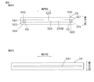
- FIG. 3 is an explanatory diagram illustrating a die and a feed block of the extrusion molding apparatus shown in FIG. 4A is a cross-sectional view taken along the line AA of the feed block shown in FIG. 2, and
- FIG. 4B is a side view of the die shown in FIG. 2 as viewed from the downstream side in the flow direction.
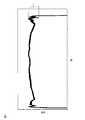
- FIG. 5 is a correlation diagram showing changes in the thickness of the base material obtained in the examples.
- FIG. 6 is a correlation diagram showing changes in the thickness of the base material obtained in the comparative example.
- the film F includes a base material S and a film C.
- the base material S has a first surface S1 and a second surface S2 in the thickness direction of the base material S.
- the coating film C is arranged on the first surface S1 of the base material S.
- the coating film C covers the first surface S1 of the base material S.
- the coating film C may be an easy-adhesive layer.
- the film F is an easy-adhesive film.
- the easy-adhesive film is used, for example, as a polarizing plate of an image display device such as a mobile device, a car navigation device, a monitor for a personal computer, and a television.
- the easy-adhesive film is used as a protective film that protects the polarizing element of the polarizing plate.
- the easy-adhesive film is bonded to the polarizing element via an adhesive layer.
- the easy-adhesive film is an easy-adhesive layer and is bonded to a polarizing element.
- the film F manufacturing system 1 includes an extrusion molding device 2, a first stretching device 4A as an example of a stretching device, a coating device 3, and a second stretching device as an example of a stretching device. It includes 4B, a slit processing device 5, a knurling processing device 6, and a winding device 7.
- Extrusion molding device 2 extrudes the base material S (extrusion molding step).
- the base material S extruded from the extrusion molding apparatus 2 has a sheet shape.
- the base material S is made of a thermoplastic resin.
- the thermoplastic resin include acrylic resin, polyolefin resin, cyclic polyolefin resin, polyester resin (polyethylene terephthalate, etc.), polycarbonate resin, polystyrene resin, polyamide resin, polyimide resin, acetate resin (diacetyl cellulose, triacetyl cellulose, etc.) and the like. Can be mentioned.
- the material of the base material S is preferably an acrylic resin.
- the acrylic resin may be an acrylic resin having a glutaric acid anhydride structure or an acrylic resin having a lactone ring structure.
- An acrylic resin having a glutaric acid anhydride structure and an acrylic resin having a lactone ring structure have high heat resistance, high transparency, and high mechanical strength, so that the polarizing plate has a high degree of polarization and excellent durability. Suitable for manufacturing.
- Acrylic resins having a glutaric acid anhydride structure are described in JP-A-2006-283013, JP-A-2006-335902, and JP-A-2006-274118.
- Acrylic resins having a lactone ring structure are described in JP-A-2000-230016, JP-A-2001-151814, JP-A-2002-120326, JP-A-2002-254544, and JP-A-2005-146084. Has been done.
- the base material S may contain a thermoplastic resin other than the acrylic resin in addition to the acrylic resin.
- a thermoplastic resin By containing another thermoplastic resin, it is possible to cancel the birefringence of the acrylic resin and obtain an easily adhesive film having excellent optical anisotropy. In addition, the mechanical strength of the easy-adhesive film can be improved.
- the base material S may contain additives such as antioxidants, stabilizers, reinforcing materials, ultraviolet absorbers, flame retardants, antistatic agents, colorants, fillers, plasticizers, lubricants and fillers. ..
- the first stretching device 4A heats the base material S obtained by the extrusion molding step and then stretches the base material S in the flow direction MD of the base material S (first stretching step).
- Coating device 3 applies a coating liquid to the first surface S1 of the base material S extruded by the extrusion molding step (coating step).
- the first surface S1 of the base material S may be subjected to surface treatment such as corona treatment and plasma treatment after the extrusion molding step and before the coating step.
- Examples of the coating device 3 include a bar coater, a gravure coater, a kiss coater, and the like.
- the coating liquid is an easy-adhesive composition for forming an easy-adhesive layer.
- the easy-adhesion layer contains a binder resin and fine particles.
- the binder resin examples include thermosetting resins such as urethane resin and epoxy resin, and thermoplastic resins such as acrylic resin and polyester resin.
- the binder resin is preferably a thermosetting resin.
- a plurality of types of binder resin can be used in combination.
- the fine particles include oxides such as silicon oxide (silica), titanium oxide (titania), aluminum oxide (alumina), and zirconium oxide (zirconia), and carbonates such as calcium carbonate, such as calcium silicate and silicate.
- oxides such as silicon oxide (silica), titanium oxide (titania), aluminum oxide (alumina), and zirconium oxide (zirconia)
- carbonates such as calcium carbonate, such as calcium silicate and silicate.
- examples include silicates such as aluminum silicate and magnesium silicate, such as silicate minerals such as talc and kaolin, such as phosphates such as calcium phosphate.
- the fine particles are preferably an oxide, more preferably silicon oxide. A plurality of types of fine particles can be used in combination.
- the coating liquid (easy-adhesion composition) contains a resin component, the above-mentioned fine particles, and a dispersion medium.
- the resin component forms the above-mentioned binder resin film (easy-adhesive layer) by the stretching step described later.
- the binder resin is a urethane resin
- examples of the resin component include an aqueous urethane resin.
- examples of the aqueous urethane resin include a non-reactive aqueous urethane resin which is an emulsion of a urethane resin, and for example, a reactive aqueous urethane resin which is an emulsion of a urethane resin in which an isocyanate group is protected with a blocking agent.
- the coating liquid may contain a urethane curing catalyst (such as triethylamine) and an isocyanate monomer.
- dispersion medium examples include water, for example, alcohols such as methanol and ethanol, and ketones such as acetone and methyl ethyl ketone.
- the second stretching device 4B dries the coating liquid applied by the coating step. As a result, the coating liquid becomes the above-mentioned film C. Further, the second stretching device 4B heats the base material S on which the coating film C is formed and then stretches the base material S in the width direction TD of the base material S (second stretching step). The width direction TD is orthogonal to the flow direction MD. By the second stretching step, the base material S on which the film C is formed is stretched, and the above-mentioned film F is obtained.
- Slit processing device 5 cuts the film F stretched by the stretching step to a predetermined width (slit step).
- Knurling apparatus 6 forms knurling at both ends in the width direction of the film F cut to a predetermined width by the slitting process (knurling process).
- Knar is formed by a laser.
- Knar may be formed by heated embossed rolls.
- Winding device 7 winds up the film F on which knurling is formed by the knurling step (winding step). When the winding process is completed, a roll of the film F can be obtained.
- the base material S formed by the extrusion molding apparatus 2 has a main body portion M and two reinforcing portions R1 and R2 in the width direction TD.
- the main body M extends in the width direction TD.
- the main body M is made of a brittle resin.
- the brittle resin is a resin that is easily broken when bent among the above-mentioned thermoplastic resins.
- the brittle resin refers to a resin having a folding resistance of less than 50 times in a folding strength test in which a load of JIS P 8115: 2001 is changed to a weight of 200 g.
- the folding resistance test is carried out under the following conditions using BE-202 (manufactured by Tester Sangyo) as a testing machine.
- the main body M is made of a brittle resin in an unstretched state.
- the unstretched state is a state after the extrusion molding step and before stretching the extrusion-molded base material S in the flow direction MD or the width direction TD.
- This embodiment is preferable when the folding resistance of the main body M is less than 10 times, and more preferably when the folding resistance of the main body M is less than 5.
- the brittle resin includes an acrylic resin.
- the reinforcing portion R1 reinforces one end of the main body portion M in the width direction TD.
- the reinforcing portion R1 is arranged at one end of the base material S in the width direction TD.
- the reinforcing portion R1 covers one end of the main body portion M in the width direction TD.
- the reinforcing portion R1 is made of a tough resin.
- the toughness resin refers to a resin having a folding resistance of 50 times or more in the above-mentioned folding strength test among the above-mentioned thermoplastic resins.
- the tough resin examples include a polycarbonate resin, a polyester resin, and a mixture of a polycarbonate resin and a polyester resin.
- the reinforcing portion R2 reinforces the other end of the main body portion M in the width direction TD.
- the reinforcing portion R2 is arranged at the other end of the base material S in the width direction TD.
- the reinforcing portion R2 is arranged on the opposite side of the reinforcing portion R1 with respect to the main body portion M in the width direction TD.
- the reinforcing portion R2 covers one end of the main body portion M in the width direction TD.
- the reinforcing portion R2 is made of a tough resin.
- the extrusion molding apparatus 2 includes a first barrel 21, a second barrel 22, a feed block 23, and a die 24.
- the first barrel 21 melts the first resin which is the raw material of the main body M of the base material S.
- the first resin becomes the first molten resin by being melted.
- the first resin include the above-mentioned brittle resin. That is, the first molten resin is a molten resin of a brittle resin.
- the viscosity of the first molten resin is, for example, 100 Pa ⁇ s or more, preferably 500 Pa ⁇ s or more, for example, 10,000 Pa ⁇ s or less, preferably 2000 Pa ⁇ s or less.
- the second barrel 22 melts the second resin which is the raw material of the reinforcing portions R1 and R2 of the base material S.
- the second resin becomes a second molten resin by being melted.
- the second resin include the above-mentioned toughness resin. That is, the second molten resin is a molten resin of a toughness resin.
- the viscosity of the second molten resin is, for example, 100 Pa ⁇ s or more, preferably 500 Pa ⁇ s or more, for example, 10,000 Pa ⁇ s or less, preferably 2000 Pa ⁇ s or less.
- Feed block 23 is connected to the first barrel 21 and the second barrel 22.
- the feed block 23 supplies the first molten resin from the first barrel 21 and the second molten resin from the second barrel 22 to the die 24.
- the feed block 23 has a first flow path 231, a second flow path 232, a third flow path 233, and a first manifold 234.
- the extrusion molding apparatus 2 has a first flow path 231, a second flow path 232, a third flow path 233, and a first manifold 234.
- the first flow path 231 is connected to the first barrel 21.
- the first molten resin is supplied from the first barrel 21 to the first flow path 231.
- the first molten resin supplied from the first barrel 21 passes through the first flow path 231.
- the first flow path 231 is connected to the first inflow port P1 of the first manifold 234.
- the first inlet P1 will be described later.
- the second flow path 232 is connected to the second barrel 22.
- the second molten resin is supplied from the second barrel 22 to the second flow path 232.
- the second molten resin supplied from the second barrel 22 passes through the second flow path 232.
- the second flow path 232 is connected to the second inflow port P2 of the first manifold 234.
- the second inlet P2 will be described later.
- the portion of the second flow path 232 connected to the second inflow port P2 extends along the flow direction MD. As a result, the second molten resin that has passed through the second flow path 232 can be supplied to the first manifold 234 along the flow direction MD.
- the third flow path 233 is connected to the second barrel 22.
- the second molten resin is supplied from the second barrel 22 to the third flow path 233.
- the second molten resin supplied from the second barrel 22 passes through the third flow path 233.
- the third flow path 233 is connected to the third inflow port P3 of the first manifold 234.
- the third inlet P3 will be described later.
- the portion of the third flow path 233 connected to the third inflow port extends along the flow direction MD. As a result, the second molten resin that has passed through the third flow path 233 can be supplied to the first manifold 234 along the flow direction MD.
- the first manifold 234 is arranged between the first flow path 231 and the die 24. In other words, the first manifold 234 is arranged between the first flow path 231 and the discharge port 241. The discharge port 241 will be described later.
- the first manifold 234 is connected to the first flow path 231.
- the first manifold 234 extends in the flow direction MD. In other words, the flow direction MD is a direction toward the discharge port 241 from the first inflow port P1.
- the first manifold 234 also extends in the width direction TD.
- the first manifold 234 spreads the first molten resin contained in the first manifold 234 in the width direction TD.
- the first manifold 234 has an upstream portion 234A, a downstream portion 234B, a first inlet P1, a second inlet P2, and a third inlet P3.
- Upstream portion The upstream portion 234A is connected to the first flow path 231.
- the upstream portion 234A is arranged between the downstream portion 234B and the first flow path 231 in the flow direction MD.
- the upstream portion 234A extends in the width direction TD from the first inflow port P1.
- the upstream portion 234A has an inner surface S11 and an inner surface S12 in the width direction.
- the inner surface S11 extends from the first inflow port P1 toward one side of the TD in the width direction.
- the inner surface S11 curves in the flow direction MD toward one side of the width direction TD.
- the inner surface S12 is arranged on the opposite side of the inner surface S11 with respect to the first inflow port P1 in the width direction TD.
- the inner surface S12 extends from the first inflow port P1 toward the other side in the width direction TD.
- the inner surface S12 curves in the flow direction MD toward the width direction TD.
- the upstream portion 234A spreads the first molten resin that has entered the first manifold 234 from the first inflow port P1 along the inner surface S11 and the inner surface S12 in the width direction TD.
- downstream portion 234B extends from the downstream end of the upstream portion 234A in the flow direction MD in the flow direction MD.
- the downstream portion 234B causes the first molten resin and the second molten resin in the first manifold 234 to flow in the flow direction MD.
- the length of the downstream portion 234B in the width direction TD is the same as the length of the downstream end of the upstream portion 234A in the width direction TD.
- One end and the other end of the downstream portion 234B in the width direction TD extend along the flow direction MD.
- One end of the downstream portion 234B in the width direction TD is one end of the first manifold 234 in the width direction TD, and the other end of the downstream portion 234B in the width direction TD is the other end of the first manifold 234 in the width direction TD. It is a department. That is, one end and the other end of the first manifold 234 in the width direction TD extend along the flow direction MD.
- the downstream portion 234B has a flat shape extending in the width direction TD when viewed from the flow direction MD.
- the first molten resin is spread by the first manifold 234 into a flat shape similar to the flat shape of the discharge port 241, and the second molten resin is spread on both ends of the widthwise TD of the first molten resin spread by the first manifold 234.
- the molten resin can be merged. Therefore, it is possible to further suppress the disturbance of the flow of the first molten resin and the flow of the second molten resin between the first manifold 234 and the discharge port 241. As a result, it is possible to further suppress the non-uniform thickness of the end portion of the extruded base material S.
- the downstream portion 234B has a rectangular shape extending in the width direction TD.
- the width of the downstream portion 234B in the thickness direction orthogonal to both the flow direction MD and the width direction TD is shorter than the diameter of the first inflow port P1.
- the flow velocity of the first molten resin in the downstream portion 234B of the first manifold 234 is, for example, 0.1 m / min or more, preferably 1 m / min or more, and for example, 10 m / min or less, preferably 5 m / min or less. Is.
- the first inflow port P1 communicates with the first flow path 231.
- the first inflow port P1 is arranged at the upstream end of the first manifold 234 in the flow direction MD.
- the first inflow port P1 is arranged between both ends of the first manifold 234 in the width direction TD.
- the first inlet P1 is arranged between the second inlet P2 and the third inlet P3 in the width direction TD.
- the first inflow port P1 is arranged in the center of the first manifold 234 in the width direction TD.
- the first inflow port P1 has a circular shape.
- the second inflow port P2 communicates with the second flow path 232.
- the second inflow port P2 is arranged downstream of the first inflow port P1 in the flow direction MD.
- the second inflow port P2 is arranged at one end of the first manifold 234 in the width direction TD.
- the second molten resin can be merged with the first molten resin at one end of the first manifold 234. Therefore, the second molten resin can be merged with the first molten resin expanded in the width direction by the first manifold 234. Therefore, it is possible to prevent the flow of the first molten resin and the flow of the second molten resin from being disturbed. As a result, it is possible to prevent the thickness of the end portion of the extruded base material S from becoming non-uniform.
- the second inflow port P2 is arranged at one end of the downstream portion 234B in the width direction TD.
- the first molten resin is spread in the width direction TD at the upstream portion 234A of the first manifold 234, one end of the width direction TD of the first molten resin flowing in the flow direction MD at the downstream portion 234B of the first manifold 234.
- the second molten resin can be merged with the portion. Therefore, it is possible to further suppress the disturbance of the flow of the first molten resin and the flow of the second molten resin at one end of the TD in the width direction. As a result, it is possible to further suppress the non-uniform thickness of the end portion of the extruded base material S.
- the second molten resin that has passed through the second inflow port P2 enters one end of the width direction TD of the downstream portion 234B, it is not spread in the width direction TD in the downstream portion 234B. Therefore, the second molten resin may not be formed into a desired shape in the downstream portion 234B. For example, if the shape of the downstream portion 234B is rectangular, while the shape of the second inlet P2 is circular, the end portion may be circular.
- the second inflow port P2 has a square shape. That is, the second molten resin enters one end of the rectangular downstream portion 234B in the width direction from the rectangular second inflow port P2. Therefore, when the second molten resin enters the downstream portion 234B from the second inflow port P2, the second molten resin has a shape that follows the shape of one end portion of the downstream portion 234B in the width direction TD. As a result, even if the second molten resin that has entered the downstream portion 234B from the second inflow port P2 is not spread in the width direction TD in the downstream portion 234B, the shape of one end of the width direction TD of the downstream portion 234B. It is possible to form an end along the line.
- the shape of the second inflow port P2 may be any shape that follows the shape of one end of the width direction TD of the downstream portion 234B, and is not limited to a square shape.
- the inner surface S31 on one side of the second inlet P2 in the width direction MD is flush with the inner surface S21 on one side of the downstream portion 234B in the width direction TD when viewed from the flow direction MD. Therefore, even if the second molten resin that has entered the downstream portion 234B from the second inflow port P2 does not spread in the width direction TD, the second molten resin follows the shape of one end of the width direction TD of the downstream portion 234B. Can be made. As a result, it is possible to form an end portion along the shape of one end portion of the downstream portion 234B in the width direction TD.
- the inner surface S31 does not have to be flush with the inner surface S21. There may be a step between the inner surface S31 and the inner surface S21 to such an extent that an end portion along the shape of one end portion of the downstream portion 234B in the width direction can be formed.
- the inner surface S32 on one side of the second inlet P2 in the thickness direction is flush with the inner surface S23 on one side of the downstream portion 234B in the thickness direction when viewed from the flow direction MD. Seen from the flow direction MD, the inner surface S33 on the other side of the second inflow port P2 in the thickness direction is flush with the inner surface S24 on the other side of the downstream portion 234B in the thickness direction. Therefore, it is possible to prevent the second molten resin that has entered the downstream portion 234B from the second inflow port P2 from spreading in the thickness direction. As a result, it is possible to further suppress the flow of the second molten resin from being disturbed when the second molten resin enters the downstream portion 234B from the second inflow port P2.
- the inner surface S32 does not have to be flush with the inner surface S23, and the inner surface S33 does not have to be flush with the inner surface S24. Even if there is a step between the inner surface S32 and the inner surface S23 and between the inner surface S33 and the inner surface S24 to the extent that an end portion can be formed along the shape of one end portion of the downstream portion 234B in the width direction TD. good.
- the flow velocity of the second molten resin at the second inflow port P2 is, for example, 0.5 times or more, preferably 0.7 times or more, the flow velocity of the first molten resin at the downstream portion 234B of the first manifold 234. For example, it is 1.5 times or less. Therefore, when the second molten resin is merged with the first molten resin at one end of the TD in the width direction, the flow velocity of the second molten resin can be brought close to the flow velocity of the first molten resin. As a result, it is possible to prevent the flow of the first molten resin and the flow of the second molten resin from being disturbed.
- the flow velocity of the second molten resin at the second inflow port P2 is, for example, 0.1 m / min or more, preferably 1 m / min or more, and for example, 10 m / min or less, preferably 5 m / min. Less than a minute.
- the third inflow port P3 communicates with the third flow path 233.
- the third inflow port P3 is arranged downstream of the first inflow port P1 in the flow direction MD.
- the third inflow port P3 is arranged at the other end of the first manifold 234 in the width direction TD.
- the second molten resin can be merged with the first molten resin at the other end of the first manifold 234. Therefore, the second molten resin can be merged with the first molten resin spread in the width direction TD by the first manifold 234. Therefore, it is possible to prevent the flow of the first molten resin and the flow of the second molten resin from being disturbed. As a result, it is possible to prevent the thickness of the end portion of the extruded base material S from becoming non-uniform.
- the third inflow port P3 is arranged at the other end of the downstream portion 234B in the width direction TD.
- the first molten resin is spread in the width direction TD at the upstream portion 234A of the first manifold 234, the other than the width direction TD of the first molten resin flowing in the flow direction MD at the downstream portion 234B of the first manifold 234.
- the second molten resin can be merged with the end portion. Therefore, it is possible to further suppress the disturbance of the flow of the first molten resin and the flow of the second molten resin at the other end of the TD in the width direction. As a result, it is possible to further suppress the non-uniform thickness of the end portion of the extruded base material S.
- the third inlet P3 has a rectangular shape like the second inlet P2. That is, the second molten resin enters the other end of the rectangular downstream portion 234B in the width direction TD from the rectangular third inflow port P3. Therefore, when the second molten resin enters the downstream portion 234B from the third inflow port P3, the second molten resin has a shape that follows the shape of the other end portion of the downstream portion 234B in the width direction TD. As a result, even if the second molten resin that has entered the downstream portion 234B from the third inflow port P3 is not spread in the width direction TD in the downstream portion 234B, the other end portion of the width direction TD of the downstream portion 234B It is possible to form an end portion that follows the shape.
- the shape of the third inflow port P3 may be any shape that follows the shape of the other end of the width direction TD of the downstream portion 234B, and is not limited to a square shape.
- the inner surface S41 on the other side of the third inlet P3 in the width direction MD is flush with the inner surface S22 on the other side of the downstream portion 234B in the width direction TD when viewed from the flow direction MD. Therefore, even if the second molten resin that has entered the downstream portion 234B from the third inflow port P3 does not spread in the width direction TD, the second molten resin can be subjected to the shape of the other end of the width direction TD of the downstream portion 234B. Can be followed. As a result, an end portion along the shape of the other end portion of the downstream portion 234B in the width direction TD can be formed.
- the inner surface S41 does not have to be flush with the inner surface S22. There may be a step between the inner surface S41 and the inner surface S22 to such an extent that an end portion along the shape of the other end of the widthwise TD of the downstream portion 234B can be formed.
- the inner surface S42 on one side of the third inflow port P3 in the thickness direction is flush with the inner surface S23 on one side of the downstream portion 234B in the thickness direction.
- the inner surface S43 on the other side of the third inflow port P3 in the thickness direction is flush with the inner surface S24 on the other side of the downstream portion 234B in the thickness direction. Therefore, it is possible to prevent the second molten resin that has entered the downstream portion 234B from the third inflow port P3 from spreading in the thickness direction. As a result, it is possible to further suppress the flow of the second molten resin from being disturbed when the second molten resin enters the downstream portion 234B from the third inflow port P3.
- the inner surface S42 does not have to be flush with the inner surface S23, and the inner surface S43 does not have to be flush with the inner surface S24. There is a step between the inner surface S42 and the inner surface S23 and between the inner surface S43 and the inner surface S24 to such an extent that an end portion along the shape of the other end of the widthwise TD of the downstream portion 234B can be formed. May be good.
- the flow velocity of the second molten resin at the third inflow port P3 is, for example, 0.5 times or more, preferably 0.7 times or more, the flow velocity of the first molten resin at the downstream portion 234B of the first manifold 234. For example, it is 1.5 times or less. Therefore, when the second molten resin is merged with the first molten resin at the other end of the TD in the width direction, the flow velocity of the second molten resin can be brought close to the flow velocity of the first molten resin. As a result, it is possible to prevent the flow of the first molten resin and the flow of the second molten resin from being disturbed.
- the flow velocity of the second molten resin at the third inflow port P3 is, for example, 0.1 m / min or more, preferably 1 m / min or more, and for example, 10 m / min or less, preferably 5 m / min. Less than a minute.
- the die 24 is connected to the feed block 23.
- the die 24 has a discharge port 241 and a second manifold 242.
- the extrusion molding apparatus 2 has a discharge port 241 and a second manifold 242.
- the discharge port 241 discharges the first molten resin and the second molten resin that have passed through the first manifold 234 and the second manifold 242.
- the discharge port 241 has a flat shape extending in the width direction TD. More specifically, the discharge port 241 has a rectangular shape extending in the width direction TD. The discharge port 241 is longer than the downstream portion 234B of the first manifold 234 in the width direction TD. The width of the discharge port 241 in the thickness direction is shorter than the width of the downstream portion 234B of the first manifold 234 in the thickness direction.
- the second manifold 242 is arranged between the first manifold 234 and the discharge port 241.
- the second manifold 242 communicates with the first manifold 234.
- the second manifold 242 extends in the flow direction MD.
- the second manifold 242 also extends in the width direction TD.
- the second manifold 242 is longer than the first manifold 234 in the width direction TD.
- the first molten resin and the second molten resin that have passed through the first manifold 234 can be further spread in the width direction TD by the second manifold 242.
- a large base material S can be formed in the width direction TD while suppressing the flow of the first molten resin and the flow of the second molten resin from being disturbed.
- the second manifold 242 has an upstream portion 242A and a downstream portion 242B.
- the upstream portion 242A communicates with the first manifold 234.
- the upstream portion 242A is arranged between the downstream portion 242B and the first manifold 234 in the flow direction MD.
- the upstream portion 242A extends from the first manifold 234 in the width direction TD.
- the upstream portion 242A has an inner surface S51 and an inner surface S52 in the width direction TD.
- the inner surface S51 extends from the first manifold 234 toward one side of the TD in the width direction.
- the inner surface S51 curves in the flow direction MD toward one side of the width direction TD.
- the inner surface S52 is arranged on the opposite side of the inner surface S51 with respect to the first manifold 234 in the width direction TD.
- the inner surface S52 extends from the first manifold 234 toward the other side in the width direction TD.
- the inner surface S52 curves in the flow direction MD toward the other side of the width direction TD.
- the upstream portion 242A spreads the first molten resin and the second molten resin that have entered the second manifold 242 from the first manifold 234 in the width direction TD along the inner surface S51 and the inner surface S52.
- the downstream portion 242B extends in the flow direction MD from the downstream end of the upstream portion 242A. As a result, the downstream portion 242B causes the first molten resin and the second molten resin in the second manifold 242 to flow in the flow direction MD.
- the downstream portion 242B has the same width as the downstream end of the upstream portion 242A. One end and the other end of the downstream portion 242B in the width direction TD extend along the flow direction MD. One end of the downstream portion 242B in the width direction TD is one end of the second manifold 242 in the width direction TD. The other end of the downstream portion 242B in the width direction TD is the other end of the second manifold 242 in the width direction TD.
- the downstream portion 234B has the same shape as the discharge port 241 when viewed from the flow direction MD.
- the downstream portion 234B leads to the discharge port 241.
- the extrusion molding apparatus 2 does not have to include the feed block 23.
- the first manifold 234 may be provided on the die 24.
- the extrusion molding apparatus 2 does not have to have the second manifold 242.
- the first manifold 234 may communicate with the discharge port 241.
- the first molten resin does not have to be a molten resin of a brittle resin.
- the first molten resin may be a molten resin having a toughness resin different from that of the second molten resin.
- the film F manufacturing system 1 does not have to be provided with the coating device 3.
- the film F manufacturing system 1 does not have to be provided with the first stretching device 4A.
- the base material S may be stretched (biaxial simultaneous stretching) in the flow direction MD and the width direction TD by the second stretching device 4B.
- the film F manufacturing system 1 does not have to include the first stretching device 4A and the second stretching device 4B. That is, the film F manufacturing system 1 does not have to stretch the film F. In that case, the film F may be cut into a fixed length and loaded without winding.
- the film F manufacturing system 1 does not have to be provided with the knurling processing device 6.
- a masking film may be attached to the film F and wound up.
- Example 1 As shown in FIG. 3, a base material was extruded by merging a molten resin of an acrylic resin (brittle resin) with a molten resin of polycarbonate (toughness resin) at both ends of a manifold of a feed block. During molding, the thickness of the molded substrate was continuously measured 100 times in the width direction using an in-line traverse infrared film thickness meter.
- the variation F1 in the thickness of the end portion of the base material of the example was smaller than the variation F2 of the thickness of the end portion of the substrate of the comparative example. That is, in the examples, it was possible to suppress the thickness of the end portion of the base material from becoming uneven as compared with the comparative example.
- the extrusion molding apparatus, the film manufacturing system, and the film manufacturing method of the present invention are used for manufacturing films such as easy-adhesive films.
Landscapes
- Engineering & Computer Science (AREA)
- Mechanical Engineering (AREA)
- Manufacturing & Machinery (AREA)
- Extrusion Moulding Of Plastics Or The Like (AREA)
Abstract
押出成形装置2は、第1溶融樹脂が通る第1流路231と、第2溶融樹脂が通る第2流路232および第3流路233と、第1マニホールド234と、第1マニホールド234を通った第1溶融樹脂および第2溶融樹脂を吐出する吐出口241とを有する。第2流路232は、幅方向TDにおける第1マニホールド234の一端部と接続する。第3流路233は、幅方向TDにおける第1マニホールド234の他端部と接続する。
Description
本発明は、押出成形装置、フィルムの製造システム、および、フィルムの製造方法に関する。
従来、中央が脆性樹脂からなり、両端が靱性樹脂からなるフィルムを押出成形する押出成形装置が知られている(例えば、特許文献1参照。)。
この押出成形装置は、脆性樹脂の溶融樹脂が流れる第1流路と、靭性樹脂の溶融樹脂が流れる第2流路と、第1流路と通じるマニホールドとを有する。第2流路は、第1流路の途中に合流する。
上記した特許文献1に記載されるような押出成形装置では、靭性樹脂の溶融樹脂は、第1流路の途中で、脆性樹脂の溶融樹脂と合流する。そのため、靭性樹脂の溶融樹脂が脆性樹脂の溶融樹脂と合流したときに、脆性樹脂の流れと靭性樹脂の流れとが乱れる。
その後、第1流路を通った溶融樹脂は、マニホールドで、幅方向に広げられる。このとき、脆性樹脂の流れと靭性樹脂の流れとの乱れが、更に助長される。
その結果、成形されたフィルムの端部の厚みが不均一になる場合がある。
本発明は、押出成形した基材の端部の厚みが不均一になることを抑制できる押出成形装置、フィルムの製造システム、および、フィルムの製造方法を提供する。
本発明[1]は、第1溶融樹脂が通る第1流路と、第2溶融樹脂が通る第2流路および第3流路と、前記第1流路と通じる第1流入口と、前記第2流路と通じる第2流入口と、前記第3流路と通じる第3流入口とを有する第1マニホールドと、前記第1マニホールドを通った前記第1溶融樹脂および前記第2溶融樹脂を吐出する吐出口とを有し、前記第1マニホールドは、前記第1流入口から前記吐出口へ向かう流れ方向に延び、かつ、前記流れ方向と直交する幅方向に延び、前記第1流入口は、前記流れ方向において前記第1マニホールドの上流端に配置され、かつ、前記幅方向において前記第1マニホールドの両端部の間に配置され、前記第2流入口は、前記流れ方向において前記第1流入口よりも下流に配置され、かつ、前記幅方向において前記第1マニホールドの一端部に配置され、前記第3流入口は、前記流れ方向において前記第1流入口よりも下流に配置され、かつ、前記幅方向において前記第1マニホールドの他端部に配置される、押出成形装置を含む。
このような構成によれば、第1マニホールドの両端部で、第1溶融樹脂に第2溶融樹脂を合流させることができる。
そのため、第1マニホールドで幅方向に広げられた第1溶融樹脂の両端部に、第2溶融樹脂を合流させることができる。
そのため、第1溶融樹脂の流れと第2溶融樹脂の流れとが乱れることを抑制できる。
その結果、押出成形した基材の端部の厚みが不均一になることを抑制できる。
本発明[2]は、前記幅方向における前記第1マニホールドの前記一端部および前記他端部が、前記流れ方向に沿って延び、前記第2流路のうちの前記第2流入口と接続される部分、および、前記第3流路のうちの前記第3流入口と接続される部分が、前記流れ方向に沿って延びる、上記[1]の押出成形装置を含む。
このような構成によれば、第2溶融樹脂を第1マニホールドに流れ方向に沿って供給でき、かつ、第1マニホールドに供給された第2溶融樹脂を流れ方向に沿って流すことができる。
そのため、第2溶融樹脂の流れが乱れることを、より抑制できる。
その結果、押出成形した基材の端部の厚みが不均一になることを、より抑制できる。
本発明[3]は、前記第1マニホールドが、前記第1流入口から前記幅方向に広がる上流部分と、前記流れ方向における前記上流部分の下流端から前記流れ方向に延びる下流部分とを有し、前記第2流入口が、前記幅方向において前記下流部分の一端部に配置され、前記第3流入口が、前記幅方向において前記下流部分の他端部に配置される、上記[1]または[2]の押出成形装置を含む。
このような構成によれば、第1マニホールドの上流部分で第1溶融樹脂を幅方向に広げた後、第1マニホールドの下流部分で、流れ方向に流れる第1溶融樹脂の幅方向両端に、第2溶融樹脂を合流させることができる。
そのため、第1溶融樹脂の流れと第2溶融樹脂の流れとが乱れることを、より抑制できる。
その結果、押出成形した基材の端部の厚みが不均一になることを、より抑制できる。
本発明[4]は、前記第1流入口が、円形状であり、前記吐出口が、前記幅方向に延びる扁平形状であり、前記第1マニホールドの前記下流部分が、前記流れ方向から見て、前記幅方向に延びる扁平形状である、上記[3]の押出成形装置を含む。
このような構成によれば、第1マニホールドによって、吐出口の扁平形状と近似した扁平形状に第1溶融樹脂を広げ、第1マニホールドによって広げられた第1溶融樹脂の幅方向両端に、第2溶融樹脂を合流させることができる。
そのため、第1マニホールドと吐出口との間で、第1溶融樹脂の流れと第2溶融樹脂の流れとが乱れることを、より抑制できる。
その結果、押出成形した基材の端部の厚みが不均一になることを、より抑制できる。
本発明[5]は、前記第2流入口が、前記下流部分の前記幅方向の一端部の形状に沿う形状を有し、前記第3流入口が、前記下流部分の前記幅方向の他端部の形状に沿う形状を有する、上記[4]の押出成形装置を含む。
このような構成によれば、第2溶融樹脂が第2流入口から下流部分に入った段階で、第2溶融樹脂は、下流部分の幅方向の一端部の形状に沿う形状を有している。
その結果、第2流入口から下流部分内に入った第2溶融樹脂が下流部分内で幅方向に広げられることがなくても、下流部分の幅方向の一端部の形状に沿った端部を形成できる。
同様に、第2溶融樹脂が第3流入口から下流部分に入った段階で、第2溶融樹脂は、下流部分の幅方向の他端部の形状に沿う形状を有している。
その結果、第3流入口から下流部分内に入った第2溶融樹脂が下流部分内で幅方向に広げられることがなくても、下流部分の幅方向の他端部の形状に沿った端部を形成できる。
本発明[6]は、前記流れ方向から見て、前記幅方向における前記第2流入口の一方側の内面が、前記幅方向における前記下流部分の一方側の内面と面一であり、前記流れ方向から見て、前記幅方向における前記第3流入口の他方側の内面が、前記幅方向における前記下流部分の他方側の内面と面一である、上記[5]の押出成形装置を含む。
このような構成によれば、第2流入口から下流部分に入った第2溶融樹脂が幅方向に広がることがなくても、第2溶融樹脂を、下流部分の幅方向の一端部の形状に沿わせることができる。
その結果、下流部分の幅方向の一端部の形状に沿った端部を形成できる。
また、第3流入口から下流部分に入った第2溶融樹脂が幅方向に広がることがなくても、第2溶融樹脂を、下流部分の幅方向の他端部の形状に沿わせることができる。
その結果、下流部分の幅方向の他端部の形状に沿った端部を形成できる。
本発明[7]は、前記流れ方向から見て、前記流れ方向および前記幅方向の両方と直交する厚み方向における前記第2流入口の一方側の内面が、前記厚み方向における前記下流部分の一方側の内面と面一であり、前記流れ方向から見て、前記厚み方向における前記第2流入口の他方側の内面が、前記厚み方向における前記下流部分の他方側の内面と面一であり、前記流れ方向から見て、前記厚み方向における前記第3流入口の一方側の内面が、前記厚み方向における前記下流部分の一方側の内面と面一であり、前記流れ方向から見て、前記厚み方向における前記第3流入口の他方側の内面が、前記厚み方向における前記下流部分の他方側の内面と面一である、上記[6]の押出成形装置を含む。
このような構成によれば、第2流入口から下流部分に入った第2溶融樹脂、および、第3流入口から下流部分に入った第2溶融樹脂が、厚み方向に広がることを防止できる。
そのため、第2溶融樹脂が第2流入口および第3流入口から下流部分に入るときに、第2溶融樹脂の流れが乱れることを、より抑制できる。
本発明[8]は、さらに、前記第1マニホールドと前記吐出口との間に配置され、前記第1マニホールドと通じる第2マニホールドを有し、前記第2マニホールドが、前記幅方向において前記第1マニホールドよりも長い、上記[1]~[7]のいずれか1つの押出成形装置を含む。
このような構成によれば、第1マニホールドを通った第1溶融樹脂および第2溶融樹脂を、第2マニホールドで、さらに、幅方向に広げることができる。
その結果、第1溶融樹脂の流れと第2溶融樹脂の流れとが乱れることを抑制しつつ、幅方向に大きな基材を成形できる。
本発明[9]は、前記第1マニホールドを有するフィードブロックと、前記吐出口を有し、前記フィードブロックと接続されるダイとを備える、上記[8]の押出成形装置を含む。
本発明[10]は、前記ダイが、前記第2マニホールドを、さらに有する、上記[9]の押出成形装置を含む。
本発明[11]は、前記第2流入口における前記第2溶融樹脂の流速、および、前記第3流入口における前記第2溶融樹脂の流速が、前記第1マニホールドにおける前記第1溶融樹脂の流速の0.5倍以上、2.0倍以下である、上記[1]~[10]のいずれか1つの押出成形装置を含む。
このような構成によれば、第1溶融樹脂に第2溶融樹脂を合流させるときに、第2溶融樹脂の流速を第1溶融樹脂の流速に近づけることができる。
その結果、第1溶融樹脂の流れと第2溶融樹脂の流れとが乱れることを抑制できる。
本発明[12]は、前記第2流入口における前記第2溶融樹脂の流速、前記第3流入口における前記第2溶融樹脂の流速、および、前記第1マニホールドにおける前記第1溶融樹脂の流速が、0.1m/分以上、10m/分以下である、上記[11]の押出成形装置を含む。
本発明[13]は、前記第1溶融樹脂および前記第2溶融樹脂の粘度が、100Pa・s以上、10000Pa・s以下である、上記[1]~[12]のいずれか1つの押出成形装置を含む。
本発明[14]は、前記第1溶融樹脂が、脆性樹脂の溶融樹脂であり、前記第2溶融樹脂が、靭性樹脂の溶融樹脂である、上記[1]~[13]のいずれか1つの押出成形装置を含む。
このような構成によれば、成形された基材において、脆性樹脂からなる部分の幅方向両端を、靭性樹脂で補強できる。
本発明[15]は、上記[1]~[14]のいずれか1つの押出成形装置と、前記押出成形装置によって押出成形された基材を延伸する延伸装置とを備える、フィルムの製造システムを含む。
本発明[16]は、上記[1]~[14]のいずれか1つの押出成形装置で基材を押出成形する押出成形工程と、前記押出成形工程によって得られた前記基材を延伸する延伸工程とを含む、フィルムの製造方法を含む。
本発明の押出成形装置、フィルムの製造システム、および、フィルムの製造方法によれば、押出成形した基材の端部の厚みが不均一になることを抑制できる。
1.フィルムの製造システム
フィルムFの製造システム1について説明する。
フィルムFの製造システム1について説明する。
図1に示すように、フィルムFは、基材Sと、被膜Cとを備える。基材Sは、基材Sの厚み方向において、第1面S1と、第2面S2とを有する。被膜Cは、基材Sの第1面S1の上に配置される。被膜Cは、基材Sの第1面S1を覆う。被膜Cは、易接着層であってもよい。被膜Cが易接着層である場合、フィルムFは、易接着フィルムである。易接着フィルムは、例えば、モバイル機器、カーナビゲーション装置、パソコン用モニタ、テレビなどの画像表示装置の偏光板に使用される。詳しくは、易接着フィルムは、偏光板の偏光子を保護する保護フィルムとして使用される。易接着フィルムは、接着剤層を介して、偏光子と貼り合わされる。易接着フィルムは、易接着層で、偏光子と貼り合わされる。
図2に示すように、フィルムFの製造システム1は、押出成形装置2と、延伸装置の一例としての第1延伸装置4Aと、塗工装置3と、延伸装置の一例としての第2延伸装置4Bと、スリット加工装置5と、ナーリング加工装置6と、巻取装置7とを備える。
(1)押出成形装置
押出成形装置2は、基材Sを押出成形する(押出成形工程)。押出成形装置2から押し出された基材Sは、シート形状を有する。
押出成形装置2は、基材Sを押出成形する(押出成形工程)。押出成形装置2から押し出された基材Sは、シート形状を有する。
基材Sは、熱可塑性樹脂からなる。熱可塑性樹脂としては、例えば、アクリル樹脂、ポリオレフィン樹脂、環状ポリオレフィン樹脂、ポリエステル樹脂(ポリエチレンテレフタレートなど)、ポリカーボネート樹脂、ポリスチレン樹脂、ポリアミド樹脂、ポリイミド樹脂、アセテート樹脂(ジアセチルセルロース、トリアセチルセルロースなど)などが挙げられる。
偏光子の保護フィルムとして使用される易接着フィルムを製造する場合、基材Sの材料として、好ましくは、アクリル樹脂が挙げられる。
また、偏光子の保護フィルムとして使用される易接着フィルムを製造する場合、アクリル樹脂は、グルタル酸無水物構造を有するアクリル樹脂、ラクトン環構造を有するアクリル樹脂であってもよい。グルタル酸無水物構造を有するアクリル樹脂、および、ラクトン環構造を有するアクリル樹脂は、高い耐熱性、高い透明性、および高い機械的強度を有するため、偏光度が高くかつ耐久性に優れる偏光板の製造に適する。グルタル酸無水物構造を有するアクリル樹脂は、特開2006-283013号公報、特開2006-335902号公報、特開2006-274118号公報に記載されている。ラクトン環構造を有するアクリル樹脂は、特開2000-230016号公報、特開2001-151814号公報、特開2002-120326号公報、特開2002-254544号公報、特開2005-146084号公報に記載されている。
また、基材Sは、アクリル樹脂に加えて、アクリル樹脂以外の他の熱可塑性樹脂を含有してもよい。他の熱可塑性樹脂を含有することにより、アクリル樹脂の複屈折を打ち消して、光学等方性に優れる易接着フィルムを得ることができる。また、易接着フィルムの機械強度を向上させることもできる。
なお、基材Sは、酸化防止剤、安定剤、補強材、紫外線吸収剤、難燃剤、帯電防止剤、着色剤、充填剤、可塑剤、滑剤、フィラーなどの添加剤を含有してもよい。
(2)第1延伸装置
第1延伸装置4Aは、押出成形工程によって得られた基材Sを、加熱した後、基材Sの流れ方向MDに延伸する(第1延伸工程)。
第1延伸装置4Aは、押出成形工程によって得られた基材Sを、加熱した後、基材Sの流れ方向MDに延伸する(第1延伸工程)。
(3)塗工装置
塗工装置3は、押出成形工程によって押出成形された基材Sの第1面S1に、塗工液を塗布する(塗布工程)。なお、基材Sの第1面S1には、押出成形工程の後、塗布工程の前に、コロナ処理、プラズマ処理などの表面処理が、施されてもよい。
塗工装置3は、押出成形工程によって押出成形された基材Sの第1面S1に、塗工液を塗布する(塗布工程)。なお、基材Sの第1面S1には、押出成形工程の後、塗布工程の前に、コロナ処理、プラズマ処理などの表面処理が、施されてもよい。
塗工装置3としては、例えば、バーコーター、グラビアコーター、キスコーターなどが挙げられる。
易接着フィルムを製造する場合、塗工液は、易接着層を形成するための易接着組成物である。
易接着層は、バインダ樹脂と、微粒子とを含有する。
バインダ樹脂としては、例えば、ウレタン樹脂、エポキシ樹脂などの熱硬化性樹脂、例えば、アクリル樹脂、ポリエステル樹脂などの熱可塑性樹脂が挙げられる。易接着フィルムが偏光子の保護フィルムとして使用される場合、バインダ樹脂は、好ましくは、熱硬化性樹脂である。バインダ樹脂は、複数種類を併用できる。
微粒子としては、例えば、酸化ケイ素(シリカ)、酸化チタン(チタニア)、酸化アルミニウム(アルミナ)、酸化ジルコニウム(ジルコニア)などの酸化物、例えば、炭酸カルシウムなどの炭酸塩、例えば、ケイ酸カルシウム、ケイ酸アルミニウム、ケイ酸マグネシウムなどのケイ酸塩、例えば、タルク、カオリンなどのケイ酸塩鉱物、例えば、リン酸カルシウムなどのリン酸塩などが挙げられる。易接着フィルムが偏光子の保護フィルムとして使用される場合、微粒子は、好ましくは、酸化物、より好ましくは、酸化ケイ素である。微粒子は、複数種類を併用できる。
塗工液(易接着組成物)は、樹脂成分と、上記した微粒子と、分散媒とを含有する。
樹脂成分は、後述する延伸工程によって、上記したバインダ樹脂の被膜(易接着層)を形成する。バインダ樹脂がウレタン樹脂である場合、樹脂成分としては、例えば、水系ウレタン樹脂が挙げられる。水系ウレタン樹脂としては、例えば、ウレタン樹脂の乳化物である非反応型水系ウレタン樹脂、例えば、イソシアネート基をブロック剤で保護したウレタン樹脂の乳化物である反応型水系ウレタン樹脂などが挙げられる。バインダ樹脂がウレタン樹脂である場合、塗工液は、ウレタン硬化触媒(トリエチルアミンなど)、イソシアネートモノマーを含有してもよい。
分散媒としては、例えば、水、例えば、メタノール、エタノールなどのアルコール、例えば、アセトン、メチルエチルケトンなどのケトンなどが挙げられる。
(4)第2延伸装置
第2延伸装置4Bは、塗工工程によって塗布された塗工液を乾燥する。これにより、塗工液が上記した被膜Cになる。また、第2延伸装置4Bは、被膜Cが形成された基材Sを、加熱した後、基材Sの幅方向TDに延伸する(第2延伸工程)。幅方向TDは、流れ方向MDと直交する。第2延伸工程により、被膜Cが形成された基材Sが延伸され、上記したフィルムFが得られる。
第2延伸装置4Bは、塗工工程によって塗布された塗工液を乾燥する。これにより、塗工液が上記した被膜Cになる。また、第2延伸装置4Bは、被膜Cが形成された基材Sを、加熱した後、基材Sの幅方向TDに延伸する(第2延伸工程)。幅方向TDは、流れ方向MDと直交する。第2延伸工程により、被膜Cが形成された基材Sが延伸され、上記したフィルムFが得られる。
(5)スリット加工装置
スリット加工装置5は、延伸工程によって延伸されたフィルムFを、所定の幅に切断する(スリット工程)。
スリット加工装置5は、延伸工程によって延伸されたフィルムFを、所定の幅に切断する(スリット工程)。
(6)ナーリング加工装置
ナーリング加工装置6は、スリット工程によって所定の幅に切断されたフィルムFの幅方向両端に、ナールを形成する(ナーリング工程)。ナールは、レーザーによって形成される。ナールは、加熱されたエンボスロールによって形成されてもよい。
ナーリング加工装置6は、スリット工程によって所定の幅に切断されたフィルムFの幅方向両端に、ナールを形成する(ナーリング工程)。ナールは、レーザーによって形成される。ナールは、加熱されたエンボスロールによって形成されてもよい。
(7)巻取装置
巻取装置7は、ナーリング工程によってナールが形成されたフィルムFを巻き取る(巻取工程)。巻取工程が完了することにより、フィルムFのロールを得ることができる。
巻取装置7は、ナーリング工程によってナールが形成されたフィルムFを巻き取る(巻取工程)。巻取工程が完了することにより、フィルムFのロールを得ることができる。
2.押出成形装置の詳細
次に、押出成形装置2の詳細について説明する。
次に、押出成形装置2の詳細について説明する。
図3に示すように、本実施形態では、押出成形装置2によって成形された基材Sは、幅方向TDにおいて、本体部Mと、2つの補強部R1、R2とを有する。
本体部Mは、幅方向TDに延びる。本体部Mは、脆性樹脂からなる。
脆性樹脂とは、上記した熱可塑性樹脂のうち、曲げられたときに割れやすい樹脂である。詳しくは、脆性樹脂とは、JIS P 8115:2001における荷重を200g重に変えた耐折強さ試験において、耐折回数が50回未満である樹脂をいう。
耐折強さ試験は、試験機として、BE-202(テスター産業製)を使用し、以下の条件で実施する。
<耐折強さ試験条件>
試験片のサイズ:幅15mm、長さ110mm
試験速度:175cpm
折曲げ角度:135°
荷重:200g重
折曲げクランプの曲率半径R:0.38mm
折曲げクランプの開き:0.25mm
本実施形態では、本体部Mは、未延伸の状態で、脆性樹脂からなる。未延伸の状態とは、押出成形工程の後、押出成形された基材Sを流れ方向MDまたは幅方向TDに延伸する前の状態である。
試験片のサイズ:幅15mm、長さ110mm
試験速度:175cpm
折曲げ角度:135°
荷重:200g重
折曲げクランプの曲率半径R:0.38mm
折曲げクランプの開き:0.25mm
本実施形態では、本体部Mは、未延伸の状態で、脆性樹脂からなる。未延伸の状態とは、押出成形工程の後、押出成形された基材Sを流れ方向MDまたは幅方向TDに延伸する前の状態である。
本実施形態は、本体部Mの耐折回数が10回未満である場合に好ましく、本体部Mの耐折回数が5回未満である場合に、より好ましい。
具体的には、脆性樹脂としては、アクリル樹脂が挙げられる。
補強部R1は、幅方向TDにおける本体部Mの一端部を補強する。補強部R1は、幅方向TDにおいて、基材Sの一端部に配置される。補強部R1は、幅方向TDにおける本体部Mの一端部を覆う。補強部R1は、靭性樹脂からなる。
靭性樹脂とは、上記した熱可塑性樹脂のうち、上記した耐折強さ試験において、耐折回数が50回以上である樹脂をいう。
靭性樹脂としては、例えば、ポリカーボネート樹脂、ポリエステル樹脂、ポリカーボネート樹脂とポリエステル樹脂との混合物などが挙げられる。
補強部R2は、幅方向TDにおける本体部Mの他端部を補強する。補強部R2は、幅方向TDにおいて、基材Sの他端部に配置される。補強部R2は、幅方向TDにおいて、本体部Mに対して、補強部R1の反対側に配置される。補強部R2は、幅方向TDにおける本体部Mの一端部を覆う。補強部R2は、靭性樹脂からなる。
詳しくは、押出成形装置2は、第1バレル21と、第2バレル22と、フィードブロック23と、ダイ24とを備える。
(1)第1バレル
第1バレル21は、基材Sの本体部Mの原料である第1樹脂を溶融する。第1樹脂は、溶融されることにより、第1溶融樹脂になる。第1樹脂としては、例えば、上記した脆性樹脂が挙げられる。つまり、第1溶融樹脂は、脆性樹脂の溶融樹脂である。
第1バレル21は、基材Sの本体部Mの原料である第1樹脂を溶融する。第1樹脂は、溶融されることにより、第1溶融樹脂になる。第1樹脂としては、例えば、上記した脆性樹脂が挙げられる。つまり、第1溶融樹脂は、脆性樹脂の溶融樹脂である。
第1溶融樹脂の粘度は、例えば、100Pa・s以上、好ましくは、500Pa・s以上、例えば、10000Pa・s以下、好ましくは、2000Pa・s以下である。
(2)第2バレル
第2バレル22は、基材Sの補強部R1、R2の原料である第2樹脂を溶融する。第2樹脂は、溶融されることにより、第2溶融樹脂になる。第2樹脂としては、上記した靭性樹脂が挙げられる。つまり、第2溶融樹脂は、靭性樹脂の溶融樹脂である。
第2バレル22は、基材Sの補強部R1、R2の原料である第2樹脂を溶融する。第2樹脂は、溶融されることにより、第2溶融樹脂になる。第2樹脂としては、上記した靭性樹脂が挙げられる。つまり、第2溶融樹脂は、靭性樹脂の溶融樹脂である。
第2溶融樹脂の粘度は、例えば、100Pa・s以上、好ましくは、500Pa・s以上、例えば、10000Pa・s以下、好ましくは、2000Pa・s以下である。
(3)フィードブロック
フィードブロック23は、第1バレル21および第2バレル22と接続される。フィードブロック23は、第1バレル21からの第1溶融樹脂、および、第2バレル22からの第2溶融樹脂を、ダイ24に供給する。
フィードブロック23は、第1バレル21および第2バレル22と接続される。フィードブロック23は、第1バレル21からの第1溶融樹脂、および、第2バレル22からの第2溶融樹脂を、ダイ24に供給する。
フィードブロック23は、第1流路231と、第2流路232と、第3流路233と、第1マニホールド234とを有する。言い換えると、押出成形装置2は、第1流路231と、第2流路232と、第3流路233と、第1マニホールド234とを有する。
(3-1)第1流路
第1流路231は、第1バレル21と接続される。第1流路231には、第1バレル21から第1溶融樹脂が供給される。第1バレル21から供給された第1溶融樹脂は、第1流路231を通る。第1流路231は、第1マニホールド234の第1流入口P1に接続される。第1流入口P1については、後で説明する。
第1流路231は、第1バレル21と接続される。第1流路231には、第1バレル21から第1溶融樹脂が供給される。第1バレル21から供給された第1溶融樹脂は、第1流路231を通る。第1流路231は、第1マニホールド234の第1流入口P1に接続される。第1流入口P1については、後で説明する。
(3-2)第2流路
第2流路232は、第2バレル22と接続される。第2流路232には、第2バレル22から第2溶融樹脂が供給される。第2バレル22から供給された第2溶融樹脂は、第2流路232を通る。第2流路232は、第1マニホールド234の第2流入口P2に接続される。第2流入口P2については、後で説明する。第2流路232のうちの第2流入口P2と接続される部分は、流れ方向MDに沿って延びる。これにより、第2流路232を通った第2溶融樹脂を、第1マニホールド234に、流れ方向MDに沿って供給できる。
第2流路232は、第2バレル22と接続される。第2流路232には、第2バレル22から第2溶融樹脂が供給される。第2バレル22から供給された第2溶融樹脂は、第2流路232を通る。第2流路232は、第1マニホールド234の第2流入口P2に接続される。第2流入口P2については、後で説明する。第2流路232のうちの第2流入口P2と接続される部分は、流れ方向MDに沿って延びる。これにより、第2流路232を通った第2溶融樹脂を、第1マニホールド234に、流れ方向MDに沿って供給できる。
(3-3)第3流路
第3流路233は、第2バレル22と接続される。第3流路233には、第2バレル22から第2溶融樹脂が供給される。第2バレル22から供給された第2溶融樹脂は、第3流路233を通る。第3流路233は、第1マニホールド234の第3流入口P3に接続される。第3流入口P3については、後で説明する。第3流路233のうちの第3流入口と接続される部分は、流れ方向MDに沿って延びる。これにより、第3流路233を通った第2溶融樹脂を、第1マニホールド234に、流れ方向MDに沿って供給できる。
第3流路233は、第2バレル22と接続される。第3流路233には、第2バレル22から第2溶融樹脂が供給される。第2バレル22から供給された第2溶融樹脂は、第3流路233を通る。第3流路233は、第1マニホールド234の第3流入口P3に接続される。第3流入口P3については、後で説明する。第3流路233のうちの第3流入口と接続される部分は、流れ方向MDに沿って延びる。これにより、第3流路233を通った第2溶融樹脂を、第1マニホールド234に、流れ方向MDに沿って供給できる。
(3-4)第1マニホールド
第1マニホールド234は、第1流路231とダイ24との間に配置される。言い換えると、第1マニホールド234は、第1流路231と吐出口241との間に配置される。吐出口241については、後で説明する。第1マニホールド234は、第1流路231と接続される。第1マニホールド234は、流れ方向MDに延びる。流れ方向MDは、言い換えると、第1流入口P1から吐出口241へ向かう方向である。第1マニホールド234は、幅方向TDにも延びる。第1マニホールド234は、第1マニホールド234に入った第1溶融樹脂を、幅方向TDに広げる。
第1マニホールド234は、第1流路231とダイ24との間に配置される。言い換えると、第1マニホールド234は、第1流路231と吐出口241との間に配置される。吐出口241については、後で説明する。第1マニホールド234は、第1流路231と接続される。第1マニホールド234は、流れ方向MDに延びる。流れ方向MDは、言い換えると、第1流入口P1から吐出口241へ向かう方向である。第1マニホールド234は、幅方向TDにも延びる。第1マニホールド234は、第1マニホールド234に入った第1溶融樹脂を、幅方向TDに広げる。
詳しくは、第1マニホールド234は、上流部分234Aと、下流部分234Bと、第1流入口P1と、第2流入口P2と、第3流入口P3とを有する。
(3-4-1)上流部分
上流部分234Aは、第1流路231と接続される。上流部分234Aは、流れ方向MDにおいて、下流部分234Bと第1流路231との間に配置される。上流部分234Aは、第1流入口P1から幅方向TDに広がる。
上流部分234Aは、第1流路231と接続される。上流部分234Aは、流れ方向MDにおいて、下流部分234Bと第1流路231との間に配置される。上流部分234Aは、第1流入口P1から幅方向TDに広がる。
詳しくは、上流部分234Aは、幅方向において、内面S11と、内面S12とを有する。内面S11は、第1流入口P1から幅方向TDの一方側に向かって延びる。内面S11は、幅方向TDの一方側に向かうにつれて、流れ方向MDへ湾曲する。内面S12は、幅方向TDにおいて、第1流入口P1に対して、内面S11の反対側に配置される。内面S12は、第1流入口P1から幅方向TDの他方側に向かって延びる。内面S12は、幅方向TDに向かうにつれて、流れ方向MDへ湾曲する。上流部分234Aは、第1流入口P1から第1マニホールド234に入った第1溶融樹脂を、内面S11および内面S12に沿って、幅方向TDに広げる。
(3-4-2)下流部分
下流部分234Bは、流れ方向MDにおける上流部分234Aの下流端から、流れ方向MDに延びる。これにより、下流部分234Bは、第1マニホールド234内の第1溶融樹脂および第2溶融樹脂を、流れ方向MDに流す。幅方向TDにおける下流部分234Bの長さは、幅方向TDにおける上流部分234Aの下流端の長さと同じである。幅方向TDにおける下流部分234Bの一端部および他端部は、流れ方向MDに沿って延びる。幅方向TDにおける下流部分234Bの一端部は、幅方向TDにおける第1マニホールド234の一端部であり、幅方向TDにおける下流部分234Bの他端部は、幅方向TDにおける第1マニホールド234の他端部である。つまり、幅方向TDにおける第1マニホールド234の一端部および他端部は、流れ方向MDに沿って延びる。
下流部分234Bは、流れ方向MDにおける上流部分234Aの下流端から、流れ方向MDに延びる。これにより、下流部分234Bは、第1マニホールド234内の第1溶融樹脂および第2溶融樹脂を、流れ方向MDに流す。幅方向TDにおける下流部分234Bの長さは、幅方向TDにおける上流部分234Aの下流端の長さと同じである。幅方向TDにおける下流部分234Bの一端部および他端部は、流れ方向MDに沿って延びる。幅方向TDにおける下流部分234Bの一端部は、幅方向TDにおける第1マニホールド234の一端部であり、幅方向TDにおける下流部分234Bの他端部は、幅方向TDにおける第1マニホールド234の他端部である。つまり、幅方向TDにおける第1マニホールド234の一端部および他端部は、流れ方向MDに沿って延びる。
図4Aに示すように、下流部分234Bは、流れ方向MDから見て、幅方向TDに延びる扁平形状である。これにより、第1マニホールド234によって、吐出口241の扁平形状と近似した扁平形状に第1溶融樹脂を広げ、第1マニホールド234によって広げられた第1溶融樹脂の幅方向TDの両端に、第2溶融樹脂を合流させることができる。そのため、第1マニホールド234と吐出口241との間で、第1溶融樹脂の流れと第2溶融樹脂の流れとが乱れることを、より抑制できる。その結果、押出成形した基材Sの端部の厚みが不均一になることを、より抑制できる。より具体的には、下流部分234Bは、幅方向TDに延びる長方形状である。
なお、流れ方向MDおよび幅方向TDの両方と直交する厚み方向における下流部分234Bの幅は、第1流入口P1の直径よりも短い。
第1マニホールド234の下流部分234Bにおける第1溶融樹脂の流速は、例えば、0.1m/分以上、好ましくは、1m/分以上であり、例えば、10m/分以下、好ましくは、5m/分以下である。
(3-4-3)第1流入口
図3に示すように、第1流入口P1は、第1流路231と通じる。第1流入口P1は、流れ方向MDにおいて、第1マニホールド234の上流端に配置される。第1流入口P1は、幅方向TDにおいて、第1マニホールド234の両端部の間に配置される。第1流入口P1は、幅方向TDにおいて、第2流入口P2と第3流入口P3との間に配置される。第1流入口P1は、幅方向TDにおいて、第1マニホールド234の中央に配置される。第1流入口P1は、円形状である。
図3に示すように、第1流入口P1は、第1流路231と通じる。第1流入口P1は、流れ方向MDにおいて、第1マニホールド234の上流端に配置される。第1流入口P1は、幅方向TDにおいて、第1マニホールド234の両端部の間に配置される。第1流入口P1は、幅方向TDにおいて、第2流入口P2と第3流入口P3との間に配置される。第1流入口P1は、幅方向TDにおいて、第1マニホールド234の中央に配置される。第1流入口P1は、円形状である。
(3-4-4)第2流入口
第2流入口P2は、第2流路232と通じる。第2流入口P2は、流れ方向MDにおいて、第1流入口P1よりも下流に配置される。第2流入口P2は、幅方向TDにおいて、第1マニホールド234の一端部に配置される。これにより、第1マニホールド234の一端部で、第1溶融樹脂に第2溶融樹脂を合流させることができる。そのため、第1マニホールド234で幅方向に広げられた第1溶融樹脂に、第2溶融樹脂を合流させることができる。そのため、第1溶融樹脂の流れと第2溶融樹脂の流れとが乱れることを抑制できる。その結果、押出成形した基材Sの端部の厚みが不均一になることを抑制できる。
第2流入口P2は、第2流路232と通じる。第2流入口P2は、流れ方向MDにおいて、第1流入口P1よりも下流に配置される。第2流入口P2は、幅方向TDにおいて、第1マニホールド234の一端部に配置される。これにより、第1マニホールド234の一端部で、第1溶融樹脂に第2溶融樹脂を合流させることができる。そのため、第1マニホールド234で幅方向に広げられた第1溶融樹脂に、第2溶融樹脂を合流させることができる。そのため、第1溶融樹脂の流れと第2溶融樹脂の流れとが乱れることを抑制できる。その結果、押出成形した基材Sの端部の厚みが不均一になることを抑制できる。
詳しくは、図4Aに示すように、第2流入口P2は、幅方向TDにおいて、下流部分234Bの一端部に配置される。これにより、第1マニホールド234の上流部分234Aで第1溶融樹脂を幅方向TDに広げた後、第1マニホールド234の下流部分234Bで、流れ方向MDに流れる第1溶融樹脂の幅方向TDの一端部に、第2溶融樹脂を合流させることができる。そのため、幅方向TDの一端部において、第1溶融樹脂の流れと第2溶融樹脂の流れとが乱れることを、より抑制できる。その結果、押出成形した基材Sの端部の厚みが不均一になることを、より抑制できる。
ここで、第2流入口P2を通った第2溶融樹脂は、下流部分234Bの幅方向TDの一端部に入るので、下流部分234B内において、幅方向TDに広げられることがない。そのため、第2溶融樹脂を、下流部分234B内で、所望の形状に成形できない可能性がある。例えば、下流部分234Bの形状が長方形状であるのに対して、第2流入口P2の形状が円形状である場合、端部が円形状になってしまう可能性がある。
この点、第2流入口P2は、四角形状である。つまり、第2溶融樹脂は、四角形状の第2流入口P2から、長方形状の下流部分234Bの幅方向TDの一端部に入る。そのため、第2溶融樹脂が第2流入口P2から下流部分234Bに入った段階で、第2溶融樹脂は、下流部分234Bの幅方向TDの一端部の形状に沿う形状を有している。その結果、第2流入口P2から下流部分234B内に入った第2溶融樹脂が下流部分234B内で幅方向TDに広げられることがなくても、下流部分234Bの幅方向TDの一端部の形状に沿った端部を形成できる。
なお、第2流入口P2の形状は、下流部分234Bの幅方向TDの一端部の形状に沿う形状であればよく、四角形状に限られない。
好ましくは、流れ方向MDから見て、幅方向TDにおける第2流入口P2の一方側の内面S31は、幅方向TDにおける下流部分234Bの一方側の内面S21と面一である。そのため、第2流入口P2から下流部分234Bに入った第2溶融樹脂が幅方向TDに広がることがなくても、第2溶融樹脂を、下流部分234Bの幅方向TDの一端部の形状に沿わせることができる。その結果、下流部分234Bの幅方向TDの一端部の形状に沿った端部を形成できる。
なお、内面S31は、内面S21と面一でなくてもよい。内面S31と内面S21との間には、下流部分234Bの幅方向TDの一端部の形状に沿った端部を形成できる程度に、段差があってもよい。
流れ方向MDから見て、厚み方向における第2流入口P2の一方側の内面S32は、厚み方向における下流部分234Bの一方側の内面S23と面一である。流れ方向MDから見て、厚み方向における第2流入口P2の他方側の内面S33は、厚み方向における下流部分234Bの他方側の内面S24と面一である。そのため、第2流入口P2から下流部分234Bに入った第2溶融樹脂が、厚み方向に広がることを防止できる。その結果、第2溶融樹脂が第2流入口P2から下流部分234Bに入るときに、第2溶融樹脂の流れが乱れることを、より抑制できる。
なお、内面S32は、内面S23と面一でなくてもよく、内面S33は、内面S24と面一でなくてもよい。内面S32と内面S23との間、および、内面S33と内面S24との間には、下流部分234Bの幅方向TDの一端部の形状に沿った端部を形成できる程度に、段差があってもよい。
第2流入口P2における第2溶融樹脂の流速は、第1マニホールド234の下流部分234Bにおける第1溶融樹脂の流速の、例えば、0.5倍以上、好ましくは、0.7倍以上であり、例えば、1.5倍以下である。そのため、幅方向TDの一端部において、第1溶融樹脂に第2溶融樹脂を合流させるときに、第2溶融樹脂の流速を第1溶融樹脂の流速に近づけることができる。その結果、第1溶融樹脂の流れと第2溶融樹脂の流れとが乱れることを抑制できる。
具体的には、第2流入口P2における第2溶融樹脂の流速は、例えば、0.1m/分以上、好ましくは、1m/分以上であり、例えば、10m/分以下、好ましくは、5m/分以下である。
(3-4-5)第3流入口
図3に示すように、第3流入口P3は、第3流路233と通じる。第3流入口P3は、流れ方向MDにおいて、第1流入口P1よりも下流に配置される。第3流入口P3は、幅方向TDにおいて、第1マニホールド234の他端部に配置される。これにより、第1マニホールド234の他端部で、第1溶融樹脂に第2溶融樹脂を合流させることができる。そのため、第1マニホールド234で幅方向TDに広げられた第1溶融樹脂に、第2溶融樹脂を合流させることができる。そのため、第1溶融樹脂の流れと第2溶融樹脂の流れとが乱れることを抑制できる。その結果、押出成形した基材Sの端部の厚みが不均一になることを抑制できる。
図3に示すように、第3流入口P3は、第3流路233と通じる。第3流入口P3は、流れ方向MDにおいて、第1流入口P1よりも下流に配置される。第3流入口P3は、幅方向TDにおいて、第1マニホールド234の他端部に配置される。これにより、第1マニホールド234の他端部で、第1溶融樹脂に第2溶融樹脂を合流させることができる。そのため、第1マニホールド234で幅方向TDに広げられた第1溶融樹脂に、第2溶融樹脂を合流させることができる。そのため、第1溶融樹脂の流れと第2溶融樹脂の流れとが乱れることを抑制できる。その結果、押出成形した基材Sの端部の厚みが不均一になることを抑制できる。
詳しくは、図4Aに示すように、第3流入口P3は、幅方向TDにおいて、下流部分234Bの他端部に配置される。これにより、第1マニホールド234の上流部分234Aで第1溶融樹脂を幅方向TDに広げた後、第1マニホールド234の下流部分234Bで、流れ方向MDに流れる第1溶融樹脂の幅方向TDの他端部に、第2溶融樹脂を合流させることができる。そのため、幅方向TDの他端部において、第1溶融樹脂の流れと第2溶融樹脂の流れとが乱れることを、より抑制できる。その結果、押出成形した基材Sの端部の厚みが不均一になることを、より抑制できる。
第3流入口P3は、第2流入口P2と同様に、四角形状である。つまり、第2溶融樹脂は、四角形状の第3流入口P3から、長方形状の下流部分234Bの幅方向TDの他端部に入る。そのため、第2溶融樹脂が第3流入口P3から下流部分234Bに入った段階で、第2溶融樹脂は、下流部分234Bの幅方向TDの他端部の形状に沿う形状を有している。その結果、第3流入口P3から下流部分234B内に入った第2溶融樹脂が下流部分234B内で幅方向TDに広げられることがなくても、下流部分234Bの幅方向TDの他端部の形状に沿った端部を形成できる。
なお、第3流入口P3の形状は、下流部分234Bの幅方向TDの他端部の形状に沿う形状であればよく、四角形状に限られない。
好ましくは、流れ方向MDから見て、幅方向TDにおける第3流入口P3の他方側の内面S41は、幅方向TDにおける下流部分234Bの他方側の内面S22と面一である。そのため、第3流入口P3から下流部分234Bに入った第2溶融樹脂が、幅方向TDに広がることがなくても、第2溶融樹脂を、下流部分234Bの幅方向TDの他端部の形状に沿わせることができる。その結果、下流部分234Bの幅方向TDの他端部の形状に沿った端部を形成できる。
なお、内面S41は、内面S22と面一でなくてもよい。内面S41と内面S22との間には、下流部分234Bの幅方向TDの他端部の形状に沿った端部を形成できる程度に、段差があってもよい。
流れ方向MDから見て、厚み方向における第3流入口P3の一方側の内面S42は、厚み方向における下流部分234Bの一方側の内面S23と面一である。流れ方向MDから見て、厚み方向における第3流入口P3の他方側の内面S43は、厚み方向における下流部分234Bの他方側の内面S24と面一である。そのため、第3流入口P3から下流部分234Bに入った第2溶融樹脂が、厚み方向に広がることを防止できる。その結果、第2溶融樹脂が第3流入口P3から下流部分234Bに入るときに、第2溶融樹脂の流れが乱れることを、より抑制できる。
なお、内面S42は、内面S23と面一でなくてもよく、内面S43は、内面S24と面一でなくてもよい。内面S42と内面S23との間、および、内面S43と内面S24との間には、下流部分234Bの幅方向TDの他端部の形状に沿った端部を形成できる程度に、段差があってもよい。
第3流入口P3における第2溶融樹脂の流速は、第1マニホールド234の下流部分234Bにおける第1溶融樹脂の流速の、例えば、0.5倍以上、好ましくは、0.7倍以上であり、例えば、1.5倍以下である。そのため、幅方向TDの他端部において、第1溶融樹脂に第2溶融樹脂を合流させるときに、第2溶融樹脂の流速を第1溶融樹脂の流速に近づけることができる。その結果、第1溶融樹脂の流れと第2溶融樹脂の流れとが乱れることを抑制できる。
具体的には、第3流入口P3における第2溶融樹脂の流速は、例えば、0.1m/分以上、好ましくは、1m/分以上であり、例えば、10m/分以下、好ましくは、5m/分以下である。
(4)ダイ
図3に示すように、ダイ24は、フィードブロック23と接続される。ダイ24は、吐出口241と、第2マニホールド242とを有する。言い換えると、押出成形装置2は、吐出口241と、第2マニホールド242とを有する。
図3に示すように、ダイ24は、フィードブロック23と接続される。ダイ24は、吐出口241と、第2マニホールド242とを有する。言い換えると、押出成形装置2は、吐出口241と、第2マニホールド242とを有する。
(4-1)吐出口
吐出口241は、第1マニホールド234および第2マニホールド242を通った第1溶融樹脂および第2溶融樹脂を吐出する。
吐出口241は、第1マニホールド234および第2マニホールド242を通った第1溶融樹脂および第2溶融樹脂を吐出する。
図4Bに示すように、吐出口241は、幅方向TDに延びる扁平形状である。より具体的には、吐出口241は、幅方向TDに延びる長方形状である。吐出口241は、幅方向TDにおいて、第1マニホールド234の下流部分234Bよりも長い。厚み方向における吐出口241の幅は、厚み方向における第1マニホールド234の下流部分234Bの幅よりも短い。
(4-2)第2マニホールド
図3に示すように、第2マニホールド242は、第1マニホールド234と吐出口241との間に配置される。第2マニホールド242は、第1マニホールド234と通じる。第2マニホールド242は、流れ方向MDに延びる。第2マニホールド242は、幅方向TDにも延びる。第2マニホールド242は、幅方向TDにおいて第1マニホールド234よりも長い。これにより、第1マニホールド234を通った第1溶融樹脂および第2溶融樹脂を、第2マニホールド242で、さらに、幅方向TDに広げることができる。その結果、第1溶融樹脂の流れと第2溶融樹脂の流れとが乱れることを抑制しつつ、幅方向TDに大きな基材Sを成形できる。
図3に示すように、第2マニホールド242は、第1マニホールド234と吐出口241との間に配置される。第2マニホールド242は、第1マニホールド234と通じる。第2マニホールド242は、流れ方向MDに延びる。第2マニホールド242は、幅方向TDにも延びる。第2マニホールド242は、幅方向TDにおいて第1マニホールド234よりも長い。これにより、第1マニホールド234を通った第1溶融樹脂および第2溶融樹脂を、第2マニホールド242で、さらに、幅方向TDに広げることができる。その結果、第1溶融樹脂の流れと第2溶融樹脂の流れとが乱れることを抑制しつつ、幅方向TDに大きな基材Sを成形できる。
詳しくは、第2マニホールド242は、上流部分242Aと、下流部分242Bとを有する。
(4-2-1)上流部分
上流部分242Aは、第1マニホールド234と通じる。上流部分242Aは、流れ方向MDにおいて、下流部分242Bと第1マニホールド234との間に配置される。上流部分242Aは、第1マニホールド234から幅方向TDに広がる。
上流部分242Aは、第1マニホールド234と通じる。上流部分242Aは、流れ方向MDにおいて、下流部分242Bと第1マニホールド234との間に配置される。上流部分242Aは、第1マニホールド234から幅方向TDに広がる。
詳しくは、上流部分242Aは、幅方向TDにおいて、内面S51と、内面S52とを有する。内面S51は、第1マニホールド234から幅方向TDの一方側に向かって延びる。内面S51は、幅方向TDの一方側に向かうにつれて、流れ方向MDへ湾曲する。内面S52は、幅方向TDにおいて、第1マニホールド234に対して、内面S51の反対側に配置される。内面S52は、第1マニホールド234から幅方向TDの他方側に向かって延びる。内面S52は、幅方向TDの他方側に向かうにつれて、流れ方向MDへ湾曲する。これにより、上流部分242Aは、第1マニホールド234から第2マニホールド242に入った第1溶融樹脂および第2溶融樹脂を、内面S51および内面S52に沿って、幅方向TDに広げる。
(4-2-2)下流部分
下流部分242Bは、上流部分242Aの下流端から流れ方向MDに延びる。これにより、下流部分242Bは、第2マニホールド242内の第1溶融樹脂および第2溶融樹脂を、流れ方向MDに流す。下流部分242Bは、上流部分242Aの下流端と同じ幅を有する。幅方向TDにおける下流部分242Bの一端部および他端部は、流れ方向MDに沿って延びる。幅方向TDにおける下流部分242Bの一端部は、幅方向TDにおける第2マニホールド242の一端部である。幅方向TDにおける下流部分242Bの他端部は、幅方向TDにおける第2マニホールド242の他端部である。つまり、幅方向TDにおける第2マニホールド242の一端部および他端部は、流れ方向MDに沿って延びる。下流部分234Bは、流れ方向MDから見て、吐出口241と同一の形状である。下流部分234Bは、吐出口241に通じる。
下流部分242Bは、上流部分242Aの下流端から流れ方向MDに延びる。これにより、下流部分242Bは、第2マニホールド242内の第1溶融樹脂および第2溶融樹脂を、流れ方向MDに流す。下流部分242Bは、上流部分242Aの下流端と同じ幅を有する。幅方向TDにおける下流部分242Bの一端部および他端部は、流れ方向MDに沿って延びる。幅方向TDにおける下流部分242Bの一端部は、幅方向TDにおける第2マニホールド242の一端部である。幅方向TDにおける下流部分242Bの他端部は、幅方向TDにおける第2マニホールド242の他端部である。つまり、幅方向TDにおける第2マニホールド242の一端部および他端部は、流れ方向MDに沿って延びる。下流部分234Bは、流れ方向MDから見て、吐出口241と同一の形状である。下流部分234Bは、吐出口241に通じる。
3.変形例
(1)押出成形装置2は、フィードブロック23を備えなくてもよい。この場合、第1マニホールド234は、ダイ24に設けられていてもよい。
(1)押出成形装置2は、フィードブロック23を備えなくてもよい。この場合、第1マニホールド234は、ダイ24に設けられていてもよい。
(2)押出成形装置2は、第2マニホールド242を有さなくてもよい。この場合、第1マニホールド234は、吐出口241と通じていてもよい。
(3)第1溶融樹脂は、脆性樹脂の溶融樹脂でなくてもよい。第1溶融樹脂は、第2溶融樹脂とは異なる靭性樹脂の溶融樹脂でもよい。
(4)フィルムFの製造システム1は、塗工装置3を備えなくてもよい。
(5)フィルムFの製造システム1は、第1延伸装置4Aを備えなくてもよい。基材Sは、第2延伸装置4Bによって、流れ方向MDおよび幅方向TDに延伸(二軸同時延伸)されてもよい。
(6)フィルムFの製造システム1は、第1延伸装置4Aおよび第2延伸装置4Bを備えなくてもよい。つまり、フィルムFの製造システム1は、フィルムFを延伸しなくてもよい。その場合、フィルムFを巻取らずに定尺に裁断して積載してもよい。
(7)フィルムFの製造システム1は、ナーリング加工装置6を備えなくてもよい。フィルムFにマスキングフィルムを貼り合せて巻き取ってもよい。
次に、本発明を、実施例および比較例に基づいて説明する。本発明は、下記の実施例によって限定されない。
実施例
図3に示すように、フィードブロックのマニホールドの両端で、アクリル樹脂(脆性樹脂)の溶融樹脂に、ポリカーボネート(靭性樹脂)の溶融樹脂を合流させて、基材を押出成形した。成形中に、インラインのトラバース式赤外線膜厚計を使用して、成形された基材の厚みを、幅方向に100回連続して測定した。
図3に示すように、フィードブロックのマニホールドの両端で、アクリル樹脂(脆性樹脂)の溶融樹脂に、ポリカーボネート(靭性樹脂)の溶融樹脂を合流させて、基材を押出成形した。成形中に、インラインのトラバース式赤外線膜厚計を使用して、成形された基材の厚みを、幅方向に100回連続して測定した。
比較例
特開2006-315275号公報に記載されるように、フィードブロックの脆性樹脂の流路で、アクリル樹脂(脆性樹脂)の溶融樹脂に、ポリカーボネート(靭性樹脂)の溶融樹脂を合流させて、基材を押出成形した。成形された基材の厚みを、実施例と同様に測定した。
特開2006-315275号公報に記載されるように、フィードブロックの脆性樹脂の流路で、アクリル樹脂(脆性樹脂)の溶融樹脂に、ポリカーボネート(靭性樹脂)の溶融樹脂を合流させて、基材を押出成形した。成形された基材の厚みを、実施例と同様に測定した。
図5および図6に示すように、実施例の基材の端部の厚みの変動F1の方が、比較例の基材の端部の厚みの変動F2よりも小さかった。つまり、実施例の方が、比較例よりも、基材の端部の厚みが不均一になることを抑制できていた。
なお、上記発明は、本発明の例示の実施形態として提供したが、これは単なる例示に過ぎず、限定的に解釈してはならない。当該技術分野の当業者によって明らかな本発明の変形例は、後記請求の範囲に含まれる。
本発明の押出成形装置、フィルムの製造システム、および、フィルムの製造方法は、易接着フィルムなどのフィルムの製造に利用される。
1 フィルムの製造システム
2 押出成形装置
4A 第1延伸装置
4B 第2延伸装置
23 フィードブロック
24 ダイ
231 第1流路
232 第2流路
233 第3流路
234 第1マニホールド
234A 上流部分
234B 下流部分
241 吐出口
242 第2マニホールド
P1 第1流入口
P2 第2流入口
P3 第3流入口
S 基材
2 押出成形装置
4A 第1延伸装置
4B 第2延伸装置
23 フィードブロック
24 ダイ
231 第1流路
232 第2流路
233 第3流路
234 第1マニホールド
234A 上流部分
234B 下流部分
241 吐出口
242 第2マニホールド
P1 第1流入口
P2 第2流入口
P3 第3流入口
S 基材
Claims (16)
- 第1溶融樹脂が通る第1流路と、
第2溶融樹脂が通る第2流路および第3流路と、
前記第1流路と通じる第1流入口と、前記第2流路と通じる第2流入口と、前記第3流路と通じる第3流入口とを有する第1マニホールドと、
前記第1マニホールドを通った前記第1溶融樹脂および前記第2溶融樹脂を吐出する吐出口と
を有し、
前記第1マニホールドは、前記第1流入口から前記吐出口へ向かう流れ方向に延び、かつ、前記流れ方向と直交する幅方向に延び、
前記第1流入口は、前記流れ方向において前記第1マニホールドの上流端に配置され、かつ、前記幅方向において前記第1マニホールドの両端部の間に配置され、
前記第2流入口は、前記流れ方向において前記第1流入口よりも下流に配置され、かつ、前記幅方向において前記第1マニホールドの一端部に配置され、
前記第3流入口は、前記流れ方向において前記第1流入口よりも下流に配置され、かつ、前記幅方向において前記第1マニホールドの他端部に配置されることを特徴とする、押出成形装置。 - 前記幅方向における前記第1マニホールドの前記一端部および前記他端部は、前記流れ方向に沿って延び、
前記第2流路のうちの前記第2流入口と接続される部分、および、前記第3流路のうちの前記第3流入口と接続される部分は、前記流れ方向に沿って延びることを特徴とする、請求項1に記載の押出成形装置。 - 前記第1マニホールドは、
前記第1流入口から前記幅方向に広がる上流部分と、
前記上流部分の下流端から前記流れ方向に延びる下流部分と
を有し、
前記第2流入口は、前記幅方向において前記下流部分の一端部に配置され、
前記第3流入口は、前記幅方向において前記下流部分の他端部に配置されることを特徴とする、請求項1に記載の押出成形装置。 - 前記第1流入口は、円形状であり、
前記吐出口は、前記幅方向に延びる扁平形状であり、
前記第1マニホールドの前記下流部分は、前記流れ方向から見て、前記幅方向に延びる扁平形状であることを特徴とする、請求項3に記載の押出成形装置。 - 前記第2流入口は、前記下流部分の前記幅方向の一端部の形状に沿う形状を有し、
前記第3流入口は、前記下流部分の前記幅方向の他端部の形状に沿う形状を有することを特徴とする、請求項4に記載の押出成形装置。 - 前記流れ方向から見て、前記幅方向における前記第2流入口の一方側の内面は、前記幅方向における前記下流部分の一方側の内面と面一であり、
前記流れ方向から見て、前記幅方向における前記第3流入口の他方側の内面は、前記幅方向における前記下流部分の他方側の内面と面一であることを特徴とする、請求項5に記載の押出成形装置。 - 前記流れ方向から見て、前記流れ方向および前記幅方向の両方と直交する厚み方向における前記第2流入口の一方側の内面は、前記厚み方向における前記下流部分の一方側の内面と面一であり、
前記流れ方向から見て、前記厚み方向における前記第2流入口の他方側の内面は、前記厚み方向における前記下流部分の他方側の内面と面一であり、
前記流れ方向から見て、前記厚み方向における前記第3流入口の一方側の内面は、前記厚み方向における前記下流部分の一方側の内面と面一であり、
前記流れ方向から見て、前記厚み方向における前記第3流入口の他方側の内面は、前記厚み方向における前記下流部分の他方側の内面と面一であることを特徴とする、請求項6に記載の押出成形装置。 - さらに、前記第1マニホールドと前記吐出口との間に配置され、前記第1マニホールドと通じる第2マニホールドを有し、
前記第2マニホールドは、前記幅方向において前記第1マニホールドよりも長いことを特徴とする、請求項1に記載の押出成形装置。 - 前記第1マニホールドを有するフィードブロックと、
前記吐出口を有し、前記フィードブロックと接続されるダイと
を備えることを特徴とする、請求項8に記載の押出成形装置。 - 前記ダイは、前記第2マニホールドを、さらに有することを特徴とする、請求項9に記載の押出成形装置。
- 前記第2流入口における前記第2溶融樹脂の流速、および、前記第3流入口における前記第2溶融樹脂の流速は、前記第1マニホールドにおける前記第1溶融樹脂の流速の0.5倍以上、1.5倍以下であることを特徴とする、請求項1に記載の押出成形装置。
- 前記第2流入口における前記第2溶融樹脂の流速、前記第3流入口における前記第2溶融樹脂の流速、および、前記第1マニホールドにおける前記第1溶融樹脂の流速は、0.1m/分以上、10m/分以下であることを特徴とする、請求項11に記載の押出成形装置。
- 前記第1溶融樹脂および前記第2溶融樹脂の粘度は、100Pa・s以上、10000Pa・s以下であることを特徴とする、請求項1に記載の押出成形装置。
- 前記第1溶融樹脂は、脆性樹脂の溶融樹脂であり、
前記第2溶融樹脂は、靭性樹脂の溶融樹脂であることを特徴とする、請求項1に記載の押出成形装置。 - 請求項1に記載の押出成形装置と、
前記押出成形装置によって押出成形された基材を延伸する延伸装置と
を備えることを特徴とする、フィルムの製造システム。 - 請求項1に記載の押出成形装置で基材を押出成形する押出成形工程と、
前記押出成形工程によって得られた前記基材を延伸する延伸工程と
を含むことを特徴とする、フィルムの製造方法。
Priority Applications (2)
| Application Number | Priority Date | Filing Date | Title |
|---|---|---|---|
| KR1020217038557A KR102915586B1 (ko) | 2020-06-16 | 2021-02-22 | 압출 성형 장치, 필름의 제조 시스템, 및 필름의 제조 방법 |
| CN202180003692.3A CN114144249B (zh) | 2020-06-16 | 2021-02-22 | 挤出成型装置、膜的制造系统、及膜的制造方法 |
Applications Claiming Priority (2)
| Application Number | Priority Date | Filing Date | Title |
|---|---|---|---|
| JP2020-103772 | 2020-06-16 | ||
| JP2020103772A JP6917503B1 (ja) | 2020-06-16 | 2020-06-16 | 押出成形装置、フィルムの製造システム、および、フィルムの製造方法 |
Publications (1)
| Publication Number | Publication Date |
|---|---|
| WO2021256006A1 true WO2021256006A1 (ja) | 2021-12-23 |
Family
ID=77172688
Family Applications (1)
| Application Number | Title | Priority Date | Filing Date |
|---|---|---|---|
| PCT/JP2021/006671 Ceased WO2021256006A1 (ja) | 2020-06-16 | 2021-02-22 | 押出成形装置、フィルムの製造システム、および、フィルムの製造方法 |
Country Status (5)
| Country | Link |
|---|---|
| JP (1) | JP6917503B1 (ja) |
| KR (1) | KR102915586B1 (ja) |
| CN (1) | CN114144249B (ja) |
| TW (1) | TWI902762B (ja) |
| WO (1) | WO2021256006A1 (ja) |
Citations (3)
| Publication number | Priority date | Publication date | Assignee | Title |
|---|---|---|---|---|
| JP2006130744A (ja) * | 2004-11-04 | 2006-05-25 | Toyo Kohan Co Ltd | 無延伸フィルムの製造方法、樹脂被覆金属板の製造方法、および無延伸フィルムの製造装置 |
| JP2006159804A (ja) * | 2004-12-10 | 2006-06-22 | Toyo Kohan Co Ltd | 無延伸フィルムの製造方法、樹脂被覆金属板の製造方法、および無延伸フィルムの製造装置 |
| WO2016043117A1 (ja) * | 2014-09-16 | 2016-03-24 | 日本ゼオン株式会社 | 光学フィルム、整形フィルム、光学フィルムの製造方法、及び、延伸フィルムの製造方法 |
Family Cites Families (7)
| Publication number | Priority date | Publication date | Assignee | Title |
|---|---|---|---|---|
| JP3466171B2 (ja) * | 2001-06-27 | 2003-11-10 | 清川 晋 | 導電性プラスチックシートとその製造方法 |
| JP4006574B2 (ja) * | 2001-12-27 | 2007-11-14 | 東洋製罐株式会社 | 溶融樹脂の押出方法および押出装置 |
| JP4425668B2 (ja) * | 2004-03-01 | 2010-03-03 | 東洋鋼鈑株式会社 | 複層の無延伸フィルムの製造方法および複層樹脂被覆金属板の製造方法 |
| JP4643357B2 (ja) | 2005-05-12 | 2011-03-02 | 東洋鋼鈑株式会社 | 脆性樹脂フィルムの製造方法および脆性樹脂フィルム |
| JP5492385B2 (ja) * | 2008-04-16 | 2014-05-14 | 東芝機械株式会社 | シート成形用ダイスおよびシート成形方法 |
| JP5851795B2 (ja) * | 2011-10-24 | 2016-02-03 | 帝人デュポンフィルム株式会社 | 多層フィルムの製造方法およびフィードブロック |
| KR102084850B1 (ko) * | 2018-06-01 | 2020-04-23 | 에스케이씨 주식회사 | 필름 제조장치 및 수지 재활용성이 향상된 필름 제조방법 |
-
2020
- 2020-06-16 JP JP2020103772A patent/JP6917503B1/ja active Active
-
2021
- 2021-02-22 KR KR1020217038557A patent/KR102915586B1/ko active Active
- 2021-02-22 CN CN202180003692.3A patent/CN114144249B/zh active Active
- 2021-02-22 WO PCT/JP2021/006671 patent/WO2021256006A1/ja not_active Ceased
- 2021-02-25 TW TW110106805A patent/TWI902762B/zh active
Patent Citations (3)
| Publication number | Priority date | Publication date | Assignee | Title |
|---|---|---|---|---|
| JP2006130744A (ja) * | 2004-11-04 | 2006-05-25 | Toyo Kohan Co Ltd | 無延伸フィルムの製造方法、樹脂被覆金属板の製造方法、および無延伸フィルムの製造装置 |
| JP2006159804A (ja) * | 2004-12-10 | 2006-06-22 | Toyo Kohan Co Ltd | 無延伸フィルムの製造方法、樹脂被覆金属板の製造方法、および無延伸フィルムの製造装置 |
| WO2016043117A1 (ja) * | 2014-09-16 | 2016-03-24 | 日本ゼオン株式会社 | 光学フィルム、整形フィルム、光学フィルムの製造方法、及び、延伸フィルムの製造方法 |
Also Published As
| Publication number | Publication date |
|---|---|
| KR20230023542A (ko) | 2023-02-17 |
| CN114144249B (zh) | 2025-10-24 |
| TW202200346A (zh) | 2022-01-01 |
| KR102915586B1 (ko) | 2026-01-22 |
| CN114144249A (zh) | 2022-03-04 |
| JP2021194872A (ja) | 2021-12-27 |
| JP6917503B1 (ja) | 2021-08-11 |
| TWI902762B (zh) | 2025-11-01 |
Similar Documents
| Publication | Publication Date | Title |
|---|---|---|
| CN102209918B (zh) | 相位差膜 | |
| JP6917503B1 (ja) | 押出成形装置、フィルムの製造システム、および、フィルムの製造方法 | |
| JP2023090816A (ja) | 塗工装置、フィルムの製造システム、および、フィルムの製造方法 | |
| TWI862838B (zh) | 薄膜之製造方法、薄膜之製造系統、及開縫加工裝置 | |
| TWI782383B (zh) | 塗敷機、薄膜之製造系統、及薄膜之製造方法 | |
| JP2021191606A (ja) | フィルムの製造方法、フィルムの製造システム、および、スリット加工装置 | |
| JP7407694B2 (ja) | フィルムの製造方法 | |
| JP7582852B2 (ja) | フィルムの製造システム | |
| JP7249985B2 (ja) | フィルムの製造方法 | |
| KR102481130B1 (ko) | 필름 롤의 제조 방법 |
Legal Events
| Date | Code | Title | Description |
|---|---|---|---|
| 121 | Ep: the epo has been informed by wipo that ep was designated in this application |
Ref document number: 21825050 Country of ref document: EP Kind code of ref document: A1 |
|
| NENP | Non-entry into the national phase |
Ref country code: DE |
|
| 122 | Ep: pct application non-entry in european phase |
Ref document number: 21825050 Country of ref document: EP Kind code of ref document: A1 |
|
| WWG | Wipo information: grant in national office |
Ref document number: 202180003692.3 Country of ref document: CN |