WO2021251104A1 - 固定治具および熱交換器の製造方法 - Google Patents
固定治具および熱交換器の製造方法 Download PDFInfo
- Publication number
- WO2021251104A1 WO2021251104A1 PCT/JP2021/019364 JP2021019364W WO2021251104A1 WO 2021251104 A1 WO2021251104 A1 WO 2021251104A1 JP 2021019364 W JP2021019364 W JP 2021019364W WO 2021251104 A1 WO2021251104 A1 WO 2021251104A1
- Authority
- WO
- WIPO (PCT)
- Prior art keywords
- pipe
- fixing
- sub
- fixing jig
- flat
- Prior art date
- Legal status (The legal status is an assumption and is not a legal conclusion. Google has not performed a legal analysis and makes no representation as to the accuracy of the status listed.)
- Ceased
Links
Images









Classifications
-
- B—PERFORMING OPERATIONS; TRANSPORTING
- B23—MACHINE TOOLS; METAL-WORKING NOT OTHERWISE PROVIDED FOR
- B23K—SOLDERING OR UNSOLDERING; WELDING; CLADDING OR PLATING BY SOLDERING OR WELDING; CUTTING BY APPLYING HEAT LOCALLY, e.g. FLAME CUTTING; WORKING BY LASER BEAM
- B23K1/00—Soldering, e.g. brazing, or unsoldering
-
- B—PERFORMING OPERATIONS; TRANSPORTING
- B23—MACHINE TOOLS; METAL-WORKING NOT OTHERWISE PROVIDED FOR
- B23K—SOLDERING OR UNSOLDERING; WELDING; CLADDING OR PLATING BY SOLDERING OR WELDING; CUTTING BY APPLYING HEAT LOCALLY, e.g. FLAME CUTTING; WORKING BY LASER BEAM
- B23K3/00—Tools, devices or special appurtenances for soldering, e.g. brazing, or unsoldering, not specially adapted for particular methods
-
- F—MECHANICAL ENGINEERING; LIGHTING; HEATING; WEAPONS; BLASTING
- F28—HEAT EXCHANGE IN GENERAL
- F28D—HEAT-EXCHANGE APPARATUS, NOT PROVIDED FOR IN ANOTHER SUBCLASS, IN WHICH THE HEAT-EXCHANGE MEDIA DO NOT COME INTO DIRECT CONTACT
- F28D1/00—Heat-exchange apparatus having stationary conduit assemblies for one heat-exchange medium only, the media being in contact with different sides of the conduit wall, in which the other heat-exchange medium is a large body of fluid, e.g. domestic or motor car radiators
- F28D1/02—Heat-exchange apparatus having stationary conduit assemblies for one heat-exchange medium only, the media being in contact with different sides of the conduit wall, in which the other heat-exchange medium is a large body of fluid, e.g. domestic or motor car radiators with heat-exchange conduits immersed in the body of fluid
- F28D1/04—Heat-exchange apparatus having stationary conduit assemblies for one heat-exchange medium only, the media being in contact with different sides of the conduit wall, in which the other heat-exchange medium is a large body of fluid, e.g. domestic or motor car radiators with heat-exchange conduits immersed in the body of fluid with tubular conduits
-
- F—MECHANICAL ENGINEERING; LIGHTING; HEATING; WEAPONS; BLASTING
- F28—HEAT EXCHANGE IN GENERAL
- F28F—DETAILS OF HEAT-EXCHANGE AND HEAT-TRANSFER APPARATUS, OF GENERAL APPLICATION
- F28F1/00—Tubular elements; Assemblies of tubular elements
Definitions
- This disclosure relates to a method for manufacturing a fixing jig and a heat exchanger.
- a refrigerant distributor which is a main pipe having a plurality of holes on the side surface and a flat refrigerant pipe which is a plurality of sub pipes inserted into a hole provided on the side surface of the refrigerant distributor and communicate with a flow path portion.
- a heat exchanger equipped with is used.
- Patent Document 1 discloses a heat exchanger in which the amount of insertion into the refrigerant distributor is kept within a certain range by providing a pad inside the refrigerant distributor.
- the present disclosure has been devised to solve the above-mentioned problems, and provides a method for manufacturing a fixing jig and a heat exchanger, which have a small pressure loss and can easily attach an auxiliary pipe to a main pipe.
- the purpose is to do.
- the fixing jig according to the present disclosure is provided on the side surface of the main pipe, which is fixed to the first fixing portion for fixing the main pipe having a plurality of holes on the side surface and the first fixing portion.
- a second fixing portion for fixing the vicinity of the insertion portion of the plurality of sub-pipes inserted into the holes is provided.
- the sub-pipe can be fixed to the main pipe with a fixing jig, the pressure loss is small and the sub-pipe can be easily attached to the main pipe.
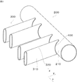
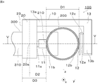
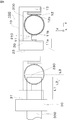
- the figure which shows the fixing jig which concerns on embodiment of this disclosure The figure which shows the refrigerant distributor and the flat refrigerant pipe which concerns on embodiment of this disclosure.
- a flowchart showing a method of manufacturing a heat exchanger according to an embodiment of the present disclosure Sectional drawing which shows the heat exchanger manufactured by the method of manufacturing the heat exchanger of embodiment of this disclosure. Sectional drawing which shows the heat exchanger manufactured by the method of manufacturing the heat exchanger of the comparative example. Sectional drawing which shows the heat exchanger manufactured by the method of manufacturing the heat exchanger of the comparative example.
- Rear view showing the fixing jig according to the modified example The figure which shows the method of removing a flat refrigerant pipe from a fixing jig which concerns on a modification.
- Rear view showing the fixing jig according to the modified example The figure which shows the method of removing a flat refrigerant pipe from a fixing jig which concerns on a modification.
- Side sectional view showing a fixing jig according to a modified example Cross-sectional view of XVIII-XVIII in FIG.
- Rear view showing the fixing jig according to the modified example Rear view showing the fixing jig according to the modified example
- the fixing jig 100 is used when joining a plurality of flat refrigerant pipes 300 to the refrigerant distributor 200, and is a first unit for fixing the refrigerant distributor 200.
- a fixing portion 10 and a second fixing portion 20 for fixing a plurality of flat refrigerant pipes 300 are provided.
- a heat exchanger created by joining a plurality of flat refrigerant pipes 300 to a refrigerant distributor 200 causes a refrigerant to flow from the refrigerant distributor 200 to the flat refrigerant pipe 300 and exchanges heat with air flowing between the flat refrigerant pipes 300. It is used in the indoor unit or outdoor unit of an air conditioner that regulates the temperature of the air.
- the direction in which the refrigerant distributor 200 extends is set as the x direction
- the direction in which the flat refrigerant pipe 300 extends is set as the y direction
- the direction perpendicular to the x direction and the y direction is set as the z direction.
- the refrigerant distributor 200 is a pipe having a cylindrical shape for supplying a refrigerant to the flat refrigerant pipe 300, and has a plurality of holes 220 on the side surface 210 to which the flat refrigerant pipe 300 is attached.
- the refrigerant distributor 200 is an example of a main pipe.
- the refrigerant distributor 200 is made of aluminum or an aluminum alloy in order to increase the thermal conductivity.
- the flat refrigerant pipe 300 is joined to the refrigerant distributor 200 by a brazing material 400, and has a pair of flat plate portions 310 extending in the longitudinal direction and a pair of curved portions 320 curved in the circumferential direction. It is a flat tube having flat plate portions 310 and curved portions 320 alternately arranged in the circumferential direction.
- the flat refrigerant pipe 300 is an example of an auxiliary pipe.
- the brazing filler metal 400 is supplied to the joint portion between the flat refrigerant pipe 300 and the refrigerant distributor 200 by the brazing filler metal supply nozzle 410 shown in FIG.
- connection portion between the refrigerant distributor 200 and the flat refrigerant pipe 300 needs to be sufficiently expanded with the brazing filler metal 400 covering the entire connection portion. By filling all the connecting portions with the wax material 400, it functions as a flow path through which the refrigerant flows.
- the pair of flat plate portions 310 are arranged in parallel with each other.
- the extending direction of the flat refrigerant pipe 300 is arranged perpendicular to the extending direction of the refrigerant distributor 200.
- the flat refrigerant pipe 300 is made of aluminum or an aluminum alloy like the refrigerant distributor 200.
- the first fixing portion 10 has an insertion amount adjusting pin 11 for adjusting the insertion amount of the flat refrigerant pipe 300, and a first fixing portion 10 for pressing the refrigerant distributor 200 against the insertion amount adjusting pin 11. It has a pressing portion 12 and an arm 13 for fixing the first pressing portion 12.
- the insertion amount adjusting pin 11 has a screw 11a attached to the second fixing portion 20 and a contact surface 11b that abuts on the side surface 210 of the refrigerant distributor 200, and adjusts the length protruding in the y direction. Then, the amount of the flat refrigerant pipe 300 inserted into the refrigerant distributor 200 is adjusted.
- the first pressing portion 12 includes a fixing portion 12a attached to the arm 13, a contact portion 12b that abuts on the side surface 210 of the refrigerant distributor 200, and a curved portion 12c that connects the fixing portion 12a and the contact portion 12b. It is a spring that holds the refrigerant distributor 200 in the ⁇ y direction by bending the curved portion 12c.
- the first pressing portion 12 is arranged so as to face the insertion amount adjusting pin 11, and presses the refrigerant distributor 200 against the insertion amount adjusting pin 11 to fix the refrigerant distributor 200. Since the first pressing portion 12 needs to withstand the temperature of brazing in the furnace, it is preferable to use a spring having high heat resistance using carbon.
- the arm 13 has one end 13a connected to the second fixing portion 20 and the other end 13b for fixing the first pressing portion 12.
- the second fixing portion 20 fixes the vicinity of the insertion portion of the plurality of flat refrigerant pipes 300, allows the plurality of flat refrigerant pipes 300 to be extended by thermal expansion, and has a plurality of flat refrigerants with respect to the refrigerant distributor 200.
- a plurality of flat refrigerant pipes 300 are fixed at positions where the deviation of the insertion amount of the pipe 300 during brazing can be suppressed.
- the second fixing portion 20 preferably fixes the flat refrigerant pipe 300 at a position smaller than the outer diameter D1 of the refrigerant distributor 200 from the side surface 210 of the refrigerant distributor 200.
- the distance D2 from the side surface 210 of the refrigerant distributor 200 to the center 20a of the second fixing portion 20 in the y direction is smaller than the outer diameter D1 of the refrigerant distributor 200 in the y direction.
- the distance D3 from the side surface 210 of the refrigerant distributor 200 to the reference surface 23 described later is smaller than the outer diameter D1 of the refrigerant distributor 200 in the y direction.
- the second fixing portion 20 has an E-shape when viewed in the y direction, and has a plurality of recesses 21 in which the flat refrigerant pipe 300 is arranged, and the flat refrigerant pipe 300. It has a plurality of second pressing portions 22 for pressing and fixing, and a reference surface 23 for determining the position of the flat refrigerant pipe 300 in the y direction.
- the recess 21 has a contact surface 21a that abuts on the flat plate portion 310 of the flat refrigerant pipe 300, and a mounting surface 21b to which the second pressing portion 22 is attached.
- the contact surface 21a and the mounting surface 21b are arranged so as to face each other and parallel to each other.
- the second pressing portion 22 is a curved portion that connects the fixed portion 22a attached to the mounting surface 21b, the abutting portion 22b that abuts on the flat plate portion 310 of the flat refrigerant pipe 300, and the fixing portion 22a and the abutting portion 22b. It is a spring having a portion 22c and pressing the flat refrigerant pipe 300 in the x-direction or ⁇ x-direction by bending the curved portion 22c.
- the second pressing portion 22 fixes the flat refrigerant pipe 300 to the second fixing portion 20 by pressing the flat refrigerant pipe 300 against the contact surface 21a.
- the second pressing portion 22 needs to withstand the temperature of brazing in the furnace like the first pressing portion 12 described above, it is preferable to use a spring having high heat resistance using carbon. .. Since the second fixing portion 20 is integrated with the first fixing portion 10, the flat refrigerant pipe 300 and the refrigerant distributor 200 can be fixedly held via the fixing jig 100.
- the reference surface 23 has a plane perpendicular to the y direction as a reference for determining the amount of the flat refrigerant pipe 300 to be inserted into the refrigerant distributor 200.
- the tip portion 330 of the flat refrigerant pipe 300 is arranged at a position separated from the reference surface 23 by a reference length L1 in the y direction. It is preferable that the tip 330 of the flat refrigerant pipe 300 is inserted with a minimum insertion amount L2 or more so that the flow path is not blocked by the brazing material 400. Further, in order to facilitate the flow of the refrigerant, it is necessary to secure a sufficient area of the refrigerant flowing portion.
- the maximum insertion amount L3 of the tip portion 330 of the flat refrigerant pipe 300 is small. Therefore, the maximum insertion amount L3 is determined to be as small as possible based on the error that occurs during manufacturing.
- the reference length L1 is set to a length in which the tip 330 of the flat refrigerant pipe 300 is inserted into the refrigerant distributor 200 with a minimum insertion amount L2 or more and a maximum insertion amount L3 or less.
- the minimum insertion amount L2 3 mm so that the flow path is not blocked by the brazing filler metal 400. ..
- the insertion amount L2 3 mm
- the area of the refrigerant flow portion is 70% with respect to the inner diameter cross-sectional area of the refrigerant distributor 200.
- the maximum insertion amount L3 of the flat refrigerant pipe 300 is 6.3 mm or less.
- the insertion amount L4 is the average of the minimum insertion amount L2 and the maximum insertion amount L3.
- the reference length L1 may be from the position of the tip portion 330 into which the tip portion 330 of the flat refrigerant pipe 300 is inserted with the insertion amount L4 to the reference surface 23.
- a temporary fixing jig 30 for temporarily fixing the flat refrigerant pipe 300 shown in FIG. 8 is used. It is good.
- the fixing jig 100 and the temporary fixing jig 30 form a jig set.
- the temporary fixing jig 30 has the same structure as the second fixing portion 20, so that the flat refrigerant pipe 300 is temporarily fixed.
- the temporary fixing jig 30 has a reference surface 31 having a plane perpendicular to the direction in which the flat refrigerant pipe 300 to be attached extends.
- the tip portion 330 of the flat refrigerant pipe 300 is arranged at a position of the reference length L1 from the reference surface 31, and the flat refrigerant pipe 300 is temporarily fixed.
- the reference surface 23 of the fixing jig 100 to which the refrigerant distributor 200 is attached in advance is arranged so as to face the reference surface 31 of the temporary fixing jig 30 to which the flat refrigerant pipe 300 is temporarily fixed.
- the fixing jig 100 is moved in the ⁇ y direction, and the reference surface 23 of the fixing jig 100 is brought closer to the reference surface 31 of the temporary fixing jig 30.
- the temporary fixing jig 30 is removed from the flat refrigerant pipe 300.
- the refrigerant distributor 200 and the flat refrigerant pipe 300 are attached to the fixing jig 100.
- the tip portion 330 of the flat refrigerant pipe 300 is arranged at a position of the reference length L1 from the reference surface 23.
- the method for manufacturing the heat exchanger is a distributor attaching step (step S101) of attaching the refrigerant distributor 200 to the fixing jig 100, and temporarily fixing the flat refrigerant pipe 300.
- a flat tube temporary fixing step step S102
- a flat tube attaching step of attaching the flat refrigerant pipe 300 to the fixing jig 100 step S103
- a joining step of joining a plurality of flat refrigerant pipes 300 to the refrigerant distributor 200 step.
- S104 and a jig removal step (step S105) for removing the fixing jig 100.
- the refrigerant distributor 200 Before starting the production of the heat exchanger, prepare the refrigerant distributor 200 and the flat refrigerant pipe 300.
- the refrigerant distributor 200 has a plurality of holes 220 to which the flat refrigerant pipe 300 is attached to the side surface 210.
- the refrigerant distributor 200 is made of aluminum or an aluminum alloy in order to increase the thermal conductivity.
- the flat refrigerant pipe 300 has a pair of flat plate portions 310 extending in the longitudinal direction and a pair of curved portions 320 curved in the circumferential direction, and the flat plate portions 310 and the curved portions 320 are alternately arranged in the circumferential direction. There is.
- the pair of flat plate portions 310 are arranged in parallel with each other.
- the flat refrigerant pipe 300 is made of aluminum or an aluminum alloy like the refrigerant distributor 200.
- the refrigerant distributor 200 is mounted between the contact surface 11b of the insertion amount adjusting pin 11 and the contact portion 12b of the first pressing portion 12.
- the distributor mounting step (step S101) is an example of the main piping mounting step.
- the flat refrigerant pipe 300 is temporarily fixed to the temporary fixing jig 30 shown in FIG.
- the flat pipe temporary fixing step (step S102) is an example of the auxiliary pipe temporary fixing step.
- the temporary fixing jig 30 temporarily fixes the flat refrigerant pipe 300, and has a reference surface 31.
- the reference plane 31 has a plane perpendicular to the extending direction of the flat refrigerant pipe 300 to be attached.
- the tip portion 330 of the flat refrigerant pipe 300 is arranged at a position of the reference length L1 from the reference surface 31 and temporarily fixed.
- the reference length L1 is set to the length at which the tip portion 330 of the flat refrigerant pipe 300 is inserted into the refrigerant distributor 200 with a minimum insertion amount L2 or more and a maximum insertion amount L3 or less.
- the minimum insertion amount L2 is an insertion amount in which the flow path is not blocked by the brazing filler metal 400.
- the maximum insertion amount L3 is preferably small in order to increase the area of the refrigerant flow portion as much as possible.
- the flat refrigerant pipe 300 temporarily fixed to the temporary fixing jig 30 is attached to the fixing jig 100 to which the refrigerant distributor 200 is attached.
- the flat pipe mounting step (step S103) is an example of the sub pipe mounting step. First, the reference surface 23 of the fixing jig 100 to which the refrigerant distributor 200 is attached is arranged so as to face the reference surface 31 of the temporary fixing jig 30 to which the flat refrigerant pipe 300 is temporarily fixed. Next, the fixing jig 100 is moved in the ⁇ y direction, and the reference surface 23 of the fixing jig 100 is brought closer to the reference surface 31 of the temporary fixing jig 30.
- the temporary fixing jig 30 is removed from the flat refrigerant pipe 300.
- the refrigerant distributor 200 and the flat refrigerant pipe 300 are attached to the fixing jig 100.
- the tip portion 330 of the flat refrigerant pipe 300 is arranged at a position of the reference length L1 from the reference surface 23.
- the insertion amount of the flat refrigerant pipe 300 with respect to the refrigerant distributor 200 is adjusted by the insertion amount adjusting pin 11.
- the brazing material 400 is arranged by the brazing material supply nozzle 410 shown in FIG. 1 at the joint portion between the refrigerant distributor 200 and the flat refrigerant pipe 300, and brazing is executed.
- the fixing jig 100, the refrigerant distributor 200, and the flat refrigerant pipe 300 are fired. Place it inside and heat it in a furnace to braze.
- the refrigerant distributor 200 and the flat refrigerant pipe 300 are fixed by the fixing jig 100, they are brazed while holding the insertion amount, so that the flat refrigerant pipe 300 and the refrigerant distributor 200 are joined at appropriate positions. To.
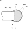
- the fixing jig 100 is removed from the refrigerant distributor 200 and the flat refrigerant pipe 300 joined in the joining step (step S104). Since the refrigerant distributor 200 is pressed and held by the first pressing portion 12 and the flat refrigerant pipe 300 is pressed and held by the second pressing portion 22, the fixing jig 100 is pressed and held in the x direction. It can be removed by moving it. As a result, as shown in FIG. 10, a heat exchanger in which the flat refrigerant pipe 300 is joined to the refrigerant distributor 200 is manufactured.
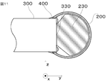
- the brazing filler metal 400 covers the entire connecting portion and is sufficiently widened, and all the grooves of the connecting portion are filled with the brazing filler metal 400, so that the refrigerant flow portion 230 is secured inside the refrigerant distributor 200, and the refrigerant flows as a flow path. Function.
- the refrigerant distributor 200 and the flat refrigerant pipe 300 are brazed while being fixed by the fixing jig 100.
- the flat refrigerant pipe 300 and the refrigerant distributor 200 are joined at appropriate positions. Further, by fixing the vicinity of the insertion points of the plurality of flat refrigerant pipes 300, the flat refrigerant pipe 300 can be extended due to thermal expansion, and the amount of the flat refrigerant pipe 300 inserted into the refrigerant distributor 200 is deviated during brazing. It can be suppressed.
- the fixing jig 100 has a reference surface 23, and by arranging the tip portion 330 of the flat refrigerant pipe 300 at a position of the reference length L1 from the reference surface 23, the flat refrigerant pipe 300 is attached to the refrigerant distributor 200. It can be inserted with an appropriate insertion amount.
- the fixing jig 100 has the insertion amount adjusting pin 11, when the tip portion 330 of the flat refrigerant pipe 300 is displaced and arranged in the flat tube mounting step (step S103), the insertion amount adjusting pin 11 is used.
- the amount of the flat refrigerant pipe 300 inserted into the refrigerant distributor 200 can be adjusted.
- the distributor mounting step step S101).
- the flat pipe mounting step step S103
- the refrigerant distributor 200 and the flat refrigerant pipe 300 fixed by the fixing jig 100 are conveyed, the misalignment can be prevented.
- the refrigerant distributor 200 and the flat refrigerant pipe 300 are fixed by the fixing jig 100, it is possible to suppress the occurrence of misalignment due to thermal expansion when brazing is performed in the furnace.
- the brazing filler metal 400 may flow into the inside of the flat refrigerant pipe 300 from the tip portion 330, and the flow path of the flat refrigerant pipe 300 may be blocked or the flow path may be narrow. There is a risk of becoming. If the flow path of the flat refrigerant pipe 300 is blocked, the distribution performance may deteriorate, which may lead to a deterioration in the performance of the heat exchanger. Further, when the insertion amount of the flat refrigerant pipe 300 into the refrigerant distributor 200 is large, as shown in FIG.
- the method of maintaining the positional relationship between the flat refrigerant pipe and the refrigerant distributor by devising the shape of the parts in this way is that the tip of the flat refrigerant pipe becomes narrower and the flow path may become narrower, and a hit stop is provided. There is a risk that the flow path will be blocked, and there is a drawback that the performance will deteriorate.
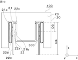
- the second pressing portion 22 may further include a member for releasing the pressing force, and as shown in FIG. 13, a pair of levers 22d extending from the contact portion 22b to remove the flat refrigerant pipe 300 are connected to the second pressing portion 22. You may. When removing the fixing jig 100, as shown in FIG. 14, by tightening the tips of the pair of levers 22d, the contact portion 22b can be separated from the flat refrigerant pipe 300, and the flat refrigerant pipe 300 can be easily removed. It will be possible.
- the distance D4 from the curved portion 22c to the tip of the lever 22d is made longer than the distance D3 from the curved portion 22c serving as the fulcrum to the abutting portion 22b in contact with the flat refrigerant pipe 300, a smaller force is applied by the principle of the lever. It is possible to operate the lever 22d with. Further, since the lever 22d is provided, the flat refrigerant pipe 300 can be removed without applying a pressing force from the second pressing portion 22 to the flat refrigerant pipe 300 at the time of removal after joining, and the flat refrigerant pipe 300 can be removed. The risk of scratching is reduced.
- the pressing force is higher in consideration of the deviation due to transportation from the distributor mounting step (step S101) to the joining step (step S104). Even if the pressing portion 22 of the above presses the flat refrigerant pipe 300 with a large force, the presence of the lever 22d can reduce the force required for removal.
- the second pressing portion 22 arranged in the second fixing portion 20 presses the pair of levers 22e by the pusher 24 in order to facilitate the removal of the flat refrigerant pipe 300.
- the pressing force may be released.
- the pusher 24 is arranged in the groove portion 25 provided in the second fixing portion 20, is restrained by the pusher fixing pin 26 in the groove portion 25, and slides in the z direction.
- a lever 22e is connected to the contact portion 22b of the second pressing portion 22.
- the pusher 24 includes a hole 24a through which the pusher fixing pin 26 penetrates, and an inclined portion 24b that comes into contact with the lever 22e. As shown in FIG.
- the second fixing portion 20 has a pair of contact surfaces 27 arranged facing each other and a pair of contact surfaces 27, as shown in FIGS. 17 and 18, instead of the second pressing portion 22.
- a cam 28 may be provided between the two, and the contact surface 27 may be provided with a cam 28 that presses and fixes the flat refrigerant pipe 300.
- the cam 28 has an elliptical shape when viewed in the x direction, and is rotated about a rotation axis AX extending in the z direction by the cam turning knob 29.
- the rotation shaft AX is arranged between the pair of contact surfaces 27.
- the first pressing portion 12 provided on the first fixing portion 10 of the fixing jig 100 presses the refrigerant distributor 200 against the insertion amount adjusting pin 11 to fix the refrigerant distributor 200.
- the first fixing portion 10 may have a fixing screw 14 for fixing the refrigerant distributor 200 in place of the first pressing portion 12 as long as the refrigerant distributor 200 can be fixed.
- a screw turning knob 15 for turning the fixing screw 14 is attached to the fixing screw 14. By turning the screwdriver knob 15, the refrigerant distributor 200 is pressed against the insertion amount adjusting pin 11 to fix the positional relationship between the refrigerant distributor 200 and the first fixing portion 10.
- the fixing screw 14 can be loosened by turning the screw turning knob 15, and the refrigerant distributor 200 can be easily removed.
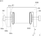
- the second fixing portion 20 has a contact surface 21c provided so as to be sandwiched between the pair of flat refrigerant pipes 300, as shown in FIG. 19, instead of the second pressing portion 22 or the cam 28.
- a fixing screw 32 provided toward the contact surface 21c and pressing and fixing the flat refrigerant pipe 300 may be provided on the contact surface 21c.
- the fixing screw 32 has a screw turning knob 32a, a screw portion 32b whose one end is attached to the screw turning knob 32a, and a holding plate 32c whose one end is attached to the other end of the screw portion 32b.
- the fixing screw 32 rotates the screw turning knob 32a and moves the holding plate 32c toward the contact surface 21c by the screw mechanism of the screw portion 32b, so that the holding plate 32c is pressed against the flat refrigerant pipe 300. It can be fixed by friction. Further, by turning the screw turning knob 32a at the time of removal, the holding plate 32c can be easily removed by separating from the flat refrigerant pipe 300.
- the second fixing portion 20 may be a combination of the second pressing portion 22'and the fixing screw 32.
- the second pressing portion 22' has the same configuration as the above-mentioned second pressing portion 22.
- the second pressing portion 22' is attached to the pressing plate 32c.
- the screw turning knob 32a By rotating the screw turning knob 32a and moving it toward the contact surface 21c by the screw mechanism of the screw portion 32b, the second pressing portion 22'is pressed against the flat refrigerant pipe 300 and fixed by friction. Can be done. Further, by turning the screw turning knob 32a at the time of removal, the second pressing portion 22'is separated from the flat refrigerant pipe 300 and can be easily removed.
- the second pressing portion 22' By providing the second pressing portion 22'at the portion pressed against the flat refrigerant pipe 300, even if the screw portion 32b linearly expands due to the heat of brazing during fixing, it is absorbed by the elasticity of the curved portion 22c', so that it is flat. The refrigerant pipe 300 is not damaged. Further, in FIG. 20, the second pressing portion 22'is attached to the pressing plate 32c, but the second pressing portion 22'may be attached to the contact surface 21c. In this case, the holding plate 32c can be fixed by friction by pressing the flat refrigerant pipe 300 against the second pressing portion 22'.
- the joint portion between the refrigerant distributor 200 and the flat refrigerant pipe 300 is joined by the brazing filler metal 400 has been described.
- the refrigerant distributor 200 and the flat refrigerant pipe 300 may be joined to form a flow path through which the refrigerant flows, and may be connected by welding or may be joined by another method.
- the heat exchanger is used as an indoor unit or an outdoor unit of an air conditioner that regulates the temperature of air by exchanging heat with the air flowing between the flat refrigerant pipes 300 .
- the heat exchanger exchanges heat with the fluid flowing between the flat refrigerant pipes 300, and its use is not limited.
- the heat exchanger may be used in a refrigerator or freezer. Further, the heat exchanger may be used as a radiator for cooling the cooling water by exchanging heat between the cooling water flowing inside the flat refrigerant pipe 300 and the air flowing between the flat refrigerant pipes 300.
- the fluid flowing inside the refrigerant distributor 200 and the flat refrigerant pipe 300 may be a liquid or a gas. Further, the fluid flowing between the flat refrigerant pipes 300 may be a liquid or a gas.
- the refrigerant distributor 200 and the flat refrigerant pipe 300 are made of aluminum or an aluminum alloy.
- the refrigerant distributor 200 and the flat refrigerant pipe 300 may be made of any metal used for the heat exchanger, and may be made of copper or a copper alloy. Further, the refrigerant distributor 200 and the flat refrigerant pipe 300 may be provided with a protective film including a metal film or a resin film on the surface thereof.
- the fixing jig 100 fixes the refrigerant distributor 200 having a cylindrical shape as the main pipe and the flat refrigerant pipe 300 as the sub pipe. It suffices if the fixing jig 100, the main pipe having a plurality of holes on the side surface, and the plurality of sub pipes inserted into the holes provided on the side surface of the main pipe can be fixed.
- the cross-sectional shape of the main pipe is not particularly limited and may be an ellipse, a semicircle or a polygon.
- the cross-sectional shape of the sub-pipe is not particularly limited, and may be a circle, an ellipse, a semicircle, or a polygon.
Landscapes
- Engineering & Computer Science (AREA)
- Mechanical Engineering (AREA)
- Physics & Mathematics (AREA)
- Thermal Sciences (AREA)
- General Engineering & Computer Science (AREA)
- Heat-Exchange Devices With Radiators And Conduit Assemblies (AREA)
Priority Applications (2)
| Application Number | Priority Date | Filing Date | Title |
|---|---|---|---|
| JP2022530099A JP7353490B2 (ja) | 2020-06-08 | 2021-05-21 | 固定治具および熱交換器の製造方法 |
| CN202180031612.5A CN115605309A (zh) | 2020-06-08 | 2021-05-21 | 固定辅具以及热交换器的制造方法 |
Applications Claiming Priority (2)
| Application Number | Priority Date | Filing Date | Title |
|---|---|---|---|
| JP2020-099133 | 2020-06-08 | ||
| JP2020099133 | 2020-06-08 |
Publications (1)
| Publication Number | Publication Date |
|---|---|
| WO2021251104A1 true WO2021251104A1 (ja) | 2021-12-16 |
Family
ID=78845989
Family Applications (1)
| Application Number | Title | Priority Date | Filing Date |
|---|---|---|---|
| PCT/JP2021/019364 Ceased WO2021251104A1 (ja) | 2020-06-08 | 2021-05-21 | 固定治具および熱交換器の製造方法 |
Country Status (3)
| Country | Link |
|---|---|
| JP (1) | JP7353490B2 (https=) |
| CN (1) | CN115605309A (https=) |
| WO (1) | WO2021251104A1 (https=) |
Cited By (1)
| Publication number | Priority date | Publication date | Assignee | Title |
|---|---|---|---|---|
| KR102519340B1 (ko) * | 2022-06-24 | 2023-04-06 | (주)비제이 테크 | 챔버형 용접헤드용 티(t)형 배관 고정용 지그장치 |
Citations (2)
| Publication number | Priority date | Publication date | Assignee | Title |
|---|---|---|---|---|
| JPS4977494U (https=) * | 1972-10-23 | 1974-07-04 | ||
| JP2004301499A (ja) * | 2003-03-18 | 2004-10-28 | Showa Denko Kk | 熱交換器の仮組み用管素材矯正部材、熱交換器の仮組み装置および仮組み方法 |
Family Cites Families (15)
| Publication number | Priority date | Publication date | Assignee | Title |
|---|---|---|---|---|
| JPS62275570A (ja) * | 1986-05-22 | 1987-11-30 | Showa Alum Corp | 熱交換器の製造方法 |
| JP2925362B2 (ja) * | 1991-07-08 | 1999-07-28 | 昭和アルミニウム株式会社 | 熱交換器スケルトンの組立て方法 |
| JPH08233484A (ja) * | 1995-02-28 | 1996-09-13 | Showa Alum Corp | 金属製熱交換器 |
| JP2602085Y2 (ja) * | 1996-03-28 | 1999-12-20 | 株式会社ゼクセル | 熱交換器のブラケット |
| CN100439850C (zh) * | 2003-03-18 | 2008-12-03 | 昭和电工株式会社 | 用于临时组装热交换器的管坯校正件,以及用于临时组装热交换器的装置和方法 |
| CN102886666B (zh) * | 2011-07-22 | 2015-01-14 | 常州市西屋自动化有限公司 | 换热器的管翅定位工装及装配方法 |
| CN102886585B (zh) * | 2011-07-22 | 2015-03-25 | 常州市西屋自动化有限公司 | 换热器的管束定位工装及装配方法 |
| JP2014040964A (ja) * | 2012-08-22 | 2014-03-06 | Daikin Ind Ltd | 冷媒熱交換器及びその製造方法 |
| JP2014052147A (ja) | 2012-09-07 | 2014-03-20 | Daikin Ind Ltd | 熱交換器及びその製造方法 |
| CN203992938U (zh) * | 2014-08-11 | 2014-12-10 | 杭州钱联散热器有限公司 | 片式散热器焊接工装 |
| CN206356823U (zh) * | 2016-12-16 | 2017-07-28 | 广东美的暖通设备有限公司 | 用于笛形管的焊接工装 |
| CN206415825U (zh) * | 2016-12-23 | 2017-08-18 | 天津五洲同创空调制冷设备有限公司 | 集管焊接工装 |
| CN108620792A (zh) * | 2018-05-04 | 2018-10-09 | 南方风机股份有限公司 | 一种核电站换热器汇集管焊接工装 |
| CN108673020A (zh) * | 2018-06-19 | 2018-10-19 | 广东海悟科技有限公司 | 一种空调集气管焊接工装 |
| CN210209267U (zh) * | 2019-07-15 | 2020-03-31 | 广东海悟科技有限公司 | 一种可调式管路焊接工装 |
-
2021
- 2021-05-21 JP JP2022530099A patent/JP7353490B2/ja active Active
- 2021-05-21 WO PCT/JP2021/019364 patent/WO2021251104A1/ja not_active Ceased
- 2021-05-21 CN CN202180031612.5A patent/CN115605309A/zh active Pending
Patent Citations (2)
| Publication number | Priority date | Publication date | Assignee | Title |
|---|---|---|---|---|
| JPS4977494U (https=) * | 1972-10-23 | 1974-07-04 | ||
| JP2004301499A (ja) * | 2003-03-18 | 2004-10-28 | Showa Denko Kk | 熱交換器の仮組み用管素材矯正部材、熱交換器の仮組み装置および仮組み方法 |
Cited By (2)
| Publication number | Priority date | Publication date | Assignee | Title |
|---|---|---|---|---|
| KR102519340B1 (ko) * | 2022-06-24 | 2023-04-06 | (주)비제이 테크 | 챔버형 용접헤드용 티(t)형 배관 고정용 지그장치 |
| WO2023249170A1 (ko) * | 2022-06-24 | 2023-12-28 | (주)비제이 테크 | 챔버형 용접헤드용 티(t)형 배관 고정용 지그장치 |
Also Published As
| Publication number | Publication date |
|---|---|
| CN115605309A (zh) | 2023-01-13 |
| JPWO2021251104A1 (https=) | 2021-12-16 |
| JP7353490B2 (ja) | 2023-09-29 |
Similar Documents
| Publication | Publication Date | Title |
|---|---|---|
| JP5279514B2 (ja) | 熱交換器、その製造方法及びこの熱交換器を備えた空気調和機 | |
| US10066878B2 (en) | Heat exchanger integrated assembly and manufacturing method thereof | |
| US20110094257A1 (en) | Micro-channel heat exchanger suitable for bending | |
| JP2017075741A (ja) | 熱交換器 | |
| KR20010043366A (ko) | 납땜 성능이 개선된 열교환기 매니폴드 블록 | |
| CN106482568B (zh) | 用于换热器的换热管、换热器及其装配方法 | |
| WO2021251104A1 (ja) | 固定治具および熱交換器の製造方法 | |
| JP5171915B2 (ja) | 冷却管構造 | |
| JP5544412B2 (ja) | 冷却管構造 | |
| JP4169407B2 (ja) | 取付ブラケット付熱交換器 | |
| WO2022242550A1 (zh) | 管夹组件以及具有该管夹组件的换热器 | |
| JP2017198403A (ja) | 扁平管熱交換器およびその製造方法 | |
| WO2024194523A1 (en) | Cooling element | |
| US20180195815A1 (en) | Heat exchanger header tank | |
| JP2004353954A (ja) | 熱交換器 | |
| CN119146786A (zh) | 一种空间长距离热管排布组件及排布方法 | |
| JP7117839B2 (ja) | 熱交換器用ヘッダ及び熱交換器 | |
| KR20110083953A (ko) | 열교환기용 헤더 파이프 연결구 | |
| JPWO2021251104A5 (https=) | ||
| JP2018179332A (ja) | 仮固定構造およびそれを備える熱交換器、並びに仮固定方法 | |
| JP2008261550A (ja) | 熱交換器およびその製造方法 | |
| EP4039402B1 (en) | A method of bonding a capillary tube and a suction pipe by means of a fiber laser welding head and corresponding apparatus | |
| KR101023959B1 (ko) | 열교환기의 파이프 고정구조 | |
| KR100256405B1 (ko) | 공기조화기용 열교환기의 제조방법 | |
| JP2018146223A (ja) | 熱交換器 |
Legal Events
| Date | Code | Title | Description |
|---|---|---|---|
| 121 | Ep: the epo has been informed by wipo that ep was designated in this application |
Ref document number: 21820859 Country of ref document: EP Kind code of ref document: A1 |
|
| ENP | Entry into the national phase |
Ref document number: 2022530099 Country of ref document: JP Kind code of ref document: A |
|
| NENP | Non-entry into the national phase |
Ref country code: DE |
|
| 122 | Ep: pct application non-entry in european phase |
Ref document number: 21820859 Country of ref document: EP Kind code of ref document: A1 |