WO2021245795A1 - 冷凍サイクル装置 - Google Patents
冷凍サイクル装置 Download PDFInfo
- Publication number
- WO2021245795A1 WO2021245795A1 PCT/JP2020/021799 JP2020021799W WO2021245795A1 WO 2021245795 A1 WO2021245795 A1 WO 2021245795A1 JP 2020021799 W JP2020021799 W JP 2020021799W WO 2021245795 A1 WO2021245795 A1 WO 2021245795A1
- Authority
- WO
- WIPO (PCT)
- Prior art keywords
- refrigerant
- heat exchanger
- passage
- hot gas
- liquid
- Prior art date
- Legal status (The legal status is an assumption and is not a legal conclusion. Google has not performed a legal analysis and makes no representation as to the accuracy of the status listed.)
- Ceased
Links
Images



Classifications
-
- F—MECHANICAL ENGINEERING; LIGHTING; HEATING; WEAPONS; BLASTING
- F25—REFRIGERATION OR COOLING; COMBINED HEATING AND REFRIGERATION SYSTEMS; HEAT PUMP SYSTEMS; MANUFACTURE OR STORAGE OF ICE; LIQUEFACTION SOLIDIFICATION OF GASES
- F25B—REFRIGERATION MACHINES, PLANTS OR SYSTEMS; COMBINED HEATING AND REFRIGERATION SYSTEMS; HEAT PUMP SYSTEMS
- F25B13/00—Compression machines, plants or systems, with reversible cycle
-
- F—MECHANICAL ENGINEERING; LIGHTING; HEATING; WEAPONS; BLASTING
- F25—REFRIGERATION OR COOLING; COMBINED HEATING AND REFRIGERATION SYSTEMS; HEAT PUMP SYSTEMS; MANUFACTURE OR STORAGE OF ICE; LIQUEFACTION SOLIDIFICATION OF GASES
- F25B—REFRIGERATION MACHINES, PLANTS OR SYSTEMS; COMBINED HEATING AND REFRIGERATION SYSTEMS; HEAT PUMP SYSTEMS
- F25B47/00—Arrangements for preventing or removing deposits or corrosion, not provided for in another subclass
- F25B47/02—Defrosting cycles
- F25B47/022—Defrosting cycles hot gas defrosting
-
- F—MECHANICAL ENGINEERING; LIGHTING; HEATING; WEAPONS; BLASTING
- F25—REFRIGERATION OR COOLING; COMBINED HEATING AND REFRIGERATION SYSTEMS; HEAT PUMP SYSTEMS; MANUFACTURE OR STORAGE OF ICE; LIQUEFACTION SOLIDIFICATION OF GASES
- F25B—REFRIGERATION MACHINES, PLANTS OR SYSTEMS; COMBINED HEATING AND REFRIGERATION SYSTEMS; HEAT PUMP SYSTEMS
- F25B40/00—Subcoolers, desuperheaters or superheaters
-
- F—MECHANICAL ENGINEERING; LIGHTING; HEATING; WEAPONS; BLASTING
- F25—REFRIGERATION OR COOLING; COMBINED HEATING AND REFRIGERATION SYSTEMS; HEAT PUMP SYSTEMS; MANUFACTURE OR STORAGE OF ICE; LIQUEFACTION SOLIDIFICATION OF GASES
- F25B—REFRIGERATION MACHINES, PLANTS OR SYSTEMS; COMBINED HEATING AND REFRIGERATION SYSTEMS; HEAT PUMP SYSTEMS
- F25B41/00—Fluid-circulation arrangements
- F25B41/30—Expansion means; Dispositions thereof
- F25B41/31—Expansion valves
-
- F—MECHANICAL ENGINEERING; LIGHTING; HEATING; WEAPONS; BLASTING
- F25—REFRIGERATION OR COOLING; COMBINED HEATING AND REFRIGERATION SYSTEMS; HEAT PUMP SYSTEMS; MANUFACTURE OR STORAGE OF ICE; LIQUEFACTION SOLIDIFICATION OF GASES
- F25B—REFRIGERATION MACHINES, PLANTS OR SYSTEMS; COMBINED HEATING AND REFRIGERATION SYSTEMS; HEAT PUMP SYSTEMS
- F25B49/00—Arrangement or mounting of control or safety devices
- F25B49/02—Arrangement or mounting of control or safety devices for compression type machines, plants or systems
-
- F—MECHANICAL ENGINEERING; LIGHTING; HEATING; WEAPONS; BLASTING
- F25—REFRIGERATION OR COOLING; COMBINED HEATING AND REFRIGERATION SYSTEMS; HEAT PUMP SYSTEMS; MANUFACTURE OR STORAGE OF ICE; LIQUEFACTION SOLIDIFICATION OF GASES
- F25B—REFRIGERATION MACHINES, PLANTS OR SYSTEMS; COMBINED HEATING AND REFRIGERATION SYSTEMS; HEAT PUMP SYSTEMS
- F25B2313/00—Compression machines, plants or systems with reversible cycle not otherwise provided for
- F25B2313/003—Indoor unit with water as a heat sink or heat source
-
- F—MECHANICAL ENGINEERING; LIGHTING; HEATING; WEAPONS; BLASTING
- F25—REFRIGERATION OR COOLING; COMBINED HEATING AND REFRIGERATION SYSTEMS; HEAT PUMP SYSTEMS; MANUFACTURE OR STORAGE OF ICE; LIQUEFACTION SOLIDIFICATION OF GASES
- F25B—REFRIGERATION MACHINES, PLANTS OR SYSTEMS; COMBINED HEATING AND REFRIGERATION SYSTEMS; HEAT PUMP SYSTEMS
- F25B2313/00—Compression machines, plants or systems with reversible cycle not otherwise provided for
- F25B2313/025—Compression machines, plants or systems with reversible cycle not otherwise provided for using multiple outdoor units
- F25B2313/0252—Compression machines, plants or systems with reversible cycle not otherwise provided for using multiple outdoor units with bypasses
- F25B2313/02522—Compression machines, plants or systems with reversible cycle not otherwise provided for using multiple outdoor units with bypasses during defrosting
-
- F—MECHANICAL ENGINEERING; LIGHTING; HEATING; WEAPONS; BLASTING
- F25—REFRIGERATION OR COOLING; COMBINED HEATING AND REFRIGERATION SYSTEMS; HEAT PUMP SYSTEMS; MANUFACTURE OR STORAGE OF ICE; LIQUEFACTION SOLIDIFICATION OF GASES
- F25B—REFRIGERATION MACHINES, PLANTS OR SYSTEMS; COMBINED HEATING AND REFRIGERATION SYSTEMS; HEAT PUMP SYSTEMS
- F25B2313/00—Compression machines, plants or systems with reversible cycle not otherwise provided for
- F25B2313/031—Sensor arrangements
- F25B2313/0315—Temperature sensors near the outdoor heat exchanger
-
- F—MECHANICAL ENGINEERING; LIGHTING; HEATING; WEAPONS; BLASTING
- F25—REFRIGERATION OR COOLING; COMBINED HEATING AND REFRIGERATION SYSTEMS; HEAT PUMP SYSTEMS; MANUFACTURE OR STORAGE OF ICE; LIQUEFACTION SOLIDIFICATION OF GASES
- F25B—REFRIGERATION MACHINES, PLANTS OR SYSTEMS; COMBINED HEATING AND REFRIGERATION SYSTEMS; HEAT PUMP SYSTEMS
- F25B2400/00—Component parts or details not otherwise provided for in this subclass
- F25B2400/05—Compression system with heat exchange between particular parts of the system
- F25B2400/053—Compression system with heat exchange between particular parts of the system between the storage receiver and another part of the system
-
- F—MECHANICAL ENGINEERING; LIGHTING; HEATING; WEAPONS; BLASTING
- F25—REFRIGERATION OR COOLING; COMBINED HEATING AND REFRIGERATION SYSTEMS; HEAT PUMP SYSTEMS; MANUFACTURE OR STORAGE OF ICE; LIQUEFACTION SOLIDIFICATION OF GASES
- F25B—REFRIGERATION MACHINES, PLANTS OR SYSTEMS; COMBINED HEATING AND REFRIGERATION SYSTEMS; HEAT PUMP SYSTEMS
- F25B2400/00—Component parts or details not otherwise provided for in this subclass
- F25B2400/05—Compression system with heat exchange between particular parts of the system
- F25B2400/054—Compression system with heat exchange between particular parts of the system between the suction tube of the compressor and another part of the cycle
-
- F—MECHANICAL ENGINEERING; LIGHTING; HEATING; WEAPONS; BLASTING
- F25—REFRIGERATION OR COOLING; COMBINED HEATING AND REFRIGERATION SYSTEMS; HEAT PUMP SYSTEMS; MANUFACTURE OR STORAGE OF ICE; LIQUEFACTION SOLIDIFICATION OF GASES
- F25B—REFRIGERATION MACHINES, PLANTS OR SYSTEMS; COMBINED HEATING AND REFRIGERATION SYSTEMS; HEAT PUMP SYSTEMS
- F25B2600/00—Control issues
- F25B2600/02—Compressor control
- F25B2600/025—Compressor control by controlling speed
- F25B2600/0253—Compressor control by controlling speed with variable speed
-
- F—MECHANICAL ENGINEERING; LIGHTING; HEATING; WEAPONS; BLASTING
- F25—REFRIGERATION OR COOLING; COMBINED HEATING AND REFRIGERATION SYSTEMS; HEAT PUMP SYSTEMS; MANUFACTURE OR STORAGE OF ICE; LIQUEFACTION SOLIDIFICATION OF GASES
- F25B—REFRIGERATION MACHINES, PLANTS OR SYSTEMS; COMBINED HEATING AND REFRIGERATION SYSTEMS; HEAT PUMP SYSTEMS
- F25B2600/00—Control issues
- F25B2600/11—Fan speed control
- F25B2600/112—Fan speed control of evaporator fans
-
- F—MECHANICAL ENGINEERING; LIGHTING; HEATING; WEAPONS; BLASTING
- F25—REFRIGERATION OR COOLING; COMBINED HEATING AND REFRIGERATION SYSTEMS; HEAT PUMP SYSTEMS; MANUFACTURE OR STORAGE OF ICE; LIQUEFACTION SOLIDIFICATION OF GASES
- F25B—REFRIGERATION MACHINES, PLANTS OR SYSTEMS; COMBINED HEATING AND REFRIGERATION SYSTEMS; HEAT PUMP SYSTEMS
- F25B2600/00—Control issues
- F25B2600/25—Control of valves
- F25B2600/2501—Bypass valves
-
- F—MECHANICAL ENGINEERING; LIGHTING; HEATING; WEAPONS; BLASTING
- F25—REFRIGERATION OR COOLING; COMBINED HEATING AND REFRIGERATION SYSTEMS; HEAT PUMP SYSTEMS; MANUFACTURE OR STORAGE OF ICE; LIQUEFACTION SOLIDIFICATION OF GASES
- F25B—REFRIGERATION MACHINES, PLANTS OR SYSTEMS; COMBINED HEATING AND REFRIGERATION SYSTEMS; HEAT PUMP SYSTEMS
- F25B2600/00—Control issues
- F25B2600/25—Control of valves
- F25B2600/2513—Expansion valves
-
- F—MECHANICAL ENGINEERING; LIGHTING; HEATING; WEAPONS; BLASTING
- F25—REFRIGERATION OR COOLING; COMBINED HEATING AND REFRIGERATION SYSTEMS; HEAT PUMP SYSTEMS; MANUFACTURE OR STORAGE OF ICE; LIQUEFACTION SOLIDIFICATION OF GASES
- F25B—REFRIGERATION MACHINES, PLANTS OR SYSTEMS; COMBINED HEATING AND REFRIGERATION SYSTEMS; HEAT PUMP SYSTEMS
- F25B2700/00—Sensing or detecting of parameters; Sensors therefor
- F25B2700/19—Pressures
- F25B2700/193—Pressures of the compressor
- F25B2700/1931—Discharge pressures
-
- F—MECHANICAL ENGINEERING; LIGHTING; HEATING; WEAPONS; BLASTING
- F25—REFRIGERATION OR COOLING; COMBINED HEATING AND REFRIGERATION SYSTEMS; HEAT PUMP SYSTEMS; MANUFACTURE OR STORAGE OF ICE; LIQUEFACTION SOLIDIFICATION OF GASES
- F25B—REFRIGERATION MACHINES, PLANTS OR SYSTEMS; COMBINED HEATING AND REFRIGERATION SYSTEMS; HEAT PUMP SYSTEMS
- F25B2700/00—Sensing or detecting of parameters; Sensors therefor
- F25B2700/19—Pressures
- F25B2700/193—Pressures of the compressor
- F25B2700/1933—Suction pressures
-
- F—MECHANICAL ENGINEERING; LIGHTING; HEATING; WEAPONS; BLASTING
- F25—REFRIGERATION OR COOLING; COMBINED HEATING AND REFRIGERATION SYSTEMS; HEAT PUMP SYSTEMS; MANUFACTURE OR STORAGE OF ICE; LIQUEFACTION SOLIDIFICATION OF GASES
- F25B—REFRIGERATION MACHINES, PLANTS OR SYSTEMS; COMBINED HEATING AND REFRIGERATION SYSTEMS; HEAT PUMP SYSTEMS
- F25B2700/00—Sensing or detecting of parameters; Sensors therefor
- F25B2700/21—Temperatures
-
- F—MECHANICAL ENGINEERING; LIGHTING; HEATING; WEAPONS; BLASTING
- F25—REFRIGERATION OR COOLING; COMBINED HEATING AND REFRIGERATION SYSTEMS; HEAT PUMP SYSTEMS; MANUFACTURE OR STORAGE OF ICE; LIQUEFACTION SOLIDIFICATION OF GASES
- F25B—REFRIGERATION MACHINES, PLANTS OR SYSTEMS; COMBINED HEATING AND REFRIGERATION SYSTEMS; HEAT PUMP SYSTEMS
- F25B2700/00—Sensing or detecting of parameters; Sensors therefor
- F25B2700/21—Temperatures
- F25B2700/2106—Temperatures of fresh outdoor air
-
- F—MECHANICAL ENGINEERING; LIGHTING; HEATING; WEAPONS; BLASTING
- F25—REFRIGERATION OR COOLING; COMBINED HEATING AND REFRIGERATION SYSTEMS; HEAT PUMP SYSTEMS; MANUFACTURE OR STORAGE OF ICE; LIQUEFACTION SOLIDIFICATION OF GASES
- F25B—REFRIGERATION MACHINES, PLANTS OR SYSTEMS; COMBINED HEATING AND REFRIGERATION SYSTEMS; HEAT PUMP SYSTEMS
- F25B2700/00—Sensing or detecting of parameters; Sensors therefor
- F25B2700/21—Temperatures
- F25B2700/2115—Temperatures of a compressor or the drive means therefor
- F25B2700/21151—Temperatures of a compressor or the drive means therefor at the suction side of the compressor
-
- F—MECHANICAL ENGINEERING; LIGHTING; HEATING; WEAPONS; BLASTING
- F25—REFRIGERATION OR COOLING; COMBINED HEATING AND REFRIGERATION SYSTEMS; HEAT PUMP SYSTEMS; MANUFACTURE OR STORAGE OF ICE; LIQUEFACTION SOLIDIFICATION OF GASES
- F25B—REFRIGERATION MACHINES, PLANTS OR SYSTEMS; COMBINED HEATING AND REFRIGERATION SYSTEMS; HEAT PUMP SYSTEMS
- F25B2700/00—Sensing or detecting of parameters; Sensors therefor
- F25B2700/21—Temperatures
- F25B2700/2115—Temperatures of a compressor or the drive means therefor
- F25B2700/21152—Temperatures of a compressor or the drive means therefor at the discharge side of the compressor
Definitions
- This disclosure relates to a refrigeration cycle device.
- Patent Document 1 discloses a refrigerating device for a container.
- This refrigerating device is provided at a branch point between a condenser arranged outside the refrigerator, an evaporator arranged inside the refrigerator, a hot gas bypass path connecting the discharge pipe of the compressor and the inlet of the evaporator, and the branch point thereof. It is provided with a three-way proportional valve and an injection bypass path that connects the liquid line and the suction line via an injection solenoid valve.
- this refrigerating device causes the discharged gas refrigerant to flow into the evaporator through the three-way proportional valve and the hot gas bypass path, and opens the injection solenoid valve to replenish the refrigerant from the liquid line to the suction line.
- the liquid refrigerant since the liquid refrigerant flows from the liquid line to the suction line during the defrost operation, the liquid refrigerant may be sucked into the compressor.
- the present disclosure has been made to solve the above-mentioned problems, and an object of the present disclosure is to provide a refrigerating cycle apparatus which is advantageous in surely preventing liquid refrigerant from being sucked into a compressor. ..
- the refrigerating cycle apparatus of the present disclosure exchanges heat between a compressor that compresses the refrigerant, a suction passage that connects to the suction port of the compressor, a discharge passage that connects to the discharge port of the compressor, and the refrigerant and air.
- An internal heat exchanger that exchanges heat between the refrigerant passing through the passage, an inlet connected to the fourth refrigerant passage, the fifth refrigerant passage, or the lower part of the receiver, and upstream of the internal heat exchanger. It includes a liquid bypass passage having an outlet portion connected to the suction passage, and a liquid bypass valve provided in the liquid bypass passage.
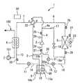
- FIG. It is a figure which shows the refrigeration cycle apparatus by Embodiment 1.
- FIG. It is a figure which shows the flow of the refrigerant at the time of the heating operation of the refrigerating cycle apparatus by Embodiment 1.
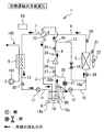
- FIG. It is a figure which shows the flow of the refrigerant at the time of the hot gas defrost operation of the refrigerating cycle apparatus by Embodiment 1.
- FIG. It is an example of the functional block diagram of the refrigeration cycle apparatus according to Embodiment 1.
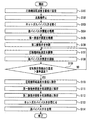
- It is a flowchart which shows the example of the process at the time of performing a hot gas defrost operation.
- It is a timing chart which shows the operation example of each actuator from the transition from the heating operation to the hot gas defrost operation to the return to the heating operation.
- FIG. 1 is a diagram showing a refrigeration cycle device 1 according to the first embodiment.
- the refrigerating cycle device 1 of the present embodiment includes a compressor 2 for compressing the refrigerant.
- the substance used as the refrigerant is not particularly limited , but may be, for example, CO 2 , HFC, or HFO.
- the refrigerating cycle device 1 may use a flammable refrigerant. Flammable refrigerants have the advantage of having a small impact on global warming. Examples of the flammable refrigerant include hydrocarbon refrigerants such as R290 (propane) and R600a (isobutane).
- the suction passage 3 is connected to the suction port of the compressor 2.
- the discharge passage 4 is connected to the discharge port of the compressor 2.
- the air heat exchanger 5 is arranged outdoors.
- the outdoor air is hereinafter referred to as "outside air”.
- the air heat exchanger 5 exchanges heat between the refrigerant and the outside air.
- the air heat exchanger 5 has a refrigerant flow path.
- the air heat exchanger 5 has a structure through which air can pass. In the illustrated example, when the blower 23 is activated, outside air flows through the air heat exchanger 5.
- the utilization heat exchanger 6 exchanges heat between the refrigerant and the heat medium.
- the heat medium is a medium for transporting heat to a heat demand unit (not shown), which is a facility or place where heat is used.
- the heat medium in this embodiment is a liquid.
- the heat medium of this liquid may be, for example, water or brine other than water.
- the utilization heat exchanger 6 in the present embodiment has a refrigerant flow path and a heat medium flow path. In the illustrated example, the heat medium flow path of the utilization heat exchanger 6 is connected to the heat demand unit via the heat medium circuit 100.
- the heat medium circuit 100 has a heat medium pump 101.
- the heat medium circuit 100 may include a valve (not shown) for controlling the flow rate or circulation path of the heat medium.
- the heat demand unit may include heating equipment for warming the room.
- the heating equipment may include, for example, at least one of a floor heating panel installed under the floor of the room, a radiator installed in the room, a panel heater, and a fan convector.
- the heat demand unit may include a heat storage tank.
- the heat storage tank may be a hot water storage tank for storing hot water.
- the heat medium heated by the utilization heat exchanger 6 may be stored in the heat storage tank, or the hot water heated by exchanging heat with the heat medium heated by the utilization heat exchanger 6 is accumulated in the hot water storage tank. You may.
- the heat demand unit may include cooling equipment for cooling the room.
- the cooling equipment may include, for example, a fan coil.
- the heat demand unit may be a unit that can be used for both heating equipment and cooling equipment.
- the heat medium in the present embodiment is not limited to a liquid, but may be a gas.
- the heat medium may be indoor air, which is the air inside the room.
- a blower (not shown) may be provided to generate an air flow so that the indoor air that has passed through the utilization heat exchanger 6 is blown into the room.
- the first refrigerant passage 7 connects one end of the refrigerant passage of the utilization heat exchanger 6 to the discharge passage 4.
- the second refrigerant passage 8 connects one end of the refrigerant passage of the air heat exchanger 5 to the suction passage 3.
- the refrigerant in the liquid phase state is referred to as “liquid refrigerant”, and the refrigerant in the gas phase state is referred to as “gas refrigerant”.
- the receiver 9 is provided to store the liquid refrigerant.
- a liquid level 90 of the liquid refrigerant is formed inside the receiver 9. The internal space of the receiver 9 above the liquid level 90 is filled with a gas refrigerant.
- the refrigeration cycle device 1 further includes a first expansion valve 11 and a second expansion valve 12.
- Each of the first expansion valve 11 and the second expansion valve 12 has a first port and a second port.
- the third refrigerant passage 13 connects the other end of the refrigerant passage of the utilization heat exchanger 6 to the first port of the first expansion valve 11.
- the fourth refrigerant passage 14 connects the second port of the first expansion valve 11 to the receiver 9.
- the fifth refrigerant passage 15 connects the receiver 9 to the first port of the second expansion valve 12.
- the sixth refrigerant passage 16 connects the second port of the second expansion valve 12 to the other end of the refrigerant flow path of the air heat exchanger 5.
- the tip opening 14a of the fourth refrigerant passage 14 is located at the lower part in the receiver 9 and below the liquid level 90.
- the tip opening 15a of the fifth refrigerant passage 15 is located at the lower part in the receiver 9, and is below the liquid level 90.
- the hot gas bypass passage 17 connects the discharge passage 4 to the sixth refrigerant passage 16. One end of the hot gas bypass passage 17 is connected to the branch portion 4a provided in the discharge passage 4. The other end of the hot gas bypass passage 17 is connected to the branch portion 16a provided in the sixth refrigerant passage 16. A hot gas bypass valve 18 is provided in the hot gas bypass passage 17.
- the internal heat exchanger 19 in the present embodiment exchanges heat between the liquid refrigerant inside the receiver 9 and the refrigerant passing through the suction passage 3.
- the internal heat exchanger 19 is provided inside the receiver 9.
- the internal heat exchanger 19 is below the liquid level 90 of the liquid refrigerant.
- the refrigerant passing through the suction passage 3 is heated by the liquid refrigerant inside the receiver 9 when passing through the internal heat exchanger 19.
- the liquid bypass passage 20 has an inlet portion 20a connected to the fifth refrigerant passage 15 and an outlet portion 20b connected to the suction passage 3 upstream of the internal heat exchanger 19.
- the inlet portion 20a is connected to a branch portion provided in the fifth refrigerant passage 15.
- the outlet portion 20b is connected to a branch portion provided in the suction passage 3.
- a liquid bypass valve 21 is provided in the liquid bypass passage 20.
- the refrigeration cycle device 1 can perform a heating operation.
- the heating operation is an operation of heating the heat medium by flowing the refrigerant discharged from the compressor 2 into the utilization heat exchanger 6.
- heating can be performed by supplying the heat medium heated by the utilization heat exchanger 6 to the heating facility by the heating operation.
- the heat demand unit includes a heat storage tank such as a hot water storage tank
- a heat storage operation in which the heat medium or hot water heated by the heating operation is stored in the heat storage tank can be performed.
- FIG. 2 is a diagram showing the flow of the refrigerant during the heating operation of the refrigeration cycle device 1 according to the first embodiment.
- the flow of the refrigerant during the heating operation is as follows.
- the hot gas bypass valve 18 and the liquid bypass valve 21 are closed, and no refrigerant flows through the hot gas bypass passage 17 and the liquid bypass passage 20.
- the high-temperature and high-pressure refrigerant discharged from the compressor 2 flows into the utilization heat exchanger 6 through the discharge passage 4 and the first refrigerant passage 7.
- the high-pressure refrigerant cooled by the heat medium in the utilization heat exchanger 6 flows into the first expansion valve 11 through the third refrigerant passage 13.
- This high-pressure refrigerant is decompressed and expanded by the first expansion valve 11 to become a medium-pressure refrigerant.
- This medium-pressure refrigerant flows from the first expansion valve 11 into the receiver 9 through the fourth refrigerant passage 14.
- the liquid refrigerant in the receiver 9 is cooled by the low-pressure refrigerant that flows through the suction passage 3 and passes through the internal heat exchanger 19.
- the medium-pressure liquid refrigerant in the receiver 9 flows into the second expansion valve 12 through the fifth refrigerant passage 15.
- the medium-pressure liquid refrigerant is decompressed and expanded by the second expansion valve 12 to become a gas-liquid two-phase low-temperature low-pressure refrigerant.
- This low-temperature low-pressure refrigerant flows into the air heat exchanger 5 through the sixth refrigerant passage 16.
- the low-temperature low-pressure refrigerant evaporates by absorbing the heat of the outside air in the air heat exchanger 5.
- Low-pressure refrigerant flows from the air heat exchanger 5 into the suction passage 3 through the second refrigerant passage 8.
- the low-pressure refrigerant flowing through the suction passage 3 is heated by the medium-pressure refrigerant in the receiver 9 when passing through the internal heat exchanger 19 on the way, and then is sucked into the compressor 2.
- FIG. 3 is a diagram showing the flow of the refrigerant during the hot gas defrost operation of the refrigeration cycle device 1 according to the first embodiment.
- the hot gas bypass valve 18 is opened, the second expansion valve 12 is closed, the first expansion valve 11 is continuously or intermittently opened, and the liquid bypass valve 21 is continuous or intermittent. Opened to.
- the flow of the refrigerant during the hot gas defrost operation is as follows. Most of the high-temperature and high-pressure refrigerant discharged from the compressor 2 to the discharge passage 4 passes through the branch portion 4a, the hot gas bypass passage 17, the hot gas bypass valve 18, the branch portion 16a, and the sixth refrigerant passage 16. , Flows into the air heat exchanger 5. Frost is melted and removed by the heat of the refrigerant, that is, the hot gas, which has flowed into the air heat exchanger 5. The refrigerant that has passed through the air heat exchanger 5 is sucked into the compressor 2 after passing through the second refrigerant passage 8, the suction passage 3, and the internal heat exchanger 19.
- the refrigerant flowing into the utilization heat exchanger 6 is cooled by the heat medium and condensed.
- the condensed liquid refrigerant collects in the utilization heat exchanger 6.
- the liquid refrigerant in the utilization heat exchanger 6 flows into the receiver 9 through the third refrigerant passage 13 and the first expansion valve 11.
- the liquid refrigerant in the receiver 9 flows from the tip opening 15a to the fifth refrigerant passage 15. This liquid refrigerant passes through the inlet portion 20a, the liquid bypass passage 20, and the outlet portion 20b, and joins the refrigerant flowing through the suction passage 3.
- the defrosting capacity decreases as a result of insufficient flow of the refrigerant circulating from the compressor 2 to the air heat exchanger 5. do.
- the following effects can be obtained during the hot gas defrost operation.
- the liquid refrigerant accumulated in the utilization heat exchanger 6 can be supplied to the suction passage 3 through the first expansion valve 11 and the liquid bypass passage 20. Therefore, it is possible to reliably prevent the shortage of the flow rate of the refrigerant circulating from the compressor 2 to the air heat exchanger 5, and it is possible to maintain a high defrosting ability.
- the liquid refrigerant flowing into the suction passage 3 from the outlet portion 20b of the liquid bypass passage 20 is heated by the internal heat exchanger 19 and evaporates. Therefore, it is possible to reliably prevent the liquid refrigerant from being sucked into the compressor 2.
- the refrigeration cycle device 1 may further include a control circuit 50 configured to perform a heating operation and a hot gas defrost operation.
- a control circuit 50 configured to perform a heating operation and a hot gas defrost operation.
- the control circuit 50 closes the hot gas bypass valve 18 and the liquid bypass valve 21.
- the control circuit 50 opens the hot gas bypass valve 18 and closes the second expansion valve 12.
- the control circuit 50 opens the liquid bypass valve 21 continuously or intermittently.
- the control circuit 50 may control the opening degree of the first expansion valve 11 during the hot gas defrost operation to be smaller than the opening degree of the first expansion valve 11 during the heating operation.
- control circuit 50 may keep the first expansion valve 11 open, or may control the first expansion valve 11 to repeatedly open and close.
- the control circuit 50 may keep the liquid bypass valve 21 open, or may control the liquid bypass valve 21 to repeatedly open and close.
- the refrigeration cycle device 1 may further include a refrigerant circuit switching valve 22 for switching between a forward cycle circuit and a reverse cycle circuit.
- the positive cycle circuit shown in FIG. 2 is a circuit in which the refrigerant discharged from the compressor 2 flows into the utilization heat exchanger 6 through the first refrigerant passage 7.
- the reverse cycle circuit is a circuit in which the refrigerant discharged from the compressor 2 flows into the air heat exchanger 5 through the second refrigerant passage 8.
- the cooling operation is an operation of cooling the heat medium with the utilization heat exchanger 6. For example, in a system in which the heat demand unit includes a cooling facility, cooling can be performed by supplying the heat medium cooled by the cooling operation from the heat exchanger 6 to the cooling facility.
- the refrigerant circuit switching valve 22 includes an a port, a b port, a c port, and a d port.
- the a port of the refrigerant circuit switching valve 22 is connected to the discharge port of the compressor 2 by the discharge passage 4.
- the b port of the refrigerant circuit switching valve 22 is connected to the suction port of the compressor 2 by the suction passage 3.
- the c port of the refrigerant circuit switching valve 22 is connected to the utilization heat exchanger 6 by the first refrigerant passage 7.
- the d port of the refrigerant circuit switching valve 22 is connected to the air heat exchanger 5 by the second refrigerant passage 8.
- the refrigerant circuit switching valve 22 switches the refrigerant flow path, for example, by moving the valve body.
- the refrigerant circuit switching valve 22 communicates the a port with the c port and the b port with the d port to form a positive cycle circuit.
- the discharge passage 4 is connected to the first refrigerant passage 7, and the suction passage 3 is connected to the second refrigerant passage 8.
- the state of the refrigerant circuit switching valve 22 during the hot gas defrost operation of FIG. 3 is also the same as described above.
- the refrigerant circuit switching valve 22 communicates the a port with the d port and the b port with the c port to form a reverse cycle circuit.
- the discharge passage 4 is connected to the second refrigerant passage 8
- the suction passage 3 is connected to the first refrigerant passage 7.
- the flow of the refrigerant during operation by this reverse cycle circuit is as follows.
- the high-temperature and high-pressure refrigerant discharged from the compressor 2 flows into the air heat exchanger 5 through the discharge passage 4 and the second refrigerant passage 8.
- the high-pressure refrigerant is cooled by the outside air in the air heat exchanger 5.
- the cooled high-pressure refrigerant flows from the air heat exchanger 5 into the second expansion valve 12 through the sixth refrigerant passage 16.
- This high-pressure refrigerant is decompressed and expanded by the second expansion valve 12 to become a medium-pressure refrigerant.
- This medium pressure refrigerant flows from the second expansion valve 12 into the receiver 9 through the fifth refrigerant passage 15.
- a medium-pressure liquid refrigerant flows from the receiver 9 into the first expansion valve 11 through the fourth refrigerant passage 14.
- the medium-pressure liquid refrigerant is decompressed and expanded by the first expansion valve 11 to become a gas-liquid two-phase low-pressure refrigerant.
- This low-pressure refrigerant flows into the utilization heat exchanger 6 through the third refrigerant passage 13.
- the heat medium is cooled by the evaporation of the low-pressure refrigerant in the used heat exchanger 6.
- the low-pressure refrigerant that has passed through the utilization heat exchanger 6 flows into the suction passage 3 from the first refrigerant passage 7.
- the low-pressure refrigerant flowing through the suction passage 3 is heated by the medium-pressure refrigerant in the receiver 9 when passing through the internal heat exchanger 19 on the way, and then is sucked into the compressor 2.
- the liquid refrigerant in the receiver 9 is cooled by the low-pressure refrigerant that flows through the suction passage 3 and passes through the internal heat exchanger 19.
- the refrigeration cycle device 1 of the present disclosure may not be provided with the refrigerant circuit switching valve 22 and may be incapable of performing reverse cycle operation.
- the discharge passage 4 may be directly connected to the first refrigerant passage 7
- the suction passage 3 may be directly connected to the second refrigerant passage 8.
- the refrigeration cycle device 1 includes a discharge pressure sensor 24, a discharge temperature sensor 25, a suction pressure sensor 26, a suction temperature sensor 27, a first temperature sensor 28, a second temperature sensor 29, and a third temperature sensor 30. , And at least one of the outside air temperature sensors 31 may be further provided.
- the discharge pressure sensor 24 installed in the discharge passage 4 detects the compressor discharge pressure, which is the pressure of the refrigerant discharged from the compressor 2.
- the discharge temperature sensor 25 installed in the discharge passage 4 detects the compressor discharge temperature, which is the temperature of the refrigerant discharged from the compressor 2.
- the suction pressure sensor 26 installed in the suction passage 3 detects the compressor suction pressure, which is the pressure of the refrigerant sucked into the compressor 2.
- the suction temperature sensor 27 installed in the suction passage 3 downstream of the internal heat exchanger 19 detects the compressor suction temperature, which is the temperature of the refrigerant sucked into the compressor 2.
- the first temperature sensor 28 installed in the sixth refrigerant passage 16 between the branch portion 16a and the air heat exchanger 5 detects the temperature of the refrigerant between the air heat exchanger 5 and the second expansion valve 12. do.
- the second temperature sensor 29 installed in the second refrigerant passage 8 detects the temperature of the refrigerant between the refrigerant circuit switching valve 22 and the air heat exchanger 5.
- the third temperature sensor 30 installed in the fourth refrigerant passage 14 detects the temperature of the liquid refrigerant between the utilization heat exchanger 6 and the first expansion valve 11.
- the outside air temperature sensor 31 detects the temperature of the outside air before it flows into the air heat exchanger 5.
- FIG. 4 is an example of a functional block diagram of the refrigeration cycle device 1 according to the first embodiment.
- Each of the sensor 25, the suction pressure sensor 26, the suction temperature sensor 27, the first temperature sensor 28, the second temperature sensor 29, the third temperature sensor 30, and the outside air temperature sensor 31 are electrically connected to the control circuit 50. You may.
- Each function of the control circuit 50 may be realized by a processing circuit.
- the processing circuit of the control circuit 50 may include at least one processor 51 and at least one memory 52.
- At least one processor 51 may realize each function of the control circuit 50 by reading and executing a program stored in at least one memory 52.
- the processing circuit of the control circuit 50 may include at least one dedicated hardware.
- the control circuit 50 may be controlled so that the rotation speed of the compressor 2 is variable, for example, by inverter control.
- the control circuit 50 may be controlled so that the rotation speed of the blower 23 is variable, for example, by inverter control.
- the hot gas bypass valve 18 is preferably composed of, for example, a solenoid valve having a small pressure loss that can be switched only between open (fully open) and closed (fully closed).
- the liquid bypass valve 21 has a function as an expansion valve capable of adjusting the flow rate by adjusting the opening degree thereof, for example.
- the operation of the heat medium pump 101 of the heat medium circuit 100 may be controlled by a controller other than the control circuit 50.
- a controller included in an air conditioner or a hot water supply device using a heat medium may control the operation of the heat medium pump 101.
- the refrigerating cycle apparatus 1 may be configured to execute the hot gas defrost operation without stopping the flow of the heat medium in the utilization heat exchanger 6. In the present embodiment, it is not necessary to stop the heat medium pump 101 when executing the hot gas defrost operation, so that the control operation becomes simple. If the heat medium continues to flow into the used heat exchanger 6 during the hot gas defrost operation, the high-temperature high-pressure refrigerant from the compressor 2 is cooled by the heat medium and condensed, so that the liquid is contained in the used heat exchanger 6. Refrigerant is easily generated. In the present embodiment, the liquid refrigerant in the utilization heat exchanger 6 can be supplied to the suction passage 3 through the first expansion valve 11 and the liquid bypass passage 20.
- the heating capacity [W] is the amount of heat given to the heat medium by the heat exchanger 6 used per unit time during the heating operation.
- the control circuit 50 may adjust the rotation speed of the compressor 2 so that a predetermined heating capacity corresponding to the load of the heat medium circuit 100 can be obtained.
- the degree of superheat of the refrigerant sucked into the compressor 2 is hereinafter referred to as “suction superheat”.
- the degree of superheat of the refrigerant discharged from the compressor 2 is hereinafter referred to as “discharge superheat”.
- the saturation temperature corresponding to the compressor suction pressure is hereinafter referred to as “suction saturation temperature”.
- the saturation temperature corresponding to the compressor discharge pressure is hereinafter referred to as “discharge saturation temperature”.
- the control circuit 50 can calculate the suction saturation temperature using the detection pressure of the suction pressure sensor 26.
- the control circuit 50 can calculate the discharge saturation temperature using the detection pressure of the discharge pressure sensor 24.
- the control circuit 50 can calculate the suction superheat degree from the difference between the detection temperature of the suction temperature sensor 27 and the suction saturation temperature.
- the suction pressure sensor 26 and the suction temperature sensor 27 correspond to a detector that detects the degree of suction superheat.
- the control circuit 50 can calculate the degree of discharge superheat from the difference between the detection temperature of the discharge temperature sensor 25 and the discharge saturation temperature.
- the discharge pressure sensor 24 and the discharge temperature sensor 25 correspond to a detector that detects the degree of discharge superheat.
- the control circuit 50 may control the opening degree of the first expansion valve 11 so that the degree of supercooling of the refrigerant flowing out from the utilization heat exchanger 6 approaches the target.
- the control circuit 50 may calculate this degree of supercooling from the difference between the discharge saturation temperature and the detection temperature of the third temperature sensor 30. For example, when the control circuit 50 increases the opening degree of the first expansion valve 11, the flow rate of the refrigerant passing through the utilization heat exchanger 6 increases, and the degree of supercooling decreases.
- control circuit 50 may control the opening degree of the second expansion valve 12 so that the suction superheat degree or the discharge superheat degree approaches the target.
- the control circuit 50 may control the second expansion valve 12 using either the suction superheat degree or the discharge superheat degree.
- the temperature of the refrigerant flowing out of the air heat exchanger 5 is referred to as the “refrigerant outlet temperature of the air heat exchanger 5", and the temperature of the refrigerant flowing into the air heat exchanger 5 is referred to as the “air heat exchanger 5". It is called “refrigerant inlet temperature”.
- the control circuit 50 may control the opening degree of the second expansion valve 12 so that the degree of evaporation superheat approaches the target.
- the degree of evaporation superheat corresponds to the difference between the refrigerant outlet temperature of the air heat exchanger 5 detected by the second temperature sensor 29 and the refrigerant inlet temperature of the air heat exchanger 5 detected by the first temperature sensor 28.
- control circuit 50 When the control circuit 50 increases the opening degree of the second expansion valve 12 during the heating operation, the flow rate of the refrigerant passing through the air heat exchanger 5 increases, and the suction superheat degree, the discharge superheat degree, and the evaporation superheat degree, respectively. Decreases.
- the control circuit 50 may operate the blower 23 at a predetermined rotation speed.
- FIG. 5 is a flowchart showing an example of processing when the hot gas defrost operation is executed.
- FIG. 6 is a timing chart showing an operation example of each actuator from the heating operation to the hot gas defrost operation and the return to the heating operation.
- FIGS. 5 and 6 will be described.
- the control circuit 50 may control to shift from the heating operation to the hot gas defrost operation when the difference between the outside air temperature and the temperature of the liquid refrigerant of the air heat exchanger 5 becomes larger than the reference value.
- This reference value may be, for example, about 10K.
- the control circuit 50 When shifting from the heating operation to the hot gas defrost operation, the control circuit 50 first controls the operation as step S101 of FIG. 5 so that the rotation speed of the compressor 2 becomes equal to the minimum rotation speed Fcmin. Next, the control circuit 50 stops the blower 23 in step S102. Next, the control circuit 50 opens the hot gas bypass valve 18 as step S103. Next, in step S104, the control circuit 50 controls the operation so that the opening degree of the liquid bypass valve 21 is slightly opened (P3-1). This slight opening (P3-1) preferably corresponds to the minimum opening degree at which the refrigerant flows through the liquid bypass valve 21. Next, in step S105, the control circuit 50 controls the operation so that the opening degree of the first expansion valve 11 is slightly opened (P1-2).
- step S106 the control circuit 50 controls the operation so that the opening degree of the second expansion valve 12 is fully closed. As a result, the refrigerant does not flow to the second expansion valve 12.
- the process from step S101 to step S106 corresponds to the defrost preparation process in FIG.
- step S106 the control circuit 50 controls the operation as step S107 so that the rotation speed of the compressor 2 becomes equal to the target rotation speed Fc2.
- the target rotation speed Fc2 may be a fixed value.
- the control circuit 50 may adjust the value of the target rotation speed Fc2 so that the compressor discharge pressure becomes constant, for example.
- step S108 the control circuit 50 controls the operation so that the opening degree of the liquid bypass valve 21 becomes equal to the target opening degree (P3-2). At this time, the control circuit 50 may adjust the value of the target opening degree (P3-2) so that the suction superheat degree or the discharge superheat degree approaches the target.
- the opening of the first expansion valve 11 is slightly open (P1-2) during the hot gas defrost operation, only a small amount of the high-temperature and high-pressure refrigerant discharged from the compressor 2 to the discharge passage 4 uses heat. It flows to the exchanger 6 and most of the refrigerant flows to the hot gas bypass passage 17.
- the high-temperature high-pressure refrigerant that has flowed into the hot gas bypass passage 17 is decompressed to become a low-pressure gas refrigerant when passing through the hot gas bypass valve 18, and then flows into the air heat exchanger 5.
- the low-pressure gas refrigerant flows into the pipe forming the refrigerant flow path of the air heat exchanger 5 and reaches the surface of the fin joined to the pipe. Exchanges heat with attached frost. Frost receives the heat of the refrigerant and melts. The refrigerant is cooled by frost.
- the refrigerant exiting the air heat exchanger 5 flows into the suction passage 3 through the second refrigerant passage 8 and the refrigerant circuit switching valve 22.
- the refrigerant flowing into the suction passage 3 merges with the refrigerant from the liquid bypass passage 20.
- the combined refrigerant is heated by exchanging heat with the refrigerant in the receiver 9 by the internal heat exchanger 19, and then sucked into the compressor 2 again.
- a hot gas defrost circuit that circulates the refrigerant in the order of the compressor 2, the hot gas bypass valve 18, the air heat exchanger 5, the refrigerant circuit switching valve 22, and the internal heat exchanger 19 is formed.
- the opening degree of the first expansion valve 11 is slightly open (P1-2) during the hot gas defrost operation, a small amount of high-pressure refrigerant is used from the discharge passage 4 through the first refrigerant passage 7 to the heat exchanger 6. Inflow to.
- the high-pressure refrigerant is cooled and liquefied.
- This liquefied refrigerant passes through the first expansion valve 11 and flows into the receiver 9. Since the liquid bypass valve 21 is open, the liquid refrigerant from the receiver 9 flows into the suction passage 3 through the liquid bypass passage 20.
- the control circuit 50 determines in step S109 whether the refrigerant outlet temperature of the air heat exchanger 5 detected by the second temperature sensor 29 is higher than the reference temperature.
- This reference temperature is a temperature for determining the end of the hot gas defrost operation, and may be a temperature of 0 ° C. or higher at which the frost melts.
- the refrigerant outlet temperature of the air heat exchanger 5 is equal to or lower than the reference temperature, it can be determined that the frost has not been removed yet, so that the control circuit 50 returns to the process of step S107 and continues the hot gas defrost operation. ..
- control circuit 50 proceeds to the process of step S110 in order to end the hot gas defrost operation and restart the heating operation.
- step S110 the control circuit 50 controls the operation so that the rotation speed of the compressor 2 becomes equal to the minimum rotation speed Fcmin.
- step S111 the control circuit 50 controls the operation so that the opening degree of the first expansion valve 11 becomes the initial opening degree (P1-3) of the heating operation.
- step S112 the control circuit 50 controls the operation so that the opening degree of the second expansion valve 12 becomes the initial opening degree (P2-3) of the heating operation.
- step S113 the control circuit 50 closes the hot gas bypass valve 18 as step S113.
- step S114 the control circuit 50 fully closes the liquid bypass valve 21 in step S114.
- the process from step S110 to step S114 corresponds to the return process in FIG.
- the heating operation is restarted by this restoration process.
- the control circuit 50 operates the blower 23 again at a predetermined rotation speed, and operates the compressor 2, the first expansion valve 11, and the second expansion valve 12 in the heating operation described above. Control as described in.
- the refrigeration cycle device 1 of the present embodiment may be configured so that the reverse cycle defrost operation can be further executed.
- the reverse cycle defrost operation is an operation of removing frost from the air heat exchanger 5 by circulating the refrigerant in the reverse cycle circuit as in the cooling operation described above.
- the air heat exchanger 5 is used as a condenser and the utilization heat exchanger 6 is used as an evaporator.
- the heat medium in the utilization heat exchanger 6 is cooled to a temperature lower than the freezing point by the heat of vaporization of the refrigerant. May freeze. If the heat medium in the used heat exchanger 6 freezes and expands in volume, the used heat exchanger 6 may be destroyed. If the used heat exchanger 6 is destroyed, the wall separating the heat medium flow path and the refrigerant flow path may be broken, and the refrigerant may leak into the heat medium circuit 100 or the refrigerant may leak into the atmosphere.
- a heat medium that can freeze such as water
- a temperature sensor (not shown) for detecting the temperature of the heat medium is provided, and the control circuit 50 is used when melting the frost adhering to the air heat exchanger 5.
- the control circuit 50 is used when melting the frost adhering to the air heat exchanger 5.
- the hot gas defrost operation is executed when the heat medium in the utilization heat exchanger 6 may freeze, and vice versa when there is no possibility that the heat medium in the utilization heat exchanger 6 freezes. Since the cycle defrost operation is executed, both can be used more appropriately.
- the refrigeration cycle device 1 using a flammable refrigerant it is particularly important to reliably prevent the refrigerant from leaking into the heat medium circuit 100 or into the atmosphere.
- the hot gas defrost operation can be executed, it is possible to surely prevent the heat medium in the heat exchanger 6 from freezing. Therefore, since it is possible to reliably prevent the leakage of the refrigerant into the heat medium circuit 100 or the leakage of the refrigerant into the atmosphere, it is suitable for the use of a flammable refrigerant.
- the opening degree of the first expansion valve 11 during the hot gas defrost operation may be any opening degree that allows the liquid refrigerant accumulated in the utilization heat exchanger 6 to be moved to the receiver 9 side through the fourth refrigerant passage 14. ..
- the opening degree of the first expansion valve 11 during the hot gas defrost operation is smaller than the opening degree of the first expansion valve 11 during the heating operation.
- the refrigerant can be supplied from the receiver 9 to the hot gas defrost circuit through the liquid bypass valve 21, it is possible to reliably prevent the amount of refrigerant in the hot gas defrost circuit from becoming insufficient.
- the second expansion valve 12 is opened and the liquid refrigerant flows from the receiver 9 through the sixth refrigerant passage 16 into the air heat exchanger 5, so that the refrigerant is supplied from the receiver 9 to the hot gas defrost circuit. It is assumed that it has been supplied. In this case, the temperature of the refrigerant flowing into the air heat exchanger 5 is lowered by mixing the gas refrigerant from the hot gas bypass passage 17 and the liquid refrigerant from the receiver 9. As a result, the amount of heat used for defrosting the air heat exchanger 5 is reduced.
- the amount of heat used for defrosting the air heat exchanger 5 is not reduced, and the hot gas defrost circuit is used.
- the amount of refrigerant can be adjusted.
- control circuit 50 may control the operation or opening degree of the liquid bypass valve 21 so that the suction superheat degree approaches the target. By doing so, it is possible to more reliably prevent the amount of the liquid refrigerant flowing from the liquid bypass passage 20 into the suction passage 3 from becoming too large, and thus it is possible to more reliably prevent the compressor 2 from sucking the liquid refrigerant. can.
- control circuit 50 may control the operation or opening degree of the liquid bypass valve 21 so that the discharge superheat degree approaches the target. By doing so, it is possible to more reliably prevent the amount of the liquid refrigerant flowing from the liquid bypass passage 20 into the suction passage 3 from becoming too large, and thus it is possible to more reliably prevent the compressor 2 from sucking the liquid refrigerant. can.
- the amount of refrigerant in the hot gas defrost circuit can be adjusted by one actuator (liquid bypass valve 21) and one control target (intake superheat degree or discharge superheat degree). .. Therefore, the control can be simplified and the hot gas defrost operation can be made more stable.
- the inlet portion 20a of the liquid bypass passage 20 may be directly connected to the lower part of the receiver 9. In this case, during the hot gas defrost operation, the liquid refrigerant flowing out from the lower part of the receiver 9 to the liquid bypass passage 20 can flow into the suction passage 3.
- the inlet portion 20a of the liquid bypass passage 20 may be connected to the fourth refrigerant passage 14.
- the liquid refrigerant in the fourth refrigerant passage 14 can flow into the suction passage 3 through the liquid bypass passage 20.
- Connecting the tube directly to a container such as the receiver 9 tends to be more costly than connecting the tube to the tube.
- the inlet portion 20a of the liquid bypass passage 20 is connected to the fourth refrigerant passage 14, or when the inlet portion 20a of the liquid bypass passage 20 is connected to the fifth refrigerant passage 15 as shown in the illustrated example. Since it is not necessary to directly connect the pipe forming the liquid bypass passage 20 to the receiver 9, it is advantageous in cost reduction.
- the refrigeration cycle device 1 includes an internal heat exchanger that exchanges heat between the refrigerant passing through the fourth refrigerant passage 14 and the refrigerant passing through the suction passage 3 instead of the internal heat exchanger 19 shown in the figure. May be. That is, the internal heat exchanger may be outside the receiver 9. This modification also has the same effect as that of the illustrated embodiment.
- the control circuit 50 may control the operation or opening degree of the liquid bypass valve 21 according to the refrigerant outlet temperature of the air heat exchanger 5.
- the gas refrigerant is cooled by the air heat exchanger 5, so if the amount of refrigerant in the hot gas defrost circuit is large, the refrigerant may condense on the downstream side of the air heat exchanger 5. .. If the refrigerant condenses on the downstream side of the air heat exchanger 5, the internal heat exchanger 19 may not be able to completely evaporate the liquid refrigerant in the suction passage 3.
- the control circuit 50 controls the operation or opening degree of the liquid bypass valve 21 so that the refrigerant flowing out of the air heat exchanger 5 is in the state of superheated gas. Thereby, the amount of the refrigerant in the hot gas defrost circuit may be adjusted. This makes it possible to more reliably prevent the liquid refrigerant from being sucked into the compressor 2.
- the difference between the refrigerant outlet temperature of the air heat exchanger 5 detected by the second temperature sensor 29 and the suction saturation temperature corresponds to the degree of overheating of the refrigerant flowing out of the air heat exchanger 5.
- the control circuit 50 may control the operation or opening degree of the liquid bypass valve 21 so that the degree of superheat of the refrigerant flowing out of the air heat exchanger 5 approaches the target. For example, when the control circuit 50 increases the opening degree of the liquid bypass valve 21, the amount of the refrigerant in the hot gas defrost circuit increases, so that the degree of superheat of the refrigerant flowing out of the air heat exchanger 5 decreases. On the contrary, when the control circuit 50 reduces the opening degree of the liquid bypass valve 21, the degree of superheat of the refrigerant flowing out from the air heat exchanger 5 increases.
- the control circuit 50 determines the refrigerant inlet temperature of the air heat exchanger 5 detected by the first temperature sensor 28 and the refrigerant outlet temperature of the air heat exchanger 5 detected by the second temperature sensor 29.
- the operation or opening degree of the liquid bypass valve 21 may be controlled according to the temperature difference between the two. When the control circuit 50 increases the opening degree of the liquid bypass valve 21, the temperature difference increases, and when the control circuit 50 decreases the opening degree of the liquid bypass valve 21, the temperature difference decreases.
- the control circuit 50 may temporarily increase the opening degree of the first expansion valve 11 according to the temperature of the liquid refrigerant flowing out from the utilization heat exchanger 6.
- the temperature of the refrigerant drops to a temperature lower than the discharge saturation temperature. The lower the refrigerant temperature, the more refrigerant is condensed in the utilization heat exchanger 6.
- the control circuit 50 is used by temporarily increasing the opening degree of the first expansion valve 11 when the degree of supercooling of the liquid refrigerant flowing out from the utilization heat exchanger 6 becomes larger than the standard.
- a temperature sensor may be installed to detect the temperature of the heat medium flowing into the used heat exchanger 6 or the temperature of the heat medium flowing out of the used heat exchanger 6.
- the control circuit 50 exchanges heat when the difference between the heat medium temperature detected by the temperature sensor and the temperature of the liquid refrigerant flowing out of the heat exchanger 6 becomes smaller than the standard. It may be determined that the amount of condensation of the refrigerant in the vessel 6 has increased, and the opening degree of the first expansion valve 11 may be temporarily increased.
- 1 refrigeration cycle device 2 compressor, 3 suction passage, 4 discharge passage, 4a branch, 5 air heat exchanger, 6 heat exchanger used, 7 first refrigerant passage, 8 second refrigerant passage, 9 receiver, 11th 1 expansion valve, 12 2nd expansion valve, 13 3rd refrigerant passage, 14 4th refrigerant passage, 14a tip opening, 15 5th refrigerant passage, 15a tip opening, 16 6th refrigerant passage, 16a branch, 17 hot gas bypass Passage, 18 hot gas bypass valve, 19 internal heat exchanger, 20 liquid bypass passage, 20a inlet, 20b outlet, 21 liquid bypass valve, 22 refrigerant circuit switching valve, 23 blower, 24 discharge pressure sensor, 25 discharge temperature sensor , 26 suction pressure sensor, 27 suction temperature sensor, 28 first temperature sensor, 29 second temperature sensor, 30 third temperature sensor, 31 outside air temperature sensor, 50 control circuit, 51 processor, 52 memory, 90 liquid level, 100 heat Medium circuit, 101 heat medium pump
Landscapes
- Engineering & Computer Science (AREA)
- Physics & Mathematics (AREA)
- Mechanical Engineering (AREA)
- Thermal Sciences (AREA)
- General Engineering & Computer Science (AREA)
- Compression-Type Refrigeration Machines With Reversible Cycles (AREA)
- Heat-Pump Type And Storage Water Heaters (AREA)
- Air Conditioning Control Device (AREA)
Priority Applications (5)
| Application Number | Priority Date | Filing Date | Title |
|---|---|---|---|
| PCT/JP2020/021799 WO2021245795A1 (ja) | 2020-06-02 | 2020-06-02 | 冷凍サイクル装置 |
| JP2022528413A JP7416238B2 (ja) | 2020-06-02 | 2020-10-12 | 冷凍サイクル装置 |
| PCT/JP2020/038476 WO2021245958A1 (ja) | 2020-06-02 | 2020-10-12 | 冷凍サイクル装置 |
| US17/911,702 US20230134655A1 (en) | 2020-06-02 | 2020-10-12 | Refrigeration cycle device |
| EP20938818.0A EP4160108A4 (en) | 2020-06-02 | 2020-10-12 | Refrigeration cycle device |
Applications Claiming Priority (1)
| Application Number | Priority Date | Filing Date | Title |
|---|---|---|---|
| PCT/JP2020/021799 WO2021245795A1 (ja) | 2020-06-02 | 2020-06-02 | 冷凍サイクル装置 |
Publications (1)
| Publication Number | Publication Date |
|---|---|
| WO2021245795A1 true WO2021245795A1 (ja) | 2021-12-09 |
Family
ID=78830309
Family Applications (2)
| Application Number | Title | Priority Date | Filing Date |
|---|---|---|---|
| PCT/JP2020/021799 Ceased WO2021245795A1 (ja) | 2020-06-02 | 2020-06-02 | 冷凍サイクル装置 |
| PCT/JP2020/038476 Ceased WO2021245958A1 (ja) | 2020-06-02 | 2020-10-12 | 冷凍サイクル装置 |
Family Applications After (1)
| Application Number | Title | Priority Date | Filing Date |
|---|---|---|---|
| PCT/JP2020/038476 Ceased WO2021245958A1 (ja) | 2020-06-02 | 2020-10-12 | 冷凍サイクル装置 |
Country Status (4)
| Country | Link |
|---|---|
| US (1) | US20230134655A1 (https=) |
| EP (1) | EP4160108A4 (https=) |
| JP (1) | JP7416238B2 (https=) |
| WO (2) | WO2021245795A1 (https=) |
Families Citing this family (3)
| Publication number | Priority date | Publication date | Assignee | Title |
|---|---|---|---|---|
| US20230144675A1 (en) * | 2021-11-08 | 2023-05-11 | Carrier Corporation | Preventing icing in an hvac system |
| CN114680360B (zh) * | 2022-03-04 | 2023-06-16 | 青岛海尔空调电子有限公司 | 用于烟草的烘干系统和用于烟草的控制方法 |
| JP2024123929A (ja) * | 2023-03-02 | 2024-09-12 | Smc株式会社 | 半導体製造装置用温調装置 |
Citations (2)
| Publication number | Priority date | Publication date | Assignee | Title |
|---|---|---|---|---|
| JP2002098451A (ja) * | 2000-09-22 | 2002-04-05 | Denso Corp | ヒートポンプ式空調装置 |
| JP2010164257A (ja) * | 2009-01-16 | 2010-07-29 | Mitsubishi Electric Corp | 冷凍サイクル装置及び冷凍サイクル装置の制御方法 |
Family Cites Families (7)
| Publication number | Priority date | Publication date | Assignee | Title |
|---|---|---|---|---|
| WO2009001535A1 (ja) * | 2007-06-22 | 2008-12-31 | Panasonic Corporation | 冷凍サイクル装置 |
| JP5865561B1 (ja) * | 2014-06-27 | 2016-02-17 | 三菱電機株式会社 | 冷凍サイクル装置 |
| JP6509368B2 (ja) | 2015-11-18 | 2019-05-08 | 三菱電機株式会社 | ヒートポンプ給湯装置 |
| JP6848395B2 (ja) | 2016-11-30 | 2021-03-24 | ダイキン工業株式会社 | 冷凍装置 |
| WO2018148096A1 (en) * | 2017-02-08 | 2018-08-16 | The Delfield Company, Llc | Small refrigerant receiver for use with thermostatic expansion valve refrigeration system |
| JP6846685B2 (ja) | 2017-07-05 | 2021-03-24 | パナソニックIpマネジメント株式会社 | 空気調和装置 |
| JP6925528B2 (ja) * | 2018-06-15 | 2021-08-25 | 三菱電機株式会社 | 冷凍サイクル装置 |
-
2020
- 2020-06-02 WO PCT/JP2020/021799 patent/WO2021245795A1/ja not_active Ceased
- 2020-10-12 WO PCT/JP2020/038476 patent/WO2021245958A1/ja not_active Ceased
- 2020-10-12 US US17/911,702 patent/US20230134655A1/en not_active Abandoned
- 2020-10-12 JP JP2022528413A patent/JP7416238B2/ja active Active
- 2020-10-12 EP EP20938818.0A patent/EP4160108A4/en not_active Withdrawn
Patent Citations (2)
| Publication number | Priority date | Publication date | Assignee | Title |
|---|---|---|---|---|
| JP2002098451A (ja) * | 2000-09-22 | 2002-04-05 | Denso Corp | ヒートポンプ式空調装置 |
| JP2010164257A (ja) * | 2009-01-16 | 2010-07-29 | Mitsubishi Electric Corp | 冷凍サイクル装置及び冷凍サイクル装置の制御方法 |
Also Published As
| Publication number | Publication date |
|---|---|
| EP4160108A4 (en) | 2023-11-08 |
| EP4160108A1 (en) | 2023-04-05 |
| JP7416238B2 (ja) | 2024-01-17 |
| WO2021245958A1 (ja) | 2021-12-09 |
| US20230134655A1 (en) | 2023-05-04 |
| JPWO2021245958A1 (https=) | 2021-12-09 |
Similar Documents
| Publication | Publication Date | Title |
|---|---|---|
| CN211739592U (zh) | 连续制热的空调系统 | |
| RU2480684C2 (ru) | Способ и устройство размораживания горячим паром | |
| JP4812606B2 (ja) | 空気調和装置 | |
| CN102725597B (zh) | 集装箱用冷冻装置 | |
| CN101449117B (zh) | 冷冻装置 | |
| JP5434460B2 (ja) | ヒートポンプ装置 | |
| JPH0799297B2 (ja) | 空気調和機 | |
| JP7416238B2 (ja) | 冷凍サイクル装置 | |
| CN103765133A (zh) | 制冷循环装置和具备该制冷循环装置的空气调节机 | |
| KR20130114154A (ko) | 냉동 사이클 장치 | |
| JP5062039B2 (ja) | 冷凍装置 | |
| JP2009109110A (ja) | 冷凍装置 | |
| WO2022180718A1 (ja) | 冷凍サイクル装置 | |
| JP3484131B2 (ja) | 冷凍冷蔵庫 | |
| JP2014081180A (ja) | ヒートポンプ装置 | |
| JP6137262B2 (ja) | 冷凍装置 | |
| JP2009293887A (ja) | 冷凍装置 | |
| JP2010139098A (ja) | 冷凍サイクル装置及びこれを搭載した給湯機 | |
| CN118328604A (zh) | 空调器的补气控制方法、空调器、控制器和存储介质 | |
| JP2004347272A (ja) | 冷凍装置 | |
| CN117663551A (zh) | 制冷设备及其制冷系统、控制方法、控制装置、存储介质 | |
| JP2018173195A (ja) | 冷凍装置 | |
| CN219160502U (zh) | 空调器 | |
| JP2006098044A (ja) | 冷凍装置 | |
| JP6119804B2 (ja) | 負荷冷却器のデフロスト方法 |
Legal Events
| Date | Code | Title | Description |
|---|---|---|---|
| 121 | Ep: the epo has been informed by wipo that ep was designated in this application |
Ref document number: 20939042 Country of ref document: EP Kind code of ref document: A1 |
|
| NENP | Non-entry into the national phase |
Ref country code: DE |
|
| 122 | Ep: pct application non-entry in european phase |
Ref document number: 20939042 Country of ref document: EP Kind code of ref document: A1 |
|
| NENP | Non-entry into the national phase |
Ref country code: JP |