WO2021240193A1 - 電動車両の制御方法、及び電動車両の制御システム - Google Patents
電動車両の制御方法、及び電動車両の制御システム Download PDFInfo
- Publication number
- WO2021240193A1 WO2021240193A1 PCT/IB2020/000515 IB2020000515W WO2021240193A1 WO 2021240193 A1 WO2021240193 A1 WO 2021240193A1 IB 2020000515 W IB2020000515 W IB 2020000515W WO 2021240193 A1 WO2021240193 A1 WO 2021240193A1
- Authority
- WO
- WIPO (PCT)
- Prior art keywords
- motor
- torque
- command value
- inverter
- drive
- Prior art date
- Legal status (The legal status is an assumption and is not a legal conclusion. Google has not performed a legal analysis and makes no representation as to the accuracy of the status listed.)
- Ceased
Links
Images






Classifications
-
- B—PERFORMING OPERATIONS; TRANSPORTING
- B60—VEHICLES IN GENERAL
- B60L—PROPULSION OF ELECTRICALLY-PROPELLED VEHICLES; SUPPLYING ELECTRIC POWER FOR AUXILIARY EQUIPMENT OF ELECTRICALLY-PROPELLED VEHICLES; ELECTRODYNAMIC BRAKE SYSTEMS FOR VEHICLES IN GENERAL; MAGNETIC SUSPENSION OR LEVITATION FOR VEHICLES; MONITORING OPERATING VARIABLES OF ELECTRICALLY-PROPELLED VEHICLES; ELECTRIC SAFETY DEVICES FOR ELECTRICALLY-PROPELLED VEHICLES
- B60L15/00—Methods, circuits, or devices for controlling the traction-motor speed of electrically-propelled vehicles
- B60L15/20—Methods, circuits, or devices for controlling the traction-motor speed of electrically-propelled vehicles for control of the vehicle or its driving motor to achieve a desired performance, e.g. speed, torque, programmed variation of speed
- B60L15/2036—Electric differentials, e.g. for supporting steering vehicles
-
- B—PERFORMING OPERATIONS; TRANSPORTING
- B60—VEHICLES IN GENERAL
- B60L—PROPULSION OF ELECTRICALLY-PROPELLED VEHICLES; SUPPLYING ELECTRIC POWER FOR AUXILIARY EQUIPMENT OF ELECTRICALLY-PROPELLED VEHICLES; ELECTRODYNAMIC BRAKE SYSTEMS FOR VEHICLES IN GENERAL; MAGNETIC SUSPENSION OR LEVITATION FOR VEHICLES; MONITORING OPERATING VARIABLES OF ELECTRICALLY-PROPELLED VEHICLES; ELECTRIC SAFETY DEVICES FOR ELECTRICALLY-PROPELLED VEHICLES
- B60L9/00—Electric propulsion with power supply external to the vehicle
- B60L9/16—Electric propulsion with power supply external to the vehicle using AC induction motors
- B60L9/18—Electric propulsion with power supply external to the vehicle using AC induction motors fed from DC supply lines
-
- B—PERFORMING OPERATIONS; TRANSPORTING
- B60—VEHICLES IN GENERAL
- B60L—PROPULSION OF ELECTRICALLY-PROPELLED VEHICLES; SUPPLYING ELECTRIC POWER FOR AUXILIARY EQUIPMENT OF ELECTRICALLY-PROPELLED VEHICLES; ELECTRODYNAMIC BRAKE SYSTEMS FOR VEHICLES IN GENERAL; MAGNETIC SUSPENSION OR LEVITATION FOR VEHICLES; MONITORING OPERATING VARIABLES OF ELECTRICALLY-PROPELLED VEHICLES; ELECTRIC SAFETY DEVICES FOR ELECTRICALLY-PROPELLED VEHICLES
- B60L2220/00—Electrical machine types; Structures or applications thereof
- B60L2220/40—Electrical machine applications
- B60L2220/42—Electrical machine applications with use of more than one motor
-
- B—PERFORMING OPERATIONS; TRANSPORTING
- B60—VEHICLES IN GENERAL
- B60L—PROPULSION OF ELECTRICALLY-PROPELLED VEHICLES; SUPPLYING ELECTRIC POWER FOR AUXILIARY EQUIPMENT OF ELECTRICALLY-PROPELLED VEHICLES; ELECTRODYNAMIC BRAKE SYSTEMS FOR VEHICLES IN GENERAL; MAGNETIC SUSPENSION OR LEVITATION FOR VEHICLES; MONITORING OPERATING VARIABLES OF ELECTRICALLY-PROPELLED VEHICLES; ELECTRIC SAFETY DEVICES FOR ELECTRICALLY-PROPELLED VEHICLES
- B60L2240/00—Control parameters of input or output; Target parameters
- B60L2240/40—Drive Train control parameters
- B60L2240/42—Drive Train control parameters related to electric machines
- B60L2240/421—Speed
-
- B—PERFORMING OPERATIONS; TRANSPORTING
- B60—VEHICLES IN GENERAL
- B60L—PROPULSION OF ELECTRICALLY-PROPELLED VEHICLES; SUPPLYING ELECTRIC POWER FOR AUXILIARY EQUIPMENT OF ELECTRICALLY-PROPELLED VEHICLES; ELECTRODYNAMIC BRAKE SYSTEMS FOR VEHICLES IN GENERAL; MAGNETIC SUSPENSION OR LEVITATION FOR VEHICLES; MONITORING OPERATING VARIABLES OF ELECTRICALLY-PROPELLED VEHICLES; ELECTRIC SAFETY DEVICES FOR ELECTRICALLY-PROPELLED VEHICLES
- B60L2240/00—Control parameters of input or output; Target parameters
- B60L2240/40—Drive Train control parameters
- B60L2240/42—Drive Train control parameters related to electric machines
- B60L2240/423—Torque
-
- B—PERFORMING OPERATIONS; TRANSPORTING
- B60—VEHICLES IN GENERAL
- B60L—PROPULSION OF ELECTRICALLY-PROPELLED VEHICLES; SUPPLYING ELECTRIC POWER FOR AUXILIARY EQUIPMENT OF ELECTRICALLY-PROPELLED VEHICLES; ELECTRODYNAMIC BRAKE SYSTEMS FOR VEHICLES IN GENERAL; MAGNETIC SUSPENSION OR LEVITATION FOR VEHICLES; MONITORING OPERATING VARIABLES OF ELECTRICALLY-PROPELLED VEHICLES; ELECTRIC SAFETY DEVICES FOR ELECTRICALLY-PROPELLED VEHICLES
- B60L2240/00—Control parameters of input or output; Target parameters
- B60L2240/40—Drive Train control parameters
- B60L2240/52—Drive Train control parameters related to converters
- B60L2240/526—Operating parameters
-
- B—PERFORMING OPERATIONS; TRANSPORTING
- B60—VEHICLES IN GENERAL
- B60L—PROPULSION OF ELECTRICALLY-PROPELLED VEHICLES; SUPPLYING ELECTRIC POWER FOR AUXILIARY EQUIPMENT OF ELECTRICALLY-PROPELLED VEHICLES; ELECTRODYNAMIC BRAKE SYSTEMS FOR VEHICLES IN GENERAL; MAGNETIC SUSPENSION OR LEVITATION FOR VEHICLES; MONITORING OPERATING VARIABLES OF ELECTRICALLY-PROPELLED VEHICLES; ELECTRIC SAFETY DEVICES FOR ELECTRICALLY-PROPELLED VEHICLES
- B60L2260/00—Operating Modes
- B60L2260/20—Drive modes; Transition between modes
-
- B—PERFORMING OPERATIONS; TRANSPORTING
- B60—VEHICLES IN GENERAL
- B60L—PROPULSION OF ELECTRICALLY-PROPELLED VEHICLES; SUPPLYING ELECTRIC POWER FOR AUXILIARY EQUIPMENT OF ELECTRICALLY-PROPELLED VEHICLES; ELECTRODYNAMIC BRAKE SYSTEMS FOR VEHICLES IN GENERAL; MAGNETIC SUSPENSION OR LEVITATION FOR VEHICLES; MONITORING OPERATING VARIABLES OF ELECTRICALLY-PROPELLED VEHICLES; ELECTRIC SAFETY DEVICES FOR ELECTRICALLY-PROPELLED VEHICLES
- B60L2260/00—Operating Modes
- B60L2260/20—Drive modes; Transition between modes
- B60L2260/28—Four wheel or all wheel drive
-
- Y—GENERAL TAGGING OF NEW TECHNOLOGICAL DEVELOPMENTS; GENERAL TAGGING OF CROSS-SECTIONAL TECHNOLOGIES SPANNING OVER SEVERAL SECTIONS OF THE IPC; TECHNICAL SUBJECTS COVERED BY FORMER USPC CROSS-REFERENCE ART COLLECTIONS [XRACs] AND DIGESTS
- Y02—TECHNOLOGIES OR APPLICATIONS FOR MITIGATION OR ADAPTATION AGAINST CLIMATE CHANGE
- Y02T—CLIMATE CHANGE MITIGATION TECHNOLOGIES RELATED TO TRANSPORTATION
- Y02T10/00—Road transport of goods or passengers
- Y02T10/60—Other road transportation technologies with climate change mitigation effect
- Y02T10/64—Electric machine technologies in electromobility
-
- Y—GENERAL TAGGING OF NEW TECHNOLOGICAL DEVELOPMENTS; GENERAL TAGGING OF CROSS-SECTIONAL TECHNOLOGIES SPANNING OVER SEVERAL SECTIONS OF THE IPC; TECHNICAL SUBJECTS COVERED BY FORMER USPC CROSS-REFERENCE ART COLLECTIONS [XRACs] AND DIGESTS
- Y02—TECHNOLOGIES OR APPLICATIONS FOR MITIGATION OR ADAPTATION AGAINST CLIMATE CHANGE
- Y02T—CLIMATE CHANGE MITIGATION TECHNOLOGIES RELATED TO TRANSPORTATION
- Y02T10/00—Road transport of goods or passengers
- Y02T10/60—Other road transportation technologies with climate change mitigation effect
- Y02T10/72—Electric energy management in electromobility
Definitions
- the present invention relates to a control method for an electric vehicle and a control system for the electric vehicle.
- JP6485022B is an electric vehicle equipped with a front-wheel drive motor and a rear-wheel drive motor, in which one of the front-wheel drive motor and the rear-wheel drive motor is stopped according to a required driving force, and the other motor is used.
- the technology driven by is disclosed.
- the JP648502B has a configuration in which a clutch is provided between the motor and the drive wheel and switching control is performed so that the clutch on the side where the drive is stopped is not connected, there is a torque step when switching between clutch connection and disengagement. appear.
- an object of the present invention is to provide a control method for an electric vehicle that reduces a torque step when switching a driving state, and a control device for the electric vehicle.
- the first motor and the second motor are used as traveling drive sources, the first motor is driven and controlled by transmitting the first torque command value to the first inverter, and the second inverter is subjected to the second.
- the second motor is driven and controlled by transmitting the torque command value, and the on state in which the second inverter controls the drive of the second motor based on the required driving force and the off state in which the drive control is stopped are set.
- This is a control method for an electric vehicle that performs switching control to switch between each other.
- the torque fluctuation amount generated in the second motor during switching control is calculated based on the rotation speed of the second motor, and the first torque command value is corrected based on the torque fluctuation amount.
- FIG. 1 is a block diagram illustrating a basic configuration of an electric vehicle system to which the electric vehicle control method of the present embodiment is applied.
- FIG. 2 is a flowchart illustrating a main process of drive control of an electric vehicle.
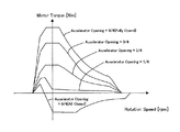
- FIG. 3 is a diagram showing an example of an accelerator opening degree-torque table.
- FIG. 4 is a flowchart illustrating a torque correction process of the electric vehicle.
- FIG. 5 is a diagram showing the relationship between the motor rotation speed and the torque fluctuation amount.
- FIG. 6 is a time chart of the rear motor torque, the front motor torque, and the total torque when the switching control of the front inverter is switched from the off state to the on state and the torque control is performed without considering the occurrence of the torque step. be.
- FIG. 1 is a block diagram illustrating a basic configuration of an electric vehicle system to which the electric vehicle control method of the present embodiment is applied.
- FIG. 2 is a flowchart illustrating a main process of drive control of an electric vehicle.
- FIG. 7 shows the case where the switching control of the front inverter is switched from the off state to the on state, and the rear motor torque, the front motor torque, and the total torque when the torque control (No. 1) in consideration of the occurrence of the torque step is performed.
- FIG. 8 is a time chart of rear motor torque, front motor torque, and total torque when torque control (No. 2) is performed in consideration of the torque step generated when the switching control of the front inverter is switched from the off state to the on state.
- FIG. 9 is a time chart of rear motor torque, front motor torque, and total torque when torque control is performed without considering the torque step generated when the switching control of the front inverter is switched from the on state to the off state.
- FIG. 10 is a time chart of the rear motor torque, the front motor torque, and the total torque when the torque is controlled in consideration of the torque step generated when the switching control of the front inverter is switched from the on state to the off state.
- FIG. 1 is a block diagram illustrating a main configuration of an electric vehicle system 100 to which a control method (control system) for an electric vehicle according to the present embodiment is applied.
- the electric vehicle in the present embodiment is a vehicle having a drive motor 4 (electric motor) as a drive source of the vehicle and capable of traveling by the driving force of the drive motor 4, and is an electric vehicle or a hybrid vehicle. Is included.
- the electric vehicle system 100 of the present embodiment applied to an electric vehicle has two drive motors 4 (front drive motor 4f and rear drive motor 4r).
- front drive motor 4f and rear drive motor 4r two drive motors 4
- the electric vehicle system 100 includes a front drive system fds, a rear drive system rds, a battery 1, and a motor controller 2 (control unit).
- the front drive system fds is provided with various sensors and actuators for controlling the front drive motor 4f that drives the front drive wheels 9f (left front drive wheels 9fL, right front drive wheels 9fR).
- the rear drive system rds is provided with various sensors and actuators for controlling the rear drive motor 4r that drives the rear drive wheels 9r (left rear drive wheels 9rL, right rear drive wheels 9rR).
- the front drive system fds and the rear drive system rds are individually controlled by the motor controller 2, respectively.
- the battery 1 functions as a power source for supplying (discharging) drive power to the drive motor 4 (front drive motor 4f, rear drive motor 4r), respectively, while the drive motor 4 (front drive motor 4f, rear drive motor 4r). ), It is connected to the inverter 3 (front inverter 3f, rear inverter 3r) so that it can be charged by receiving the supply of regenerative power.
- the motor controller 2 is, for example, a computer composed of a central processing unit (CPU), a read-only memory (ROM), a random access memory (RAM), and an input / output interface (I / O interface).
- the motor controller 2 constitutes the control device for the electric vehicle of the present invention, and is a component including a program for executing the control method for the electric vehicle of the present invention.
- the motor controller 2 has an accelerator opening APO, a vehicle speed V, a rotor phase ⁇ of the drive motor 4 (front rotor phase ⁇ f, a rear rotor phase ⁇ r), and a current Im of the drive motor 4 (front motor current Imf, rear motor). Signals of various vehicle variables indicating the vehicle state of the current Imr) are input as digital signals. Further, a signal from the mode switch that determines the traveling mode of the vehicle is input to the motor controller 2 based on the operation of the driver.
- the driving modes include, for example, a 2WD mode in which only the rear drive motor 4r (or the front drive motor 4f) is driven, a 4WD mode in which the front drive motor 4f and the rear drive motor 4r are constantly driven, and a 2WD mode and a 4WD mode based on the vehicle state. There is a switching mode that controls switching between.
- the motor controller 2 generates a PWM signal for controlling each drive motor 4 based on the input signal. Further, a drive signal for each inverter 3 is generated according to each generated PWM signal.
- Each inverter 3 has two switching elements (for example, power semiconductor elements such as IGBTs and MOS-FETs) provided corresponding to each phase.
- each inverter 3 converts the direct current supplied from the battery 1 into an alternating current or reversely converts the direct current supplied from the battery 1 into each drive motor 4 by turning on / off the switching element in response to a command from the motor controller 2. Adjust the supplied current to the desired value.
- Each drive motor 4 is configured as a three-phase AC motor.
- Each drive motor 4 (front drive motor 4f, rear drive motor 4r) generates a driving force by an AC current supplied from each corresponding inverter 3 (front inverter 3f, rear inverter 3r), and corresponds to the driving force.
- Each drive wheel 9 (front drive wheel 9f, rear drive wheel 9r) via each speed reducer 5 (front speed reducer 5f, rear speed reducer 5r) and each drive shaft 8 (front drive shaft 8f, rear drive shaft 8r). ).
- the drive motor 4 recovers the kinetic energy of the vehicle as electric energy by generating regenerative electric power when the drive motor 4 is rotated by the drive wheels 9 while the vehicle is traveling.
- the inverter 3 converts the alternating current (regenerative power) generated during the regenerative operation into a direct current and supplies it to the battery 1.
- the inverter 3 is preferably configured to perform switching control with respect to the current flowing in the field winding of the rotor of the drive motor 4. For example, when switching is stopped with respect to the current flowing through the stator winding in a state where a current is passed through the field winding of the rotor of the drive motor 4, a negative torque is generated by the magnetic flux generated by the field winding.
- a negative torque is generated by the magnetic flux generated by the field winding.
- the rotation sensor 6 (front rotation sensor 6f, rear rotation sensor 6r), which is an angular speed detecting means (executs the angular speed detecting step), has a rotor phase ⁇ (front rotor phase ⁇ f , rear rotor phase ⁇ ) of the drive motor 4. r ) is detected and output to the motor controller 2.
- the rotation sensor 6 is composed of, for example, a resolver, an encoder, or the like.
- the current sensor 7 detects each of the three-phase alternating currents (iu, iv, iwa) flowing through each drive motor 4. Since the sum of the three-phase alternating currents (iu, iv, iw) is 0, the current sensor 7 may detect the current of any two phases, and the current of the remaining one phase may be obtained by calculation. In particular, the current sensor 7 is a current flowing to the front drive motor 4f 3-phase alternating current (iu f, iv f, iw f) three-phase alternating current is a current flowing to the rear drive motor 4r (iu r, iv r , Iw r ) is detected.
- FIG. 2 is a flowchart illustrating basic processing in the control device of the electric vehicle by the motor controller 2 of the present embodiment.
- the motor controller 2 is programmed to execute the processes related to steps S201 to S205 shown in FIG. 2 at predetermined calculation cycles.
- step S201 the motor controller 2 performs an input process for acquiring various parameters used for executing the processes after step S202 according to the following processes 1 to 3.
- the motor controller 2 has an accelerator opening APO (%), a rotor phase ⁇ [rad], and a three-phase alternating current (iu) flowing from the accelerator opening sensor and each sensor (not shown above) to the drive motor 4. , Iv, iwa) [A], and the DC voltage value Vdc [V] of the battery 1. Further, the motor controller 2 acquires a mode switch signal.
- the motor controller 2 acquires the previous value of the motor torque command value (front motor torque command value Tmf, rear motor torque command value Tmr) stored in the internal memory, which will be described later.
- the motor controller 2 has a motor electric angular velocity ⁇ e [rad / s], a motor rotation speed ⁇ m [rad / s], and a motor rotation speed N based on each parameter acquired in accordance with the above “1.”. Calculate m [rpm] and wheel speed ⁇ w [km / h].
- the motor rotation speed is a mechanical angular speed of the drive motor 4 by dividing the motor electric angular velocity omega e in pole pairs of the drive motor 4 omega m (front motor speed omega mf, rear motor speed omega mr) Is calculated.
- the relationship between the motor rotation speed ⁇ m and the rotation speed of the drive shaft 8 which is the drive shaft is appropriately determined according to the gear ratio of the speed reducer 5. That is, the motor rotation speed ⁇ m is a speed parameter that correlates with the rotation speed of the drive shaft 8.
- the motor controller 2 calculates the motor rotation speed N m (front motor rotation speed N mf , rear motor rotation speed N mr ) by multiplying the motor rotation speed ⁇ m by the unit conversion coefficient (60 / 2 ⁇ ).
- (Iv) Wheel speed ⁇ w First, the motor controller 2 multiplies the front motor rotation speed ⁇ mf by the tire driving radius R, and based on the value obtained by this multiplication and the gear ratio of the front reducer 5f, the left front drive wheel speed ⁇ wfL and the right front The drive wheel speed ⁇ wfR is calculated. Further, the motor controller 2 multiplies the rear motor rotation speed ⁇ mr by the tire driving radius R, and based on the value obtained by this multiplication and the gear ratio of the final gear of the rear reducer 5r, the left rear drive wheel speed ⁇ wrL. And the right rear drive wheel speed ⁇ wrR is calculated. Then, in the present embodiment, a unit conversion coefficient (3600/1000) is applied to each wheel speed ⁇ w thus obtained, and the unit [m / s] of the wheel speed ⁇ w is converted to [km / h]. ..
- the vehicle speed is acquired from a sensor such as GPS, or for example , among the above-mentioned rotation speeds ( ⁇ mf , ⁇ mr ), the one with the lower rotation speed is selected during acceleration and the one with the higher rotation speed is selected during deceleration. However, when traveling at almost constant speed, one of them is selected and calculated as described above based on the wheel speed.
- step S202 the motor controller 2 calculates the basic target torque required by the driver based on the vehicle information.
- the motor controller 2 refers to the accelerator opening-torque table, and is based on the accelerator opening APO and the rear motor rotation speed ⁇ mr (the front motor rotation speed ⁇ mf may be used) acquired in step S201.
- the first torque target value Tm1 is calculated.
- FIG. 3 shows an example of an accelerator opening-torque table referred to by the motor controller 2 of the present embodiment.
- the motor controller 2 calculates the front motor torque command value Tmf and the rear motor torque command value Tmr based on the first torque target value Tm1, for example, according to a predetermined front-rear motor torque distribution.
- the motor controller 2 has, for example, the front motor torque command value Tmf and the rear motor torque command value by multiplying the first torque target value Tm1 by the front-rear driving force distribution gains Kf (0 ⁇ Kf ⁇ 1) and 1-Kf, respectively. Find Tmr.
- step S203 the motor controller 2 executes the torque correction process.
- the details of the torque correction process will be described later.
- step S204 the motor controller 2 executes the current command value calculation process. Specifically, the motor controller 2 was acquired in step S202 (S203), the front motor torque command value Tmf, the rear motor torque command value Tmr, the front motor rotation speed ⁇ mf , the rear motor rotation speed ⁇ mr , and step S201. Based on the DC voltage value V dc , the dq axis current target value ( id * , i q * ) is calculated with reference to a predetermined table.
- the motor controller 2 dq axis current target value set in the front drive motor 4f (i d *, i q *) Front dq-axis current target value is the (i df *, i qf * ), rear drive dq-axis current target value set in the motor 4r (i d *, i q *) rear dq-axis current target value is (i dr *, i qr * ) is calculated.
- step S205 the motor controller 2 executes the current control calculation process. Specifically, the motor controller 2, first, the three-phase alternating current value acquired in step S201 (iu, iv, iw) and on the basis of the rotor phase alpha, calculates the dq-axis current value (i d, i q) do. Next, the motor controller 2, the dq-axis current value (i d, i q) and dq-axis current target value obtained in step S204 (i d *, i q *) and dq-axis voltage command value from the deviation of ( Calculate v d , v q ).
- the motor controller 2 is set in the front dq-axis voltage command value (v df , v qf ), which is the dq-axis voltage command value (v d , v q ) set in the front drive motor 4f, and in the rear drive motor 4r.
- the motor controller 2 calculates the three-phase AC voltage command value (vu, vv, vw) based on the dq axis voltage command value (v d , v q) and the rotor phase ⁇ .
- the motor controller 2 the three-phase AC voltage command value set in the front drive motor 4f (vu, vv, vw) front three-phase AC voltage command value is a (vu f, vv f, vw f), rear three-phase AC voltage command value to be set to the drive motor 4r is calculated (vu, vv, vw) rear three-phase AC voltage command value is (vu f, vv f, vw f) a.
- the motor controller 2 obtains a PWM signal (tu, tv, tw) [%] based on the calculated three-phase AC voltage command value (vu, vv, vw) and the DC voltage value Vdc.
- a PWM signal (tu, tv, tw) [%] based on the calculated three-phase AC voltage command value (vu, vv, vw) and the DC voltage value Vdc.
- the electric vehicle system 100 of the present embodiment has a switching mode in which switching control is performed between the 2WD mode and the 4WD mode based on the vehicle state.
- a scene for performing switching control for example, there is a scene in which the 2WD mode is switched to the 4WD mode when the total torque T exceeds a predetermined value, and the 4WD mode is switched to the 2WD mode when the total torque T is equal to or less than the predetermined value.
- the difference between the vehicle speed and the vehicle speed V estimated from the rear drive motor 4r exceeds a predetermined value, or the rear corresponding to the previous value of the rear motor rotation speed ⁇ mr and the rear motor torque command value Tmr.
- the 2WD mode is switched to the 4WD mode in order to avoid slipping, and when the difference becomes less than the predetermined value, the 4WD mode is switched to the 2WD mode. ..
- the front inverter 3f of the present embodiment performs switching control with respect to the current flowing through the field winding provided in the rotor of the front drive motor 4f.
- the front inverter 3f switches the switching control to the off state when the front drive motor 4f is not driven. Then, the rotor of the front drive motor 4f switches from the state of being driven by itself to the state of being driven by the drive of the rear drive motor 4r and rotating. Further, the front inverter 3f switches the switching control to the ON state when driving the front drive motor 4f. Then, the rotor of the front drive motor 4f switches from the driven state of being driven by the drive of the rear drive motor 4r to the driven state of being driven by itself.
- the torque step is the current responsiveness of the front drive motor 4f and the rear drive motor 4r and the mechanical inertia (mechanical responsiveness) regardless of the magnitudes of the front motor torque command value Tmf and the front motor torque Tf. ), which corresponds to ⁇ T shown in FIG. 4 described later.
- the torque fluctuation amount corresponding to this torque step is calculated and reflected in the rear motor torque command value Tmr of the rear drive motor 4r to reduce or eliminate the torque step. Take control.
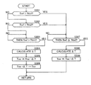
- FIG. 4 is a flowchart illustrating a torque correction process of the electric vehicle.
- FIG. 5 is a diagram showing the relationship between the motor rotation speed and the torque fluctuation amount. In the present embodiment, the steps from step S301 to step S309 shown below are executed in a predetermined cycle.
- step S301 the motor controller 2 determines whether or not the front motor torque command value Tmf is larger than the first threshold value Tth1, and if YES, determines that the switching control of the front inverter 3f is in the ON state.
- the process proceeds to S307, and if NO, the process proceeds to step S302.
- the first threshold value Tth1 is an index for determining whether or not the front inverter 3f has shifted from the off state to the on state for switching control, and is, for example, an arbitrary larger than 0 [Nm] or 0 [Nm]. Can be set to the value of.
- step S302 the motor controller 2 determines whether or not the front motor torque command value Tmf is larger than the second threshold value. If YES, the process proceeds to step S307. If NO, the switching control of the front inverter 3f is turned off. It is determined that the state is in the state, and the process proceeds to step S303.
- the second threshold value Tth2 is an index for determining whether or not the front inverter 3f has shifted from the on state to the off state for switching control, and is, for example, an arbitrary larger than 0 [Nm] or 0 [Nm]. Can be set to the value of.
- step S303 after step S302, the motor controller 2 determines whether or not the front motor torque command value Tmf is larger than the first threshold value Tth1, and if YES, the switching control of the front inverter 3f is turned on. It is determined that the result has been reached, and the process proceeds to step S304. If NO, step S303 is maintained.
- step S304 the motor controller 2 cancels out the torque step generated in a short time from when the front motor torque command value Tmf becomes larger than the first threshold value until the front motor torque Tf of the front drive motor 4f becomes zero.
- the torque fluctuation amount ⁇ T for this is calculated.
- the torque fluctuation amount ⁇ T is calculated as the difference between the characteristic line Tf1 and the characteristic line Tf2 using the rotation speed of the front drive motor 4f as an input value using the map shown in FIG.
- the characteristic line Tf1 is treated as the front motor torque Tf when the front drive motor 4f switches from the driven state to the drive state, that is, when the front motor torque command value Tmf becomes larger than the first threshold value Tth1 (for example, 0).
- the torque change amount is set so that the torque step can be offset while considering the current responsiveness of the front drive motor 4f and the rear drive motor 4r and the mechanical inertia (mechanical responsiveness). For example, if the front drive motor 4f and the rear drive motor 4r have the same current responsiveness and mechanical inertia (mechanical responsiveness), the magnitude of the torque change amount is set to the same magnitude as the torque step. Therefore, the torque step can be offset.
- step S305 the motor controller 2 corrects the value of the rear motor torque command value Tmr from [Tmr] to [Tmr- ⁇ T]. As a result, the value of the rear motor torque command value Tmr momentarily changes from [Tmr] to [Tmr- ⁇ T].
- step S306 the motor controller 2 changes the value of the rear motor torque command value Tmr from [Tmr- ⁇ T] to [Tmr] (value before correction) at a speed that can be followed by, for example, the rear motor torque Tr of the rear drive motor 4r. Increase monotonously.
- step S307 the motor controller 2 determines whether or not the front motor torque command value Tmf is equal to or less than the second threshold value after step S301 or step S302, and if YES, the switching control of the front inverter 3f is in the off state. It is determined that the result has been reached, and the process proceeds to step S308. If NO, step S307 is maintained.
- step S308 the motor controller 2 receives the front drive motor 4f from the time when the front drive motor 4f shifts from the drive state to the driven state, that is, when the front motor torque command value Tmf reaches the second threshold value Tth2 (for example, zero).
- Tth2 for example, zero
- the torque fluctuation amount ⁇ T for canceling the torque step generated in a short time until the front motor torque Tf reaches the torque value in the driven state is calculated.
- the torque fluctuation amount ⁇ T is calculated as the difference between the characteristic line Tf1 and the characteristic line Tf2 by using the map shown in FIG. 5 as the input value and using the rotation speed of the front drive motor 4f in the same manner as described above.
- the characteristic line Tf1 is the front motor torque Tf when the torque step is completed and the front drive motor 4f is completely driven
- step S309 the motor controller 2 corrects the value of the rear motor torque command value Tmr from [Tmr] to [Tmr + ⁇ T]. As a result, the value of the rear motor torque command value Tmr momentarily changes from [Tmr] to [Tmr + ⁇ T].
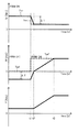
- FIG. 6 shows a case where the switching control of the front inverter 3f is switched from the off state to the on state, and the rear motor torque Tr, the front motor torque Tf, and the total torque T when the torque control is performed without considering the occurrence of the torque step. It is a time chart of.
- FIG. 7 shows the rear motor torque Tr and the front motor torque Tf when the switching control of the front inverter 3f is switched from the off state to the on state and the torque control (No. 1) in consideration of the occurrence of the torque step is performed. , It is a time chart of the total torque T.
- FIG. 8 shows the rear motor torque Tr, the front motor torque Tf, and the total torque when torque control (No. 2) is performed in consideration of the torque step generated when the switching control of the front inverter 3f is switched from the off state to the on state. It is a time chart of T.
- FIGS. 6-8 show a time chart when the front drive motor 4f switches from the driven state to the driven state while the rear drive motor 4r is being driven.
- the front motor torque Tf changes according to the front motor torque command value Tmf
- the rear motor torque Tr changes according to the rear motor torque command value Tmr.
- the total torque T is the sum of the front motor torque Tf and the rear motor torque Tr.
- the rear motor torque command value Tmr maintains a constant value, and thereby the rear motor torque Tr also maintains a constant value.
- the front motor torque command value Tmf is maintained at zero until time t1.
- the front inverter 3f is in the switching control off state (PWM OFF), and the front drive motor 4f is in the driven state, and a negative torque lower than 0 by ⁇ T is applied to the drive system.
- the front motor torque Tf rises with a predetermined inclination based on the value [Tmf (t1)] of the front motor torque command value Tmf, and the front motor torque Tf is indicated by the front motor torque command value Tmf at time t3. It converges to the value [Tmf (t1)].
- the total torque T increases with the increase of the front motor torque Tf from time t2 to t3.
- the rear motor torque command value Tmr maintains a constant value, and thereby the rear motor torque Tr also maintains a constant value. Therefore, from time t1 to time t2, the torque step generated by the front drive motor 4f is directly reflected in the total torque T, which gives an unpleasant torque shock to the driver.
- the torque step generated by the front drive motor 4f is the torque fluctuation amount generated by the corrected rear motor torque command value Tmr ([Tmr (t1)]) input to the rear inverter 3r. It is possible to eliminate the torque step generated by the total torque T and maintain a substantially constant value.
- the motor controller 2 After time t2, the motor controller 2 gradually raises the value of the rear motor torque command value Tmr from [Tmr (t1)] to [Tmr (t1) + ⁇ T] (FIG. 4, step S306), and the rear is reared.
- the motor torque Tr is gradually increased.
- the total torque T also gradually increases and converges to the total value of [Tmr (t1) + ⁇ T] and [Tmf (t1)] near time t3.
- the time chart of FIG. 8 is the same as the time chart of FIG. 7, but represents a case where step S306 of FIG. 4 is not executed. From FIGS. 7 and 8, in the present embodiment, by executing at least step S303, step S304, and step S305, it is possible to eliminate the torque step generated when the front drive motor 4f switches from the driven state to the driven state. You can see that.
- FIG. 9 is a time chart of the rear motor torque Tr, the front motor torque Tf, and the total torque T when the torque control is performed without considering the torque step generated when the switching control of the front inverter 3f is switched from the on state to the off state. Is.
- FIG. 10 is a time chart of the rear motor torque Tr, the front motor torque Tf, and the total torque T when the torque control is performed in consideration of the torque step generated when the switching control of the front inverter 3f is switched from the on state to the off state. Is.
- FIGS. 9 and 10 show a time chart in which the drive state of the front drive motor 4f is switched to the driven state while the drive of the rear drive motor 4r is maintained.
- the rear motor torque command value Tmr maintains a constant value, and thereby the rear motor torque Tr also maintains a constant value.
- the front motor torque command value Tmf and the front motor torque Tf decrease monotonically before the time t1, but maintain values larger than zero.
- the front inverter 3f is in the switching control ON state (PWM ON) until before the time t1, and the front drive motor 4f is in the drive state, and a positive torque is applied to the drive system.
- the total torque T is affected by the front motor torque Tf and decreases monotonically until time t1.
- the switching control of the front inverter 3f is turned off (PWM OFF), and the front drive motor 4f is stopped driving and becomes a driven state.
- a negative torque is started to be applied to the drive system, and after time t2, the front motor torque Tf applies a negative torque that is ⁇ T lower than zero to the drive system. Therefore, between the time t1 and the time t2, the front drive motor 4f generates a torque step ( ⁇ T).
- the rear motor torque command value Tmr keeps a constant value between the time t1 and the time t2. Therefore, the total torque T sharply decreases due to the torque step between the time t1 and the time t2, which causes an unpleasant torque shock for the driver. Further, after the time t2, the value lower by ⁇ T than the value at the time t1 is maintained.
- the torque step generated by the front drive motor 4f is the torque fluctuation amount generated by the corrected rear motor torque command value Tmr ([Tmr (t1)]) input to the rear inverter 3r. It is possible to eliminate the torque step generated by the total torque T and maintain a substantially constant value.
- step S307 by executing at least step S307, step S308, and step S309, it is possible to eliminate the torque step generated when the front drive motor 4f switches from the drive state to the driven state. I understand.
- the first motor (rear drive motor 4r) and the second motor (front drive motor 4f) are used as traveling drive sources, and the first torque is applied to the first inverter (rear inverter 3r).
- the command value (rear motor torque command value Tmr) By transmitting the command value (rear motor torque command value Tmr), the first motor (rear drive motor 4r) is driven and controlled (switching control), and the second torque command value (front motor) is sent to the second inverter (front inverter 3f).
- the second motor (front drive motor 4f) is driven and controlled (switching control), and the second inverter (front inverter 3f) is the second motor (front inverter 3f) based on the required driving force.
- This is a control method for an electric vehicle that performs switching control for switching between an on state in which drive control (switching control) of the front drive motor 4f) is performed and an off state in which the drive control (switching control) is stopped.
- the amount of torque fluctuation (which cancels out the torque step) generated in the second motor (front drive motor 4f) during control is calculated based on the rotation speed of the second motor (front drive motor 4f), and is based on the torque fluctuation amount.
- the first torque command value (rear motor torque command value Tmr) is corrected.
- the torque step appearing in the response (total torque T) of the entire drive system at the time of switching control of the second inverter (front inverter 3f) is corrected by the torque fluctuation amount (torque step), and the first torque command value (rear). It can be offset by the motor torque command value Tmr). Therefore, it is possible to execute the drive control to the second motor (front drive motor 4f) and the control to stop the drive control without giving an unpleasant torque shock due to the torque step to the driver.
- the second motor front drive motor 4f
- the second inverter front inverter 3f
- the second inverter front inverter 3f
- the second torque command value front motor torque command value Tmf
- the second is When it becomes larger than one threshold (Tth1), the drive control (switching control) is switched to the on state, and when the second torque command value (front motor torque command value Tmf) becomes smaller than the second threshold (Tth2), the drive control (switching) is switched.
- the second torque command value front motor torque command value Tmf
- the torque fluctuation amount (torque step) is calculated when it becomes smaller than the second threshold value (Tth2).
- the motor controller 2 does not confirm the switching of the second inverter (front inverter 3f) to the on state or the off state, and the torque fluctuation amount (the torque fluctuation amount (rear inverter 3r) is controlled at the timing of the switching control.
- the torque step) can be calculated, and the error in the amount of torque fluctuation caused by the timing deviation can be reduced.
- the first torque command value (rear motor torque command value Tmr) is corrected based on the torque fluctuation amount.
- the torque step can be reliably canceled by the corrected first torque command value (rear motor torque command value Tmr) without shifting the timing.
- the first motor (rear drive motor 4r) and the second motor (front drive motor 4f) and the first motor (rear drive motor 4r), which are the traveling drive sources, are used.
- the first inverter (rear inverter 3r) 1 A control unit (motor controller 2) that transmits a torque command value (rear motor torque command value Tmr) and a second torque command value (front motor torque command value Tmf) to a second inverter (front inverter 3f).
- the second inverter performs drive control (switching control) of the second motor (rear drive motor 4r) based on the required driving force, and stops the drive control (switching control). It is a control method of an electric vehicle that performs switching control to switch between the off state and the off state, and the control unit (motor controller 2) is generated in the second motor (front drive motor 4f) at the time of switching control (torque step).
- the torque fluctuation amount is calculated based on the rotation speed of the second motor (front drive motor 4f), and the first torque command value (rear motor torque command value Tmr) is corrected based on the torque fluctuation amount. ..
- the torque step that appears in the response (total torque T) of the entire drive system during switching control of the second inverter (front inverter 3f) is corrected by the torque fluctuation amount (torque step), and the first torque command value (rear). It can be offset by the motor torque command value Tmr). Therefore, it is possible to execute the drive control to the second motor (front drive motor 4f) and the control to stop the drive control without giving an unpleasant torque shock due to the torque step to the driver.
- the second inverter (front inverter 3f) that drives and controls the second motor (front drive motor 4f) is in an on state of performing drive control (switching control) and stops the drive control (switching control).
- the switching control for switching between the off state and the off state is performed, the switching control may be performed by the first inverter (rear inverter 3r) that drives and controls the first motor (rear drive motor 4r).
- the drive control (switching control) of the second inverter (front inverter 3f) is always on during traveling, and the torque fluctuation amount (torque) generated in the first motor (rear drive motor 4r) by the switching control is described.
- the step) is calculated, and the second torque command value (front motor torque command value Tmf) is corrected based on the torque fluctuation amount.
Landscapes
- Engineering & Computer Science (AREA)
- Power Engineering (AREA)
- Transportation (AREA)
- Mechanical Engineering (AREA)
- Life Sciences & Earth Sciences (AREA)
- Sustainable Development (AREA)
- Sustainable Energy (AREA)
- Electric Propulsion And Braking For Vehicles (AREA)
Priority Applications (7)
| Application Number | Priority Date | Filing Date | Title |
|---|---|---|---|
| CN202080101562.9A CN115916576B (zh) | 2020-05-29 | 2020-05-29 | 电动汽车的控制方法、以及电动汽车的控制系统 |
| PCT/IB2020/000515 WO2021240193A1 (ja) | 2020-05-29 | 2020-05-29 | 電動車両の制御方法、及び電動車両の制御システム |
| BR112022023666A BR112022023666A2 (pt) | 2020-05-29 | 2020-05-29 | Método de controle de veículo elétrico e sistema de controle de veículo elétrico |
| MX2022014643A MX2022014643A (es) | 2020-05-29 | 2020-05-29 | Metodo de control de vehiculo electrico y sistema de control de vehiculo electrico. |
| JP2022526532A JP7357159B2 (ja) | 2020-05-29 | 2020-05-29 | 電動車両の制御方法、及び電動車両の制御システム |
| US17/927,960 US12275310B2 (en) | 2020-05-29 | 2020-05-29 | Electric vehicle control method and system for switching drive control on motors |
| EP20938230.8A EP4159524A4 (en) | 2020-05-29 | 2020-05-29 | ELECTRIC VEHICLE CONTROL METHOD AND ELECTRIC VEHICLE CONTROL SYSTEM |
Applications Claiming Priority (1)
| Application Number | Priority Date | Filing Date | Title |
|---|---|---|---|
| PCT/IB2020/000515 WO2021240193A1 (ja) | 2020-05-29 | 2020-05-29 | 電動車両の制御方法、及び電動車両の制御システム |
Publications (1)
| Publication Number | Publication Date |
|---|---|
| WO2021240193A1 true WO2021240193A1 (ja) | 2021-12-02 |
Family
ID=78723016
Family Applications (1)
| Application Number | Title | Priority Date | Filing Date |
|---|---|---|---|
| PCT/IB2020/000515 Ceased WO2021240193A1 (ja) | 2020-05-29 | 2020-05-29 | 電動車両の制御方法、及び電動車両の制御システム |
Country Status (7)
| Country | Link |
|---|---|
| US (1) | US12275310B2 (https=) |
| EP (1) | EP4159524A4 (https=) |
| JP (1) | JP7357159B2 (https=) |
| CN (1) | CN115916576B (https=) |
| BR (1) | BR112022023666A2 (https=) |
| MX (1) | MX2022014643A (https=) |
| WO (1) | WO2021240193A1 (https=) |
Families Citing this family (2)
| Publication number | Priority date | Publication date | Assignee | Title |
|---|---|---|---|---|
| DE112022007138T5 (de) * | 2022-04-26 | 2025-02-27 | Gkn Automotive Limited | Antriebssystem |
| CN117533292B (zh) * | 2023-09-11 | 2024-07-16 | 比亚迪股份有限公司 | 车辆控制系统、控制方法、控制器及车辆 |
Citations (6)
| Publication number | Priority date | Publication date | Assignee | Title |
|---|---|---|---|---|
| JP2002019482A (ja) * | 2000-07-06 | 2002-01-23 | Toyota Motor Corp | 前後輪駆動車両の制御装置 |
| JP2002227679A (ja) * | 2001-02-02 | 2002-08-14 | Nissan Motor Co Ltd | ハイブリッド式車両制御装置 |
| JP2011231854A (ja) * | 2010-04-27 | 2011-11-17 | Toyota Motor Corp | 車両の制御装置 |
| JP2015080350A (ja) * | 2013-10-17 | 2015-04-23 | トヨタ自動車株式会社 | 電動車両 |
| JP2016210359A (ja) * | 2015-05-12 | 2016-12-15 | トヨタ自動車株式会社 | 四輪駆動車両の制御装置 |
| JP6485202B2 (ja) | 2015-05-12 | 2019-03-20 | トヨタ自動車株式会社 | 車両用駆動装置 |
Family Cites Families (3)
| Publication number | Priority date | Publication date | Assignee | Title |
|---|---|---|---|---|
| JP3915809B2 (ja) * | 2004-09-21 | 2007-05-16 | トヨタ自動車株式会社 | リーンリミットを低電力消費にて達成するハイブリッド車 |
| US9242642B2 (en) | 2011-10-27 | 2016-01-26 | Toyota Jidosha Kabushiki Kaisha | Electrically-powered vehicle and method of controlling the same |
| JP6443253B2 (ja) * | 2015-07-24 | 2018-12-26 | 株式会社デンソー | 電力変換器制御装置 |
-
2020
- 2020-05-29 MX MX2022014643A patent/MX2022014643A/es unknown
- 2020-05-29 WO PCT/IB2020/000515 patent/WO2021240193A1/ja not_active Ceased
- 2020-05-29 JP JP2022526532A patent/JP7357159B2/ja active Active
- 2020-05-29 EP EP20938230.8A patent/EP4159524A4/en active Pending
- 2020-05-29 US US17/927,960 patent/US12275310B2/en active Active
- 2020-05-29 BR BR112022023666A patent/BR112022023666A2/pt not_active Application Discontinuation
- 2020-05-29 CN CN202080101562.9A patent/CN115916576B/zh active Active
Patent Citations (6)
| Publication number | Priority date | Publication date | Assignee | Title |
|---|---|---|---|---|
| JP2002019482A (ja) * | 2000-07-06 | 2002-01-23 | Toyota Motor Corp | 前後輪駆動車両の制御装置 |
| JP2002227679A (ja) * | 2001-02-02 | 2002-08-14 | Nissan Motor Co Ltd | ハイブリッド式車両制御装置 |
| JP2011231854A (ja) * | 2010-04-27 | 2011-11-17 | Toyota Motor Corp | 車両の制御装置 |
| JP2015080350A (ja) * | 2013-10-17 | 2015-04-23 | トヨタ自動車株式会社 | 電動車両 |
| JP2016210359A (ja) * | 2015-05-12 | 2016-12-15 | トヨタ自動車株式会社 | 四輪駆動車両の制御装置 |
| JP6485202B2 (ja) | 2015-05-12 | 2019-03-20 | トヨタ自動車株式会社 | 車両用駆動装置 |
Also Published As
| Publication number | Publication date |
|---|---|
| MX2022014643A (es) | 2022-12-13 |
| US20230241982A1 (en) | 2023-08-03 |
| EP4159524A4 (en) | 2023-07-19 |
| BR112022023666A2 (pt) | 2022-12-20 |
| EP4159524A1 (en) | 2023-04-05 |
| US12275310B2 (en) | 2025-04-15 |
| CN115916576A (zh) | 2023-04-04 |
| JPWO2021240193A1 (https=) | 2021-12-02 |
| CN115916576B (zh) | 2025-08-22 |
| JP7357159B2 (ja) | 2023-10-05 |
Similar Documents
| Publication | Publication Date | Title |
|---|---|---|
| JP7435818B2 (ja) | 電動車両の制御方法、及び電動車両の制御システム | |
| EP3575129B1 (en) | Method for controlling electrically driven vehicle and device for controlling electrically driven vehicle | |
| US9440540B2 (en) | Electric vehicle and control method | |
| JP2003061203A (ja) | 電動車両駆動制御装置、電動車両駆動制御方法及びそのプログラム | |
| JP7211539B2 (ja) | 電動四輪駆動車両の制御方法及び電動四輪駆動車両の制御装置 | |
| WO2007049810A1 (ja) | モータ駆動システム | |
| JP2003254110A (ja) | ハイブリッド型車両駆動制御装置、ハイブリッド型車両駆動制御方法及びそのプログラム | |
| CN108667368B (zh) | 车辆及其控制方法 | |
| CN115243924B (zh) | 电动车辆的控制方法及电动车辆的控制装置 | |
| JP2003199207A (ja) | 電動車両駆動制御装置、電動車両駆動制御方法及びそのプログラム | |
| JP2013126366A (ja) | 車両 | |
| JP7357159B2 (ja) | 電動車両の制御方法、及び電動車両の制御システム | |
| JP4924073B2 (ja) | モータ制御装置及び車両の駆動力制御装置 | |
| JP2021022961A (ja) | 電動車両の制御方法および電動車両の制御装置 | |
| JP2017123759A (ja) | 車両 | |
| JP2009219189A (ja) | 四輪駆動車両 | |
| WO2022074717A1 (ja) | 電動四輪駆動車両の制御方法及び制御装置 | |
| JP2020205682A (ja) | 電動車両の制御方法、及び、制御装置 | |
| JP2013251988A (ja) | モータジェネレータ制御装置 | |
| WO2013157318A1 (ja) | 電動車両の制振制御装置および電動車両の制振制御方法 | |
| JP3692796B2 (ja) | ハイブリッド車両 | |
| CN116890617A (zh) | 电动车 | |
| JP2009214739A (ja) | 車両の駆動力制御装置 | |
| JP2010022179A (ja) | 車両およびその制御方法 | |
| JP4305409B2 (ja) | 車両用駆動制御装置 |
Legal Events
| Date | Code | Title | Description |
|---|---|---|---|
| 121 | Ep: the epo has been informed by wipo that ep was designated in this application |
Ref document number: 20938230 Country of ref document: EP Kind code of ref document: A1 |
|
| ENP | Entry into the national phase |
Ref document number: 2022526532 Country of ref document: JP Kind code of ref document: A |
|
| REG | Reference to national code |
Ref country code: BR Ref legal event code: B01A Ref document number: 112022023666 Country of ref document: BR |
|
| ENP | Entry into the national phase |
Ref document number: 112022023666 Country of ref document: BR Kind code of ref document: A2 Effective date: 20221121 |
|
| NENP | Non-entry into the national phase |
Ref country code: DE |
|
| ENP | Entry into the national phase |
Ref document number: 2020938230 Country of ref document: EP Effective date: 20230102 |
|
| WWG | Wipo information: grant in national office |
Ref document number: 17927960 Country of ref document: US |
|
| WWG | Wipo information: grant in national office |
Ref document number: 202080101562.9 Country of ref document: CN |