WO2021234874A1 - 医療用コイル、その製造方法、および医療機器 - Google Patents
医療用コイル、その製造方法、および医療機器 Download PDFInfo
- Publication number
- WO2021234874A1 WO2021234874A1 PCT/JP2020/020000 JP2020020000W WO2021234874A1 WO 2021234874 A1 WO2021234874 A1 WO 2021234874A1 JP 2020020000 W JP2020020000 W JP 2020020000W WO 2021234874 A1 WO2021234874 A1 WO 2021234874A1
- Authority
- WO
- WIPO (PCT)
- Prior art keywords
- coil
- metal
- round wire
- winding
- wire coil
- Prior art date
- Legal status (The legal status is an assumption and is not a legal conclusion. Google has not performed a legal analysis and makes no representation as to the accuracy of the status listed.)
- Ceased
Links
Images





Classifications
-
- A—HUMAN NECESSITIES
- A61—MEDICAL OR VETERINARY SCIENCE; HYGIENE
- A61B—DIAGNOSIS; SURGERY; IDENTIFICATION
- A61B17/00—Surgical instruments, devices or methods
- A61B17/00234—Surgical instruments, devices or methods for minimally invasive surgery
-
- A—HUMAN NECESSITIES
- A61—MEDICAL OR VETERINARY SCIENCE; HYGIENE
- A61B—DIAGNOSIS; SURGERY; IDENTIFICATION
- A61B17/00—Surgical instruments, devices or methods
- A61B17/28—Surgical forceps
- A61B17/29—Forceps for use in minimally invasive surgery
-
- A—HUMAN NECESSITIES
- A61—MEDICAL OR VETERINARY SCIENCE; HYGIENE
- A61B—DIAGNOSIS; SURGERY; IDENTIFICATION
- A61B17/00—Surgical instruments, devices or methods
- A61B17/00234—Surgical instruments, devices or methods for minimally invasive surgery
- A61B2017/00292—Surgical instruments, devices or methods for minimally invasive surgery mounted on or guided by flexible, e.g. catheter-like, means
- A61B2017/0034—Surgical instruments, devices or methods for minimally invasive surgery mounted on or guided by flexible, e.g. catheter-like, means adapted to be inserted through a working channel of an endoscope
-
- A—HUMAN NECESSITIES
- A61—MEDICAL OR VETERINARY SCIENCE; HYGIENE
- A61B—DIAGNOSIS; SURGERY; IDENTIFICATION
- A61B17/00—Surgical instruments, devices or methods
- A61B2017/00526—Methods of manufacturing
-
- A—HUMAN NECESSITIES
- A61—MEDICAL OR VETERINARY SCIENCE; HYGIENE
- A61B—DIAGNOSIS; SURGERY; IDENTIFICATION
- A61B17/00—Surgical instruments, devices or methods
- A61B2017/00681—Aspects not otherwise provided for
- A61B2017/00725—Calibration or performance testing
-
- A—HUMAN NECESSITIES
- A61—MEDICAL OR VETERINARY SCIENCE; HYGIENE
- A61B—DIAGNOSIS; SURGERY; IDENTIFICATION
- A61B17/00—Surgical instruments, devices or methods
- A61B17/28—Surgical forceps
- A61B17/29—Forceps for use in minimally invasive surgery
- A61B2017/2901—Details of shaft
- A61B2017/2905—Details of shaft flexible
-
- A—HUMAN NECESSITIES
- A61—MEDICAL OR VETERINARY SCIENCE; HYGIENE
- A61B—DIAGNOSIS; SURGERY; IDENTIFICATION
- A61B17/00—Surgical instruments, devices or methods
- A61B17/28—Surgical forceps
- A61B17/29—Forceps for use in minimally invasive surgery
- A61B2017/2926—Details of heads or jaws
- A61B2017/2932—Transmission of forces to jaw members
- A61B2017/2933—Transmission of forces to jaw members camming or guiding means
- A61B2017/2937—Transmission of forces to jaw members camming or guiding means with flexible part
Definitions
- the present invention relates to a medical coil, a method for manufacturing the same, and a medical device.
- Medical coils are used in medical devices such as treatment tools that are inserted into the treatment tool channel of an endoscope, for example.
- the medical coil is inserted through a curved treatment instrument channel.
- the medical coil is rotated within the curved treatment tool channel.
- Medical coils are required to have "rotational transmissibility" that transmits the rotation of the hand to the tip and "compression resistance” that can maintain the shape against compressive force.
- Patent Document 1 proposes a flexible sheath in which a tightly wound round wire coil having excellent rotational transmissibility is arranged outside a coarsely wound flat wire coil having excellent compression resistance.
- the present invention has been made in view of the above problems, and an object of the present invention is to provide a medical coil having excellent rotational transmissibility even if the outer diameter is small and a method for manufacturing the same. Further, an object of the present invention is to provide a medical device capable of reducing the diameter and improving operability by providing the medical coil.
- the medical coil according to the first aspect has a plurality of winding layers in which a metal wire is spirally wound, and the plurality of winding layers form a multilayer coil.
- the medical coil has an inner layer in the multi-layer coil made of a metal round wire and an outer layer in the multi-layer coil made of a flat metal wire.
- the method for manufacturing a medical coil according to the second aspect is a first step of winding a metal round wire around a core metal to form at least one layer of the round wire coil, and a metal on the outermost peripheral portion of the round wire coil. It has a second step of winding a flat wire to form a flat wire coil.
- the medical device according to the third aspect includes the medical coil of the first aspect.
- FIG. 1st Embodiment of this invention It is a schematic front view which shows the structural example of the medical device which concerns on 1st Embodiment of this invention. It is sectional drawing which follows the AA line in FIG. It is a schematic sectional drawing which shows the structural example of the medical coil which concerns on 1st Embodiment of this invention. It is a schematic diagram which shows the example of the 1st step of the manufacturing method of the medical coil which concerns on 1st Embodiment of this invention. It is a schematic diagram which shows the example of the 2nd step of the manufacturing method of the medical coil which concerns on 1st Embodiment of this invention. It is operation
- a preferable numerical range may be exemplified with respect to a dimensional value, for example, "X (lower limit value) or more, Y (upper limit value) or less".
- X lower limit value
- Y upper limit value
- a numerical range in which the combination of a lower limit value and an upper limit value is appropriately changed within the widest numerical range is also a preferable range unless otherwise specified.
- FIG. 1 is a schematic front view showing a configuration example of a medical device according to the first embodiment of the present invention.
- FIG. 2 is a cross-sectional view taken along the line AA in FIG.
- the grasping forceps 50 (medical device) shown in FIG. 1 is an example of the medical device of the first embodiment.
- the grasping forceps 50 can be inserted into the patient's body through the endoscopic treatment tool channel.
- the grasping forceps 50 has an operation portion 51 and an insertion portion 52 in this order from the proximal end to the distal end in the insertion direction.
- a long operation shaft 5 is inserted inside the operation portion 51 and the insertion portion 52.
- the operating shaft 5 transmits the linear motion of the operating portion 51 to the distal end of the inserting portion 52.
- the operation shaft 5 is a metal stranded wire or a single metal wire made of a material such as SUS304.
- the diameter of the operation shaft 5 may be 0.1 mm or more and 1.4 mm or less, and more preferably 0.3 mm or more and 0.8 mm or less.
- the operation unit 51 is arranged outside the endoscope and is operated by the operator.
- the operation unit 51 has a cylinder 51a, a guide member 51b, and a slider 51c.
- the cylinder 51a is formed in a cylindrical shape.
- An operation shaft 5 is inserted inside the cylinder 51a.
- a guide member 51b extends in the axial direction of the cylinder 51a at the proximal end (right end in the figure) of the cylinder 51a.
- the guide member 51b is a columnar shape that slidably supports the slider 51c.
- a guide hole 51d extending in the longitudinal direction of the slider 51c penetrates in the central portion of the slider 51c in the radial direction.
- a slider 51c is slidably fitted in the guide hole 51d.
- the slider 51c is fixed to the proximal end of the operating shaft 5 inserted into the cylinder 51a and the guide hole 51d.
- the slider 51c pulls the operation shaft 5 toward the proximal end side by moving toward the proximal end side along the guide member 51b.
- the slider 51c is provided with a stopper 51e that can be brought into contact with and detached from the guide member 51b. The stopper 51e fixes the slide position of the slider 51c when it comes into contact with the guide member 51b.
- the insertion portion 52 is a long member inserted into the treatment tool channel of the endoscope.
- the insertion section 52 has a length that allows it to be inserted into the patient's body through the opening at the distal end of the treatment instrument channel.
- the insertion portion 52 has a forceps portion 1, a coil sheath 10 (medical coil), and a proximal end sheath 52a in this order from the distal end to the proximal end.
- the coil sheath 10 is an example of the medical coil of the present embodiment.
- the forceps portion 1 has a main body portion 6, a grip portion 2, a slider 4, and a link 3.
- the main body 6 is made of a columnar hard member.
- a first grip 2a forming a part of the grip 2 described later is provided.
- a guide hole 6a for supporting the slider 4 described later so as to be slidable in the axial direction is formed.
- the distal end 10a of the coil sheath 10, which will be described later, is connected to the outer peripheral portion of the proximal end 6b of the main body 6.
- the grip portion 2 grips, for example, a living tissue.
- the grip portion 2 has a first grip 2a fixed to the distal end of the main body portion 6 and a second grip 2b provided so as to be detachable from the first grip 2a.
- the second grip 2b is a lever rotatably fixed to a rotation support shaft 6c arranged in the vicinity of the first grip 2a in the main body 6.
- the first end portion E1 of the second grip 2b can be brought into contact with and separated from the first grip 2a according to the rotation position.
- the distal end of the link 3 is connected to the second end E2 opposite to the first end E1 with the rotation support shaft 6c interposed therebetween.
- the proximal end of the link 3 is connected to the distal end of the slider 4, which will be described later, and converts the linear motion of the slider 4 into the rotation of the second grip 2b.
- the slider 4 is a shaft member that can slide along the longitudinal direction of the guide hole 6a of the main body 6.
- the proximal end of the link 3 is connected to the distal end of the slider 4.
- the distal end of the operating shaft 5 is connected to the proximal end of the slider 4.
- the coil sheath 10 of the present embodiment includes a multi-layer coil including a round wire coil 11 and a flat wire coil 12.
- the round wire coil 11 and the flat wire coil 12 form a plurality of winding layers in which a metal wire in the present embodiment is spirally wound.
- the round wire coil 11 is formed by spirally winding a metal round wire Wr, which is a metal strand.
- the metal round wire Wr is made of a metal such as stainless steel, and is a single wire having a substantially circular cross-sectional shape (hereinafter, simply referred to as a cross-sectional shape) orthogonal to the longitudinal direction.
- examples of the material of the metal round wire Wr include SUS304, SUS316, SUS631J1, and SUS301.
- the cross-sectional shape of the metal round wire Wr used for the round wire coil 11 is more preferably a perfect circle, but it does not have to be a strict perfect circle.
- the cross-sectional shape of the metal round wire Wr may be an approximate shape of a circle, an ellipse, an approximate shape of an ellipse, or the like.
- the cross-sectional shape of the metal round wire Wr is a non-round shape, it may be a non-round shape caused by a manufacturing error, or it may be a non-round shape intentionally processed.
- the ratio B / A represents the degree of non-roundness in the cross-sectional shape.
- the ratio B / A may be 1 or more and 1.1 or less, and more preferably 1 or more and 1.05 or less.
- the diameter of the metal round wire Wr means the average diameter.
- the diameter of the metal round wire Wr is preferably small from the viewpoint of reducing the diameter of the coil sheath 10 and improving the flexibility.
- the diameter of the metal round wire Wr is preferably large in order to increase the rigidity from the viewpoint of maintaining good rotational transmissibility and compression resistance.
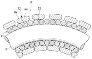
- FIG. 3 is a schematic cross-sectional view showing a configuration example of a medical coil according to the first embodiment of the present invention.
- d may be 0.1 mm or more and 0.3 mm or less, and more preferably 0.1 mm or more and 0.2 mm or less.
- FIG. 3 is an axial cross section including the central axis of the operation shaft 5, strictly speaking, the cross section shown in FIG. 3 is not a cross section orthogonal to the extending direction (winding direction) of each metal round wire Wr.
- the metal round wire Wr is a perfect circle, the shape of the axial cross section of the round wire coil 11 is elliptical, but in FIG.
- the diameter d of the metal circle line Wr shown in the figure indicates a dimensional value of a cross section orthogonal to the extending direction of the metal circle line Wr.
- the cross section of the flat wire coil 12 is similarly modeled, and w and t also indicate the dimensional values of the cross section orthogonal to the extending direction (winding direction) of the metal flat wire Wf, similarly to d.
- the round wire coil 11 is tightly wound.
- the round wire coil 11 is "tightly wound", it means that the metal round wires Wr adjacent to each other in the axial direction of the round wire coil 11 are in close contact with each other, or the surfaces of the metal round wires Wr adjacent to each other are close to each other. It means that the distance is 10% or less of the diameter of the metal round wire Wr.
- the size of the inner diameter of the round wire coil 11 in the coil sheath 10 is substantially equal to the diameter d5 of the operation shaft 5 through which the operation shaft 5 can be inserted.
- the operation shaft 5 can smoothly move in the axial direction inside the round wire coil 11.
- the inner diameter of the round wire coil 11 is D11
- (D11-d5) may be 0.01 mm or more and 0.4 mm or less, and more preferably 0.05 mm or more and 0.3 mm or less.
- the round wire coil 11 is formed by winding N round metal wires Wr (N is a natural number) in N rows.
- N may be 1 or more and 16 or less, and more preferably 4 or more and 8 or less.
- the winding direction of the round wire coil 11 may be S winding or Z winding. In the example shown in FIG. 2, the winding is S.
- the S winding is a winding method in which the inclination of the spiral is downward to the right when the coil is viewed in the radial direction from the outside with the axial direction of the coil aligned in the vertical direction.
- S winding can be said to be a winding method along the striation of the left-handed screw.
- the Z-winding is a winding method in which the inclination of the spiral rises to the right when the coil is viewed in the radial direction from the outside with the axial direction of the coil aligned in the vertical direction.
- Z winding can be said to be a winding method along the striation of a right-handed screw.
- the flat wire coil 12 is formed by spirally winding a metal flat wire Wf, which is a metal wire, around the outer peripheral portion of the round wire coil 11.
- the flat metal wire Wf is made of a metal such as stainless steel, and is a single wire having an aspect ratio of a cross-sectional shape orthogonal to the longitudinal direction (hereinafter, simply referred to as a cross-sectional shape) of more than 1.
- the aspect ratio of the metal flat line Wf is a ratio b / when the longitudinal direction and the lateral direction orthogonal to each other are specified in the cross-sectional shape, and the maximum length in the longitudinal direction is b and the maximum length in the lateral direction is a. Defined by a.
- the longitudinal direction and the lateral direction for determining the aspect ratio are specified so that the distance between the plane extending in the longitudinal direction and the surface of the cross-sectional shape of the metal flat line Wf in the lateral direction is minimized as a whole.
- the cross-sectional shape of the metal flat line Wf may be, for example, a rectangle, a rectangle with rounded four corners, an ellipse, an ellipse with both ends rounded in a semicircle, and similar shapes thereof.
- the cross-sectional shape of the metal flat wire Wf in the flat wire coil 12 shown in FIG. 3 is a rectangle with rounded four corners.
- the longitudinal direction of the cross-sectional shape of the metal flat line Wf is the long side direction, and the maximum length thereof is the width w in the long side direction.
- the short side direction is the short side direction, and the thickness t in the maximum long short side direction.
- the longitudinal direction is the major axis direction and the maximum length thereof is the major axis of the ellipse.
- the lateral direction is the minor axis direction, and its maximum length is the minor axis.
- the maximum length of the metal flat wire Wf in the longitudinal direction is referred to as width
- the maximum length in the lateral direction is referred to as thickness.
- the aspect ratio of the metal flat line Wf may be more than 1 and 3 or less, and more preferably 1.5 or more and 2.5 or less.
- the aspect ratio of the metal flat wire Wf used for the flat wire coil 12 is larger than the ratio B / A of the metal round wire Wr used for the round wire coil 11.
- the width w of the metal flat wire Wf used for the flat wire coil 12 may be 1 time or more and 3 times or less the diameter d of the metal round wire Wr, and more preferably 1 time or more and 2 times or less.
- w / d is less than 1, the metal flat wire Wf easily enters the V-shaped gap S1 formed on the surface of the metal round wire Wr adjacent to each other in the axial direction of the coil sheath 10. If w / d exceeds 3, the coil sheath 10 is less likely to bend, and the rotational transmissibility may decrease.
- w may be 0.1 mm or more and 0.7 mm or less, and more preferably 0.3 mm or more and 0.5 mm or less.
- the thickness t of the metal flat wire Wf used for the flat wire coil 12 may be 0.5 times or more and 3 times or less of the diameter d of the metal round wire Wr, and may be 0.8 times or more and 1.5 times or less. Is more preferable. If t / d is less than 0.5, the rigidity of the flat wire coil 12 in the radial direction is lowered, so that the compression resistance performance in the radial direction may be lowered. If t / d exceeds 3, the outer diameter of the coil sheath 10 may become too large, or the flexibility of the coil sheath 10 may decrease too much. For example, t may be 0.1 mm or more and 0.3 mm or less, and more preferably 0.1 mm or more and 0.2 mm or less.
- the same material as the metal round wire Wr used for the round wire coil 11 can be mentioned.
- the method for producing the metal flat wire Wf is not particularly limited.
- the metal flat wire Wf may be manufactured by rolling a metal round wire Wr.
- the flat wire coil 12 is tightly wound around the outer peripheral portion of the round wire coil 11 so that the metal flat wires are adjacent to each other in the width direction of the metal flat wires.
- the flat wire coil 12 is wound around the outer peripheral portion of the round wire coil 11 so as to be relatively movable at least in the axial direction of the round wire coil 11.
- the flat wire coil 12 is "tightly wound" it means that the metal flat wires adjacent to each other in the axial direction of the flat wire coil 12 are in close contact with each other, or the surfaces of the metal flat wires adjacent to each other in the width direction are close to each other. Means that the distance is less than or equal to 5% of the width of the metal flat line.
- the flat wire coil 12 may be formed by winding M (M is a natural number) metal flat wires in M rows.
- the flat wire coil 12 is wound so as to intersect the round wire coil 11 when viewed from the radial direction.
- the winding direction may be S winding or Z winding. It is more preferable that the winding direction of the flat wire coil 12 is opposite to the winding direction of the round wire coil 11. In this case, stable rotational transmissibility can be obtained regardless of the rotational direction of the coil sheath 10 as compared with the case where the winding directions are the same.
- the flat wire coil 12 has a Z winding opposite to the S winding, corresponding to the round wire coil 11 having an S winding.
- the winding directions of the round wire coil 11 and the flat wire coil 12 will be described as being opposite to each other.
- the coil sheath 10 is a multi-layer coil in which the flat wire coil 12 is wound around the outer peripheral portion of the round wire coil 11. Therefore, the round wire coil 11 and the flat wire coil 12 are laminated concentrically.
- the round wire coil 11 and the flat wire coil 12 form two winding layers in which a metal wire is spirally wound.
- the round wire coil 11 forms the inner layer Li in the multilayer coil.
- the inner peripheral portion of the round wire coil 11 forms the inner diameter portion of the coil sheath 10.
- the flat wire coil 12 forms the outer layer Lo in the multilayer coil.
- the outer peripheral portion of the flat wire coil 12 forms the outer diameter portion of the coil sheath 10.
- the outer diameter of the coil sheath 10 is ⁇ D11 + 2 ⁇ (d + t) ⁇ .
- the coil sheath 10 may include a layered portion (hereinafter, non-winding layer) that is not a winding layer.
- the outer diameter of the coil sheath 10 may be larger than ⁇ D11 + 2 ⁇ (d + t) ⁇ depending on the thickness of the non-winding layer.
- the non-winding layer provided on the outer peripheral portion of the winding layer is defined as the outer peripheral portion of the winding layer covered by the non-winding layer.
- the distal end 10a of the coil sheath 10 includes the distal end 11a of the round wire coil 11 and the distal end 12a of the flat wire coil 12.
- the distal ends 11a and 12a are located on the same plane orthogonal to the axial direction of the coil sheath 10.
- a step may be formed between the distal ends 11a and 12a.
- the distal end 10a is joined to the proximal end 6b of the body 6.
- the joining method is not particularly limited.
- the distal end 10a may be joined to the proximal end 6b by brazing, soldering, caulking, welding or the like.
- the proximal end side of the coil sheath 10 is inserted through the proximal end sheath 52a.
- the proximal sheath 52a is fixed to the distal end of the cylinder 51a.
- the base end sheath 52a forms an insertion passage that guides the coil sheath 10 from the mouthpiece portion toward the inside of the treatment tool channel when inserted into the mouthpiece portion.
- the proximal sheath 52a is a tubular member that can be inserted into the opening of the mouthpiece at the proximal end of the treatment tool channel.
- the proximal sheath 52a is made of a coil sheath that is shorter than the coil sheath 10 and harder than the coil sheath 10.
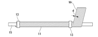
- FIG. 4 is a schematic diagram showing an example of the first step of the method for manufacturing a medical coil according to the first embodiment of the present invention.
- FIG. 5 is a schematic diagram showing an example of a second step of the method for manufacturing a medical coil according to the first embodiment of the present invention.
- the method for manufacturing a medical coil according to the present embodiment includes a first step and a second step.
- the metal round wire Wr is wound around the core metal 15 to form the round wire coil 11.
- the metal round wire Wr is not particularly limited as long as the above-mentioned round wire coil 11 can be formed by tightly winding the metal round wire Wr around the core metal 15.
- a metal wire having a substantially circular cross-sectional shape having a diameter d is used as the metal round wire Wr.
- the core metal 15 is a single wire longer than the coil sheath 10.
- the core metal 15 has a circular cross section having an outer diameter corresponding to the inner diameter D11 of the round wire coil 11.
- the material of the core metal 15 is not particularly limited as long as it can form a coil having an inner diameter D11 by winding a metal round wire Wr.
- copper may be used as the material of the core metal 15.
- the metal round wire Wr is tightly wound around the core metal 15 by a coil winding machine.
- the round wire coil 11 is formed on the core metal 15.
- the round wire coil 11 is formed longer than the total length of the coil sheath 10.
- eight metal round wires Wr are prepared and wound around the core metal 15 with eight threads.
- the winding direction of the metal round wire Wr is, for example, S winding. Both ends of the round wire coil 11 are fixed on the core metal 15 with crimp terminals 13.
- the metal round wire Wr that is not wound around the core metal 15 is cut at an appropriate portion. This completes the first step.
- the metal round wire Wr In the metal round wire Wr, the metal round wire Wr adjacent to each other is in line contact with each other. Compared to the metal flat wire, which may have surface contact or a gap that cannot be contacted, the metal round wire Wr is less likely to have uneven winding. Therefore, the metal round wire Wr tends to be tightly wound along the surface of the core metal 15.
- the envelope surface of the outer peripheral portion of the round wire coil 11 approaches a cylindrical surface similar to the cylindrical surface of the core metal 15.
- the metal flat wire Wf is wound around the outer peripheral portion of the round wire coil 11 to form the flat wire coil 12.
- the type of the metal flat wire Wf the above-mentioned appropriate type is used.
- the metal flat wire Wf a metal wire having a rectangular cross-sectional shape with rounded corners having a width w and a thickness t may be used.
- the flat metal wire Wf is tightly wound around the outer peripheral portion of the round wire coil 11 by a coil winding machine.
- two metal flat wires Wf adjacent to each other in the width direction are prepared and wound around the outer peripheral portion of the round wire coil 11 with two threads.
- the winding direction of the metal flat wire Wf is Z winding in the opposite direction corresponding to the S winding of the round wire coil 11.
- the flat wire coil 12 When the flat wire coil 12 is wound around the outer peripheral portion of the round wire coil 11, it is tightly wound adjacent to each other in the width direction, so that the inner surface of the flat wire coil 12 becomes a cylindrical surface. Since the metal round wire Wr of the round wire coil 11 that abuts on the inner surface of the flat wire coil 12 has a substantially circular cross-sectional shape, the contact portion with the inner surface of the flat wire coil 12 is a linear shape that extends spirally. When the metal round wire is wound around the outer peripheral portion of the round wire coil 11, the metal round wires abut in a dot shape at a position where the metal round wires intersect with each other.
- the reaction force from the round wire coil 11 acting on the flat wire coil 12 is dispersed as compared with the case where the metal round wire is wound, so that the deformation of the flat wire coil 12 at the time of winding is suppressed.
- the flat wire coil 12 is prevented from entering the gap S1 (see FIG. 3) on the surface of the round wire coil 11.
- the flat wire coil 12 is smoothly wound along the cylindrical surface which is the envelope surface of the outer circumference of the round wire coil 11.
- the width w of the metal flat wire Wf is made to be at least 1 times the diameter d of the metal round wire Wr so that the metal flat wire Wf enters the gap S1. That can be further suppressed.
- the width w of the metal flat wire Wf of the flat wire coil 12 is less than the diameter d of the metal round wire Wr, the metal flat wire Wf easily enters the gap S1 at the time of winding, although it is not as much as when the metal round wire is wound. Become.
- the winding direction of the metal flat wire Wf is disturbed by the influence of the winding direction of the metal round wire Wr, or unevenness is formed on the outer peripheral surface of the flat wire coil 12. do. If the winding direction of the flat wire coil 12 is disturbed, the tight winding property of the flat wire coil 12 is lowered, so that the flat wire coil 12 is easily compressed in the axial direction and the compression resistance in the axial direction is lowered. When the tight winding property is lowered, the portion of the round wire coil 11 that is not covered by the flat wire coil 12 increases, so that the resistance may be weakened against the compressive force acting in the radial direction from the outside of the coil sheath 10. When the width w of the metal flat wire Wf is equal to or larger than the diameter d of the metal round wire Wr, the above-mentioned problem is suppressed.
- both ends of the flat wire coil 12 are fixed on the round wire coil 11 by the crimp terminals 14.
- the metal flat wire Wf that is not wound around the round wire coil 11 is cut at an appropriate portion. This completes the second step.
- the round wire coil 11 and the flat wire coil 12 fixed to the core metal 15 are placed in a heat treatment furnace and heat-treated so that the core metal 15 is softened. After that, the softened core metal 15 is removed, and the round wire coil 11 and the flat wire coil 12 are cut to the length of the coil sheath 10 at both ends. With the above, the coil sheath 10 is manufactured. The coil sheath 10 is incorporated into the grasping forceps 50 by fixing both ends to the main body 6 and the cylinder 51a.
- the coil sheath 10 is used for the insertion portion 52 of the grasping forceps 50.
- An operation shaft 5 is inserted inside the coil sheath 10.
- the insertion section 52 is inserted into the patient's body, for example, via the endoscopic treatment tool channel.
- the insertion portion 52 is inserted into the curved treatment tool channel.
- the surgeon advances and retracts the insertion portion 52 in the longitudinal direction in the treatment instrument channel and rotates the insertion portion 52 in the treatment instrument channel in order to change the gripping direction of the forceps portion 1 as necessary for the treatment.
- the flat wire coil 12 forming the outermost layer of the insertion portion 52 receives an external force in the radial direction by sliding in the treatment tool channel.
- the coil sheath 10 receives an axially compressive force in the treatment tool channel according to the operation force of the operation unit 51, and is bent according to the curvature of the treatment tool channel. Further, the coil sheath 10 receives a compressive force in the radial direction from the contact portion with the treatment tool channel.
- the outermost layer of the coil sheath 10 is covered with a flat wire coil 12. Since the radial force from the outside is dispersed in the width direction of the flat wire coil 12, it is difficult to be transmitted to the inner round wire coil 11.
- the coil sheath 10 has a compressive resistance that resists a compressive force acting in the radial direction from the outside.
- the flat wire coil 12 is tightly wound around the outer peripheral portion of the tightly wound round wire coil 11 in a winding direction different from that of the round wire coil 11. As described in the manufacturing method, the flat wire coil 12 is smoothly wound along the envelope surface of the round wire coil 11, and unevenness and uneven winding on the outer peripheral surface are suppressed. Therefore, the moving of the treatment tool channel becomes smooth, and the compressive resistance in the axial direction is suppressed.
- FIG. 6 is an operation explanatory view of the medical coil according to the first embodiment of the present invention.
- the coil sheath 10 receives a compressive force on the inside of the bend (lower side in the figure) and a tensile force on the outside of the bend (upper side in the figure) along the bending line.
- the winding spacing of the round wire coil 11 and the flat wire coil 12 is widened. Since the winding interval of the flat wire coil 12 having a large radius of curvature of the curve is wider, the flat wire coil 12 moves relative to each other along the outer peripheral portion of the curved wire coil 11.
- each metal flat wire Wf of the flat wire coil 12 slides on a plurality of metal round wires Wr arranged at a pitch shorter than the winding pitch of the metal flat wire Wf, so that the metal flat wire Wf can move smoothly. Therefore, the resistance of the coil sheath 10 when curved is low.
- the width w of the metal flat wire Wf is 1 times or more the diameter d of the metal round wire Wr, even if the winding spacing of the metal round wire Wr is widened and a gap S2 penetrating in the radial direction is formed, even if the gap S2 is formed. It is possible to prevent the metal round wire Wr from entering the gap S2. Therefore, the resistance at the time of bending can be further suppressed.
- the width w of the metal flat wire Wf increases, the number of metal round wires Wr with which the metal flat wire Wf abuts increases. As a result, the metal flat wire Wf slides smoothly on the plurality of metal round wires Wr at the time of bending, and the resistance at the time of bending is further reduced.
- the coil sheath 10 is arranged within the curved treatment tool channel.
- the coil sheath 10 may be rotated in order to change the gripping direction of the forceps portion 1.
- the bending direction of the coil sheath 10 changes. If the resistance to bending is large, the amount of rotation at the bending portion decreases, so that the amount of rotation at the proximal end is less likely to be transmitted to the distal end. In the present embodiment, the resistance at the time of bending can be reduced, so that the rotational transmissibility of the coil sheath 10 is improved.
- FIG. 7 is a schematic cross-sectional view showing an example of a medical coil of a comparative example.
- FIG. 8 is an operation explanatory diagram of the medical coil of the comparative example.
- the coil sheath 110 of the comparative example is a multi-layer coil including a round wire coil 11 and a flat wire coil 12.
- the round wire coil 11 in the coil sheath 110 forms the outer layer of the coil sheath 110
- the flat wire coil 12 forms the inner layer of the coil sheath 110.
- the coil sheath 110 can be manufactured in the same manner as in the present embodiment except that the flat wire coil 12 is wound around the core metal 15 and then the round wire coil 11 is wound around the outer peripheral portion of the flat wire coil 12.
- the outer diameter of the coil sheath 110 becomes large.
- the cross-sectional shape of the metal flat line Wf rectangular can be covered with a good tightly wound winding layer having little change in the outer diameter without suppressing the outer diameter and impairing the bending performance.
- the coil sheath 110 when the coil sheath 110 is curved, the winding interval of the flat wire coil 12 on the outer side of the bending is widened, and a gap S4 in which the metal flat wire Wf is separated from each other in the width direction is formed.
- the gap S4 when the gap S4 is opened to be larger than the diameter of the metal round wire Wr, the metal round wire Wr easily enters the gap S4.
- the gap S4 cannot be reduced when it curves in the opposite direction, so that the resistance to bending increases. As the bending resistance increases, the rotational transmissibility of the coil sheath 110 decreases.
- the coil sheath 10 of the present embodiment even if the gap S2 of the inner round wire coil 11 is opened as much as the gap S4 at the time of bending, the metal flat wire Wf is wound on the outside. Therefore, the flat wire coil 12 is less likely to enter the gap S2 as compared with the case where the metal round wire Wr is wound as in the comparative example. As a result, the coil sheath 10 can be smoothly curved, and good rotational transmissibility can be obtained.
- the rotation transmissibility is excellent even if the outer diameter is small.
- the diameter of the insertion portion 52 can be reduced and the operability of the forceps portion 1 can be improved.
- FIG. 9 is a schematic cross-sectional view showing a configuration example of a medical coil according to a second embodiment of the present invention.
- a round wire coil 21 is added to the coil sheath 10 of the first embodiment.
- the coil sheath 20 can be used in place of the coil sheath 10 in the gripping forceps 50 of the first embodiment.
- the points different from the first embodiment will be mainly described.
- the round wire coil 21 is formed by spirally winding a metal round wire Wr around the outer peripheral portion of the round wire coil 11. However, the winding direction of the round wire coil 21 is different from the winding direction of the round wire coil 11. For example, when the round wire coil 11 is Z-wound, the round wire coil 21 is S-wound. The round wire coil 21 is tightly wound in the same manner as the round wire coil 11.
- the metal round wire Wr used for the round wire coil 21 may or may not be the same as the metal round wire Wr used for the round wire coil 11.
- the metal round wire Wr used for the round wire coil 21 may differ from the metal round wire Wr used for the round wire coil 11 in at least one of diameter, ratio B / A, number of rows, and material.
- the diameter of the round wire coil 21 may be larger than the diameter of the round wire coil 11. In this case, it becomes difficult for the round wire coil 21 to enter the gap S1 of the round wire coil 11, and it becomes easy to tightly wind the round wire coil 21. Further, at the time of bending, the inner round wire coil 11 is easily curved, and the size of the gap S2 due to the bending can be suppressed. For this reason, the round wire coil 21 tends to move outward along the outer peripheral portion of the round wire coil 11 at the time of bending, so that the resistance to bending is reduced.
- the flat wire coil 12 in the present embodiment is tightly wound around the outer peripheral portion of the round wire coil 21 in the winding direction opposite to that of the round wire coil 21.
- the flat wire coil 12 is Z-wound.
- the width, thickness, aspect ratio, number of rows, and material of the metal flat wire Wf used for the flat wire coil 12 are the diameter, ratio B / A, number of rows, and material of the metal round wire Wr used for the round wire coil 21. Accordingly, it can be determined in the same manner as in the first embodiment.
- the coil sheath 20 includes a first inner layer Li1 (inner layer) formed by the round wire coil 11, a second inner layer Li1 (inner layer) formed by the round wire coil 21, and an outer layer Lo formed by the flat wire coil 12. It is a multi-layer coil having.
- the coil sheath 20 is manufactured in the same manner as in the first embodiment except that the round wire coils 11 and 21 are formed into two layers in this order in the first step.
- the coil sheath 20 of the present embodiment is the same as the first embodiment because the round wire coils 11 and 21 are arranged in the inner layer of the multilayer coil and the flat wire coil 12 is arranged in the outer layer as in the first embodiment. Excellent rotation transmission even with a small outer diameter.
- the inner layer of the multilayer coil is composed of two layers of round wire coils 11 and 21 having different winding directions. Since the round wire coils 11 and 21 are in point-like contact at the intersection of the metal round wires Wr, the resistance at the time of bending is reduced as compared with the contact state between the metal round wire and the metal flat wire. As a result of reducing the bending resistance in the inner layer in this way, the bending resistance of the multi-layer coil as a whole is also reduced.
- the inner layer composed of the metal round wire is described as an example of one layer or two layers.
- the inner layer may be one or more layers, and is not limited to one or two layers.
- the inner layer may be three or more layers.
- the outer layer composed of flat metal wires is not limited to one layer. There may be two or more outer layers.
- the inner layer that does not form the innermost layer is arranged radially inside the outer layer that does not form the outermost layer. That is, in the multilayer coil, the winding layer made of metal round wires is arranged radially inside the winding layer made of metal flat wires.
- Example 1 is an example corresponding to the coil sheath 10 of the first embodiment.
- the coil sheath 10 of Example 1 is a two-layer multilayer coil having an inner layer 1 and an outer layer corresponding to the round wire coil 11 and the flat wire coil 12.
- a metal round wire Wr made of SUS304WPB was used as the material of the inner layer 1.
- the diameter of the metal round wire Wr was ⁇ 0.18 mm.
- a metal flat wire Wf manufactured by SUS304WPB was used as the material of the outer layer.
- the cross-sectional shape of the metal flat wire Wf was a rectangular shape with rounded four corners, a width of 0.45 mm, and a thickness of 0.18 mm.
- the coil sheath 10 of this embodiment was manufactured by using the method for manufacturing a medical coil of the first embodiment.
- a round wire coil 11 was formed by tightly winding eight metal round wires Wr around a copper core metal 15 having a diameter of ⁇ 1.8.
- the winding direction was S winding. Both ends of the round wire coil 11 were fixed by crimp terminals 13.
- the flat wire coil 12 was formed by tightly winding two metal flat wire Wr around the outer peripheral portion of the round wire coil 11.
- the winding direction was Z winding. Both ends of the flat wire coil 12 were fixed by crimp terminals 14.
- the multilayer coil was introduced into a horizontal heat treatment furnace H-004-CSBCX (trade name; manufactured by Fuji Kagaku Kikai) in order to soften the core metal 15, and was heat-treated at 350 ° C. for 60 minutes.
- the round wire coil 11 and the flat wire coil 12 were cut to a length of 2000 mm. Both ends of the cut round wire coil 11 and flat wire coil 12 were brazed.
- the test sample S of the coil sheath 10 of Example 1 was manufactured.
- a test sample T similar to the test sample S was manufactured except that the length was 20 mm and both ends were fixed by crimp terminals U (see FIG. 11).
- Example 2 is an example corresponding to the coil sheath 10 of the first embodiment. As shown in [Table 1], the coil sheath 10 of the second embodiment is the same as the coil sheath 10 of the first embodiment except that the width of the metal flat wire Wt forming the flat wire coil 12 of the outer layer is 0.36 mm. Is. The test samples S and T were also produced in the coil sheath 10 of this example.
- Example 3 is an example corresponding to the coil sheath 20 of the second embodiment.
- the coil sheath 20 of Example 3 corresponds to the round wire coil 11, 21, and the flat wire coil 12, and has a three-layer multilayer coil having an inner layer 1, an inner layer 2, and an outer layer.
- the inner layer 1 is the same as the inner layer 1 of the first embodiment except that the inner layer 1 is formed by winding around a core metal having a diameter of 1.4 mm and the winding direction is Z winding.
- the inner layer 2 was formed in the same manner as the inner layer 1 except that two metal round wires Wr similar to those of the inner layer 1 were tightly wound around the outer peripheral portion of the round wire coil 11 by S winding.
- the outer layer was formed in the same manner as the outer layer of Example 1 except that the outer layer was tightly wound around the outer peripheral portion of the round wire coil 11 by S winding.
- the test samples S and T were also produced in the coil sheath 20 of this example.
- Comparative Example 1 is the same as that of Example 1 except that the outer layer of Example 1 is arranged in the inner layer and the inner layer of Example 1 is arranged in the outer layer.
- the test samples S and T were also produced in the coil sheath of this comparative example.
- FIG. 10 is a schematic diagram showing a rotation transmissibility test device.
- the test apparatus 70 has a sheath rotation unit 71, a rotation angle detection unit 72, and a sheath holder 73.
- the sheath rotating portion 71 grips the first end portion e1 of the test sample S and rotates the test sample S by a certain angle in the circumferential direction.
- the rotation angle detection unit 72 detects the rotation angle of the second end portion e2 on the side opposite to the first end portion e1 in the test sample S.
- An angle detection sensor was used for the rotation angle detection unit 72.
- the sheath holder 73 keeps the curved shape of the test sample S constant while the test sample S is rotated.
- the sheath holder 73 includes a flat plate-shaped base 73A and a guide portion 73B formed on the base 73A.
- the guide portion 73B is formed by a U-shaped groove in which the test sample S linearly extended from the sheath rotating portion 71 is rotated along a circle having a diameter D, rotated 360 degrees, and further bent 90 degrees. rice field.
- the size of D was set to 200 mm.
- the rotation transmissibility is expressed by the rotation angle of the second end portion e2 (described as "tip rotation angle" in ⁇ Table 2 ⁇ ) when the test sample S is rotated by 45 degrees at the first end portion e1.
- the unit of the tip rotation angle was degrees (described as deg in ⁇ Table 2 ⁇ ).
- Rotational transmissibility is better as it approaches 45 degrees. If the tip rotation angle is 0 degrees or more and less than 5 degrees, it is defective (not good, "B” in [Table 2]), and if it is 5 degrees or more and less than 10 degrees, it is good (good, "A” in [Table 2]). When the temperature was 10 degrees or more and 45 degrees or less, it was evaluated as very good (very good, "A +" in [Table 2]).
- FIG. 11 is a schematic diagram showing an example of a compression resistance test device.
- the compressibility of the coil sheaths of Examples 1 to 3 and Comparative Example 1 was evaluated using a test sample T having a total length of 20 mm in which both ends were fixed by crimp terminals U. Each crimp terminal U was provided within a range of 5 mm from the end face of the test sample T.
- the test device 60 has a pedestal 61, a guide pin 62, a pressing head 64, and a load cell 65.
- the test device 60 further includes a control unit (not shown) and a measurement value calculation device.
- the pedestal 61 is a disc-shaped member having high rigidity. In the thickness direction of the pedestal 61, a through hole 61a and a hole portion 61b are formed from the upper side to the lower side. The inner diameter of the through hole 61a is smaller than the inner diameter of the test sample T. The inner diameter of the hole 61b is larger than that of the through hole 61a.
- the guide pin 62 has a rod 62a and a pressure plate 62b.
- the rod 62a has an outer diameter that can be inserted inside the through hole 61a and the test sample T.
- the rod 62a is inserted into the through hole 61a from below and protrudes above the pedestal 61.
- the pressure plate 62b has an outer shape that can be inserted into the hole 61b and cannot be inserted into the through hole 61a, and is fixed to the lower end of the rod 62a. By pressing the upper end portion downward, the rod 62a can move on the pedestal 61 from a state in which it protrudes longer than the total length of the test sample T to a state in which it protrudes shorter than the total length of the test sample T. ..
- the pressing head 64 is connected to an elevating device (not shown) via a load cell 65.
- the pressing head 64 is arranged so as to be able to move up and down above the rod 62a.
- the pressing head 64 presses the upper end of the test sample T inserted through the rod 62a from above toward the pedestal 61.
- the pressing head 64 is provided with a hole for inserting the tip end portion of the rod 62a. Therefore, when pressing the test sample T, the pressing load is not transmitted to the rod 62a.
- the load cell 65 measures the load acting on the pressing head 64.
- the spring constant of the test sample T was measured by the test device 60 as follows.
- the test sample T was inserted into the rod 62a protruding from the pedestal 61, and the test sample T was placed on the pedestal 61. After that, as shown by the alternate long and short dash line, the pressing head 64 was lowered, and the test sample T arranged on the pedestal 61 was compressed in the axial direction.
- the magnitude of the load output from the load cell 65 was acquired at each lowering position of the pressing head 64.
- the test apparatus 60 calculated the spring constant of the test sample T at the time of compression from the relationship between the descending position and the magnitude of the load.
- the unit of the spring constant was kN / mm.
- the reason why the rotation transmission property of the second embodiment is superior to that of the first embodiment is that the width w of the flat wire coil 12 of the first embodiment is 2.5 times the diameter d of the round wire coil 11.
- w was twice d.
- the rotation transmissibility test a loop in which the test sample S rotates 360 degrees is drawn. Therefore, when the base end side is rotated, the bending amount and bending direction with respect to the test sample S change in the loop portion as the rotation amount increases. I will do it. Therefore, the more the test sample S can be curved with less resistance, the better the rotational transmissibility.
- the width w of the flat wire coil 12 is twice or less the diameter d of the round wire coil 11, it is considered that the rotation transmission property is improved because the flat wire coil 12 is easily curved.
- Example 3 was superior in rotational transmissibility to Examples 1 and 2 and the inner layer was a two-layer structure of round wire coils 11 and 21. It is thought that it was because it was. Since the round wire coils 11 and 21 having different winding directions are in point contact with each other, they can smoothly slide relative to each other when curved. This reduces the resistance during bending.
- the measured values of the spring constants of Examples 1 to 3 and Comparative Example 1 in the compressibility test were 1.69 kN / mm and 1.69 kN / mm, respectively, 2.28 kN. It was / mm and 0.85 kN / mm.
- the compressibility was determined to be good (A) in Examples 1 to 3 and defective (B) in Comparative Example 1.
- Comparative Example 1 is the same as Examples 1 and 2 in terms of cross-sectional area and material, so it is considered that the reason why the spring constant was low is that the tight winding property was inferior. That is, when the round wire coil 11 enters the gap on the flat wire coil 12, the winding directions become irregular and a gap is generated between the windings adjacent to each other. Since the lowering amount of the pressing head 64 includes the lowering amount for eliminating the gap between the windings, the spring constant is lowered. It is considered that the reason why the spring constant of Example 3 was larger than that of Examples 1 and 2 is that the cross-sectional area of the test sample T was larger in Example 3.
- a medical coil having excellent rotational transmissibility even if the outer diameter is small and a method for manufacturing the same, and a medical device capable of improving operability by providing the above-mentioned medical coil are provided. be able to.
Landscapes
- Health & Medical Sciences (AREA)
- Surgery (AREA)
- Life Sciences & Earth Sciences (AREA)
- Biomedical Technology (AREA)
- Nuclear Medicine, Radiotherapy & Molecular Imaging (AREA)
- Engineering & Computer Science (AREA)
- Heart & Thoracic Surgery (AREA)
- Medical Informatics (AREA)
- Molecular Biology (AREA)
- Animal Behavior & Ethology (AREA)
- General Health & Medical Sciences (AREA)
- Public Health (AREA)
- Veterinary Medicine (AREA)
- Ophthalmology & Optometry (AREA)
- Media Introduction/Drainage Providing Device (AREA)
Priority Applications (4)
| Application Number | Priority Date | Filing Date | Title |
|---|---|---|---|
| PCT/JP2020/020000 WO2021234874A1 (ja) | 2020-05-20 | 2020-05-20 | 医療用コイル、その製造方法、および医療機器 |
| JP2022524773A JPWO2021234874A1 (https=) | 2020-05-20 | 2020-05-20 | |
| CN202080078266.1A CN114667106A (zh) | 2020-05-20 | 2020-05-20 | 医疗用线圈、其制造方法以及医疗设备 |
| US17/957,126 US20230030901A1 (en) | 2020-05-20 | 2022-09-30 | Medical coil, method for manufacturing the same, and medical device |
Applications Claiming Priority (1)
| Application Number | Priority Date | Filing Date | Title |
|---|---|---|---|
| PCT/JP2020/020000 WO2021234874A1 (ja) | 2020-05-20 | 2020-05-20 | 医療用コイル、その製造方法、および医療機器 |
Related Child Applications (1)
| Application Number | Title | Priority Date | Filing Date |
|---|---|---|---|
| US17/957,126 Continuation US20230030901A1 (en) | 2020-05-20 | 2022-09-30 | Medical coil, method for manufacturing the same, and medical device |
Publications (1)
| Publication Number | Publication Date |
|---|---|
| WO2021234874A1 true WO2021234874A1 (ja) | 2021-11-25 |
Family
ID=78708287
Family Applications (1)
| Application Number | Title | Priority Date | Filing Date |
|---|---|---|---|
| PCT/JP2020/020000 Ceased WO2021234874A1 (ja) | 2020-05-20 | 2020-05-20 | 医療用コイル、その製造方法、および医療機器 |
Country Status (4)
| Country | Link |
|---|---|
| US (1) | US20230030901A1 (https=) |
| JP (1) | JPWO2021234874A1 (https=) |
| CN (1) | CN114667106A (https=) |
| WO (1) | WO2021234874A1 (https=) |
Cited By (1)
| Publication number | Priority date | Publication date | Assignee | Title |
|---|---|---|---|---|
| CN115889630A (zh) * | 2022-11-30 | 2023-04-04 | 江苏亚盛金属制品有限公司 | 一种提升医疗用钢丝绳切口平整度的方法 |
Families Citing this family (2)
| Publication number | Priority date | Publication date | Assignee | Title |
|---|---|---|---|---|
| USD1022196S1 (en) * | 2020-07-07 | 2024-04-09 | Olympus Corporation | Operating unit of treatment tool for endoscope |
| CN116525286B (zh) * | 2023-07-04 | 2023-09-19 | 通友微电(四川)有限公司 | 一种紧凑型绕线电感及其制备方法 |
Citations (3)
| Publication number | Priority date | Publication date | Assignee | Title |
|---|---|---|---|---|
| JP2007260248A (ja) * | 2006-03-29 | 2007-10-11 | Fujinon Corp | 内視鏡用処置具 |
| WO2011092937A1 (ja) * | 2010-01-29 | 2011-08-04 | オリンパスメディカルシステムズ株式会社 | 挿入機器、内視鏡 |
| JP2016016299A (ja) * | 2014-07-11 | 2016-02-01 | 朝日インテック株式会社 | コイル体、およびコイル体を備える医療器具 |
Family Cites Families (5)
| Publication number | Priority date | Publication date | Assignee | Title |
|---|---|---|---|---|
| US1228439A (en) * | 1914-01-30 | 1917-06-05 | Clarence F Hotchkiss | Flexible shaft. |
| US6685696B2 (en) * | 1987-09-30 | 2004-02-03 | Lake Region Manufacturing, Inc. | Hollow lumen cable apparatus |
| US5154705A (en) * | 1987-09-30 | 1992-10-13 | Lake Region Manufacturing Co., Inc. | Hollow lumen cable apparatus |
| US6210395B1 (en) * | 1987-09-30 | 2001-04-03 | Lake Region Mfg., Inc. | Hollow lumen cable apparatus |
| JP4414662B2 (ja) * | 2003-03-03 | 2010-02-10 | オリンパス株式会社 | 密巻コイル及びこの密巻コイルを用いた医療用処置具 |
-
2020
- 2020-05-20 WO PCT/JP2020/020000 patent/WO2021234874A1/ja not_active Ceased
- 2020-05-20 CN CN202080078266.1A patent/CN114667106A/zh active Pending
- 2020-05-20 JP JP2022524773A patent/JPWO2021234874A1/ja active Pending
-
2022
- 2022-09-30 US US17/957,126 patent/US20230030901A1/en not_active Abandoned
Patent Citations (3)
| Publication number | Priority date | Publication date | Assignee | Title |
|---|---|---|---|---|
| JP2007260248A (ja) * | 2006-03-29 | 2007-10-11 | Fujinon Corp | 内視鏡用処置具 |
| WO2011092937A1 (ja) * | 2010-01-29 | 2011-08-04 | オリンパスメディカルシステムズ株式会社 | 挿入機器、内視鏡 |
| JP2016016299A (ja) * | 2014-07-11 | 2016-02-01 | 朝日インテック株式会社 | コイル体、およびコイル体を備える医療器具 |
Cited By (1)
| Publication number | Priority date | Publication date | Assignee | Title |
|---|---|---|---|---|
| CN115889630A (zh) * | 2022-11-30 | 2023-04-04 | 江苏亚盛金属制品有限公司 | 一种提升医疗用钢丝绳切口平整度的方法 |
Also Published As
| Publication number | Publication date |
|---|---|
| JPWO2021234874A1 (https=) | 2021-11-25 |
| US20230030901A1 (en) | 2023-02-02 |
| CN114667106A (zh) | 2022-06-24 |
Similar Documents
| Publication | Publication Date | Title |
|---|---|---|
| US20230030901A1 (en) | Medical coil, method for manufacturing the same, and medical device | |
| JP4889062B2 (ja) | ガイドワイヤ | |
| US8608670B2 (en) | Guidewire | |
| CN102371023B (zh) | 导线 | |
| TWI458509B (zh) | 插入體內用導管 | |
| US10426505B2 (en) | Hollow stranded wire line for manipulation | |
| US10603471B2 (en) | Medical guide wire | |
| TWI450740B (zh) | 醫療用導管 | |
| JP5226906B1 (ja) | 医療用コイルおよびその製造方法、ならびに医療機器 | |
| US9492642B2 (en) | Guidewire | |
| EP3290580B1 (en) | Manipulation rope | |
| US12514601B2 (en) | Guide wire | |
| JP2016515009A (ja) | 可撓性の細長いトルク伝達部材を含む医学的デバイス | |
| CN102762158A (zh) | 内窥镜用处理器具 | |
| JP3132410U (ja) | 結石破砕装置 | |
| CN215386828U (zh) | 导管 | |
| JP2015070895A (ja) | シャフト及びそのシャフトを用いたガイドワイヤ | |
| JP2015070896A (ja) | シャフト及びそのシャフトを用いたガイドワイヤ | |
| JP2013247991A (ja) | 医療用ワイヤおよびその製造方法、ならびに医療器具 | |
| JP7693567B2 (ja) | コイル体 | |
| CN223716188U (zh) | 一种微导丝 | |
| JP6423374B2 (ja) | 操作用中空撚り線 | |
| CN114904120A (zh) | 导管及其制造方法 |
Legal Events
| Date | Code | Title | Description |
|---|---|---|---|
| 121 | Ep: the epo has been informed by wipo that ep was designated in this application |
Ref document number: 20936516 Country of ref document: EP Kind code of ref document: A1 |
|
| ENP | Entry into the national phase |
Ref document number: 2022524773 Country of ref document: JP Kind code of ref document: A |
|
| NENP | Non-entry into the national phase |
Ref country code: DE |
|
| 122 | Ep: pct application non-entry in european phase |
Ref document number: 20936516 Country of ref document: EP Kind code of ref document: A1 |