WO2021234836A1 - 車室内検知装置、および、車室内検知方法 - Google Patents
車室内検知装置、および、車室内検知方法 Download PDFInfo
- Publication number
- WO2021234836A1 WO2021234836A1 PCT/JP2020/019884 JP2020019884W WO2021234836A1 WO 2021234836 A1 WO2021234836 A1 WO 2021234836A1 JP 2020019884 W JP2020019884 W JP 2020019884W WO 2021234836 A1 WO2021234836 A1 WO 2021234836A1
- Authority
- WO
- WIPO (PCT)
- Prior art keywords
- seat occupant
- detection
- occupant
- unit
- front seat
- Prior art date
- Legal status (The legal status is an assumption and is not a legal conclusion. Google has not performed a legal analysis and makes no representation as to the accuracy of the status listed.)
- Ceased
Links
Images





Classifications
-
- B—PERFORMING OPERATIONS; TRANSPORTING
- B60—VEHICLES IN GENERAL
- B60R—VEHICLES, VEHICLE FITTINGS, OR VEHICLE PARTS, NOT OTHERWISE PROVIDED FOR
- B60R21/00—Arrangements or fittings on vehicles for protecting or preventing injuries to occupants or pedestrians in case of accidents or other traffic risks
- B60R21/01—Electrical circuits for triggering passive safety arrangements, e.g. airbags, safety belt tighteners, in case of vehicle accidents or impending vehicle accidents
- B60R21/015—Electrical circuits for triggering passive safety arrangements, e.g. airbags, safety belt tighteners, in case of vehicle accidents or impending vehicle accidents including means for detecting the presence or position of passengers, passenger seats or child seats, and the related safety parameters therefor, e.g. speed or timing of airbag inflation in relation to occupant position or seat belt use
- B60R21/01512—Passenger detection systems
- B60R21/0153—Passenger detection systems using field detection presence sensors
-
- B—PERFORMING OPERATIONS; TRANSPORTING
- B60—VEHICLES IN GENERAL
- B60W—CONJOINT CONTROL OF VEHICLE SUB-UNITS OF DIFFERENT TYPE OR DIFFERENT FUNCTION; CONTROL SYSTEMS SPECIALLY ADAPTED FOR HYBRID VEHICLES; ROAD VEHICLE DRIVE CONTROL SYSTEMS FOR PURPOSES NOT RELATED TO THE CONTROL OF A PARTICULAR SUB-UNIT
- B60W40/00—Estimation or calculation of non-directly measurable driving parameters for road vehicle drive control systems not related to the control of a particular sub unit, e.g. by using mathematical models
- B60W40/08—Estimation or calculation of non-directly measurable driving parameters for road vehicle drive control systems not related to the control of a particular sub unit, e.g. by using mathematical models related to drivers or passengers
-
- G—PHYSICS
- G06—COMPUTING OR CALCULATING; COUNTING
- G06V—IMAGE OR VIDEO RECOGNITION OR UNDERSTANDING
- G06V20/00—Scenes; Scene-specific elements
- G06V20/50—Context or environment of the image
- G06V20/59—Context or environment of the image inside of a vehicle, e.g. relating to seat occupancy, driver state or inner lighting conditions
- G06V20/593—Recognising seat occupancy
-
- B—PERFORMING OPERATIONS; TRANSPORTING
- B60—VEHICLES IN GENERAL
- B60W—CONJOINT CONTROL OF VEHICLE SUB-UNITS OF DIFFERENT TYPE OR DIFFERENT FUNCTION; CONTROL SYSTEMS SPECIALLY ADAPTED FOR HYBRID VEHICLES; ROAD VEHICLE DRIVE CONTROL SYSTEMS FOR PURPOSES NOT RELATED TO THE CONTROL OF A PARTICULAR SUB-UNIT
- B60W40/00—Estimation or calculation of non-directly measurable driving parameters for road vehicle drive control systems not related to the control of a particular sub unit, e.g. by using mathematical models
- B60W40/08—Estimation or calculation of non-directly measurable driving parameters for road vehicle drive control systems not related to the control of a particular sub unit, e.g. by using mathematical models related to drivers or passengers
- B60W2040/0881—Seat occupation; Driver or passenger presence
-
- B—PERFORMING OPERATIONS; TRANSPORTING
- B60—VEHICLES IN GENERAL
- B60W—CONJOINT CONTROL OF VEHICLE SUB-UNITS OF DIFFERENT TYPE OR DIFFERENT FUNCTION; CONTROL SYSTEMS SPECIALLY ADAPTED FOR HYBRID VEHICLES; ROAD VEHICLE DRIVE CONTROL SYSTEMS FOR PURPOSES NOT RELATED TO THE CONTROL OF A PARTICULAR SUB-UNIT
- B60W2420/00—Indexing codes relating to the type of sensors based on the principle of their operation
- B60W2420/40—Photo, light or radio wave sensitive means, e.g. infrared sensors
- B60W2420/403—Image sensing, e.g. optical camera
-
- B—PERFORMING OPERATIONS; TRANSPORTING
- B60—VEHICLES IN GENERAL
- B60W—CONJOINT CONTROL OF VEHICLE SUB-UNITS OF DIFFERENT TYPE OR DIFFERENT FUNCTION; CONTROL SYSTEMS SPECIALLY ADAPTED FOR HYBRID VEHICLES; ROAD VEHICLE DRIVE CONTROL SYSTEMS FOR PURPOSES NOT RELATED TO THE CONTROL OF A PARTICULAR SUB-UNIT
- B60W2420/00—Indexing codes relating to the type of sensors based on the principle of their operation
- B60W2420/40—Photo, light or radio wave sensitive means, e.g. infrared sensors
- B60W2420/408—Radar; Laser, e.g. lidar
-
- B—PERFORMING OPERATIONS; TRANSPORTING
- B60—VEHICLES IN GENERAL
- B60W—CONJOINT CONTROL OF VEHICLE SUB-UNITS OF DIFFERENT TYPE OR DIFFERENT FUNCTION; CONTROL SYSTEMS SPECIALLY ADAPTED FOR HYBRID VEHICLES; ROAD VEHICLE DRIVE CONTROL SYSTEMS FOR PURPOSES NOT RELATED TO THE CONTROL OF A PARTICULAR SUB-UNIT
- B60W2540/00—Input parameters relating to occupants
- B60W2540/227—Position in the vehicle
Definitions
- This disclosure relates to a vehicle interior detection device and a vehicle interior detection method.
- the radio wave sensor When the radio wave sensor is installed in the front seat as in the occupant state detection system disclosed in Patent Document 1, the rear seat occupant is affected by the vibration of the front seat or the seat back pocket installed in the front seat. It may not be detected. Therefore, a method of detecting a rear seat occupant by installing a radio wave sensor above the seat and transmitting radio waves from the installation position toward the rear seat is conceivable.
- the front seat occupant when the radio wave sensor is installed above the seat, the front seat occupant is erroneously detected as a rear seat occupant depending on the seated state of the occupant existing in the front seat (hereinafter referred to as "front seat occupant").
- front seat occupant The seated state of the front seat occupant is the posture or seating position of the front seat occupant.
- This disclosure is made to solve the above-mentioned problems, and aims to detect the rear seat occupants in consideration of the seated state of the front seat occupants.
- the vehicle interior detection device has a first data acquisition unit that acquires the first data acquired by the first sensor, and a second sensor that is installed above the seat in the vehicle interior. 2
- the front seat occupant position estimation unit that estimates the position of the front seat occupant and the front seat occupant position estimation unit estimate based on the second data acquisition unit that acquires the data and the first data acquired by the first data acquisition unit.
- the detection range determination unit that determines the detection range of the second sensor based on the position of the front seat occupant, the second data acquired by the second data acquisition unit, and the second sensor determined by the detection range determination unit. It is provided with a rear seat occupant detection unit that detects rear seat occupants based on the detection range.
- the vehicle interior detection device can detect the rear seat occupant in consideration of the seated state of the front seat occupant.
- FIG. 1A is a block diagram showing a configuration example of the vehicle interior detection device according to the first embodiment.
- FIG. 1B is a block diagram showing another configuration example of the vehicle interior detection device according to the first embodiment.
- FIG. 2A is a diagram showing an example of installing a camera in a vehicle in the first embodiment
- FIG. 2B is a diagram showing an example of installing a radar in a vehicle in the first embodiment.
- FIG. 3A is a diagram showing an example of an image of the imageable range of the camera in the first embodiment
- FIG. 3B is a diagram showing an example of an image of the detectable range of the radar in the first embodiment.
- 4A, 4B, and 4C are diagrams showing an example of the positional relationship between the front seat, the rear seat, and the divided area in the first embodiment.
- 5A, 5B, 5C, and 5D are diagrams showing an example of an image of the detection range determined by the detection range determination unit in the first embodiment. It is a figure which shows an example of the state in the vehicle interior when the detection range determination part determines that there is no detection range of a radar in Embodiment 1.
- FIG. It is a flowchart for demonstrating operation of the vehicle interior detection apparatus which concerns on Embodiment 1.
- 8A and 8B are diagrams showing an example of the hardware configuration of the vehicle interior detection device according to the first embodiment.
- FIG. 10A and 10B are diagrams for explaining an example of the radar installation position and an example of the radar detection range when the radar is installed at a place other than above the rear seats. It is a figure for demonstrating an example of the method of dividing a detectable range by a detection range determination part in Embodiment 1.
- FIG. 10A and 10B are diagrams for explaining an example of the radar installation position and an example of the radar detection range when the radar is installed at a place other than above the rear seats. It is a figure for demonstrating an example of the method of dividing a detectable range by a detection range determination part in Embodiment 1.
- FIG. 10A and 10B are diagrams for explaining an example of the radar installation position and an example of the radar detection range when the radar is installed at a place other than above the rear seats.
- FIG. 1A is a block diagram showing a configuration example of the vehicle interior detection device 10 according to the first embodiment.
- the vehicle interior detection device 10 is connected to the first sensor 1 and the second sensor 2.
- the first sensor 1, the second sensor 2, and the vehicle interior detection device 10 are mounted on the vehicle 30 (see FIG. 2).
- the first sensor 1 and the second sensor 2 are sensors capable of detecting an occupant in the vehicle, and are, for example, a camera or a radar.
- the radar uses a frequency band such as a microwave band or a millimeter wave in a high frequency band lower than the optical frequency domain.
- the vehicle interior detection device 10 detects an occupant existing in the vehicle interior based on the data output from the first sensor 1 and the second sensor 2.
- the vehicle interior detection device 10 can accurately detect the rear seat occupants by combining the first data and the second data.
- the vehicle interior detection device 10 is acquired by the second sensor 2 after considering the position of the front seat occupant estimated based on the first data acquired by the first sensor 1. Based on the second data, the rear seat occupants are detected.
- the occupant detection by the vehicle interior detection device 10 may be performed while the vehicle 30 is running, or may be performed after the vehicle 30 is stopped. Further, the timing at which the vehicle interior detection device 10 detects the occupant may be the moment when the vehicle 30 stops, or may be after a certain time has elapsed from the moment when the vehicle 30 stops.
- the stop of the vehicle 30 may be a temporary stop (that is, a stop) or a continuous stop (that is, parking).
- the vehicle interior detection device 10 may acquire information indicating whether or not the vehicle 30 has stopped, such as information on a shift lever or a parking brake, from the vehicle 30.
- the vehicle interior detection device 10 includes a first data acquisition unit 11, a second data acquisition unit 12, a seat information acquisition unit 13, an occupant detection unit 14, a detection range determination unit 15, and a sensor control unit 16.
- the occupant detection unit 14 includes a front seat occupant detection unit 141 and a rear seat occupant detection unit 142.
- the front seat occupant detection unit 141 includes a front seat occupant position estimation unit 1411.
- the first data acquisition unit 11 acquires the first data acquired by the first sensor 1.
- the first data acquisition unit 11 outputs the acquired first data to the front seat occupant detection unit 141 of the occupant detection unit 14.
- the second data acquisition unit 12 acquires the second data acquired by the second sensor 2.
- the second data acquisition unit 12 outputs the acquired second data to the rear seat occupant detection unit 142 of the occupant detection unit 14.
- the seat information acquisition unit 13 acquires information on seats in the vehicle interior (hereinafter referred to as "seat information").
- the seat information is, for example, information regarding the slide position in front of and behind the seat, the angle of the backrest of the seat, or the height of the seat surface.
- the seat information acquisition unit 13 acquires seat information from, for example, a seat control unit (not shown) provided in the vehicle 30. By driving, for example, a slide motor (not shown) or a reclining motor (not shown), the seat control unit controls the front and rear slide positions of the seat, the angle of the backrest of the seat, or the height of the seat surface. Control.
- the seat information acquisition unit 13 outputs the acquired seat information to the front seat occupant detection unit 141 of the occupant detection unit 14.
- the occupant detection unit 14 detects an occupant existing in the vehicle 30 based on the first data acquired by the first data acquisition unit 11 or the second data acquired by the second data acquisition unit 12.
- the front seat occupant detection unit 141 of the occupant detection unit 14 detects the front seat occupant of the vehicle 30 based on the first data acquired by the first data acquisition unit 11.
- the front seat occupant position estimation unit 1411 is based on the first data acquired by the first data acquisition unit 11 and the seat information acquired by the seat information acquisition unit 13. , Estimate the position of the front seat occupants.
- the position of the front seat occupant is the head position of the front seat occupant.
- the front seat occupant position estimation unit 1411 outputs the estimated information regarding the position of the front seat occupant to the detection range determination unit 15. If the front seat occupant detection unit 141 does not detect the front seat occupant, the front seat occupant detection unit 141 outputs information to the effect that the front seat occupant was not detected to the detection range determination unit 15.
- the rear seat occupant detection unit 142 of the occupant detection unit 14 of the vehicle 30 is based on the second data acquired by the second data acquisition unit 12 and the detection range of the second sensor 2 determined by the detection range determination unit 15. Detects rear seat occupants. Specifically, the rear seat occupant detection unit 142 detects the rear seat occupant based on the second data acquired in the detection range of the second sensor 2.
- the occupant detection by the occupant detection unit 14 may be performed by analyzing the acquired data, or may be performed by comparing the acquired data with the data or the threshold value prepared in advance. ..
- the detection range determination unit 15 determines the detection range of the second sensor 2 based on the position of the front seat occupant estimated by the front seat occupant position estimation unit 1411. The details of the detection range of the second sensor 2 determined by the detection range determination unit 15 will be described later.
- the detection range determination unit 15 is the second data acquired by the second sensor 2 when the position of the front seat occupant estimated by the front seat occupant position estimation unit 1411 is within the rear seat occupant detection impossible area in the vehicle interior. It is determined that the detection of the rear seat occupant based on the above is impossible, and it is determined that there is no detection range of the second sensor 2.
- the "rear seat occupant undetectable area” is assumed to mean that when the front seat occupant is detected in the rear seat occupant undetectable area, the rear seat occupant cannot be correctly detected by the front seat occupant. Area. The area where the rear seat occupants cannot be detected is appropriately set. The details of the area where the rear seat occupant cannot be detected will be described later.
- the detection range determination unit 15 outputs the determined information regarding the detection range of the second sensor 2 to the rear seat occupant detection unit 142.
- the detection range determination unit 15 determines that the detection range of the second sensor 2 is not present, the detection range determination unit 15 outputs information to the effect that the detection range of the second sensor 2 is not present to the rear seat occupant detection unit 142 and the sensor control unit 16. ..
- the sensor control unit 16 turns off the power of the second sensor 2 when the detection range determination unit 15 determines that there is no detection range of the second sensor 2. Specifically, the sensor control unit 16 transmits, for example, a control signal for turning off the power of the second sensor 2 to the second sensor 2.
- the first sensor 1 is a camera and the second sensor 2 is a radar that transmits millimeter waves will be described.
- the embodiments shown below are examples, and the present disclosure is not limited to these embodiments.
- FIG. 1B is a block diagram showing a configuration example of the vehicle interior detection device 10 according to the first embodiment, and is an example in which the camera 1A is used as the first sensor 1 and the radar 2A is used as the second sensor 2. ..
- the first data acquisition unit 11 is referred to as an image acquisition unit 11A that acquires image data captured by the camera 1A
- the second data acquisition unit 12 is a distance acquisition unit that acquires distance data measured by the radar 2A. It is called 12A.
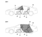
- FIG. 2 is a diagram showing an installation example of the camera 1A and the radar 2A in the vehicle 30.
- FIG. 2A is a diagram showing an installation example of the camera 1A
- FIG. 2B is a diagram showing an installation example of the radar 2A.
- FIG. 3 shows an example of an image of a range 1a that can be imaged by the camera 1A (hereinafter referred to as “capable range”) and a range 2a in which the radar 2A can detect an object in the vehicle interior (hereinafter referred to as “detectable range”) 2a. It is a figure which shows an example of the image of.
- FIG. 3A is a diagram showing an example of an image of the imageable range 1a of the camera 1A
- FIG. 3B is a diagram showing an example of an image of the detectable range 2a of the radar 2A.
- the front seat occupant 33 and the rear seat occupant 34 are seated in the front seat 31 and the rear seat 32, respectively.
- the front seat occupant 33 is the driver and the passenger seat occupant
- the rear seat occupant 34 is the occupant seated behind the passenger seat.
- the front seat occupant 33 and the rear seat occupant 34 are both adults.
- the camera 1A is installed on the instrument panel or dashboard in front of the vehicle interior and captures at least the front seat 31.
- the camera 1A may be shared with, for example, a camera included in a so-called “driver monitoring system (DMS)" mounted on the vehicle 30 for monitoring the state of the driver in the vehicle interior. ..
- DMS driver monitoring system
- the radar 2A is installed above the rear seat 32.
- the upper part of the rear seat 32 is the upper part of the rear seat 32.
- the seat above the seat installed in the passenger compartment, such as the front seat 31 or the rear seat 32 is a state in which the headrest of the seat is at the highest position. It means above the headrest of the seat.
- the radar 2A transmits millimeter waves to the rear seat 32, and receives the reflected waves reflected by the moving object.
- the radar 2A measures the distance from the installation position of the radar 2A to a moving object to which the millimeter wave is reflected by using the transmission / reception result of the millimeter wave.
- the vehicle interior detection device 10 can detect the occupant from the movement of the chest due to breathing, the heartbeat, or the like.
- a blind spot such as a hidden portion in the front seat 31 in the imageable range 1a of the camera 1A
- vehicle interior image There is a blind spot such as a hidden portion in the front seat 31 in the imageable range 1a of the camera 1A
- vehicle interior image There is a blind spot such as a hidden portion in the front seat 31 in the imageable range 1a of the camera 1A
- vehicle interior image There is a blind spot such as a hidden portion in the front seat 31 in the imageable range 1a of the camera 1A
- vehicle interior image the vehicle interior detection device 10 cannot only be seen from the image captured by the camera 1A (hereinafter referred to as “vehicle interior image”).
- vehicle interior image Even if the number of cameras 1A installed is increased to eliminate blind spots that do not appear in the vehicle interior image, the vehicle interior detection device 10 cannot detect an occupant whose entire body is covered with a blanket or the like, for example.
- a method of detecting the occupant by a sensor (membrane switch) installed under the seat is also considered. Be done.
- a sensor membrane switch
- leaving pets or infants in the vehicle interior has become a social problem, and occupant detection in consideration of physical disparity is desired.
- a radio wave sensor that can accurately detect occupants of various physiques, occupants in various postures, or infants on child seats is installed in the vehicle interior, and occupant detection is performed by the radio waves transmitted by the radio wave sensors. Is under consideration.
- the radio waves transmitted by the radio wave sensor can react to the occupants who do not transfer to the image inside the vehicle.
- since radio waves pass through resin, blankets, and the like, occupants whose entire body is covered with blankets and the like can also be detected. In occupant detection using a radio wave sensor, it is also possible to determine the difference in body size of the detected occupant.
- the vehicle interior detection device 10 detects the rear seat occupant 34, which is particularly difficult to detect, by using a radio wave sensor, specifically, a radar 2A.
- the vehicle interior detection device 10 combines the camera 1A and the radar 2A to improve the accuracy of occupant detection. Further, the vehicle interior detection device 10 performs occupant detection in consideration of the physical disparity of the occupants by the millimeter wave transmitted by the radar 2A. The occupant detection in consideration of the occupant's body size difference by the millimeter wave transmitted by the radar 2A will be described later with a specific example.
- the vehicle interior detection device 10 includes an image acquisition unit 11A, a distance acquisition unit 12A, a seat information acquisition unit 13, an occupant detection unit 14, a detection range determination unit 15, and a sensor control unit 16.
- the occupant detection unit 14 includes a front seat occupant detection unit 141 and a rear seat occupant detection unit 142.
- the front seat occupant detection unit 141 includes a front seat occupant position estimation unit 1411.
- the image acquisition unit 11A acquires image data obtained by the camera 1A in the vehicle interior from the camera 1A.
- the image acquisition unit 11A outputs the image data acquired from the camera 1A to the front seat occupant detection unit 141 of the occupant detection unit 14.
- the distance acquisition unit 12A acquires the distance data obtained by measuring the distance to each object in the vehicle interior from the radar 2A.
- the distance acquisition unit 12A outputs the distance data acquired from the radar 2A to the rear seat occupant detection unit 142 of the occupant detection unit 14.
- the seat information acquisition unit 13 acquires seat information.
- the seat information acquisition unit 13 outputs the acquired seat information to the front seat occupant detection unit 141 of the occupant detection unit 14.
- the occupant detection unit 14 detects an occupant existing in the vehicle 30 based on the image data acquired by the image acquisition unit 11A or the distance data acquired by the distance acquisition unit 12A.
- the front seat occupant detection unit 141 of the occupant detection unit 14 detects the front seat occupant 33 based on the image data acquired by the image acquisition unit 11A.
- the front seat occupant detection unit 141 may analyze the vehicle interior image based on the image data using a known image recognition technique and detect the front seat occupant 33.
- the front seat occupant detection unit 141 determines, for example, whether the front seat occupant 33 is dozing, the front seat occupant 33 is drowsy, or the front seat occupant 33 is inattentive, based on the degree of opening of the eyes or the face orientation of the front seat occupant 33. It can also be determined. For example, when the front seat occupant 33 is a passenger in the passenger seat, the front seat occupant detection unit 141 controls a playback control device (not shown) or air conditioning that reproduces music in the vehicle interior based on the determination result of drowsiness or drowsiness. The feedback may be provided to a control device that controls to keep the environment in the vehicle interior comfortable, such as an air conditioning control device (not shown).
- the front seat occupant position estimation unit 1411 uses the image data acquired by the image acquisition unit 11A and the seat information acquired by the seat information acquisition unit 13 to obtain the front seat.
- the position of the occupant 33 is estimated.
- the position of the front seat occupant 33 is the head position of the front seat occupant 33.
- the front seat occupant position estimation unit 1411 sets the center of the face of the front seat occupant 33 on the vehicle interior image based on the image data as the head position of the front seat occupant 33, for example.
- the front seat occupant position estimation unit 1411 first detects the face of the front seat occupant 33 by using a known image recognition technique based on the image data. Then, the front seat occupant position estimation unit 1411 determines the size of the face of the detected front seat occupant 33. The front seat occupant position estimation unit 1411 may determine the size of the face of the front seat occupant 33 based on where the face is on the coordinates of the vehicle interior image based on the image data. The front seat occupant position estimation unit 1411 determines the distance between the camera 1A and the center of the face of the front seat occupant 33 from the determined face size of the front seat occupant 33.
- the standard position of the front seat 31 is that an adult with a standard face size sits in a seat that has a standard slide position, a standard seat height, and a standard backrest tilt. This is the seating position when the seat is closed.
- the front seat occupant position estimation unit 1411 determines the distance between the camera 1A and the center of the face of the front seat occupant 33 by comparing the reference face size with the determined face size of the front seat occupant 33. good. For example, when the size of the face of the front seat occupant 33 is larger than the standard face size, the center of the face of the front seat occupant 33 is closer to the camera 1A by that amount. In other words, the distance between the camera 1A and the center of the face of the front seat occupant 33 is shorter than the distance between the camera 1A and the center of the face of the front seat occupant 33.
- the front seat occupant position estimation unit 1411 determines the current slide position of the front seat 31, the height of the seat surface, and the seat surface height based on the seat information. , Determine the distance between the camera 1A and the face of the front occupant 33, taking into account the standard seat position, seat height, and how much the seat tilt deviates from the seat tilt, respectively. do.
- the front seat occupant position estimation unit 1411 determines the distance between the camera 1A and the center of the face of the front seat occupant 33 only from the vehicle interior image, the camera assumes that the front seat occupant 33 is sitting in a standard position. The distance between 1A and the center of the face of the front seat occupant 33 is determined.
- the front seat occupant position estimation unit 1411 considers the seat information when estimating the position of the front seat occupant 33. By considering the seat information, the front seat occupant position estimation unit 1411 can know that the front seat occupant 33 is sitting in a position in front of the standard position. Then, the front seat occupant position estimation unit 1411 can more accurately determine the distance between the camera 1A and the center of the face of the front seat occupant 33.
- the front seat occupant position estimation unit 1411 can estimate the distance between the camera 1A and the center of the face of the front seat occupant 33, if the distance between the camera 1A and the center of the face of the front seat occupant 33 can be estimated.
- the center position of the face in other words, the position of the front seat occupant 33, can be estimated.
- the front seat occupant position estimation unit 1411 outputs the estimated information regarding the position of the front seat occupant 33 to the detection range determination unit 15.
- the front seat occupant detection unit 141 If the front seat occupant detection unit 141 does not detect the front seat occupant 33, the front seat occupant detection unit 141 outputs information to the effect that the front seat occupant 33 has not been detected to the detection range determination unit 15.
- the rear seat occupant detection unit 142 of the occupant detection unit 14 determines the rear seat occupant 34 of the vehicle 30 based on the distance data acquired by the distance acquisition unit 12A and the detection range of the radar 2A determined by the detection range determination unit 15. Detect. Specifically, for example, the rear seat occupant detection unit 142 detects whether or not the rear seat occupant 34 of the vehicle 30 exists based on the distance data acquired in the detection range of the radar 2A. The rear seat occupant detection unit 142 does not detect the rear seat occupant 34 when the detection range determination unit 15 determines that the radar 2A does not have a detection range.
- the detection range determination unit 15 determines the detection range of the radar 2A based on the position of the front seat occupant 33 estimated by the front seat occupant position estimation unit 1411.
- the detection range determination unit 15 divides the detectable range 2a of the radar 2A into a plurality of areas (hereinafter referred to as “divided areas”), and detects the rear seat occupant 34 in the detectable range 2a of the radar 2A.
- the divided area to be used as the area is determined as the detection range of the radar 2A.
- the detectable range 2a of the radar 2A is a range in which the radar 2A can measure distance data in the vehicle interior, that is, a reflected wave reflected by an object in which the radar 2A transmits a millimeter wave and the millimeter wave moves. Is within the range in which it is possible to receive.
- FIG. 4A shows the state of the passenger compartment in which the front seat occupant 33 and the rear seat occupant 34 are seated in the front seat 31 in the standard position and the rear seat 32 in the standard position, respectively. Both the front seat occupant 33 and the rear seat occupant 34 are adults.
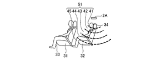
- the detection range determination unit 15 sets the detectable range 2a of the radar 2A to, for example, the first area 41 closer to the installation position of the radar 2A, the second area 42 farther from the installation position than the first area 41, and the second area 42.
- the first area 41, the second area 42, the third area 43, the fourth area 44, the fifth area 45, and the sixth area 46 are divided areas, respectively.
- the first area 41 is an area including the headrest of the rear seat 32.
- the second area 42 and the third area 43 are areas including the backrest of the rear seat 32, and the area including the backrest is divided into an area on the headrest side and an area on the seat surface side of the rear seat 32, and the second area 42. Is the area on the headrest side, and the third area 43 is the area on the seat surface side.
- the fourth area 44 is an area including the seating surface of the rear seat 32.
- the fifth area 45 and the sixth area 46 are areas including the feet of the rear seats 32.
- the radar 2A detects the widest possible range. It is desirable to set it to the range.
- the detection range of the radar 2A needs to be a range in which the front seat occupant 33 does not enter so that the front seat occupant 33 is not erroneously detected as the rear seat occupant 34.
- the rear seat occupant detection unit 142 will erroneously detect the front seat occupant 33 as the rear seat occupant 34 based on the distance data classified into the fourth area 44, the fifth area 45, and the sixth area 46.
- the state of the passenger compartment is such that the front seat occupant 33 is seated with the slide position of the front seat 31 largely shifted to the rear seat 32 side.
- a rear seat occupant 34 is seated in the rear seat 32. Both the front seat occupant 33 and the rear seat occupant 34 are adults.
- the vehicle interior is as shown in FIG. 4B, not only the fourth area 44, the fifth area 45, and the sixth area 46 but also the third area 43 is included in the detection range of the radar 2A.
- the rear seat occupant detection unit 142 sets the front occupant 33 as the rear occupant 34 based on the distance data classified into the third area 43, the fourth area 44, the fifth area 45, or the sixth area 46. It will be falsely detected.
- FIG. 4B it is assumed that the rear seat occupant 34 is present in the rear seat 32, but even if the rear seat occupant 34 is not present in the rear seat 32, the rear seat occupant detection unit 142 is in the third area. Based on the distance data classified into 43, the 4th area 44, the 5th area 45, and the 6th area 46, the front seat occupant 33 is erroneously detected as the rear seat occupant 34.
- the detection range of the radar 2A is fixedly determined so that the third area 43 to the sixth area 46 are not included in the detection range, assuming that the vehicle interior state as shown in FIG. 4B can be obtained. .. Then, there is a possibility that the rear seat occupant detection unit 142 may erroneously detect the rear seat occupant 34.
- the state of the vehicle interior is such that an infant 35 placed on a child seat exists as a rear seat occupant 34 in the rear seat 32. There are no occupants other than infant 35.
- the rear seat occupant detection unit 142 must be included in the detection range of the radar 2A unless the third area 43 or the fourth area 44 is included in the detection range of the radar 2A. If the occupant 34 does not exist, it will be erroneously detected.
- the detection range of the radar 2A is set so as to include an area within the detectable range 2a (1st area 41 to 6th area 46) as wide as possible and the rear seat occupant 34 is not erroneously detected. Need to be. Therefore, the detection range determination unit 15 dynamically determines the detection range of the radar 2A based on the position of the front seat occupant 33.
- FIG. 5 is a diagram for explaining an example of the detection range of the radar 2A determined by the detection range determination unit 15.
- the detection range of the radar 2A determined by the detection range determination unit 15 is shown as the detection range 51.
- the detection range determination unit 15 prevents the front seat occupant 33 from being erroneously detected as the rear seat occupant 34 in the first area 41 and the second area. 42 and the third area 43 are determined to be the detection range 51 of the radar 2A (see FIG. 5A).
- the rear seat occupant detection unit 142 when the distance data is classified into the first area 41, the second area 42, or the third area 43, that is, the millimeter wave transmitted by the radar 2A is the first area 41, the first area 41. It is assumed that the rear seat occupant 34 can detect the reflection in the second area 42 or the third area 43.
- the rear seat occupant detection unit 142 determines the physique of the detected rear seat occupant 34 according to which area the distance data is classified into, and based on the determination result, whether the rear seat occupant 34 is an adult, an infant 35, or a pet. , Can also be determined. Specifically, for example, when the distance data is classified into the first area 41, the rear seat occupant detection unit 142 determines that the detected rear seat occupant 34 is an adult. Further, for example, when the distance data is classified into the third area 43, the rear seat occupant detection unit 142 determines that the detected rear seat occupant 34 is an infant 35.
- the adult is a occupant having a physique that can go out of the vehicle by himself / herself even if left behind in the vehicle 30, and the infant 35 is outside the vehicle by himself / herself when left in the vehicle 30. It is a occupant with a physique that is difficult to get out of.
- the detection range determination unit 15 does not erroneously detect the front seat occupant 33 as the rear seat occupant 34, and the first area 41 and the second area 42 is determined to be the detection range 51 of the radar 2A (see FIG. 5B).
- the distance data is classified into the first area 41 and the second area 42, that is, the millimeter wave transmitted by the radar 2A is reflected by the rear seat occupant detection unit 142 in the first area 41 or the second area 42. In this case, it is assumed that the rear seat occupant 34 can detect it.
- the detection range determination unit 15 does not erroneously detect that the rear seat occupant 34 does not exist even though the rear seat occupant 34 exists.
- the first area 41, the second area 42, the third area 43, the fourth area 44, the fifth area 45, and the sixth area 46 are determined as the detection range 51 of the radar 2A (see FIG. 5C).
- the first area 41, the second area 42, the third area 43, and the fourth area 44 can be set as the detection range 51 of the radar 2A.
- the rear seat occupant detection unit 142 can detect the infant 35.
- the detection range determination unit 15 sets the detection range 51 of the radar 2A as wide as possible. That is, the detection range determination unit 15 includes the fifth area 45 and the sixth area 46 in the detection range 51 of the radar 2A.
- the rear seat occupant detection unit 142 detects the rear seat occupant 34 more reliably than in the case where the detection range 51 of the radar 2A does not include the fifth area 45 and the sixth area 46. Will be able to. Specifically, for example, even if there is an infant 35 playing at the feet, or even if a pet (not shown) is present at the feet, the rear seat occupant detection unit 142 may use the infant 35 or the pet. Can be detected (see FIG. 5D).
- the detection range determination unit 15 does not erroneously detect the front seat occupant 33 as the rear seat occupant 34, so that the detection range of the radar 2A should be as wide as possible.
- the detectable range 2a of the radar 2A is defined as the detection range of the radar 2A.
- the detection range determination unit 15 acquires information from the front seat occupant detection unit 141 that the front seat occupant 33 is not detected.
- the detection range determination unit 15 can also determine that there is no detection range of the radar 2A.
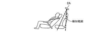
- FIG. 6 is a diagram showing an example of a state in the vehicle interior when the detection range determination unit 15 determines that the radar 2A has no detection range in the first embodiment.
- the state of the passenger compartment is such that the front seat occupant 33 greatly tilts the backrest of the front seat 31 toward the rear seat 32.
- the front seat occupant 33 is an adult.
- the position of the front seat occupant 33 greatly invades the detectable range 2a (first area 41 to sixth area 46) of the radar 2A.
- the rear seat occupant detection unit 142 erroneously detects the front seat occupant 33 as the rear seat occupant 34.
- the detection range determination unit 15 determines that the detection of the rear seat occupant 34 based on the distance data is impossible, and the radar It is determined that there is no detection range of 2A.
- the detection range determination unit 15 determines whether or not the position of the front seat occupant 33 has largely invaded the detectable range 2a of the radar 2A, and the position of the front seat occupant 33 is the area where the rear seat occupant cannot be detected in the vehicle interior. Judgment is made based on whether or not it is inside.
- the area where the rear seat occupants cannot be detected can be set as appropriate.
- the rear seat occupant undetectable region may be, for example, the region of the second area 42 in the detectable range 2a of the radar 2A, or may be a predetermined region in the vehicle interior.
- the detection range determination unit 15 dynamically determines the detection range of the radar 2A based on the position of the front seat occupant 33 estimated by the front seat occupant position estimation unit 1411.
- the detection range determination unit 15 outputs the determined information regarding the detection range of the radar 2A to the rear seat occupant detection unit 142.
- the detection range determination unit 15 determines that there is no detection range of the radar 2A, the detection range determination unit 15 outputs information to the effect that the detection range of the radar 2A is not present to the rear seat occupant detection unit 142 and the sensor control unit 16.
- the sensor control unit 16 turns off the power of the radar 2A. Specifically, the sensor control unit 16 transmits, for example, a control signal for turning off the power of the radar 2A to the radar 2A.
- FIG. 7 is a flowchart for explaining the operation of the vehicle interior detection device 10 according to the first embodiment.
- the image acquisition unit 11A acquires the image data obtained by the camera 1A in the vehicle interior from the camera 1A (step ST701).
- the image acquisition unit 11A outputs the image data acquired from the camera 1A to the front seat occupant detection unit 141 of the occupant detection unit 14.
- the seat information acquisition unit 13 acquires seat information (step ST702).
- the seat information acquisition unit 13 outputs the acquired seat information to the front seat occupant detection unit 141.
- the front seat occupant detection unit 141 detects the front seat occupant 33 of the vehicle 30 based on the image data acquired by the image acquisition unit 11A in step ST701 (step ST703).
- the front seat occupant detection unit 141 outputs information to the effect that the front seat occupant 33 has not been detected to the detection range determination unit 15. Then, the operation of the vehicle interior detection device 10 skips step ST704 and proceeds to step ST705.
- the front seat occupant position estimation unit 1411 acquires the image data acquired by the image acquisition unit 11A in step ST701 and the seat information in step ST702. Based on the seat information acquired by the unit 13, the position of the front seat occupant 33 is estimated (step ST704).
- the front seat occupant position estimation unit 1411 outputs the estimated information regarding the position of the front seat occupant 33 to the detection range determination unit 15.
- the detection range determination unit 15 determines the detection range of the radar 2A based on the position of the front seat occupant 33 estimated by the front seat occupant position estimation unit 1411 in step ST704 (step ST705).
- the detection range determination unit 15 outputs the determined information regarding the detection range of the radar 2A to the rear seat occupant detection unit 142. When the detection range determination unit 15 determines that there is no detection range of the radar 2A, the detection range determination unit 15 outputs information to the effect that the detection range of the radar 2A is not present to the rear seat occupant detection unit 142 and the sensor control unit 16.
- the distance acquisition unit 12A acquires distance data from the radar 2A obtained by measuring the distance to each object in the vehicle interior by the radar 2A (step ST706).
- the distance acquisition unit 12A outputs the distance data acquired from the radar 2A to the rear seat occupant detection unit 142.
- the rear seat occupant detection unit 142 is the rear seat of the vehicle 30 based on the distance data acquired by the distance acquisition unit 12A in step ST706 and the detection range of the radar 2A determined by the detection range determination unit 15 in step ST705. Detects the occupant 34 (step ST707).
- the rear seat occupant detection unit 142 does not detect the rear seat occupant 34 when the detection range determination unit 15 determines that the radar 2A does not have a detection range. In this case, the sensor control unit 16 turns off the power of the radar 2A.
- the operations of steps ST701 to ST705 and the operations of step ST706 are performed in parallel. Further, in the flowchart of FIG. 7, the vehicle interior detection device 10 operates in the order of step ST701 and step ST702, but the vehicle interior detection device 10 operates in the order of step ST702 and step ST701. May be good.
- the vehicle interior detection device 10 determines the detection range of the radar 2A based on the position of the front seat occupant 33 estimated from the image data. Then, the vehicle interior detection device 10 detects the rear seat occupant 34 based on the distance data acquired from the radar 2A and the determined detection range of the radar 2A. Since the vehicle interior detection device 10 dynamically determines the detection range of the radar 2A according to the position of the front seat occupant 33, the rear seat occupant 34 is detected in consideration of the seated state of the front seat occupant 33. be able to.
- the detected occupant information includes information on whether or not an occupant has been detected, information on whether the detected occupant is a front seat occupant 33 or a rear seat occupant 34, or the detected occupant is an adult or an adult. Information such as whether it is not (infant 35 or pet) is included.
- the vehicle interior detection device 10 can perform occupant detection in consideration of the physical disparity depending on which division area the distance data is classified in the detection range of the radar 2A.
- the output unit of the vehicle interior detection device 10 outputs the detection occupant information to an external device (not shown).
- the external device may be, for example, at least one of a speaker or a display mounted on the vehicle 30, a occupant in the vehicle 30, a mobile terminal owned by the owner of the vehicle 30, and the like. It may be a hazard lamp or a horn (horn) mounted on the vehicle 30.
- the detected occupant information is used in the vehicle theft prevention function.
- the control unit (not shown) of the vehicle 30 detects the application of a large impact to the vehicle 30 or the opening / closing of the door in a locked state while the vehicle 30 is parked.
- the vehicle interior detection device 10 activates the camera 1A and the radar 2A, acquires image data and distance data from the camera 1A and the radar 2A, respectively, and detects a person existing in the vehicle interior.
- the vehicle interior detection device 10 outputs the detected occupant information to the mobile terminal owned by the owner of the vehicle 30.
- the owner of the vehicle 30 can detect, for example, the intrusion of someone into the vehicle 30.
- the vehicle interior detection device 10 outputs the image data acquired from the camera 1A together with the detection occupant information to the security system.
- the vehicle interior detection device 10 and the security system are connected via a network.
- the control of the vehicle 30 remotely performed by the security system is, for example, a control that does not turn on the engine.
- the vehicle interior detection device 10 detects an occupant while the vehicle 30 is stopped, the detected occupant information is used in the infant leaving detection function.
- the vehicle interior detection device 10 outputs the detection occupant information to the infant leaving detection device (not shown).
- the vehicle interior detection device 10 and the infant abandonment detection device are connected via a network.
- the infant abandonment detection device determines that the infant abandonment may have occurred when, for example, the detection occupant information indicating that the infant 35 has been detected is output from the vehicle interior detection device 10. At this time, if it can be determined from the detected occupant information that an adult is also detected in addition to the infant 35, the infant abandonment detection device is not an infant abandonment, for example, the vehicle owner (adult) intentionally takes a break or takes a break in the vehicle interior.
- the vehicle interior detection device 10 outputs the image data acquired from the camera 1A together with the detection occupant information to the infant abandonment detection device, and the infant abandonment detection device includes an adult in addition to the infant 35 from the image data. It may be determined whether or not.
- the vehicle interior detection device 10 detects an occupant while the vehicle 30 is traveling, the detected occupant information is used in the seatbelt reminder.
- the vehicle interior detection device 10 includes a processing circuit 801 for controlling to detect an occupant in the vehicle interior of the vehicle 30.
- the processing circuit 801 may be dedicated hardware as shown in FIG. 8A, or may be a CPU (Central Processing Unit) 805 that executes a program stored in the memory 806 as shown in FIG. 8B.
- CPU Central Processing Unit
- the processing circuit 801 may be, for example, a single circuit, a composite circuit, a programmed processor, a parallel programmed processor, an ASIC (Application Specific Integrated Circuit), or an FPGA (Field-Programmable). Gate Array) or a combination of these is applicable.
- the processing circuit 801 is the CPU 805, the functions of the image acquisition unit 11A, the distance acquisition unit 12A, the seat information acquisition unit 13, the occupant detection unit 14, the detection range determination unit 15, and the sensor control unit 16 are software. It is realized by firmware or a combination of software and firmware. That is, the image acquisition unit 11A, the distance acquisition unit 12A, the seat information acquisition unit 13, the occupant detection unit 14, the detection range determination unit 15, and the sensor control unit 16 are HDD (Hard Disk Drive) 802 and memory 806. It is realized by a processing circuit such as a CPU 805 that executes a program stored in the above and a system LSI (Large-Scale Integration). The programs stored in the HDD 802, the memory 806, etc.
- HDD Hard Disk Drive
- the memory 806 is, for example, a RAM (Random Access Memory), a ROM (Read Only Memory), a flash memory, an EPROM (Erasable Programmable Read Only Memory), an EEPROM (Electrically), etc.
- a sexual or volatile semiconductor memory, a magnetic disk, a flexible disk, an optical disk, a compact disk, a mini disk, a DVD (Digital Versaille Disc), or the like is applicable.
- the functions of the image acquisition unit 11A, the distance acquisition unit 12A, the seat information acquisition unit 13, the occupant detection unit 14, the detection range determination unit 15, and the sensor control unit 16 are partially provided with dedicated hardware. It may be realized and partly realized by software or firmware.
- the image acquisition unit 11A, the distance acquisition unit 12A, and the seat information acquisition unit 13 are realized by the processing circuit 801 as dedicated hardware, and the occupant detection unit 14, the detection range determination unit 15, and the sensor control are realized.
- the function of the unit 16 can be realized by the processing circuit 801 reading and executing the program stored in the memory 806.
- the vehicle interior detection device 10 includes a device such as a camera 1A, a radar 2A, or an external device, and an input interface device 803 and an output interface device 804 for performing wired communication or wireless communication.
- the detection range determination unit 15 determines whether or not the detectable range 2a in which the radar 2A can measure the distance data can be used for detecting the rear seat occupant 34. Dividing into a plurality of divided areas (1st area 41, 2nd area 42, 3rd area 43, 4th area 44, 5th area 45, and 6th area 46), and changing the divided area. So, the detection range of the radar 2A was dynamically determined. However, this is just one example. The detection range determination unit 15 may dynamically determine the detection range of the radar 2A by changing the direction in which the radar 2A transmits millimeter waves. Further, the detection range determination unit 15 may determine the detection range of the radar 2A by the combination of the divided area and the direction in which the radar 2A transmits millimeter waves.
- the detection range determination unit 15 has the detectable range 2a of the radar 2A (first area 41 to sixth area). Of 46), an example in which the first area 41 and the second area 42 are set as the detection range of the radar 2A has been described (see FIG. 5B).
- the detection range determining unit 15 directs the radar 2A to transmit millimeter waves toward the rear seat 32 and then the front seat. A divided area that does not include the position of the occupant 33 may be determined as the detection range of the radar 2A.
- FIG. 9 when the state of the vehicle interior is as shown in FIG.
- the detection range determining unit 15 directs the radar 2A to transmit the millimeter wave toward the rear seat 32 side. It is a figure for demonstrating an example of the image of the detection range when the division area which does not include the position of the front seat occupant 33 is determined to be the detection range of the radar 2A.
- the detection range determining unit 15 makes the millimeter wave transmitted from the radar 2A toward the substantially center of the detectable range 2a transmitted toward the headrest of the rear seat 32, and then first. Area 41, the second area 42, the third area 43, the fourth area 44, and the fifth area 45 are set as the detection range of the radar 2A.
- the detection range determination unit 15 may change the direction in which the radar 2A transmits millimeter waves via the sensor control unit 16.
- the radar 2A is installed above the rear seat 32 (see FIGS. 2, 4 to 6), but this is only an example.
- the radar 2A may be installed in the vehicle interior above the seats installed in the vehicle interior.
- the radar 2A may be installed in a pillar, for example, as long as it is installed above the seat installed in the vehicle interior. It is desirable that the radar 2A is installed above the seats installed in the vehicle interior and further above the rear seats 32 on the front seats 31 side. This is because, for example, when an iron plate is embedded in the backrest portion of the rear seat 32, the millimeter wave transmitted by the radar 2A may not pass through the rear seat 32 due to the iron plate. If the millimeter wave is not transmitted, the vehicle interior detection device 10 cannot detect the rear seat occupant 34 of the rear seat 32.
- FIG. 10 shows an example of the installation position of the radar 2A when the radar 2A is installed at a place other than above the rear seat 32, and the detection range 1001 of the radar 2A determined by the detection range determination unit 15. It is a figure for demonstrating an example.
- FIG. 10 it is assumed that the radar 2A is installed above the front seat 31.
- the radar 2A is installed above the front seat 31 when the front seat 31 is in a standard position.
- FIG. 10A shows the state of the passenger compartment in which the front seat occupant 33 and the rear seat occupant 34 are seated in the front seat 31 in the standard position and the rear seat 32 in the standard position, respectively, as in FIG. 4A.
- FIG. 10B shows the front seat occupant 33 is seated with the slide position of the front seat 31 largely shifted to the rear seat 32 side, and the rear seat occupant 34 is seated in the rear seat 32. It shows the state of the room.
- the detection range determination unit 15 divides the detectable range 2a of the radar 2A into a plurality of division areas.
- the detection range determination unit 15 transmits the detectable range 2a, for example, the millimeter wave from the radar 2A toward the rearmost side in the traveling direction of the vehicle 30, the first area 101, the first.
- the second area 102 on the front side of the vehicle 30 with respect to the traveling direction of the vehicle 30 (hereinafter, simply referred to as "the front side of the vehicle 30"), and the third area 103 on the front side of the vehicle 30 with respect to the second area 102.
- the first area 101 to the eighth area 108 are divided areas, respectively.
- the first area 101 is an area including the headrest of the rear seat 32.
- the second area 102 and the third area 103 are areas including the backrest of the rear seat 32, and the area including the backrest is divided into an area on the headrest side and an area on the seat surface side of the rear seat 32, and the second area 102. Is the area on the headrest side, and the third area 103 is the area on the seat surface side.
- the fourth area 104 is an area including the seating surface of the rear seat 32.
- the fifth area 105 is an area including the feet of the rear seats 32.
- the sixth area 106 and the seventh area 107 are areas including the front seats 31, and the eighth area 108 is an area including the feet of the front seats 31.
- the detection range determination unit 15 can also divide the detectable range 2a along the direction in which the millimeter wave from the radar 2A is transmitted.
- the detection range determination unit 15 is divided according to the distance from the installation position of the radar 2A (see, for example, the first area 41 to the sixth area 46 in FIG. 4) and the division as shown in FIG. 10A.
- the detectable range 2a may be divided into division areas in combination with the above-mentioned method.
- the rear seat occupant detection unit 142 may use the fourth area 104. Based on the distance data classified into the eighth area 108, the front seat occupant 33 is erroneously detected as the rear seat occupant 34. Therefore, the detection range determination unit 15 radars the first area 101, the second area 102, and the third area 103 so that the rear seat occupant detection unit 142 does not erroneously detect the front seat occupant 33 as the rear seat occupant 34.
- the detection range of 2A is determined to be 1001.
- the rear seat occupant detection unit 142 erroneously detects the front seat occupant 33 as the rear seat occupant 34 based on the distance data classified into the third area 103 to the eighth area 108.
- FIG. 10B it is assumed that the rear seat occupant 34 exists in the rear seat 32, but even if the rear seat occupant 34 does not exist in the rear seat 32, the rear seat occupant detection unit 142 still has the front seat occupant. 33 is detected as the rear seat occupant 34. Therefore, the detection range determination unit 15 determines the first area 101 and the second area 102 as the detection range 1001 of the radar 2A so that the front seat occupant 33 is not erroneously detected as the rear seat occupant 34.
- the detection range determination unit 15 can divide the detectable range 2a according to the width of the range in which millimeter waves are transmitted from the radar 2A. Therefore, for example, as shown in FIG. 6, when the front seat occupant 33 is in a state where the backrest of the front seat 31 is greatly tilted toward the rear seat 32, the detection range determination unit 15 determines the state.
- the detectable range 2a can be divided according to the width of the range in which the millimeter wave is transmitted, and the divided area along the backrest of the rear seat 32 can be set as the detection range (see FIG. 11).
- the rear seat occupant detection unit 142 can detect the rear seat occupant 34 without erroneously detecting the front seat occupant 33 as the rear seat occupant 34.
- the rear seat occupant detection unit 142 cannot detect the occupant who has determined the physical disparity. Specifically, when the rear seat occupant 34 is present, the rear seat occupant detection unit 142 cannot determine whether the rear seat occupant 34 is an adult, a child, or an infant.
- the front seat occupant position estimation unit 1411 determines the position of the front seat occupant 33 based on the image data acquired by the image acquisition unit 11A and the seat information acquired by the seat information acquisition unit 13. Is estimated, but this is just an example.
- the front seat occupant position estimation unit 1411 may estimate the position of the front seat occupant 33 only from the image data without using the seat information.
- the vehicle interior detection device 10 may be configured not to include the seat information acquisition unit 13.
- the vehicle interior detection device 10 is provided with the sensor control unit 16, but the vehicle interior detection device 10 is not essential to include the sensor control unit 16. However, the vehicle interior detection device 10 can prevent unnecessary operation of the radar 2A by including the sensor control unit 16.
- the position of the front seat occupant 33 is the head position of the front seat occupant 33, but this is only an example.
- the position of the front seat occupant 33 may be, for example, the position of the shoulder of the front seat occupant 33 or the position of the arm of the front seat occupant 33.
- the front seat occupant detection unit 141 detects the front seat occupant 33 based on the image data acquired by the image acquisition unit 11A, but this is only an example.
- the rear seat occupant detection unit 142 may detect the rear seat occupant 34 and the front seat occupant 33 based on the distance data acquired by the distance acquisition unit 12A.
- the radar 2A is installed at the position shown in FIG. 10
- the rear seat occupant detection unit 142 can detect the front seat occupant 33 based on the distance data.
- the first sensor 1 is the camera 1A, but the first sensor 1 may be the radar.
- the vehicle interior detection device 10 is an in-vehicle device mounted on the vehicle 30, and has an image acquisition unit 11A, a distance acquisition unit 12A, a seat information acquisition unit 13, a occupant detection unit 14, and a detection range. It is assumed that the determination unit 15 and the sensor control unit 16 are provided in the vehicle interior detection device 10. Not limited to this, a part of the image acquisition unit 11A, the distance acquisition unit 12A, the seat information acquisition unit 13, the occupant detection unit 14, the detection range determination unit 15, and the sensor control unit 16 is mounted on the vehicle-mounted device of the vehicle.
- the vehicle interior detection system may be configured by the vehicle-mounted device and the server, assuming that the other is provided in the server connected to the vehicle-mounted device via the network.
- the vehicle interior detection device 10 is installed above the seat in the vehicle interior and the first data acquisition unit 11 that acquires the first data acquired by the first sensor 1.
- the front seat that estimates the position of the front seat occupant 33 based on the second data acquisition unit 12 that acquires the second data acquired by the second sensor 2 and the first data acquired by the first data acquisition unit 11.
- the detection range determination unit 15 for determining the detection range of the second sensor 2 and the second data acquisition unit 12 based on the positions of the front seat occupant 33 estimated by the occupant position estimation unit 1411 and the front seat occupant position estimation unit 1411.
- the rear seat occupant detection unit 142 that detects the rear seat occupant 34 based on the second data acquired by the user and the detection range of the second sensor 2 determined by the detection range determination unit 15 is provided. Therefore, the vehicle interior detection device 10 can detect the rear seat occupant 34 in consideration of the seated state of the front seat occupant 33.
- the position of the front seat occupant 33 estimated by the front seat occupant position estimation unit 1411 is the area where the rear seat occupant cannot be detected in the vehicle interior. If it is inside, it is determined that there is no detection range of the second sensor 2, and if the detection range determination unit 15 determines that there is no detection range of the second sensor 2, the sensor control unit 16 that turns off the power of the second sensor 2. It was configured to be equipped with. Therefore, the vehicle interior detection device 10 can prevent unnecessary operation of the radar 2A.
- the vehicle interior detection device detects the occupants in the rear seats in consideration of the seated state of the occupants in the front seats. Suitable for use in indoor detection devices.
Landscapes
- Engineering & Computer Science (AREA)
- Physics & Mathematics (AREA)
- Mechanical Engineering (AREA)
- General Physics & Mathematics (AREA)
- Mathematical Physics (AREA)
- Transportation (AREA)
- Automation & Control Theory (AREA)
- Multimedia (AREA)
- Theoretical Computer Science (AREA)
- Seats For Vehicles (AREA)
- Air Bags (AREA)
- Automotive Seat Belt Assembly (AREA)
- Geophysics And Detection Of Objects (AREA)
Priority Applications (5)
| Application Number | Priority Date | Filing Date | Title |
|---|---|---|---|
| PCT/JP2020/019884 WO2021234836A1 (ja) | 2020-05-20 | 2020-05-20 | 車室内検知装置、および、車室内検知方法 |
| JP2022523556A JP7109707B2 (ja) | 2020-05-20 | 2020-05-20 | 車室内検知装置、および、車室内検知方法 |
| DE112020006871.4T DE112020006871B4 (de) | 2020-05-20 | 2020-05-20 | Fahrgastzelleinnenraumerkennungsvorrichtung und Fahrgastzelleinnenraumerkennungsverfahren |
| US17/918,281 US12145596B2 (en) | 2020-05-20 | 2020-05-20 | Cabin-inside detection device and cabin-inside detection method |
| CN202080100777.9A CN115551749B (zh) | 2020-05-20 | 2020-05-20 | 车厢内检测装置及车厢内检测方法 |
Applications Claiming Priority (1)
| Application Number | Priority Date | Filing Date | Title |
|---|---|---|---|
| PCT/JP2020/019884 WO2021234836A1 (ja) | 2020-05-20 | 2020-05-20 | 車室内検知装置、および、車室内検知方法 |
Publications (1)
| Publication Number | Publication Date |
|---|---|
| WO2021234836A1 true WO2021234836A1 (ja) | 2021-11-25 |
Family
ID=78708274
Family Applications (1)
| Application Number | Title | Priority Date | Filing Date |
|---|---|---|---|
| PCT/JP2020/019884 Ceased WO2021234836A1 (ja) | 2020-05-20 | 2020-05-20 | 車室内検知装置、および、車室内検知方法 |
Country Status (5)
| Country | Link |
|---|---|
| US (1) | US12145596B2 (https=) |
| JP (1) | JP7109707B2 (https=) |
| CN (1) | CN115551749B (https=) |
| DE (1) | DE112020006871B4 (https=) |
| WO (1) | WO2021234836A1 (https=) |
Cited By (2)
| Publication number | Priority date | Publication date | Assignee | Title |
|---|---|---|---|---|
| WO2023143973A1 (de) * | 2022-01-25 | 2023-08-03 | Brose Fahrzeugteile SE & Co. Kommanditgesellschaft, Coburg | Verfahren zum betrieb eines radarsensorsystems zur innenraumüberwachung eines kraftfahrzeugs |
| JPWO2023195060A1 (https=) * | 2022-04-05 | 2023-10-12 |
Families Citing this family (6)
| Publication number | Priority date | Publication date | Assignee | Title |
|---|---|---|---|---|
| JP7560022B2 (ja) * | 2020-07-27 | 2024-10-02 | 株式会社テクノアクセルネットワークス | 車両用安全支援システム |
| JP7258260B2 (ja) | 2021-01-29 | 2023-04-14 | 三菱電機株式会社 | 乗員判定装置及び乗員判定方法 |
| JPWO2024116256A1 (https=) * | 2022-11-29 | 2024-06-06 | ||
| KR102808292B1 (ko) * | 2022-12-02 | 2025-05-20 | 주식회사 에이치엘클레무브 | 후석 감지 장치 및 후석 감지 방법 |
| DE102024111196A1 (de) * | 2024-04-22 | 2025-10-23 | Bayerische Motoren Werke Aktiengesellschaft | Verfahren und System zur Erkennung und Überwachung eines in einem Innenraum eines Fahrzeugs angeordneten Kindersitzes, sowie Kindersitz |
| CN119840542B (zh) * | 2025-03-24 | 2025-07-18 | 江苏开沃汽车有限公司 | 车辆内遗忘活体及外物入侵监测方法、装置及设备 |
Citations (5)
| Publication number | Priority date | Publication date | Assignee | Title |
|---|---|---|---|---|
| JPH11295440A (ja) * | 1998-04-15 | 1999-10-29 | Denso Corp | 車両用乗員検出装置 |
| JP2005138775A (ja) * | 2003-11-10 | 2005-06-02 | Denso Corp | 車両用温度検出装置および車両用空調装置 |
| JP2006159979A (ja) * | 2004-12-03 | 2006-06-22 | Mazda Motor Corp | 車両用シート装置 |
| JP2010083297A (ja) * | 2008-09-30 | 2010-04-15 | Denso Corp | シート制御システム |
| US20180111575A1 (en) * | 2016-10-26 | 2018-04-26 | Ford Global Technologies, Llc | Gap based airbag deployment |
Family Cites Families (15)
| Publication number | Priority date | Publication date | Assignee | Title |
|---|---|---|---|---|
| US8152198B2 (en) * | 1992-05-05 | 2012-04-10 | Automotive Technologies International, Inc. | Vehicular occupant sensing techniques |
| JP2004020247A (ja) * | 2002-06-13 | 2004-01-22 | Mitsubishi Electric Corp | 乗員検出装置 |
| JP4623501B2 (ja) | 2005-02-18 | 2011-02-02 | タカタ株式会社 | 検知システム、報知装置、駆動装置、車両 |
| JP2008261749A (ja) * | 2007-04-12 | 2008-10-30 | Takata Corp | 乗員検出装置、作動装置制御システム、シートベルトシステム、車両 |
| JP5262181B2 (ja) * | 2008-02-27 | 2013-08-14 | 株式会社ニコン | 車載カメラシステムおよびその電源制御方法。 |
| JP6645416B2 (ja) * | 2016-12-20 | 2020-02-14 | 株式会社デンソー | 乗員検出装置、乗員検出システム、乗員検出方法 |
| JP2018202921A (ja) | 2017-05-31 | 2018-12-27 | パナソニックIpマネジメント株式会社 | 乗員状態検知システム |
| JP2019034693A (ja) * | 2017-08-21 | 2019-03-07 | 株式会社デンソー | 車両用空調装置 |
| JP2019060608A (ja) * | 2017-09-22 | 2019-04-18 | アイシン精機株式会社 | 乗員体格判定装置 |
| KR102506860B1 (ko) * | 2017-11-22 | 2023-03-08 | 현대자동차주식회사 | 차량 내 객체 검출 장치 및 방법 |
| JP2019123354A (ja) * | 2018-01-16 | 2019-07-25 | 株式会社デンソー | 乗員検知装置 |
| JP2019177852A (ja) | 2018-03-30 | 2019-10-17 | 株式会社フジクラ | 乗員検知装置および乗員検知方法 |
| US20220172489A1 (en) * | 2018-05-09 | 2022-06-02 | Motherson Innovations Company Limited | Systems and methods for object detection in the interior of a motor vehicle |
| KR102598956B1 (ko) * | 2018-10-15 | 2023-11-07 | 현대자동차주식회사 | 차량 승객 감지 장치, 그를 포함한 시스템 및 그 방법 |
| US11543511B2 (en) * | 2019-03-11 | 2023-01-03 | Panasonic Intellectual Property Management Co., Ltd. | Radar apparatus and vehicle |
-
2020
- 2020-05-20 US US17/918,281 patent/US12145596B2/en active Active
- 2020-05-20 DE DE112020006871.4T patent/DE112020006871B4/de active Active
- 2020-05-20 CN CN202080100777.9A patent/CN115551749B/zh active Active
- 2020-05-20 JP JP2022523556A patent/JP7109707B2/ja active Active
- 2020-05-20 WO PCT/JP2020/019884 patent/WO2021234836A1/ja not_active Ceased
Patent Citations (5)
| Publication number | Priority date | Publication date | Assignee | Title |
|---|---|---|---|---|
| JPH11295440A (ja) * | 1998-04-15 | 1999-10-29 | Denso Corp | 車両用乗員検出装置 |
| JP2005138775A (ja) * | 2003-11-10 | 2005-06-02 | Denso Corp | 車両用温度検出装置および車両用空調装置 |
| JP2006159979A (ja) * | 2004-12-03 | 2006-06-22 | Mazda Motor Corp | 車両用シート装置 |
| JP2010083297A (ja) * | 2008-09-30 | 2010-04-15 | Denso Corp | シート制御システム |
| US20180111575A1 (en) * | 2016-10-26 | 2018-04-26 | Ford Global Technologies, Llc | Gap based airbag deployment |
Cited By (4)
| Publication number | Priority date | Publication date | Assignee | Title |
|---|---|---|---|---|
| WO2023143973A1 (de) * | 2022-01-25 | 2023-08-03 | Brose Fahrzeugteile SE & Co. Kommanditgesellschaft, Coburg | Verfahren zum betrieb eines radarsensorsystems zur innenraumüberwachung eines kraftfahrzeugs |
| JPWO2023195060A1 (https=) * | 2022-04-05 | 2023-10-12 | ||
| WO2023195060A1 (ja) * | 2022-04-05 | 2023-10-12 | 三菱電機株式会社 | 乗員検知装置および乗員検知方法 |
| JP7499997B2 (ja) | 2022-04-05 | 2024-06-14 | 三菱電機株式会社 | 乗員検知装置および乗員検知方法 |
Also Published As
| Publication number | Publication date |
|---|---|
| CN115551749A (zh) | 2022-12-30 |
| US12145596B2 (en) | 2024-11-19 |
| US20230166737A1 (en) | 2023-06-01 |
| CN115551749B (zh) | 2026-01-02 |
| JP7109707B2 (ja) | 2022-07-29 |
| DE112020006871T5 (de) | 2023-01-12 |
| DE112020006871B4 (de) | 2024-06-13 |
| JPWO2021234836A1 (https=) | 2021-11-25 |
Similar Documents
| Publication | Publication Date | Title |
|---|---|---|
| JP7109707B2 (ja) | 車室内検知装置、および、車室内検知方法 | |
| AU682267B2 (en) | Automotive occupant sensor system and method of operation by sensor fusion | |
| KR102506860B1 (ko) | 차량 내 객체 검출 장치 및 방법 | |
| EP3831647A1 (en) | Vehicle occupant detection device | |
| JP7751403B2 (ja) | 車両の乗員置去判定装置 | |
| US20110246026A1 (en) | Vehicle console control system | |
| US11549303B2 (en) | Vehicle control device, vehicle control method, and recording medium | |
| US11726651B2 (en) | Vehicle occupant detection system | |
| CN107818277A (zh) | 用于监视车辆的车辆内室的方法和设备 | |
| CN110023784B (zh) | 障碍物检测装置 | |
| US10422874B2 (en) | Method and system for spatial modeling of an interior of a vehicle | |
| US11915574B2 (en) | Alert system to output alert about occupant left in vehicle | |
| KR102808292B1 (ko) | 후석 감지 장치 및 후석 감지 방법 | |
| JP2020084573A (ja) | 開閉体制御装置 | |
| JP7258260B2 (ja) | 乗員判定装置及び乗員判定方法 | |
| JP7309061B2 (ja) | 冠水検知装置、および、冠水検知方法 | |
| JP2018165088A (ja) | 音響装置 | |
| US20230342023A1 (en) | Vehicle occupant detection system | |
| US12522163B2 (en) | Method for function control on a vehicle under consideration of a detected level of attention of a person in an interior of the vehicle | |
| JP7778250B2 (ja) | 置き去り判定システム、置き去り判定装置、および、置き去り判定方法 | |
| CN117917586A (zh) | 舱内检测方法、舱内检测装置、计算机程序产品以及机动车辆 | |
| WO2025099962A1 (ja) | 制御装置、制御方法、および、制御システム | |
| JP2001071858A (ja) | 車内の物体の有無と方向を測定する方法 | |
| JP2021149187A (ja) | 車載通知装置、車載通知装置の制御方法及び車載通知プログラム | |
| JP2025092346A (ja) | 乗物用シート |
Legal Events
| Date | Code | Title | Description |
|---|---|---|---|
| 121 | Ep: the epo has been informed by wipo that ep was designated in this application |
Ref document number: 20936854 Country of ref document: EP Kind code of ref document: A1 |
|
| ENP | Entry into the national phase |
Ref document number: 2022523556 Country of ref document: JP Kind code of ref document: A |
|
| 122 | Ep: pct application non-entry in european phase |
Ref document number: 20936854 Country of ref document: EP Kind code of ref document: A1 |