WO2021230219A1 - 切削インサート、切削工具および切削加工物の製造方法 - Google Patents
切削インサート、切削工具および切削加工物の製造方法 Download PDFInfo
- Publication number
- WO2021230219A1 WO2021230219A1 PCT/JP2021/017792 JP2021017792W WO2021230219A1 WO 2021230219 A1 WO2021230219 A1 WO 2021230219A1 JP 2021017792 W JP2021017792 W JP 2021017792W WO 2021230219 A1 WO2021230219 A1 WO 2021230219A1
- Authority
- WO
- WIPO (PCT)
- Prior art keywords
- cutting
- tip
- region
- surface region
- ridge line
- Prior art date
- Legal status (The legal status is an assumption and is not a legal conclusion. Google has not performed a legal analysis and makes no representation as to the accuracy of the status listed.)
- Ceased
Links
Images






Classifications
-
- B—PERFORMING OPERATIONS; TRANSPORTING
- B23—MACHINE TOOLS; METAL-WORKING NOT OTHERWISE PROVIDED FOR
- B23B—TURNING; BORING
- B23B27/00—Tools for turning or boring machines; Tools of a similar kind in general; Accessories therefor
-
- B—PERFORMING OPERATIONS; TRANSPORTING
- B23—MACHINE TOOLS; METAL-WORKING NOT OTHERWISE PROVIDED FOR
- B23B—TURNING; BORING
- B23B27/00—Tools for turning or boring machines; Tools of a similar kind in general; Accessories therefor
- B23B27/22—Cutting tools with chip-breaking equipment
Definitions
- This disclosure relates to cutting inserts used in cutting.
- the tip includes a main body portion and a cutting portion.
- the cutting portion has a rake face and a plurality of flanks that intersect the rake face.
- a first cutting edge and a second cutting edge are formed on the first ridge, and a cutting edge is formed on the second ridge intersecting the first ridge.
- the second ridge line has a substantially linear shape, and the flank surface that intersects the rake face to form the second ridge line is formed flat. Further, the second ridge line is formed above the heights of the first cutting edge and the second cutting edge.
- the cutting insert is required to have high durability so that the cutting can be performed even when the processing conditions such as the feed rate become strict.
- One aspect of the present disclosure is to realize a cutting insert capable of increasing the strength of the cutting portion and increasing the durability.
- the cutting insert includes a base portion and a cutting portion provided so as to protrude from the base portion, and the cutting portion protrudes.
- a tip surface located on the side of the tip in the direction, an upper surface extending from the base portion to the tip surface, a first side surface extending from the base portion to the tip surface and adjacent to the upper surface, and the base portion to the above.
- the first cutting edge located at the intersection of the upper surface and the tip surface, and the upper surface and the first side surface.
- It has a second cutting edge located and a ridge line where the upper surface and the second side surface intersect, the upper surface having a breaker protrusion extending along the ridge line, and the second side surface having the tip surface. It has a first surface region located on the side of the first surface region and a second surface region located farther from the tip surface than the first surface region, and the first surface region has a convex curved shape and has a convex curved surface shape. When viewed from the side of the upper surface, the portion of the ridge line corresponding to the first surface region is a convex curve.
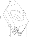
- FIG. 1 It is a perspective view of the cutting insert of an embodiment. It is a perspective view which looked at the cutting insert shown in FIG. 1 from another direction. It is a top view of the cutting insert shown in FIG. 1 as viewed from the A1 direction shown in FIG.
- FIG. 3 is a side view of the cutting insert shown in FIG. 1 as viewed from the A2 direction shown in FIG. It is an enlarged view of the region B1 shown in FIG. It is an enlarged view of the area B2 shown in FIG. It is an enlarged view of the area B3 shown in FIG. It is explanatory drawing which shows the variation of the shape of the 2nd side surface and the 3rd ridge line in the cutting part of the cutting insert shown in FIG.
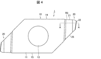
- FIG. 4 is a cross-sectional view taken along the line AA of FIG. It is a perspective view which shows the cutting tool of an embodiment. It is an enlarged view of the region B4 shown in FIG.
- It is a schematic diagram which shows one process of the manufacturing method of the machined work of embodiment. It is a schematic diagram which shows one process of the manufacturing method of the machined work of embodiment. It is a schematic diagram which shows one process of the manufacturing method of the machined work of embodiment. It is a schematic diagram which shows one process of the manufacturing method of the machined work of embodiment. It is a schematic diagram which shows one process of the manufacturing method of the machined work of embodiment.
- a method for manufacturing a cutting insert (hereinafter, also simply referred to as an insert), a cutting tool, and a cutting work according to an embodiment of the present disclosure will be described in detail with reference to the drawings.
- inserts and cutting tools may include any components not shown in each referenced figure.
- the dimensions of the members in each drawing do not faithfully represent the dimensions of the actual constituent members, the dimensional ratio of each member, and the like.
- FIG. 1 is a perspective view of the insert 1.
- FIG. 2 is a perspective view of the insert 1 as viewed from another direction.
- FIG. 3 is a top view of the insert 1 as viewed from the A1 direction shown in FIG.
- FIG. 4 is a side view of the insert 1 as viewed from the A2 direction shown in FIG.
- the insert 1 includes a base portion 10 and a cutting portion 20 provided so as to protrude from the base portion 10.
- the substrate portion 10 can be used as a portion restrained by the holder 105 when the insert 1 is attached to the holder 105 (see FIGS. 10 and 11) described later.
- the cutting portion 20 is a portion that comes into contact with the work material 201 (see FIGS. 12 to 14) to be machined in the cutting process described later, and is a portion that plays a main role in the cutting process.
- the insert 1 includes two cutting portions 20, but may include three or more cutting portions 20, or may include only one cutting portion 20.
- the shape of the substrate portion 10 is not limited to a specific configuration.
- the shape of the substrate portion 10 may be a rod shape, a polygonal plate shape, or a polygonal prism shape.
- the substrate portion 10 has a hexagonal plate shape in which two opposing corners of a rectangle are dropped.
- the substrate portion 10 is located on the opposite side of the first main surface 11 (see FIG. 1), which is hexagonal, and the second main surface 12 (see FIG. 2), which is also hexagonal. It has a through hole 13 that opens at the center of the first main surface 11 and the center of the second main surface 12.
- the through hole 13 may be used to fix the insert 1 to the holder 105 (see FIGS. 10 and 11) described later.
- the insert 1 can be fixed to the holder 105 by inserting a screw 107 into the through hole 13.
- the substrate portion 10 has an upper side surface 14 and a lower side surface 15.
- the upper side surface 14 and the lower side surface 15 are flat surfaces, respectively, and are located parallel to each other along the longitudinal direction of the insert 1. As shown in FIGS. 1 and 2, the upper side surface 14 and the lower side surface 15 form a part of the side surface portion located between the first main surface 11 and the second main surface 12 in the substrate portion 10. good.
- flat or “flat surface” is intended to be not a curved surface at a visible level, or to have no visible unevenness, and is strictly flat. Do not ask to be. Therefore, unevenness to an unavoidable degree may be allowed in the manufacture of the insert 1. Specifically, it may have irregularities with a surface roughness of about 50 ⁇ m.
- the size of the substrate portion 10 is not particularly limited.
- the maximum width of the substrate portion 10 in the direction from the first main surface 11 to the second main surface 12 orthogonal to the longitudinal direction of the insert 1 may be set to, for example, about 2.9 to 4.1 mm. Further, the dimension of the substrate portion 10 in the longitudinal direction may be set to, for example, about 8 to 20 mm.
- the shape of the two cutting portions 20 is not limited to a specific configuration.
- the cutting portion 20 may have, for example, a rod shape, a polygonal plate shape, or a polygonal prism shape.
- the shape of the two cutting portions 20 in this example is a square plate shape in which one corner of a triangle is dropped.
- the substrate portion 10 and the cutting portion 20 in the insert 1 may be formed separately or integrally.
- the width of the cutting portion 20 in the direction from the first main surface 11 orthogonal to the longitudinal direction of the insert 1 toward the second main surface 12 may be smaller than the width of the base portion 10 in the same direction.
- the width of the base portion 10 is relatively large, the wall thickness of the base portion 10 is secured, so that the insert 1 can be stably fixed to the holder 105 (see FIGS. 10 and 11). ..
- the width of the cutting portion 20 is relatively small, the degree of freedom in the cutting width of the work material 201 in the cutting process can be increased.
- the widths of the base portion 10 and the cutting portion 20 are different as described above, the regions of the base portion 10 and the cutting portion 20 in the insert 1 may be divided by the portions having different widths.
- the two cutting portions 20 each project outward from the base portion 10.
- One of the two cutting portions 20 projects outward from one end in the longitudinal direction of the substrate portion 10 along the longitudinal direction.
- the other cutting portion 20 of the two cutting portions 20 projects along the longitudinal direction from the other end portion in the longitudinal direction of the substrate portion 10.
- the two cutting portions 20 project to the opposite sides of each other.
- the two cutting portions 20 may be positioned so as to be rotationally symmetric with respect to the central axis of the through hole 13.
- the two cutting portions 20 project toward opposite sides and are positioned so as to be rotationally symmetric with respect to the central axis of the through hole 13, and have substantially the same configuration as each other. Therefore, in the following, of the two cutting portions 20, in FIG. 1, the configuration of the cutting portion 20 protruding toward the right side when the insert 1 is viewed from the side of the first main surface 11 of the base portion 10 will be described in detail. The description of the other cutting portion 20 protruding toward the left side will be omitted.
- FIG. 5 is an enlarged view of the region B1 shown in FIG.
- FIG. 6 is an enlarged view of the region B2 shown in FIG.
- FIG. 7 is an enlarged view of the region B3 shown in FIG.
- the cutting portion 20 has an upper surface 21, a tip surface 22, a first side surface 23, a second side surface 24, and a lower surface 25.
- the tip surface 22 is located on the side of the tip in the direction in which the cutting portion 20 protrudes from the base portion 10.
- the upper surface 21 extends from the substrate portion 10 to the tip surface 22 and is adjacent to the tip surface 22. In the case of the other cutting portion 20, the upper surface 21 extends from the lower side surface 15 of the base portion 10 to the tip surface 22.
- the first side surface 23 extends from the base portion 10 to the tip surface 22. More specifically, the first side surface 23 extends from the second main surface 12 of the substrate portion 10 to the tip surface 22. In the other cutting portion 20, the first side surface 23 extends from the second main surface 12 of the base portion 10 to the tip surface 22. The first side surface 23 is adjacent to the upper surface 21 and is also adjacent to the tip surface 22.
- the second side surface 24 extends from the base portion 10 to the tip surface 22. More specifically, the second side surface 24 extends from the stepped surface 16 adjacent to the first main surface 11 of the substrate portion 10 to the tip surface 22.
- the step surface 16 is a plane extending in the direction from the first main surface 11 to the second main surface 12.
- the stepped surface 16 is a surface generated when the width of the cutting portion 20 in the direction from the first main surface 11 to the second main surface 12 is smaller than the width of the base portion 10 in the same direction.
- the second side surface 24 is adjacent to the first main surface 11 of the base portion 10, and is the tip from the stepped surface forming a plane in the direction from the first main surface 11 to the second main surface 12. It extends toward the surface 22.
- the second side surface 24 is adjacent to the upper surface 21 on the opposite side of the first side surface 23. Further, the second side surface 24 is adjacent to the tip surface 22 on the opposite side of the first side surface 23.
- the lower surface 25 extends from the lower side surface 15 of the substrate portion 10 to the tip surface 22. In the case of the other cutting portion 20, the lower surface 25 extends from the upper side surface 14 of the base portion 10 to the tip surface 22. The lower surface 25 is adjacent to the upper surface 21 via the first side surface 23, the tip surface 22, and the second side surface 24.
- the tip surface 22 and the first side surface 23 each have a substantially planar shape.
- the tip surface 22 and the first side surface 23 may be directly connected to each other, but a curved surface connecting the two planes may be located between the tip surface 22 and the first side surface 23.
- the second side surface 24 has a portion having a convex curved surface shape, and the shape of the second side surface 24 will be described later.
- the tip surface 22 and the first side surface 23 may have a curved surface shape.
- the tip surface 22 may be composed of one plane as long as it has a substantially planar shape, or may be composed of a plurality of planes slightly inclined to each other.
- the tip surface 22 is composed of two planes.
- the first side surface 23 may be composed of one plane, or may be composed of a plurality of planes slightly inclined with each other.
- the second side surface 23 is composed of one plane.
- a ridgeline is formed at the intersection of the surfaces such as the upper surface 21, the tip surface 22, the first side surface 23, and the second side surface 24.
- the ridgeline where the upper surface 21 and the tip surface 22 intersect is the first ridgeline R1
- the ridgeline where the upper surface 21 and the first side surface 23 intersect is the second ridgeline R2
- the ridgeline where the upper surface 21 and the second side surface 24 intersect is the third ridgeline (ridgeline). ) R3.
- the cutting portion 20 has a first ridge line R1, a second ridge line R2, and a third ridge line R3. Cutting edges for cutting can be formed on these ridges and are located on these ridges.
- the cutting portion 20 has a first cutting edge C1 on the first ridge line R1 and a second cutting edge C2 on the second ridge line R2.
- the third ridge line R3 does not have a cutting edge and has a portion forming a convex curve when viewed from the upper surface 21 side, and the shape of the third ridge line R3 will be described later.
- the first cutting edge C1 is located at least a part of the first ridge line R1.
- the first cutting edge C1 may be located on the entire first ridge line R1, or may be located only on a part of the first ridge line R1.
- the first cutting edge C1 is located on the entire first ridge line R1.
- the first cutting edge C1 is a wiper blade protruding toward the work material 201 (see FIGS. 12 to 14).
- the wiper blade may be paraphrased as a shaving blade.
- the second cutting edge C2 is located at least a part of the second ridge line R2.
- the second cutting edge C2 may be located on the entire second ridge line R2, or may be located only on a part of the second ridge line R2.
- the second cutting edge C2 is located on the entire second ridge line R2 and is connected to the first cutting edge C1.
- the first cutting edge C1 and the second cutting edge C2 pass through the ridgeline where the curved surface and the upper surface 21 intersect. It may be connected.
- the ridgeline where the curved surface and the upper surface 21 intersect may form a part of the cutting edge.
- the tip surface 22 and the first side surface 23 have a substantially planar shape. Therefore, the first cutting edge C1 and the second cutting edge C2 also have a substantially linear shape, respectively.
- the first cutting edge C1 can be used as a cutting edge that mainly functions in, for example, grooving and parting off.
- the second cutting edge C2 may be used as a cutting edge that assists the cutting process by the first cutting edge C1.
- the second cutting edge C2 can be used, for example, as a cutting edge that mainly functions in post-grinding processing (lateral feed processing).
- the first cutting edge C1 may be used as a cutting edge that assists the cutting process by the second cutting edge C2.
- the upper surface 21 has an uneven shape rather than a planar shape as shown in FIGS. 5 and 6. Specifically, as shown in FIG. 7, in this example, the upper surface 21 has a first inclined surface 21a, a second inclined surface 21b, a flat bottom surface 21c, and a breaker protrusion 21d.
- the first inclined surface 21a has an inclination extending along the first cutting edge C1 (first ridge line R1) and descending toward the bottom surface 21c.
- the second inclined surface 21b has an inclination extending along the second cutting edge C2 (second ridge line R2) and descending toward the bottom surface 21c. 5 to 7 show the first inclined surface 21a and the second inclined surface 21b with hatching.
- the breaker protrusion 21d extends along the third ridge line R3 and rises from the bottom surface 21c toward the second side surface 24.
- the third ridge line R3 is located at the upper end of the breaker protrusion 21d.
- the breaker protrusion 21d has a function of controlling the traveling direction of chips generated in the first cutting edge C1 and the second cutting edge C2 and flowing through the upper surface 21. By bringing the chips into contact with the breaker protrusion 21d, the chips can be curled and the chip dischargeability can be improved.
- the breaker protrusion 21d has a convex shape toward the intersection of the first ridge line R1 and the second ridge line R2 when viewed from the side of the upper surface 21.
- the breaker protrusion 21d has the above-mentioned shape, it is possible to secure the thickness of the breaker protrusion 21d on the tip side while ensuring the space for the chips generated by the second cutting edge C2 on the upper surface 21 to flow. Thereby, both the chip discharge property and the durability of the insert 1 can be improved.
- FIG. 8 is an explanatory view showing variations in the shapes of the second side surface 24 and the third ridge line R3 with emphasis on curves and slopes, and is viewed from the side of the upper surface 21.
- FIG. 9 is a cross-sectional view taken along the line AA of FIG.
- the second side surface 24 of the cutting portion 20 has a first surface region 24-1 located on the side of the tip surface 22 and a first surface region 24-1. It has a second surface region 24-2 located farther from the tip surface 22 than the surface region 24-1.
- the first surface region 24-1 has a convex curved surface shape, and the portion corresponding to the first surface region 24-1 of the third ridge line R3 when viewed from the side of the upper surface 21 is a convex curve. ..
- the third ridge line when the second side surface 24 has an overall planar shape and is viewed from the side of the upper surface 21 By making the shapes of the second side surface 24 and the third ridge line R3 the above-mentioned shape, for example, the third ridge line when the second side surface 24 has an overall planar shape and is viewed from the side of the upper surface 21.
- the thickness of the cutting portion 20 can be increased as compared with the case where R3 is a straight line as a whole.
- the first surface region 24-1 has a planar shape and the first surface region 24-1 of the third ridge line R3 when viewed from the side of the upper surface 21 is a straight line
- the thickness of the tip portion of the first cutting edge C1 in 20 can be increased.
- the increased thickness makes it stronger against bending force, so that the strength of the insert 1 is improved and it becomes difficult to bend.
- the insert 1 since the insert 1 is less likely to bend, its function is stable as a wiper blade of the first cutting blade C1. Therefore, the surface accuracy of the machined surface is improved.
- the second ridge line has a substantially linear shape, and the flank surface where the intersection with the rake face becomes the second ridge line is formed flat. Therefore, in the tip described in Patent Document 1, the strength of the cut portion may be insufficient.
- the width of the cutting portion is smaller than the width of the base portion.
- a configuration in which the width of the cutting portion is smaller than the width of the base portion has an advantage that the degree of freedom in the machining width in cutting can be increased, but the strength is lowered due to the thin thickness of the cutting portion. With the above configuration, it is possible to realize an insert having a high degree of freedom in the machining width in cutting and having excellent durability.
- the portion corresponding to the first surface region 24-1 of the third ridge line R3 forming a convex curve when viewed from the side of the upper surface 21 is the tip end.
- the configuration is such that the surface 22 approaches the first side surface 23 as it moves toward the substrate portion 10.
- the above-mentioned “configuration approaching the first side surface 23” is not necessarily limited to a configuration in which the distance from the first side surface 23 is narrowed.
- the portion of the third ridge line R3 corresponding to the first surface region 24-1 may be inclined toward the first side surface 23. For example, as shown by reference numeral 1002 in FIG.
- the convex curve of the portion corresponding to the first surface region 24-1 of the third ridge line R3 is the connection portion with the tip surface 22.
- P1 is the closest to the virtual plane n including the first main surface 11 of the substrate portion 10. Then, as it moves away from the connection portion P1 and toward the base portion 10, it moves away from the virtual plane n and approaches the first side surface 23.
- grooving and parting off are performed as compared with the configuration in which the portion corresponding to the first surface region 24-1 of the third ridge line R3 forming the convex curve shown by reference numeral 1001 in FIG. 8 is a convex curve.
- the first surface region 24-1 is unlikely to come into contact with the machined surface. Therefore, the surface accuracy of the machined surface is improved.
- the portion corresponding to the second surface region 24-2 of the third ridge line R3 when viewed from the side of the upper surface 21, is also separated from the tip surface 22 to the substrate portion 10. It may be configured to approach the first side surface 23 as it goes toward it.
- the convex curve of the portion corresponding to the second surface region 24-2 of the third ridge line R3 when viewed from the side of the upper surface 21, is the first surface region 24-1.
- the boundary portion P2 is closest to the virtual plane n including the first main surface 11 of the base portion 10. Then, as it approaches the substrate portion 10 away from the boundary portion P2, it separates from the virtual plane n and approaches the first side surface 23.
- the third ridge line R3 The portion corresponding to the second surface region 24-2 may be a convex curve. Further, the radius of curvature of the convex curve of the portion corresponding to the second surface region 24-2 may be larger than the radius of curvature of the convex curve of the portion corresponding to the first surface region 24-1.
- Reference numeral 1004 shows a configuration in which the above configuration is adopted for the configuration of reference numeral 1003 in FIG.
- the first surface region 24-1 and the second surface region 24-2 are connected to each other (in other words, the first of the third ridge line R3).
- the portion corresponding to the surface region 24-1 and the portion corresponding to the second surface region 24-2 are connected to each other) have a concave shape.
- the portions where the first surface region 24-1 and the second surface region 24-2 are connected to each other are smoothly connected. That is, in the configuration shown in FIG. 9, the portion of the second side surface 24 composed of the first surface region 24-1 and the second surface region 24-2 has a convex shape as a whole. In this case, the load applied to the second side surface 24 is unlikely to be concentrated on a specific location. Therefore, the configuration shown in FIG. 9 has higher durability than the configurations shown by reference numerals 1001 to 1003 in FIG.
- the second side surface 24 is further located on the third surface region 24-which is located further away from the tip surface 22 than the second surface region 24-2.
- the third surface region 24-3 has a concave curved surface shape, and when viewed from the side of the upper surface 21, the portion of the third ridge line R3 corresponding to the third surface region 24-3 is concave. It can also be configured to be a curve.
- the portion corresponding to the third surface region 24-3 corresponds to the connection portion between the stepped surface 16 of the substrate portion 10 and the second side surface 24, and is the third.
- the portion of the ridge line R3 corresponding to the third surface region 24-3 forms a concave curve when viewed from the side of the upper surface 21.
- the third surface region 24-3 has a concave curved surface shape.
- the stress applied to the root of the cutting portion 20 can be reduced, and the insert 1 can be configured to be less likely to be damaged.
- the portion corresponding to the second surface region 24-2 rather than the radius of curvature of the concave curve of the portion corresponding to the third surface region 24-3 in the third ridge line R3.
- the radius of curvature of the convex curve of is also large.
- the insert 1 can be stably fixed to the holder 105 while deep grooving can be performed.
- insert 1 examples include inorganic materials such as cemented carbide, cermet and ceramics.
- inorganic materials such as cemented carbide, cermet and ceramics.
- composition of the cemented carbide include WC (tungsten carbide) -Co, WC-TiC (titanium carbide) -Co and WC-TiC-TaC (tantalum carbide) -Co.
- Cermet is a sintered composite material in which a metal is composited with a ceramic component.
- examples of the cermet include compounds containing TiC or TiN (titanium nitride) as a main component. Needless to say, the material of the insert 1 is not limited to these.
- the insert 1 may be configured to include a main body containing the above-mentioned material and a coating layer covering the main body.
- the material of the coating layer include carbides of titanium, nitrides, oxides, carbonic acid oxides, nitrogen oxides, carbonitrides and carbonic acid nitrogen oxides.
- the coating layer may contain only one of the above materials, or may contain a plurality of the above materials.
- the covering layer may be composed of only one layer, or may be a structure in which a plurality of layers are laminated. The material of the coating layer is not limited to these.
- the coating layer can be positioned on the substrate by using a chemical vapor deposition (CVD) method or a physical vapor deposition (PVD) method.
- CVD chemical vapor deposition
- PVD physical vapor deposition
- the coating layer is formed by using the above vapor deposition method while the substrate is held on the inner peripheral surface of the through hole 13, the entire surface of the substrate excluding the inner peripheral surface of the through hole 13 is covered.
- the coating layer can be located on.
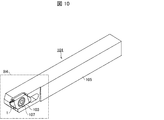
- FIG. 10 is a perspective view showing the cutting tool 101 of the embodiment.
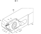
- FIG. 11 is an enlarged view of the region B4 shown in FIG.
- the cutting tool 101 of the embodiment is a rod-shaped tool having an insert 1 on the tip side.
- the cutting tool 101 includes a rod-shaped holder 105 having a pocket 103 on the tip end side, and the above-mentioned insert 1 located in the pocket 103.
- the pocket 103 is a portion to which the insert 1 is mounted, and has a seating surface and a restraining side surface inclined with respect to the seating surface. Further, the pocket 103 is open on the tip end side of the holder 105.
- the insert 1 is mounted so that a portion used as a cutting edge in the cutting portion 20, that is, at least a part of the above-mentioned first cutting edge C1 and second cutting edge C2 protrudes outward from the holder 105.
- the upper side surface 14 of the base portion 10 is the upper end of the insert 1
- the lower side surface 15 of the base portion 10 is the lower end of the insert 1.
- the insert 1 is attached to the holder 105 by a screw 107.
- the base portion 10 of the insert 1 and the pocket 103 may be in direct contact with each other, and a sheet or the like is interposed between the insert 1 and the pocket 103. You may.
- Steel, cast iron, etc. are used as the material of the holder 105.
- the toughness of the holder 105 can be increased.
- Such a cutting tool 101 is used for so-called turning and can be used for post-grinding.
- the cutting tool 101 is not limited to post-grinding, and can also be used for, for example, inner diameter machining, outer diameter machining, and grooving.
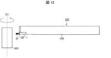
- FIGS. 12 to 15 are schematic views showing one step of a method for manufacturing a machined product according to an embodiment. 12 to 15 show a state in which the cutting tool 101 to which the insert 1 is mounted is viewed from the side of the upper surface 21 of the cutting portion 20.
- the work piece is produced by cutting the work material 201.
- the method for manufacturing a machined product according to an embodiment includes the following steps. That is, (1) The process of rotating the work material 201 and (2) The process of bringing the cutting tool 101 into contact with the rotating work material 201, (3) A step of separating the cutting tool 101 from the work material 201 is provided.
- the work material 201 is rotated around the shaft O1 and the cutting tool 101 is relatively close to the work material 201.
- the first cutting edge C1 and the second cutting edge C2, which are the cutting edges of the cutting tool 101 are brought into contact with the work material 201 to cut the work material 201.
- the cutting tool 101 moves relative to the rotating work material 201 in the axial direction of the shaft O1.
- the work material 201 is cut.
- the second cutting edge C2 faces forward in the moving direction.
- the cutting tool 101 is relatively far from the work material 201.
- the cutting tool 101 is moved closer to the work material 201 while the shaft O1 is fixed and the work material 201 is rotated around the shaft O1. Further, in the examples of FIGS. 13 and 14, the work material 201 is cut by bringing the cutting edge of the insert 1 into contact with the rotating work material 201. Further, in FIG. 15, the cutting tool 101 is moved away from the work material 201 in a rotated state.
- the cutting tool 101 is brought into contact with the work material 201 or the cutting tool 101 is separated from the work material 201 by moving the cutting tool 101 in each step.
- the cutting tool 101 is not limited to such a form.
- the work material 201 may be brought closer to the cutting tool 101.
- the work material 201 may be moved away from the cutting tool 101.
- the process of keeping the work material 201 rotated and bringing the cutting edge of the insert 1 into contact with different parts of the work material 201 may be repeated.
- typical examples of the material of the work material 201 include carbon steel, alloy steel, stainless steel, cast iron, non-ferrous metal and the like.
Landscapes
- Engineering & Computer Science (AREA)
- Mechanical Engineering (AREA)
- Cutting Tools, Boring Holders, And Turrets (AREA)
Priority Applications (1)
| Application Number | Priority Date | Filing Date | Title |
|---|---|---|---|
| JP2022521917A JP7344376B2 (ja) | 2020-05-11 | 2021-05-11 | 切削インサート、切削工具および切削加工物の製造方法 |
Applications Claiming Priority (2)
| Application Number | Priority Date | Filing Date | Title |
|---|---|---|---|
| JP2020-083381 | 2020-05-11 | ||
| JP2020083381 | 2020-05-11 |
Publications (1)
| Publication Number | Publication Date |
|---|---|
| WO2021230219A1 true WO2021230219A1 (ja) | 2021-11-18 |
Family
ID=78524386
Family Applications (1)
| Application Number | Title | Priority Date | Filing Date |
|---|---|---|---|
| PCT/JP2021/017792 Ceased WO2021230219A1 (ja) | 2020-05-11 | 2021-05-11 | 切削インサート、切削工具および切削加工物の製造方法 |
Country Status (2)
| Country | Link |
|---|---|
| JP (1) | JP7344376B2 (https=) |
| WO (1) | WO2021230219A1 (https=) |
Citations (5)
| Publication number | Priority date | Publication date | Assignee | Title |
|---|---|---|---|---|
| JPH02145903U (https=) * | 1989-05-12 | 1990-12-11 | ||
| JPH09314407A (ja) * | 1996-05-29 | 1997-12-09 | Mitsubishi Materials Corp | スローアウェイチップ |
| JPH1133803A (ja) * | 1997-07-23 | 1999-02-09 | Sumitomo Electric Ind Ltd | スローアウェイチップ |
| WO2015129836A1 (ja) * | 2014-02-26 | 2015-09-03 | 京セラ株式会社 | 切削インサートおよび切削工具並びに切削加工物の製造方法 |
| JP2019104088A (ja) * | 2017-12-13 | 2019-06-27 | 株式会社タンガロイ | 後挽き加工用の切削インサート |
-
2021
- 2021-05-11 JP JP2022521917A patent/JP7344376B2/ja active Active
- 2021-05-11 WO PCT/JP2021/017792 patent/WO2021230219A1/ja not_active Ceased
Patent Citations (5)
| Publication number | Priority date | Publication date | Assignee | Title |
|---|---|---|---|---|
| JPH02145903U (https=) * | 1989-05-12 | 1990-12-11 | ||
| JPH09314407A (ja) * | 1996-05-29 | 1997-12-09 | Mitsubishi Materials Corp | スローアウェイチップ |
| JPH1133803A (ja) * | 1997-07-23 | 1999-02-09 | Sumitomo Electric Ind Ltd | スローアウェイチップ |
| WO2015129836A1 (ja) * | 2014-02-26 | 2015-09-03 | 京セラ株式会社 | 切削インサートおよび切削工具並びに切削加工物の製造方法 |
| JP2019104088A (ja) * | 2017-12-13 | 2019-06-27 | 株式会社タンガロイ | 後挽き加工用の切削インサート |
Also Published As
| Publication number | Publication date |
|---|---|
| JP7344376B2 (ja) | 2023-09-13 |
| JPWO2021230219A1 (https=) | 2021-11-18 |
Similar Documents
| Publication | Publication Date | Title |
|---|---|---|
| US10010939B2 (en) | Cutting insert, cutting tool, and method for manufacturing machined product | |
| JP6612900B2 (ja) | インサート、切削工具及び切削加工物の製造方法 | |
| CN111902232B (zh) | 切削刀片、切削工具及切削加工物的制造方法 | |
| US12521797B2 (en) | Cutting insert, cutting tool, and method for manufacturing machined product | |
| JP7093784B2 (ja) | 切削インサート、切削工具及び切削加工物の製造方法 | |
| WO2019087844A1 (ja) | 切削インサート、切削工具及び切削加工物の製造方法 | |
| JP6847230B2 (ja) | 切削インサート、切削工具及び切削加工物の製造方法 | |
| WO2020203414A1 (ja) | 切削インサート、旋削工具及び切削加工物の製造方法 | |
| JP6882473B2 (ja) | 切削インサート、切削工具及び切削加工物の製造方法 | |
| JP7325510B2 (ja) | 切削インサート、切削工具及び切削加工物の製造方法 | |
| WO2021095520A1 (ja) | 切削インサート、切削工具及び切削加工物の製造方法 | |
| JP7344376B2 (ja) | 切削インサート、切削工具および切削加工物の製造方法 | |
| JPWO2020090738A1 (ja) | 切削インサート、切削工具及び切削加工物の製造方法 | |
| KR102540681B1 (ko) | 절삭 인서트, 절삭 공구 및 절삭 가공물의 제조 방법 | |
| JP7455964B2 (ja) | 切削インサート、切削工具および切削加工物の製造方法 | |
| WO2022118946A1 (ja) | 切削インサート、切削工具及び切削加工物の製造方法 | |
| US20250222528A1 (en) | Cutting insert, cutting tool, and method for manufacturing machined product | |
| JP7344385B2 (ja) | 切削インサート、切削工具及び切削加工物の製造方法 | |
| JP7204882B2 (ja) | 切削インサート、切削工具及び切削加工物の製造方法 | |
| JP7239480B2 (ja) | 切削インサート、切削工具及び切削加工物の製造方法 | |
| JP2024057855A (ja) | 切削インサート、切削工具及び切削加工物の製造方法 | |
| JPWO2020066958A1 (ja) | 切削インサート、切削工具及び切削加工物の製造方法 |
Legal Events
| Date | Code | Title | Description |
|---|---|---|---|
| 121 | Ep: the epo has been informed by wipo that ep was designated in this application |
Ref document number: 21803243 Country of ref document: EP Kind code of ref document: A1 |
|
| ENP | Entry into the national phase |
Ref document number: 2022521917 Country of ref document: JP Kind code of ref document: A |
|
| NENP | Non-entry into the national phase |
Ref country code: DE |
|
| 122 | Ep: pct application non-entry in european phase |
Ref document number: 21803243 Country of ref document: EP Kind code of ref document: A1 |