WO2021225062A1 - ケーブル牽引端末構造 - Google Patents
ケーブル牽引端末構造 Download PDFInfo
- Publication number
- WO2021225062A1 WO2021225062A1 PCT/JP2021/015297 JP2021015297W WO2021225062A1 WO 2021225062 A1 WO2021225062 A1 WO 2021225062A1 JP 2021015297 W JP2021015297 W JP 2021015297W WO 2021225062 A1 WO2021225062 A1 WO 2021225062A1
- Authority
- WO
- WIPO (PCT)
- Prior art keywords
- inner tube
- optical cable
- terminal structure
- tube
- outer tube
- Prior art date
- Legal status (The legal status is an assumption and is not a legal conclusion. Google has not performed a legal analysis and makes no representation as to the accuracy of the status listed.)
- Ceased
Links
Images





Classifications
-
- G—PHYSICS
- G02—OPTICS
- G02B—OPTICAL ELEMENTS, SYSTEMS OR APPARATUS
- G02B6/00—Light guides; Structural details of arrangements comprising light guides and other optical elements, e.g. couplings
- G02B6/46—Processes or apparatus adapted for installing or repairing optical fibres or optical cables
- G02B6/50—Underground or underwater installation; Installation through tubing, conduits or ducts
- G02B6/54—Underground or underwater installation; Installation through tubing, conduits or ducts using mechanical means, e.g. pulling or pushing devices
- G02B6/545—Pulling eyes
-
- G—PHYSICS
- G02—OPTICS
- G02B—OPTICAL ELEMENTS, SYSTEMS OR APPARATUS
- G02B6/00—Light guides; Structural details of arrangements comprising light guides and other optical elements, e.g. couplings
- G02B6/44—Mechanical structures for providing tensile strength and external protection for fibres, e.g. optical transmission cables
- G02B6/4401—Optical cables
- G02B6/4429—Means specially adapted for strengthening or protecting the cables
- G02B6/443—Protective covering
- G02B6/4431—Protective covering with provision in the protective covering, e.g. weak line, for gaining access to one or more fibres, e.g. for branching or tapping
-
- G—PHYSICS
- G02—OPTICS
- G02B—OPTICAL ELEMENTS, SYSTEMS OR APPARATUS
- G02B6/00—Light guides; Structural details of arrangements comprising light guides and other optical elements, e.g. couplings
- G02B6/44—Mechanical structures for providing tensile strength and external protection for fibres, e.g. optical transmission cables
- G02B6/4401—Optical cables
- G02B6/4429—Means specially adapted for strengthening or protecting the cables
- G02B6/44384—Means specially adapted for strengthening or protecting the cables the means comprising water blocking or hydrophobic materials
-
- G—PHYSICS
- G02—OPTICS
- G02B—OPTICAL ELEMENTS, SYSTEMS OR APPARATUS
- G02B6/00—Light guides; Structural details of arrangements comprising light guides and other optical elements, e.g. couplings
- G02B6/46—Processes or apparatus adapted for installing or repairing optical fibres or optical cables
- G02B6/50—Underground or underwater installation; Installation through tubing, conduits or ducts
Definitions
- the present invention relates to a cable tow terminal structure.
- the present application claims priority for US Patent Application No. 63/021100, which was provisionally filed in the United States on May 07, 2020, the contents of which are incorporated herein by reference.
- the cable traction terminal structure described in Patent Document 1 includes a flexible pipe formed by spirally connecting molded members having a substantially groove-shaped cross section, and a metal net body covering the outer peripheral surface of the flexible pipe. It is provided with a heat-shrinkable tube that covers the outer peripheral surface of the metal mesh. This heat shrinkable tube prevents water from entering the inner tube.
- the present invention has been made in consideration of such circumstances, and an object of the present invention is to provide a cable traction terminal structure capable of preventing water from entering the inner tube.
- the traction terminal structure according to the first aspect of the present invention can accommodate an optical cable inside, and is provided on an inner tube formed by spirally winding and connecting strands and an outer peripheral surface of the inner tube.
- a flexible outer tube is provided, and a part of the outer tube has entered the inside of a groove formed on the outer peripheral surface of the inner tube.
- the outer tube in the groove follows the bending of the inner tube even when a force for bending the inner tube is applied.
- it is possible to alleviate the occurrence of irregularities on the outer peripheral surface of the outer tube. Therefore, since cracks are less likely to occur on the outer peripheral surface of the inner tube, it is possible to prevent water from entering the inner tube.
- a connecting member may be provided on the outer peripheral surface of the rear end of the inner tube.
- a protrusion may be formed on the inner wall of the connecting member, and the protrusion may be fitted into the groove of the inner tube.
- the connecting member may be overlapped with the rear end of the inner tube and may be overlapped with the rear end of the outer tube.
- the connecting member may be adhered at least at an overlapping portion overlapped with the rear end of the outer tube.
- the connecting member may have a recess formed at a position facing the outer tube, and an adhesive may be provided in the recess.
- a gap may be provided between the outer tube and the connecting member in the longitudinal direction of the inner tube, and a water blocking member may be provided in the gap.
- the water blocking member may be a resin material.
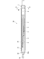
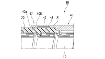
- FIG. 1 is a cross-sectional view taken along the line II-II of FIG. It is sectional drawing of the main part of the rear end of the optical cable tow terminal structure which concerns on 1st Embodiment. It is an exploded view at the rear end of the optical cable tow terminal structure which concerns on 1st Embodiment. It is sectional drawing of the main part in the overlapping part of a connecting member and an inner tube. It is sectional drawing of the main part of the modification of the optical cable traction terminal structure which concerns on 1st Embodiment.
- the optical cable traction terminal structure 1A includes an inner tube 10, an outer tube 20, a cone-shaped head 30, and a connecting member 40.
- the longitudinal direction of the optical cable traction terminal structure 1A is simply referred to as the longitudinal direction.
- the front end side of the optical cable traction terminal structure 1A provided with the head 30 may be referred to as a front end
- the base end side of the optical cable traction terminal structure 1A provided with a connecting member 40 may be referred to as a rear end.
- the direction intersecting the central axis O (see FIG. 3) of the optical cable traction terminal structure 1A is referred to as a radial direction.
- a cross section orthogonal to the central axis O is referred to as a cross section.
- the optical cable traction terminal structure 1A of the present embodiment further includes an optical cable 2, a pair of tension members 3, and a holder 4.
- the head 30 is provided on the tip end side of the optical cable traction terminal structure 1A, and the connecting member 40 is provided on the proximal end side of the optical cable traction terminal structure 1A.
- the head 30 is a metal member, and as shown in FIG. 1, has a pooling eye 31 at its tip.
- the head 30 is joined to the inner tube 10 by welding, for example.
- the head 30 has an inclined portion 30a.
- the inclined portion 30a is configured so that the outer diameter gradually decreases from the base end to the tip end.
- a pooling eye 31 is arranged at the tip of the inclined portion 30a.
- the optical cable 2 is housed inside the inner tube 10.
- 3456 core optical fibers 5 are bundled, and a connector 6 is terminated in each optical fiber 5.
- a pair of tension members 3 are provided so as to sandwich the optical cable 2 in the radial direction in a cross-sectional view (four in total).
- the tension member 3 functions as a member that receives a force such as tensile stress generated when the optical cable traction terminal structure 1A is towed.
- the number of tension members is set to 4, but the number is not limited to this.
- the holder 4 is made of a tubular metal having a through hole 4a through which the optical cable 2 is inserted.
- the holder 4 is fixed to the inner tube 10 by bolts 7 via a connecting member 40.
- the holder 4 has a tension member fixing portion (not shown) for fixing the tension member 3 on the inner peripheral surface of the through hole 4a.
- the inner tube 10 is configured as a tubular member (spiral tube) formed by spirally winding a tape-shaped wire (for example, a stainless (SUS) plate) 10A and connecting them in the longitudinal direction.
- a tape-shaped wire for example, a stainless (SUS) plate
- the strands 10A are fitted by about 1/3 in the width direction and connected in a spiral shape.
- the optical cable 2 is not shown in FIG. 3 in order to make the drawing easier to see.
- FIG. 4 is an exploded view of the rear end of the optical cable tow terminal structure according to the first embodiment. As shown in FIG.
- a groove 11 is formed in the central portion in the width direction along the longitudinal direction of the strand 10A.
- the distance between the grooves 11 adjacent to each other in the longitudinal direction is formed by the groove pitch P1.
- the outer tube 20 is provided on the outer peripheral surface of the inner tube 10 and has flexibility. A part of the outer tube 20 has entered the inside of the groove 11 formed on the outer peripheral surface of the inner tube 10. That is, the groove 11 is filled with a part of the outer tube 20. Further, the outer tube 20 is not provided on the outer peripheral surface of the rear end 12 of the inner tube 10.
- the material of the outer tube 20 is, for example, an elastic body such as polyvinyl chloride, polyolefin resin, fluoropolymer, or thermoplastic elastomer. As a result, even if the inner tube 10 is bent, the resilience to the linear state is improved.
- the method of inserting a part of the outer tube 20 into the groove 11 of the inner tube 10 is not particularly limited.
- the polyolefin resin is inserted into the groove 11 of the inner tube 10. Let me. Then, the liquid polyolefin resin is brought into close contact with the inner surface of the groove 11 and cured to have elastic force.
- a connecting member 40 is provided on the outer peripheral surface of the rear end 12 of the inner tube 10.
- the connecting member 40 has a cylindrical shape. Inside the connecting member 40, in order from the rear end 40A side, an inner peripheral surface 41, a first recess 42 recessed with respect to the inner peripheral surface 41, and a second recess 43 recessed with respect to the first recess 42. Is formed. The inner diameter of the first recess 42 and the inner diameter of the second recess 43 are larger in this order.
- protrusions 45 are spirally formed on the inner wall of the first recess 42 of the connecting member 40.
- the protrusion pitch P2 of the protrusion 45 is the same as the groove pitch P1 of the groove 11.
- the outer tube 20 is not provided on the outer peripheral surface of the rear end 12 of the inner tube 10, and the protrusion 45 of the connecting member 40 and the groove 11 of the inner tube 10 are fitted. That is, the connecting member 40 covers the outer peripheral surface of the rear end 12 of the inner tube 10.
- the rear end 12 of the inner tube 10 is housed in the first recess 42. Therefore, the rear end 12 of the inner tube 10 is overlapped with the connecting member 40 in the radial direction.
- the first overlapping portion 46 of the connecting member 40 and the inner tube 10 is adhered with an adhesive (not shown).
- the rear end 21 of the outer tube 20 is housed in the second recess 43. That is, the front end 40B of the connecting member 40 covers the outer peripheral surface of the rear end 21 of the outer tube 20.
- the rear end 21 of the outer tube 20 is in close contact with the second recess 43 without a gap, and is overlapped with the connecting member 40 in the radial direction.
- the second overlapping portion 47 between the connecting member 40 and the outer tube 20 is adhered with an adhesive (not shown).
- the optical cable traction terminal structure 1A of the present embodiment can accommodate the optical cable 2 inside, and has an inner tube 10 formed by spirally connecting the strands 10A and an outer circumference of the inner tube 10.
- a flexible outer tube 20 provided on the surface is provided, and a part of the outer tube 20 has entered the inside of the groove 11 formed on the outer peripheral surface of the inner tube 10.
- a part of the outer tube 20 penetrates (closely adheres) to the inner surface of the groove 11 of the inner tube 10, so that the extensibility and the compressibility are improved. That is, even when the tow terminal structure 1 is bent, the positional relationship between the outer tube and the inner tube does not shift.
- the connecting member 40 is provided on the outer peripheral surface of the rear end 12 of the inner tube 10.
- the connecting member 40 is overlapped with the rear end 12 of the inner tube 10 and is also overlapped with the rear end 21 of the outer tube 20, the connecting member 40 is overlapped with the rear end 12 of the inner tube 10 and the outer tube. It is in surface contact with the rear end 21 of 20. This makes it possible to maintain the strength of the adhesive. Further, the connecting member 40 can more reliably prevent water from entering the inner tube 10 by the first overlapping portion 46 and the second overlapping portion 47.
- the outer tube 20 is adhered to the second recess 43 without a gap, there is a gap between the outer tube 20 and the second recess 43 of the connecting member 40, and the gap is filled with an adhesive. You may be.
- an adhesive is provided on the second double portion 47. That is, in the first embodiment, the adhesive is provided on both the first overlapping portion 46 of the connecting member 40 and the inner tube 10 and the second overlapping portion 47 of the connecting member 40 and the outer tube 20. In this modification, the adhesive is provided only on the second double portion 47.
- the connecting member 40 is formed with a recess 48 at a position facing the outer tube 20. That is, the recess 48 is formed on the surface 40a that comes into contact with the outer tube 20.
- the recess 48 is filled with an adhesive 49.
- the front end 40B of the connecting member 40 and the rear end 21 of the outer tube 20 are fixed by the adhesive 49.
- the adhesive 49 can fix the front end 40B of the connecting member 40 and the rear end 21 of the outer tube 20 and prevent water from entering from the second double portion 47.
- the front end 40B of the connecting member 40 and the rear end 21 of the outer tube 20 may be fixed at the second double portion 47 by, for example, a set screw.
- the optical cable traction terminal structure 1C of the present embodiment is different from the first embodiment in the arrangement of the outer tube 20 and the connecting member 40. Further, in the optical cable traction terminal structure 1C of FIG. 7, the optical cable traction terminal structure 1A is simplified in order to make the drawings easier to see.
- the present embodiment is different from the first embodiment in that the outer tube 20 and the connecting member 40 are arranged at intervals. That is, the rear end 21 of the outer tube 20 and the front end 40B of the connecting member 40 are spaced apart in the longitudinal direction.
- the reason why the rear end 21 of the outer tube 20 and the front end 40B of the connecting member 40 are spaced apart is that, for example, when fixing the connecting member 40 and the inner tube 10, the front end surface 40b of the connecting member 40 and the inner tube 10 are separated.
- the outer peripheral surface of the is brazed. That is, in order to prevent the outer tube 20 from being melted by heat, it is necessary to leave a space between the rear end 21 of the outer tube 20 and the front end 40B of the connecting member 40.
- a waterproof and flexible tape 50 is wrapped so as to cover the outer circumference of the rear end 21 of the outer tube 20 and the outer circumference of the front end 40B of the connecting member 40.
- a gap 51 is formed by the rear end surface 21a of the outer tube 20, the front end surface 40b of the connecting member 40, the outer peripheral surface of the inner tube 10, and the inner peripheral surface of the tape 50.
- urethane gel (water blocking member: resin material) 52 is provided in the gap 51.
- the size of the urethane gel 52 is larger than the size of the gap 51, and the urethane gel 52 is arranged in the gap 51 in a compressed state.
- the outer tube 20 and the connecting member 40 are arranged at intervals in the longitudinal direction of the inner tube 10, and the urethane gel 52 is provided in the gap 51.
- the urethane gel 52 is provided in the gap 51.
- the relationship between the elastic modulus of the inner tube 10 and the elastic modulus of the outer tube is not particularly limited, but in the optical cable traction terminal structure of the present embodiment, the elastic modulus (Young's modulus) of the outer tube 20 is , It is made of a material having a higher elastic modulus (Young's modulus) than that of the inner tube 10.
- the optical cable traction terminal structure may bend as a whole due to the applied force, but when the force applied to the optical cable traction terminal structure is released, it is restored to a linear shape.
- the material of the outer tube 20 is a polyolefin resin as in the first embodiment, it has elasticity in the longitudinal direction as well.
- FIG. 8 is a diagram showing an inner tube 10 in which the outer tube 20 is not coated
- FIG. 9 is a diagram showing an inner tube 10 in which the outer tube 20 is coated.
- FIG. 8 it can be seen that the inner tube 10 not covered with the outer tube 20 maintains the curvature state because the restoring force for returning from the bent state to the straight state is not generated.
- FIG. 9 in the inner tube 10 coated with the outer tube 20, it can be seen that the force of the once bent outer tube 20 to return to the linear state acts on the inner tube 10.
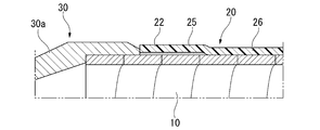
- FIG. 10 is a diagram showing a part of the tip side of the optical cable tow terminal structure of the present embodiment.
- the outer tube 20 has a first portion 25 provided with the adhesive 20a and a second portion 26 not provided with the adhesive 20a.
- the first portion 25 is provided at the front end 22 of the outer tube 20.
- the inner tube 10 and the outer tube 20 are brought into close contact with each other on at least one circumference (the entire circumference in the circumferential direction) of the outer tube 20 in the longitudinal direction.
- the outer tube 20 has a first portion (not shown) provided with an adhesive and a second portion (not shown) provided with no adhesive. ) And.
- the inner tube 10 and the outer tube 20 are in close contact with each other by the first portion. This makes it possible to prevent water from entering the inner tube 10 of the optical cable traction terminal structure.
- FIG. 11 is a diagram of an optical cable housed inside the optical cable traction terminal structure.
- the optical cable 2 is composed of a plurality of optical cables 2.
- the plurality of optical cables 2 are covered with a transparent PVC (polyvinyl chloride) sheet 60.
- the PVC sheet 60 is contracted to match the shapes of a plurality of optical cables, and has, for example, a cut (perforation) 61 in the longitudinal direction thereof.
- the number of cuts 61 is two in parallel along the longitudinal direction. That is, after the optical cable traction terminal has been inserted into the duct tube, the sheet 60 can be easily peeled off by the cut 61 when actually connecting to another optical fiber.
- the number of cuts 61 is two in parallel along the longitudinal direction, but it may be one or three or more.
- the material of the inner tube 10 is stainless steel, but the material is not limited to this.
- the material of the inner tube 10 may be made of plastic instead of metal.
- the holder 4 is fixed to the inner tube 10 by the bolt 7 via the connecting member 40, the holder 4 may be directly fixed to the inner tube 10.
- the inner tube 10 is configured such that the stainless steel plates are fitted by about 1/3 in the width direction and connected in a spiral shape, but the inner tube 10 does not have to be fitted. In this case, the inner diameter of the inner tube 10 can be changed.
Landscapes
- Physics & Mathematics (AREA)
- General Physics & Mathematics (AREA)
- Optics & Photonics (AREA)
- Light Guides In General And Applications Therefor (AREA)
Priority Applications (3)
| Application Number | Priority Date | Filing Date | Title |
|---|---|---|---|
| CN202180027301.1A CN115398300B (zh) | 2020-05-07 | 2021-04-13 | 线缆牵引终端构造 |
| JP2022519918A JP7324943B2 (ja) | 2020-05-07 | 2021-04-13 | ケーブル牽引端末構造 |
| US17/921,836 US11860431B2 (en) | 2020-05-07 | 2021-04-13 | Cable traction terminal structure |
Applications Claiming Priority (2)
| Application Number | Priority Date | Filing Date | Title |
|---|---|---|---|
| US202063021100P | 2020-05-07 | 2020-05-07 | |
| US63/021,100 | 2020-05-07 |
Publications (1)
| Publication Number | Publication Date |
|---|---|
| WO2021225062A1 true WO2021225062A1 (ja) | 2021-11-11 |
Family
ID=78467961
Family Applications (1)
| Application Number | Title | Priority Date | Filing Date |
|---|---|---|---|
| PCT/JP2021/015297 Ceased WO2021225062A1 (ja) | 2020-05-07 | 2021-04-13 | ケーブル牽引端末構造 |
Country Status (4)
| Country | Link |
|---|---|
| US (1) | US11860431B2 (https=) |
| JP (1) | JP7324943B2 (https=) |
| CN (1) | CN115398300B (https=) |
| WO (1) | WO2021225062A1 (https=) |
Families Citing this family (1)
| Publication number | Priority date | Publication date | Assignee | Title |
|---|---|---|---|---|
| JP7325611B2 (ja) * | 2020-03-27 | 2023-08-14 | 株式会社フジクラ | 牽引端末構造体、牽引端付き光ケーブル及び牽引端付き光ケーブルの製造方法 |
Citations (6)
| Publication number | Priority date | Publication date | Assignee | Title |
|---|---|---|---|---|
| JPH0485302U (https=) * | 1990-11-29 | 1992-07-24 | ||
| JP2002131600A (ja) * | 2000-10-25 | 2002-05-09 | Furukawa Electric Co Ltd:The | 光ファイバケーブルの牽引端末構造 |
| JP2006009811A (ja) * | 2004-06-22 | 2006-01-12 | Mitsubishi Cable Ind Ltd | 可撓管及びそれを用いた光ファイババンドル |
| KR100659017B1 (ko) * | 2006-09-29 | 2006-12-21 | 주식회사 티아이엔지니어링건축사사무소 | 건축용 방수 전선관 |
| JP2010217316A (ja) * | 2009-03-13 | 2010-09-30 | Fujikura Ltd | ケーブル牽引端末構造及び光ケーブル |
| JP2016144293A (ja) * | 2015-01-30 | 2016-08-08 | 株式会社ビスキャス | 電力ケーブルの修理用ジョイント |
Family Cites Families (15)
| Publication number | Priority date | Publication date | Assignee | Title |
|---|---|---|---|---|
| US3357423A (en) * | 1965-03-26 | 1967-12-12 | Iota Cam Corp | Surgical light pipe and the like |
| DE3239667A1 (de) * | 1982-10-27 | 1984-05-03 | Philips Kommunikations Industrie AG, 8500 Nürnberg | Mantelelement fuer lichtwellenleiter |
| JPH06214118A (ja) * | 1993-01-18 | 1994-08-05 | Yazaki Corp | 光ファイバケーブル牽引具 |
| JPH09230186A (ja) * | 1996-02-23 | 1997-09-05 | Mitsubishi Cable Ind Ltd | 光ファイバケーブルの端末構造 |
| JP2003232970A (ja) * | 2002-02-08 | 2003-08-22 | Occ Corp | 金属管光ファイバケーブルおよびその製造装置 |
| JP2004133005A (ja) * | 2002-10-08 | 2004-04-30 | Sumitomo Electric Ind Ltd | 光ファイバケーブル及びその製造方法 |
| US6906264B1 (en) * | 2004-06-17 | 2005-06-14 | Southwire Company | Color-coded armored cable |
| US20070083132A1 (en) * | 2005-10-11 | 2007-04-12 | Sharrow James S | Medical device coil |
| KR100952825B1 (ko) * | 2005-12-30 | 2010-04-15 | 주식회사 케이티 | 광케이블 및 광케이블의 인장부재 지지장치 |
| US8331748B2 (en) * | 2009-09-30 | 2012-12-11 | Corning Cable Systems Llc | Armored fiber optic assemblies and methods employing bend-resistant multimode fiber |
| JP5733827B2 (ja) * | 2011-08-11 | 2015-06-10 | タイガースポリマー株式会社 | 通信ケーブル保護管 |
| JP5737245B2 (ja) * | 2011-12-28 | 2015-06-17 | 住友電気工業株式会社 | 光ケーブル端末固定具、光ケーブルの端末固定構造及び光モジュール |
| EP2848187B1 (en) * | 2012-05-11 | 2018-04-04 | Olympus Corporation | Flexible tube for endoscope, and endoscope |
| US9415551B2 (en) * | 2013-06-13 | 2016-08-16 | Corning Cable Systems Llc | Coupling system for a fiber optic cable |
| US11666251B2 (en) * | 2016-10-31 | 2023-06-06 | Heraeus Deutschland GmbH & Co. KG | Signal and torque transmitting torque coil |
-
2021
- 2021-04-13 JP JP2022519918A patent/JP7324943B2/ja active Active
- 2021-04-13 WO PCT/JP2021/015297 patent/WO2021225062A1/ja not_active Ceased
- 2021-04-13 US US17/921,836 patent/US11860431B2/en active Active
- 2021-04-13 CN CN202180027301.1A patent/CN115398300B/zh active Active
Patent Citations (6)
| Publication number | Priority date | Publication date | Assignee | Title |
|---|---|---|---|---|
| JPH0485302U (https=) * | 1990-11-29 | 1992-07-24 | ||
| JP2002131600A (ja) * | 2000-10-25 | 2002-05-09 | Furukawa Electric Co Ltd:The | 光ファイバケーブルの牽引端末構造 |
| JP2006009811A (ja) * | 2004-06-22 | 2006-01-12 | Mitsubishi Cable Ind Ltd | 可撓管及びそれを用いた光ファイババンドル |
| KR100659017B1 (ko) * | 2006-09-29 | 2006-12-21 | 주식회사 티아이엔지니어링건축사사무소 | 건축용 방수 전선관 |
| JP2010217316A (ja) * | 2009-03-13 | 2010-09-30 | Fujikura Ltd | ケーブル牽引端末構造及び光ケーブル |
| JP2016144293A (ja) * | 2015-01-30 | 2016-08-08 | 株式会社ビスキャス | 電力ケーブルの修理用ジョイント |
Also Published As
| Publication number | Publication date |
|---|---|
| JP7324943B2 (ja) | 2023-08-10 |
| CN115398300B (zh) | 2025-07-08 |
| US20230161126A1 (en) | 2023-05-25 |
| CN115398300A (zh) | 2022-11-25 |
| JPWO2021225062A1 (https=) | 2021-11-11 |
| US11860431B2 (en) | 2024-01-02 |
Similar Documents
| Publication | Publication Date | Title |
|---|---|---|
| EP3410167B1 (en) | Optical fiber cable | |
| KR102026037B1 (ko) | 광 케이블 | |
| US6459837B1 (en) | Optical fiber cable with single strength member unit in cable outer jacket | |
| CN112867952B (zh) | 光纤缆线 | |
| US12510716B2 (en) | Optical fiber cable and cable with connector | |
| JP6851960B2 (ja) | 光ファイバケーブル | |
| CN115516356B (zh) | 光缆 | |
| CN114641717A (zh) | 光缆以及光缆的制造方法 | |
| JP4900938B2 (ja) | ドロップケーブル | |
| JP6542648B2 (ja) | 光ファイバケーブル | |
| WO2021225062A1 (ja) | ケーブル牽引端末構造 | |
| WO2022045139A1 (ja) | 光ケーブル部材、牽引部材、及び、牽引方法 | |
| CN114868061B (zh) | 牵引终端结构体、带牵引端的光缆以及带牵引端的光缆的制造方法 | |
| JP7636394B2 (ja) | 収容構造体、牽引端付き光ケーブル及び収容構造体の製造方法 | |
| JPH10148739A (ja) | 架空集合屋外用光ケーブル | |
| JP2004212960A (ja) | 光ファイバケーブル | |
| JP6018156B2 (ja) | 光ケーブル用保護具の装着方法 | |
| JP2016040563A (ja) | 光ファイバケーブル及びワイヤーハーネス | |
| JP2661960B2 (ja) | 多心光コード分岐部 | |
| JP2010128169A (ja) | 光ファイバケーブル | |
| JPH06208025A (ja) | 光ファイバ保持構造 | |
| WO2024028967A1 (ja) | 光ファイバケーブル | |
| JP2003235142A (ja) | ケーブル敷設用管及びその製造方法 | |
| JPH10319285A (ja) | 光ファイバーケーブル用シース、光ファイバーケーブル用シースの製造方法、光ファイバーケーブル用シースに対する光ファイバー素線の挿通方法 | |
| JPH10186161A (ja) | 光ファイバ接続補強部保護用ブーツ、保護構造及び保護方法 |
Legal Events
| Date | Code | Title | Description |
|---|---|---|---|
| 121 | Ep: the epo has been informed by wipo that ep was designated in this application |
Ref document number: 21800010 Country of ref document: EP Kind code of ref document: A1 |
|
| ENP | Entry into the national phase |
Ref document number: 2022519918 Country of ref document: JP Kind code of ref document: A |
|
| NENP | Non-entry into the national phase |
Ref country code: DE |
|
| 122 | Ep: pct application non-entry in european phase |
Ref document number: 21800010 Country of ref document: EP Kind code of ref document: A1 |
|
| WWG | Wipo information: grant in national office |
Ref document number: 202180027301.1 Country of ref document: CN |