WO2021220699A1 - 中継コネクタ - Google Patents
中継コネクタ Download PDFInfo
- Publication number
- WO2021220699A1 WO2021220699A1 PCT/JP2021/013553 JP2021013553W WO2021220699A1 WO 2021220699 A1 WO2021220699 A1 WO 2021220699A1 JP 2021013553 W JP2021013553 W JP 2021013553W WO 2021220699 A1 WO2021220699 A1 WO 2021220699A1
- Authority
- WO
- WIPO (PCT)
- Prior art keywords
- terminal
- relay
- sandwiching
- relay connector
- side terminal
- Prior art date
- Legal status (The legal status is an assumption and is not a legal conclusion. Google has not performed a legal analysis and makes no representation as to the accuracy of the status listed.)
- Ceased
Links
Images


Classifications
-
- H—ELECTRICITY
- H01—ELECTRIC ELEMENTS
- H01R—ELECTRICALLY-CONDUCTIVE CONNECTIONS; STRUCTURAL ASSOCIATIONS OF A PLURALITY OF MUTUALLY-INSULATED ELECTRICAL CONNECTING ELEMENTS; COUPLING DEVICES; CURRENT COLLECTORS
- H01R9/00—Structural associations of a plurality of mutually-insulated electrical connecting elements, e.g. terminal strips or terminal blocks; Terminals or binding posts mounted upon a base or in a case; Bases therefor
- H01R9/22—Bases, e.g. strip, block, panel
- H01R9/24—Terminal blocks
-
- H—ELECTRICITY
- H01—ELECTRIC ELEMENTS
- H01R—ELECTRICALLY-CONDUCTIVE CONNECTIONS; STRUCTURAL ASSOCIATIONS OF A PLURALITY OF MUTUALLY-INSULATED ELECTRICAL CONNECTING ELEMENTS; COUPLING DEVICES; CURRENT COLLECTORS
- H01R4/00—Electrically-conductive connections between two or more conductive members in direct contact, i.e. touching one another; Means for effecting or maintaining such contact; Electrically-conductive connections having two or more spaced connecting locations for conductors and using contact members penetrating insulation
- H01R4/28—Clamped connections, spring connections
- H01R4/38—Clamped connections, spring connections utilising a clamping member acted on by screw or nut
- H01R4/44—Clamping areas on both sides of screw
-
- H—ELECTRICITY
- H01—ELECTRIC ELEMENTS
- H01G—CAPACITORS; CAPACITORS, RECTIFIERS, DETECTORS, SWITCHING DEVICES, LIGHT-SENSITIVE OR TEMPERATURE-SENSITIVE DEVICES OF THE ELECTROLYTIC TYPE
- H01G11/00—Hybrid capacitors, i.e. capacitors having different positive and negative electrodes; Electric double-layer [EDL] capacitors; Processes for the manufacture thereof or of parts thereof
- H01G11/08—Structural combinations, e.g. assembly or connection, of hybrid or EDL capacitors with other electric components, at least one hybrid or EDL capacitor being the main component
-
- H—ELECTRICITY
- H01—ELECTRIC ELEMENTS
- H01G—CAPACITORS; CAPACITORS, RECTIFIERS, DETECTORS, SWITCHING DEVICES, LIGHT-SENSITIVE OR TEMPERATURE-SENSITIVE DEVICES OF THE ELECTROLYTIC TYPE
- H01G4/00—Fixed capacitors; Processes of their manufacture
- H01G4/002—Details
- H01G4/228—Terminals
-
- H—ELECTRICITY
- H01—ELECTRIC ELEMENTS
- H01G—CAPACITORS; CAPACITORS, RECTIFIERS, DETECTORS, SWITCHING DEVICES, LIGHT-SENSITIVE OR TEMPERATURE-SENSITIVE DEVICES OF THE ELECTROLYTIC TYPE
- H01G4/00—Fixed capacitors; Processes of their manufacture
- H01G4/40—Structural combinations of fixed capacitors with other electric elements, the structure mainly consisting of a capacitor, e.g. RC combinations
-
- H—ELECTRICITY
- H01—ELECTRIC ELEMENTS
- H01M—PROCESSES OR MEANS, e.g. BATTERIES, FOR THE DIRECT CONVERSION OF CHEMICAL ENERGY INTO ELECTRICAL ENERGY
- H01M50/00—Constructional details or processes of manufacture of the non-active parts of electrochemical cells other than fuel cells, e.g. hybrid cells
- H01M50/20—Mountings; Secondary casings or frames; Racks, modules or packs; Suspension devices; Shock absorbers; Transport or carrying devices; Holders
-
- H—ELECTRICITY
- H01—ELECTRIC ELEMENTS
- H01M—PROCESSES OR MEANS, e.g. BATTERIES, FOR THE DIRECT CONVERSION OF CHEMICAL ENERGY INTO ELECTRICAL ENERGY
- H01M50/00—Constructional details or processes of manufacture of the non-active parts of electrochemical cells other than fuel cells, e.g. hybrid cells
- H01M50/50—Current conducting connections for cells or batteries
-
- H—ELECTRICITY
- H01—ELECTRIC ELEMENTS
- H01R—ELECTRICALLY-CONDUCTIVE CONNECTIONS; STRUCTURAL ASSOCIATIONS OF A PLURALITY OF MUTUALLY-INSULATED ELECTRICAL CONNECTING ELEMENTS; COUPLING DEVICES; CURRENT COLLECTORS
- H01R11/00—Individual connecting elements providing two or more spaced connecting locations for conductive members which are, or may be, thereby interconnected, e.g. end pieces for wires or cables supported by the wire or cable and having means for facilitating electrical connection to some other wire, terminal, or conductive member, blocks of binding posts
- H01R11/03—Individual connecting elements providing two or more spaced connecting locations for conductive members which are, or may be, thereby interconnected, e.g. end pieces for wires or cables supported by the wire or cable and having means for facilitating electrical connection to some other wire, terminal, or conductive member, blocks of binding posts characterised by the relationship between the connecting locations
- H01R11/09—Individual connecting elements providing two or more spaced connecting locations for conductive members which are, or may be, thereby interconnected, e.g. end pieces for wires or cables supported by the wire or cable and having means for facilitating electrical connection to some other wire, terminal, or conductive member, blocks of binding posts characterised by the relationship between the connecting locations the connecting locations being identical
-
- H—ELECTRICITY
- H01—ELECTRIC ELEMENTS
- H01R—ELECTRICALLY-CONDUCTIVE CONNECTIONS; STRUCTURAL ASSOCIATIONS OF A PLURALITY OF MUTUALLY-INSULATED ELECTRICAL CONNECTING ELEMENTS; COUPLING DEVICES; CURRENT COLLECTORS
- H01R4/00—Electrically-conductive connections between two or more conductive members in direct contact, i.e. touching one another; Means for effecting or maintaining such contact; Electrically-conductive connections having two or more spaced connecting locations for conductors and using contact members penetrating insulation
- H01R4/28—Clamped connections, spring connections
- H01R4/30—Clamped connections, spring connections utilising a screw or nut clamping member
- H01R4/308—Conductive members located parallel to axis of screw
-
- H—ELECTRICITY
- H01—ELECTRIC ELEMENTS
- H01R—ELECTRICALLY-CONDUCTIVE CONNECTIONS; STRUCTURAL ASSOCIATIONS OF A PLURALITY OF MUTUALLY-INSULATED ELECTRICAL CONNECTING ELEMENTS; COUPLING DEVICES; CURRENT COLLECTORS
- H01R9/00—Structural associations of a plurality of mutually-insulated electrical connecting elements, e.g. terminal strips or terminal blocks; Terminals or binding posts mounted upon a base or in a case; Bases therefor
- H01R9/22—Bases, e.g. strip, block, panel
- H01R9/223—Insulating enclosures for terminals
-
- H—ELECTRICITY
- H01—ELECTRIC ELEMENTS
- H01R—ELECTRICALLY-CONDUCTIVE CONNECTIONS; STRUCTURAL ASSOCIATIONS OF A PLURALITY OF MUTUALLY-INSULATED ELECTRICAL CONNECTING ELEMENTS; COUPLING DEVICES; CURRENT COLLECTORS
- H01R2201/00—Connectors or connections adapted for particular applications
- H01R2201/26—Connectors or connections adapted for particular applications for vehicles
-
- H—ELECTRICITY
- H01—ELECTRIC ELEMENTS
- H01R—ELECTRICALLY-CONDUCTIVE CONNECTIONS; STRUCTURAL ASSOCIATIONS OF A PLURALITY OF MUTUALLY-INSULATED ELECTRICAL CONNECTING ELEMENTS; COUPLING DEVICES; CURRENT COLLECTORS
- H01R4/00—Electrically-conductive connections between two or more conductive members in direct contact, i.e. touching one another; Means for effecting or maintaining such contact; Electrically-conductive connections having two or more spaced connecting locations for conductors and using contact members penetrating insulation
- H01R4/28—Clamped connections, spring connections
- H01R4/30—Clamped connections, spring connections utilising a screw or nut clamping member
- H01R4/305—Clamped connections, spring connections utilising a screw or nut clamping member having means for facilitating engagement of conductive member or for holding it in position
-
- Y—GENERAL TAGGING OF NEW TECHNOLOGICAL DEVELOPMENTS; GENERAL TAGGING OF CROSS-SECTIONAL TECHNOLOGIES SPANNING OVER SEVERAL SECTIONS OF THE IPC; TECHNICAL SUBJECTS COVERED BY FORMER USPC CROSS-REFERENCE ART COLLECTIONS [XRACs] AND DIGESTS
- Y02—TECHNOLOGIES OR APPLICATIONS FOR MITIGATION OR ADAPTATION AGAINST CLIMATE CHANGE
- Y02E—REDUCTION OF GREENHOUSE GAS [GHG] EMISSIONS, RELATED TO ENERGY GENERATION, TRANSMISSION OR DISTRIBUTION
- Y02E60/00—Enabling technologies; Technologies with a potential or indirect contribution to GHG emissions mitigation
- Y02E60/10—Energy storage using batteries
Definitions
- This disclosure relates to a relay connector.
- Patent Document 1 Conventionally, as a connection structure for electrically connecting two devices in a vehicle or the like, the one of Patent Document 1 is known.
- the second bus bar terminal connected to the electric wire extending from the other device side is inserted into the housing with respect to the first bus bar terminal installed in the housing of the bus bar block provided on one device side. It is inserted through the mouth and overlapped.
- the first bus bar terminal and the second bus bar terminal are electrically connected to each other in the housing by bolting to a nut previously overlapped on the opposite surface of the first bus bar.
- This disclosure has been completed based on the above circumstances, and provides a relay connector capable of easily performing electrical connection work between two devices.
- the relay connector of the present disclosure includes a first device side terminal and a second device side terminal that are electrically connected, a first connection portion that is connected to the first device side terminal, and the second device side terminal.
- a conductive relay terminal having a second connecting portion to be connected, a first sandwiching portion arranged to face the relay terminal and sandwiching the first device side terminal between the first connecting portion, and a first sandwiching portion.
- a sandwiching member having a second sandwiching portion for sandwiching the second device-side terminal with the second connecting portion, and a connector case are provided, and the connector case inserts the first device-side terminal.
- a first insertion port for the purpose and a second insertion port for inserting the second device side terminal are provided, and the holding member is provided with the first device side terminal inserted from the first insertion port. And a guide portion for guiding the second device side terminal inserted from the second insertion port between the first sandwiching portion and the second sandwiching portion and the relay terminal is formed, respectively. ..
- the electrical connection work between the two devices can be easily performed.
- FIG. 1 is a schematic view showing a vehicle equipped with the relay connector of the first embodiment.
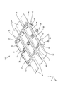
- FIG. 2 is an exploded perspective view showing a relay connector.
- FIG. 3 is a perspective view showing a relay connector in a connected state.
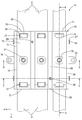
- FIG. 4 is a plan view showing a relay connector in a connected state.
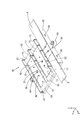
- FIG. 5 is a perspective view showing a virtual partially assembled state for explaining the configuration of the relay connector.
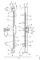
- FIG. 6 is a plan view showing a virtual partially assembled state for explaining the configuration of the relay connector.
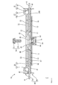
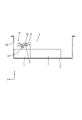
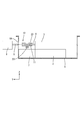
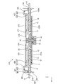
- FIG. 7 is an exploded cross-sectional view showing a relay connector corresponding to the AA cross section of FIG.
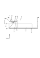
- FIG. 8 is a cross-sectional view showing an assembly process of the relay connector corresponding to the AA cross section of FIG.
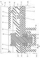
- FIG. 9 is a cross-sectional view showing an assembly process of the relay connector corresponding to the AA cross section of FIG. 4 (a state in which the lower case and the upper case are assembled).
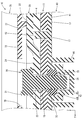
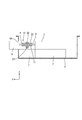
- FIG. 10 is a cross-sectional view showing an assembly process of the relay connector corresponding to the AA cross section of FIG. 4 (state before fastening with the external terminal inserted).
- FIG. 11 is a cross-sectional view showing a relay connector in a connected state corresponding to the AA cross section of FIG. 4 (a state in which the fastening member is fastened).
- FIG. 12 is a partially enlarged cross-sectional view of the vicinity of the locking structure of the locking piece in FIG.
- FIG. 13 is a partially enlarged cross-sectional view of the vicinity of the locking structure of the locking piece in FIG. 10 (state after the external terminal is inserted).
- FIG. 14 is a partially enlarged cross-sectional view of the vicinity of the fastening portion in FIG.
- FIG. 15 is a view showing a fastening process of the fastening member, and is a partially enlarged cross-sectional view showing a state in which the shaft portion of the bolt is screwed into the nut-side fastening hole of the nut after the external terminal is inserted.
- FIG. 16 is a view in which the bolt is further tightened from the state of FIG.
- FIG. 13 is a partially enlarged cross-sectional view showing a state in which the nut is in contact with the lower surface of the first terminal.
- FIG. 17 is a view in which bolts are further tightened from the state of FIG. 14, and is a partially enlarged cross-sectional view showing a state in which the upper surface of the nut is lifted from the upper surface of the bottom and the first terminal is pulled up to the second terminal side.
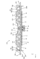
- FIG. 18 is a cross-sectional view showing an assembly process of the relay connector corresponding to the BB cross section of FIG. 4 (a state in which the first terminal is attached to the lower case and the second terminal is attached to the upper case).
- FIG. 19 is a cross-sectional view showing an assembly process of the relay connector corresponding to the BB cross section of FIG.
- FIG. 20 is a cross-sectional view showing a relay connector in a connected state corresponding to the BB cross section of FIG. 4 (a state in which the fastening member is fastened).
- FIG. 21 is a cross-sectional view showing an assembly process of the relay connector corresponding to the CC cross section of FIG. 4 (a state in which the first terminal is attached to the lower case and the second terminal is attached to the upper case).
- FIG. 22 is a cross-sectional view showing a relay connector in a connected state corresponding to the CC cross section of FIG.
- FIG. 23 is a schematic view showing a process of installing the relay connector in the metal housing.
- FIG. 24 is a schematic view showing a process of storing the storage pack in the metal housing.
- FIG. 25 is a schematic view showing a process of inserting the storage pack side terminal into the relay connector.
- FIG. 26 is a schematic view showing a process of bringing the PCU closer to the metal housing.
- FIG. 27 is a schematic view showing a process of inserting the PCU side terminal into the relay connector.
- FIG. 28 is a schematic view showing a process of connecting the storage pack side terminal and the PCU side terminal by fastening bolts.
- FIG. 29 is a schematic view of a state in which the metal housing is closed with a metal cover.
- FIG. 30 is a plan view showing the relay connector in the connected state of the second embodiment.
- FIG. 31 is a cross-sectional view showing a relay connector in a connected state.
- FIG. 32 is a perspective view showing the holding plate of the third embodiment.
- FIG. 33 is a cross-sectional view showing a relay connector in a connected state.
- FIG. 34 is a plan view showing the second terminal of another embodiment.
- FIG. 35 is a cross-sectional view showing a relay connector in a connected state.
- FIG. 36 is a plan view showing the second terminal of another embodiment.
- FIG. 37 is a cross-sectional view showing a relay connector in a connected state.
- the relay connector of the present disclosure includes a first device-side terminal and a second device-side terminal that are electrically connected, a first connection portion that is connected to the first device-side terminal, and the second device.
- a holding member having a second holding portion for holding the second device side terminal between the portion and the second connecting portion, and a connector case are provided, and the connector case includes the first device side terminal.
- the first insertion port for inserting and the second insertion port for inserting the terminal on the second device side are provided, and the first device inserted from the first insertion port is provided in the holding member.
- a guide portion for guiding the side terminal and the second device side terminal inserted from the second insertion port between the first sandwiching portion and the second sandwiching portion and the relay terminal is formed, respectively. ing.
- the first device side terminal and the second device side terminal are inserted between the relay terminal and the holding member in order to establish an electrical connection
- the first device side terminal and the second device side are used.
- Each tip portion in the insertion direction of the terminal is guided to a regular position by a guide portion provided on the holding member. Therefore, it is not necessary for the operator to manually align each terminal while visually observing each terminal. For example, even when the work space is narrow or the operability of the electric wire connected to the terminal is not good, the connection work can be easily performed.
- the guide portion is an inclined surface that inclines from the first holding portion and the second holding portion toward the first insertion port side and the second insertion opening side, and the inclined direction of the inclined surface is It is preferable that each direction is away from the relay terminal.
- a guide portion can be provided on the sandwiching member with a simple configuration.
- the connector case is preferably configured by assembling a lower case that holds one of the relay terminal and the holding member and an upper case that holds the other of the relay terminal and the holding member.
- the relay terminal and the holding member can be easily attached to the connector case.
- the holding member is held in the upper case, and the locking portion provided on the holding member is opposed to the locked portion provided on the upper case, the first holding portion and the first holding portion. 2 It is preferable that the sandwiching portion is locked so as to be displaceable in the direction toward and away from the relay terminal.
- the dimension of the gap between the holding member and the relay terminal is smaller than the thickness dimension of the terminals on the first device side and the terminals on the second device side when they are not inserted.
- An urging member may be provided on the surface of the holding member opposite to the relay terminal to urge the holding member toward the relay terminal side.
- the first device side terminal and the second device side terminal inserted into the relay connector are pressed against the relay terminal by the holding member, so that the electrical connection state can be improved. can.
- the cross section of the sandwiching member along the arrangement direction of the first sandwiching portion and the second sandwiching portion may form a waveform.
- the first device side terminal and the second device side terminal inserted into the relay connector are pressed against the relay terminal by the elastic force of the corrugated holding member, so that the electrical connection state is better. Can be.
- the sandwiching member may be formed of a conductive member.
- the first device side terminal and the second device side terminal inserted in the relay connector are electrically connected by both the sandwiching member and the relay terminal, so that the electrical connection state can be adjusted. It can be better.
- the holding member may be made of stainless steel.
- the sandwiching member is made of stainless steel, which has high rigidity and is not easily deformed, so that the force for sandwiching the first device side terminal and the second device side terminal between the relay terminal and the sandwiching member can be increased. Can be held firmly.
- the first device-side terminal and the second device-side terminal inserted in the relay connector can be sandwiched between the relay terminal and the sandwiching member with a stronger force, and thus electrically.
- the connection condition will be even better.
- FIG. 1 relates to a first embodiment in which the present disclosure is applied to a relay connector 10 for connecting a power storage pack 2 mounted on a vehicle 1 such as an electric vehicle or a hybrid vehicle and a PCU 8 which is a device outside the power storage pack 2.
- a relay connector 10 for connecting a power storage pack 2 mounted on a vehicle 1 such as an electric vehicle or a hybrid vehicle and a PCU 8 which is a device outside the power storage pack 2.
- the power storage pack 2 (an example of the first device) is used as a power source for driving the vehicle 1, and is arranged near the center of the vehicle 1 as shown in FIG.
- a PCU (Power Control Unit) 8 (an example of a second device) is arranged at the front of the vehicle 1.
- the power storage pack 2 and the PCU 8 are connected to each other via the relay connector 10.
- the power storage pack 2 is formed by fixing a plurality of power storage modules composed of a plurality of power storage elements connected in series on a base plate by an insulating protector.
- the power storage element may be a secondary battery such as a nickel hydrogen secondary battery or a lithium ion secondary battery, or may be a capacitor. In this embodiment, the power storage element is a lithium ion battery.
- a relay, a current detector, a fuse, etc. as protective members are connected to the power storage pack 2. As shown in FIG. 24, these protective members are housed in a junction box 3 installed on the upper surface of the front end of the power storage pack 2. From this junction box 3, the tab-shaped storage pack side terminal 4 for connecting to the PCU 8 via the relay connector 10 faces forward in the horizontal direction with the plate surface facing in the vertical direction (Z direction). A plurality of (three in this embodiment) are projected side by side in the (X direction).
- the storage pack 2 and the junction box 3 are housed in the metal housing 5.
- the metal housing 5 has a box shape with an open upper surface, and the opening thereof is closed by a metal cover 6 (see FIG. 29).
- a connector base 7 for mounting the relay connector 10 is provided in front of the inside of the metal housing 5. Further, on the front wall of the metal housing 5, when the relay connector 10 is installed in the normal position of the connector base 7 in the normal posture, the relay connector 10 is located at a position corresponding to the second insertion port 92 of the relay connector 10, which will be described later. A case-side insertion port 5A that communicates with the second insertion port 92 is formed.
- a tab-shaped PCU-side terminal 9 for connecting to the storage pack 2 via the relay connector 10 faces the plate surface in the vertical direction (Z direction).
- a plurality (three in this embodiment) are projected side by side (X direction) in a state of facing toward.
- the width dimension and the thickness dimension of these PCU side terminals 9 are the same as the width dimension and the thickness dimension of the storage pack side terminal 4.
- the relay connector 10 includes a first terminal 11 (an example of a relay terminal), a second terminal 20 (an example of a holding member), a lower case 40 that positions and holds the first terminal 11, and a second. It is configured to include an upper case 70 for positioning and holding the terminal 20, and a fastening member (bolt 30 and nut 33) for fastening the first terminal 11 and the second terminal 20.
- a fastening member bolt 30 and nut 33
- the first terminal 11 is made of a rectangular copper plate, and one end side (rear side) in the longitudinal direction is a first connection portion 12 which is electrically connected to the above-mentioned storage pack side terminal 4, and the other end side (front side) is described above. It is a second connection portion 13 which is electrically connected to the terminal 9 on the side of the PCU.
- a first terminal side fastening hole 15 through which the shaft portion 32 of the bolt 30 for fastening the first terminal 11 to the second terminal 20 is inserted is provided through the plate surface. There is. Further, as shown in FIG.
- a pair of first terminal-side convex portions 16 for positioning the first terminal 11 on the lower case 40 are formed by press molding near both ends in the longitudinal direction so as to project toward the lower surface side. Has been done. Further, between each of the first terminal-side convex portions 16 and the first terminal-side fastening holes 15, a first terminal-side hole portion 17 for inserting the lower case-side convex portion 48 provided on the lower case 40 side is provided as a plate. It is provided through the surface.
- the first terminal side hole portion 17 has an elongated hole shape that is long in the longitudinal direction (see FIG. 6).
- the width dimension (dimension in the X-axis direction) of these first terminals 11 is larger than the width dimension of the storage pack side terminal 4 and the PCU side terminal 9.
- the second terminal 20 is made of a copper plate like the first terminal 11, and extends from a rectangular main body 21 arranged on the upper side of the first terminal 11 and both end edges of the main body 21 in the longitudinal direction. It includes a pair of locking pieces 27.
- One end side (rear) of the main body 21 in the longitudinal direction is a first holding portion 22 for sandwiching the storage pack side terminal 4 with the first connecting portion 12 of the first terminal 11, and the other end side (front).
- Is a second sandwiching portion 23 that sandwiches the PCU side terminal 9 with the second connecting portion 13 of the first terminal 11.
- the width dimension of the main body 21 is the same as the width dimension of the first terminal 11.
- the central portion of the main body 21 in the longitudinal direction is a recess 24 recessed downward (on the side of the first terminal 11) over the entire width direction (X direction), and the second terminal 20 is located in the center thereof.
- the second terminal side fastening hole 25 through which the shaft portion 32 of the bolt 30 for fastening the first terminal 11 is inserted is provided so as to penetrate the plate surface.
- the length dimension (dimension in the Y-axis direction) of the recess 24 in the longitudinal direction of the main body 21 is shorter than the length dimension between the pair of first terminal side holes 17 of the first terminal 11 described above. ing. That is, the recess 24 has a length dimension that fits between the pair of holes 17 on the first terminal side (see FIG. 9).
- the depth dimension of the recess 24 is equal to or smaller than the thickness dimension of the storage pack side terminal 4 and the PCU side terminal 9.
- a pair of notches 26 for fitting the terminal locking claws 56 of the lower case 40, which will be described later, are formed in the pair of side edge portions (edge portions along the Y direction) of the recess 24 (FIGS. 2 and 2). See FIG. 18).
- the pair of locking pieces 27 are pieces bent in a crank shape upward (Z direction, direction away from the first terminal 11) and outward from both end edges in the longitudinal direction of the main body portion 21. It is formed in a shape.
- the base end side of the pair of locking pieces 27 is a guide portion 28 extending upward in an oblique manner with respect to the main body portion 21, and the lower surface (the surface on the first terminal 11 side) thereof is the above-mentioned storage storage.
- the pack-side terminal 4 and the PCU-side terminal 9 are provided as an inclined guide surface 28A that guides the pack-side terminal 4 and the PCU-side terminal 9 between the first terminal 11 and the main body 21 of the second terminal 20. Further, the tip side extends outward in parallel with the main body portion 21, and is a locking portion 29 for locking to the upper case 70, which will be described later.
- the metal constituting the first terminal 11 and the second terminal 20 is not particularly limited, and in addition to copper, any metal such as copper alloy, aluminum, aluminum alloy, stainless steel (SUS), nickel, nickel alloy, etc. can be used. It can be selected as appropriate.
- the surfaces of the first terminal 11 and the second terminal 20 may be plated with a metal different from the metal constituting the terminal. As the metal plated on the surface of the terminal, any metal such as tin, solder, and nickel can be appropriately selected. Further, the first terminal 11 and the second terminal 20 may be made of the same kind of metal, or may be made of different kinds of metals.
- the lower case 40 is made of synthetic resin (insulating), covers the above-mentioned first terminal 11 from below and from the side (left-right direction, X direction), and has an elongated rectangular shape in the front-rear direction (Y direction) as a whole. It is provided with a plate-shaped bottom wall 41.
- the bottom wall 41 is arranged so that a pair of side edges are along the front-rear direction.
- the length dimension of the bottom wall 41 in the front-rear direction is designed so that the second terminal 20 held in the upper case 70 can be accommodated inside when the upper case 70 described later is assembled to the lower case 40. ing.
- the accommodating recess 43 On the upper surface of the bottom wall 41, three positioning recesses 42 accommodating the first terminal 11 are provided side by side.
- the depth of the positioning recess 42 is designed to be the same as the plate thickness of the first terminal 11.
- a housing recess 43 for housing the nut 33 as a fastening member is formed so as to project toward the lower surface side.
- the accommodating recess 43 has a two-stage structure consisting of a nut accommodating portion 44 that is recessed downward from the upper surface of the positioning recess 42 and a relief portion 45 that is recessed further downward from the nut accommodating portion 44. It is said that.
- the nut accommodating portion 44 has a hexagonal shape in a plan view, and the hexagon nut 33 is fitted inside the nut accommodating portion 44 in a state of being fixed in the rotational direction and movable in the vertical direction (Z direction). ..
- the nut accommodating portion 44 is arranged at a depth at which the upper surface of the nut 33 is at the same position as the upper surface of the positioning recess 42 when the nut 33 is fitted inside, or at a position where the upper surface is lower than the upper surface of the positioning recess 42. It is set to the depth to be set (see FIG. 14).
- the inner diameter of the relief portion 45 is smaller than the inner diameter of the nut accommodating portion 44, and the shaft portion 32 of the bolt 30 screwed into the nut 33 can be released inside the relief portion 45.
- a frame-shaped protective wall 46 is provided on the lower surface of the bottom wall 41 so as to surround the outer circumference of the accommodating recess 43.
- the lower case side hole 47 is provided. Further, in a state where the first terminal 11 is housed, a lower case side convex portion 48 is provided at a position corresponding to the first terminal side hole portion 17.
- the first terminal 11 is housed in the positioning recess 42, the first terminal side convex portion 16 is fitted into the lower case side hole 47, and the lower case side convex 48 is fitted into the first terminal side hole 17. Therefore, the lower case 40 is positioned in a fixed state along the upper surface of the bottom wall 41 in the direction (XY directions) (see FIG. 8).
- first terminal 11 is moved upward from the claw portion 58 of the terminal locking claw 56, which will be described later, by engaging the pair of side edge portions with the pair of terminal locking claws 56 of the lower case 40, which will be described later. Movement is restricted (see Figure 18).
- the lower case side convex portion 48 has a rising dimension from the accommodating recess 43 larger than the thickness dimension of the first terminal 11, and is in a state where the first terminal 11 is accommodated in the accommodating recess 43. It protrudes upward from the upper surface of the 1 terminal 11 (see FIG. 8).
- the adjacent positioning recesses 42 are partitioned by a pair of partition walls 51 that extend in the front-rear direction (Y direction) and rise from both the upper and lower surfaces of the bottom wall 41. There is. By these partition walls 51, the terminals connected to the adjacent first terminal 11 and the first terminal 11 are maintained in an insulated state. Further, as shown in FIGS. 5 and 21, the pair of partition walls 51 are respectively located near the opposite ends in the front-rear direction, and the partition wall 51 and the connecting wall 85 of the upper case 70, which will be described later, are connected to each other. Lower case side positioning holes 52 for positioning are provided one by one.
- the pair of side edges extending in the front-rear direction of the bottom wall 41 are provided with side walls 53 that rise toward both the upper and lower sides of the bottom wall 41.
- the rising dimensions of the partition wall 51 and the side wall 53 from the bottom wall 41 are the same on both the upper surface side and the lower surface side. That is, the upper end surface and the lower end surface of the partition wall 51 and the side wall 53 are set to have the same dimensions.
- the pair of side walls 53 are formed with a pair of mounting portions 54 for fixing the lower case 40 (relay connector 10) to the connector base 7 by projecting from the lower end of the center in the front-rear direction toward the outside (X direction). ing. Further, the pair of side walls 53 are formed with claw-shaped lower case side locking portions 55 for locking the upper case 70 to the lower case 40 located in front of and behind each mounting portion 54. .. The pair of side walls 53 are provided with a total of four lower case side locking portions 55.
- a total of six pair of terminal locking claws 56 are provided in the center of the bottom wall 41 in the front-rear direction (see FIGS. 5 and 6). These terminal locking claws 56 are provided adjacent to the respective positioning recesses 42, and as shown in FIG. 18, each of these terminal locking claws 56 is provided at the tip of the elastically deformed portion 57 erected upward from the bottom wall 41. It has a substantially L-shape in which a claw portion 58 extending toward the positioning recess 42 side is formed. The lower surface of the claw portion 58 is set so as to be located above the upper surface of the first terminal 11 in a state where the first terminal 11 is housed in the positioning recess 42. That is, the first terminal 11 is restricted from moving upward from the claw portion 58 in a state where the first terminal 11 can move up and down below the claw portion 58 by the terminal locking claw 56.
- the front end edge of the bottom wall 41 is provided with a front wall 61 that rises toward both the upper and lower sides of the bottom wall 41.
- the rear end edge of the bottom wall 41 is also provided with a rear wall 62 that rises toward both the upper and lower sides of the bottom wall 41.
- the rising dimensions of the front wall 61 and the rear wall 62 from the bottom wall 41 are the same as the rising dimensions of the partition wall 51 and the side wall 53 from the bottom wall 41 on both the upper surface side and the lower surface side. That is, the front wall 61, the rear wall 62, the partition wall 51, and the side wall 53 are set to have dimensions so that their upper end surfaces and lower end surfaces are at the same position (see FIG. 7).
- the front wall 61 and the rear wall 62 have a concave opening 63 for exposing the upper surface of the bottom wall 41 to the outside when the upper case 70 is assembled to the lower case 40.
- the concave opening 63 has a form in which the front wall 61 and the rear wall 62 are recessed downward from the upper ends, and the center line in the width direction (X direction) thereof is a positioning recess. It is formed at a position corresponding to the center line in the width direction of 42.
- the notch depth from the upper end thereof is the same as the height dimension from the upper end to the bottom wall 41, and the width dimension is larger than the width dimension of the storage pack side terminal 4 and the PCU side terminal 9. It is said that.
- the edge portion (corner portion of the front end and the rear end) of the portion of the concave opening 63 that is continuous with the upper surface of the bottom wall 41 is an inclined surface 64 that is obliquely cut out downward. ..
- the upper case 70 is also made of synthetic resin like the lower case 40, and holds the three above-mentioned second terminals 20 while covering them from above and closes the opening on the upper side of the lower case 40. It has an elongated rectangular shape in the direction). More specifically, the upper case 70 has a form in which three holding portions 71 for holding each of the second terminals 20 are connected by a connecting wall 85.
- the first holding portion 71 includes an elongated rectangular ceiling wall 72 that covers the second terminal 20 from above, and a peripheral wall 73 that extends upward and downward from the peripheral edge of the ceiling wall 72.
- a pair of portions extending in the longitudinal direction (Y direction) will be referred to as a side wall portion 74, and among the portions extending in the width direction (X direction), the front side will be referred to as the front wall portion 75 and the rear side will be referred to as the rear wall portion 76.
- the length dimension (dimension in the Y direction) of the side wall portion 74 of the peripheral wall 73 is longer than the dimension in the longitudinal direction of the second terminal 20, and the length dimension (dimension in the X direction) of the front wall 61 and the rear wall 62 is The dimensions are the same as the dimensions in the width direction of the main body 21 of the second terminal 20.
- four ribs 77 are formed so as to bridge the pair of side wall portions 74 (see FIG. 7).
- the height dimension of these ribs 77 from the ceiling wall 72 is the same as the height dimension of the portion of the pair of side wall portions 74 protruding toward the lower surface side from the ceiling wall 72. That is, the upper surface of the main body 21 of the second terminal 20 can come into contact with both the lower end surfaces of the pair of side wall portions 74 and the lower end surfaces of the four ribs 77 (see FIG. 8).
- a rectangular hole 78 for bolting the first terminal 11 and the second terminal 20 is provided in the center of the ceiling wall 72.
- the inner diameter of the hole 78 is designed to be larger than the outer diameter of the head 31 of the bolt 30.
- a pair of rectangular locking piece insertion holes 79 for inserting the pair of locking pieces 27 of the second terminal 20 described above are formed in the ceiling wall 72 near both ends in the longitudinal direction.
- the width dimension of these locking piece insertion holes 79 is set to be slightly larger than the width dimension of the locking piece 27 of the second terminal 20.
- the portions adjacent to the front end and the rear end of the ceiling wall 72 are the locking pieces of the second terminal 20 inserted into the locking piece insertion holes 79.
- An elastic locking piece 81 for locking the 27 is provided.
- the elastic locking piece 81 is locked at the elastically deformed portion 82 that rises inward from the lower ends of the front wall portion 75 and the rear wall portion 76 in a U shape, and at the upper end of the elastically deformed portion 82. It is composed of a claw portion 83 that protrudes toward the one-side insertion hole 79 side.
- the claw portion 83 has an inclined surface shape in which the lower surface side is on the locking piece insertion hole 79 side and is inclined upward, and the upper surface is a flat surface parallel to the ceiling wall 72.
- the upper surface of the claw portion 83 is located above the upper surface of the ceiling wall 72.
- the elastic locking piece 81 extends in the vertical direction from the portion of the hole edge portion of the locking piece insertion hole 79 adjacent to the front end and the rear end of the ceiling wall 72. Further, the elastic locking piece 81 is formed by cutting out a part of a wall-shaped locking piece positioning portion 84 that surrounds the locking piece insertion hole 79 in a C shape. The upper end surface of the locking piece positioning portion 84 is flush with the upper end surface of the peripheral wall 73. The upper surface of the claw portion 83 of the elastic locking piece 81 described above has the peripheral wall 73 and the locking piece positioning on the upper surface of the locking piece 27 in a state where the locking piece 27 is locked to the upper surface of the claw portion 83. The height is set to be located below the upper end surface of the portion 84.
- the upper case 70 As shown in FIGS. 4, 18, and 21, three of the above-mentioned holding portions 71 are arranged in the horizontal direction (X direction), and the side wall portions 74 of the adjacent holding portions 71 are arranged in the front-rear direction. It is in the form of being connected by an extending plate-shaped connecting wall 85. Further, the pair of side wall portions 74 located at both ends in the width direction (X direction) are provided with auxiliary walls 86 extending in the front-rear direction and projecting outward at the same height position as the connecting wall 85. .. These auxiliary walls 86 come into contact with the upper end surface of the side wall 53 of the lower case 40 to support the upper case 70 when the upper case 70 is assembled to the lower case 40 (see FIGS.
- auxiliary wall 86 is provided with a total of four upper case side locking pieces 87 for locking to the lower case side locking portion 55 of the lower case 40 described above (see FIG. 2). These upper case side locking pieces extend downward in a U shape at a position corresponding to the lower case side locking portion 55 on the auxiliary wall.
- the pair of connecting walls 85 are located closer to the opposite ends in the front-rear direction, and the upper case for positioning the connecting wall 85 and the partition wall 51 of the lower case 40.
- One side positioning hole 88 is provided. These upper case side positioning holes 88 are provided at positions corresponding to the above-mentioned lower case side positioning holes 52 in a state where the upper case 70 is assembled to the lower case 40, and are bolted to each other.
- the upper case side positioning hole 88 located on the front side has a long hole shape that is long in the front-rear direction.
- the elastically deformed portion 57 elastically returns, and the lower surface of the claw portion 58 faces the upper surface of the first terminal 11.
- the lower case side convex portion 48 of the lower case 40 is inserted into the first terminal side hole portion 17 of the first terminal 11, and the first terminal side convex portion of the first terminal 11 is inserted into the lower case side hole portion 47 of the lower case 40. 16 is fitted.
- the first terminal side hole portion 17 has a long hole shape long in the front-rear direction, the tolerance can be absorbed when the lower case side convex portion 48 is inserted.
- the first terminal 11 is immovable in the direction along the bottom wall 41 (XY directions) and is slightly movable in the vertical direction (Z direction). Positioned against. In this state, the first terminal side fastening hole 15 of the first terminal 11 is arranged so as to overlap the nut side fastening hole 34 of the nut 33 in the vertical direction (Z direction).
- the pair of locking pieces 27 of the second terminal 20 are positioned so as to overlap the pair of locking piece insertion holes 79 from the back surface (lower surface in FIG. 7) side of the upper case 70. Then, the second terminal 20 is pushed into the upper case 70 side. Then, the tip of each locking piece 27 (locking portion 29) comes into contact with the claw portion 83 of the elastic locking piece 81 of the upper case 70, and presses the inclined lower surface of the claw portion 83, thereby causing the elastically deformed portion. 82 is gradually elastically deformed toward the outside.
- the elastically deformed portion 82 elastically returns, and the locking portion 29 of the locking piece 27 is locked to the upper surface of the claw portion 83.
- the pressing force is not required, so that the operator can lock the second terminal 20 with respect to the upper case 70. Can be confirmed. As a result, the second terminal 20 is held by the upper case 70.
- the second terminal 20 is held in the upper case 70 in a state of being movable in the direction of approaching and moving away from the upper case 70 (vertical direction, Z direction) (see FIG. 12). .. That is, in a state where the lower surface of the locking piece 27 of the second terminal 20 is in contact with the upper surface of the claw portion 83, between the lower surface of the rib 77 provided on the lower surface of the lower case 40 and the upper surface of the second terminal 20. , It is set so that a gap is formed.
- the upper case 70 is attached to the lower case 40 (see FIGS. 9 and 19). Specifically, the upper case 70 is brought closer to the lower case 40 so that the second terminal 20 faces the first terminal 11, and the two pairs of upper case side locking pieces 87 are placed on the two pairs of lower case side locking portions 55. Make a contact. Then, when the upper case 70 is pushed downward, the upper case side locking piece 87 elastically deforms outward along the upper surface of the lower case side locking portion 55 and gets over the lower case side locking portion 55. At that point, it elastically returns and locks with the lower case side locking portion 55. As a result, the connector case 90 to which the upper case 70 and the lower case 40 are assembled is configured (see FIG. 3).
- the relay connector 10 is assembled (however, in this state, the bolt 30 is not fastened).
- a second wall 61 surrounded by a concave opening of the lower case 40 and a front wall portion 75 of the upper case 70.
- the insertion port 92 is formed on the front surface of the connector case 90.
- a first insertion port 91 surrounded by a rear wall 62 having a concave opening of the lower case 40 and a rear wall portion 76 of the upper case 70 is formed.
- a gap narrower than the thickness dimension of the storage pack side terminal 4 and the PCU side terminal 9 is formed between the first terminal and the second terminal 20 arranged to face each other.
- the second terminal side fastening hole 25 of the second terminal 20 the first terminal side fastening hole 15 of the first terminal 11, and the nut side fastening of the nut 33 are fastened.
- the holes 34 are arranged so as to overlap each other.
- the relay connector 10 described above is used as follows in the connection process of the storage pack side terminal 4 and the PCU side terminal 9.
- the relay connector 10 is fixed at a predetermined position of the connector base 7 installed in the metal housing 5. Specifically, the relay connector 10 is fixed to the connector base 7 by bolting the pair of mounting portions 54 provided on the connector case 90 (lower case 40) to the connector base 7. In this state, the relay connector 10 is arranged such that the second insertion port 92 is superimposed on the case-side insertion port 5A of the metal housing 5.
- the storage packs 2 having the junction box 3 installed above are housed in the metal housing 5 and moved forward, and three of them project forward from the junction box 3.
- the tab-shaped storage pack side terminal 4 is inserted into the inside from the first insertion port 91 of the relay connector 10 (see FIG. 25).
- the tip of the power storage pack side terminal 4 inserted inside the relay connector 10 is guided along the lower surface (guide surface 28A) of the guide portion 28 of the second terminal 20, and the first connection portion of the first terminal 11 is guided. It is easily inserted between the 12 and the first sandwiching portion 22 of the second terminal 20.
- the second terminal 20 is held so as to be movable in the vertical direction with respect to the upper case 70 as described above, the gap between the first connecting portion 12 and the first holding portion 22 is on the storage pack side. Even if the thickness of the terminal 4 is slightly narrower, the storage pack side terminal 4 can easily enter between the first connecting portion 12 and the first holding portion 22 while pushing up the second terminal 20. Further, the first holding portion 22 of the second terminal 20 is pushed up, but is in a state of being exactly overlapped with the storage pack side terminal 4 by its own weight (see FIGS. 10, 13, and 19).
- the tip of the inserted power storage pack side terminal 4 abuts on the lower case side convex portion 48 in the front-rear direction (Y direction). Positioning is done.
- the PCU 8 is brought closer to the metal housing 5 from the front side of the metal housing 5 so that the tip of the PCU side terminal 9 faces the metal housing 5.
- the second insertion port 92 of the relay connector 10 is exposed to the case-side insertion port 5A provided on the front surface of the metal housing 5, so that the PCU-side terminal 9 is in this case. It is inserted into the connector case 90 from the second insertion port 92 of the relay connector 10 through the side insertion port 5A.
- the tip end portion of the PCU side terminal 9 is guided along the lower surface (guide surface 28A) of the guide portion 28 of the second terminal 20, and the second connection of the first terminal 11 is made. It is inserted between the portion 13 and the second sandwiching portion 23 of the second terminal 20.
- the second terminal 20 is held so as to be movable in the vertical direction with respect to the upper case 70. Therefore, even if the gap between the second connecting portion 13 and the second sandwiching portion 23 is narrower than the thickness dimension of the PCU side terminal 9, the PCU side terminal 9 pushes up the second terminal 20 and the second connecting portion. It can be easily entered between the 13 and the second holding portion 23. Further, while the second holding portion 23 of the second terminal 20 is pushed up, it overlaps with the PCU side terminal 9 due to its own weight.
- the tip of the inserted PCU side terminal 9 abuts on the lower case side convex portion 48, and positioning in the front-rear direction (Y direction) can be performed. It is done (see FIG. 10).
- the second terminal 20 is slightly pushed up by the storage pack side terminal 4 and the PCU side terminal 9, and the first holding portion 22 and the second holding portion 23 of the second terminal 20 are held.
- the upper surface of the upper case 70 is in contact with the rib 77 on the lower surface of the upper case 70, and the lower surface of the locking portion 29 of the second terminal 20 is separated from the upper surface of the claw portion 83 of the elastic locking piece 81 of the upper case 70. , A gap is formed between the two (see FIG. 13).
- the shaft portion 32 of the bolt 30 is inserted into the second terminal side fastening hole 25 exposed in the hole 78 of the upper case 70, and the bolt 30 is fastened to the nut 33 housed in the lower case 40. do.
- the storage pack side terminal 4 is firmly sandwiched between the first connection portion 12 of the first terminal 11 and the first sandwiching portion 22 of the second terminal 20, and the second connection portion of the first terminal 11
- the PCU side terminal 9 is firmly sandwiched between the 13 and the second sandwiching portion 23 of the second terminal 20. That is, in this way, the storage pack 2 and the PCU 8 are brought into a state of being electrically connected via the relay connector 10 (see FIGS. 11, 20, 22 and 28).
- a gap may occur. There is a concern that the conduction state may decrease due to such a gap.
- the relay connector 10 of the present embodiment has the upper case 70 in a state in which the second terminal 20 can move in the direction toward and away from the upper case 70 (Z direction in FIG. 11).
- the relay connector 10 of the present embodiment has the following configurations.
- the shaft portion 32 of the bolt 30 is provided with respect to the nut-side fastening hole 34 of the nut 33 in a state of being accommodated in the lower end of the nut accommodating portion 44. Is screwed. Then, as the screwing progresses, the nut 33 is gradually lifted from the lower end of the nut accommodating portion 44, and as shown in FIG.
- the upper surface thereof abuts on the lower surface of the first terminal 11. Then, if necessary, as the screwing further progresses, as shown in FIG. 17, the first terminal 11 is lifted from the bottom wall 41 (positioning recess 42) by the nut 33, and the first terminal 11 and Tighten the second terminal 20. As a result, even if there is a gap between the first terminal 11 or the second terminal 20 and the storage pack side terminal 4 or the PCU side terminal 9, the first connection portion 12 and the second terminal of the first terminal 11 The power storage pack side terminal 4 is sandwiched between the first sandwiching portion 22 of the 20 and the PCU side terminal between the second connecting portion 13 of the first terminal 11 and the second sandwiching portion 23 of the second terminal 20. By sandwiching the 9's, it is possible to bring them into close contact with each other.
- the second terminal 20 is held so as to be vertically movable with respect to the upper case 70, but also the first terminal 11 and the nut 33 are vertically moved with respect to the lower case 40. It is held movably. Therefore, while distributing the deformation (distortion) of the terminals and the stress applied to each terminal due to the tightening with the bolt 30 not only to the second terminal 20 but also to both the first terminal 11 and the second terminal 20, each terminal They can be conductively connected to each other in good condition.
- the relay connector 10 of the present embodiment is a connector that electrically connects the storage pack side terminal 4 provided on the storage pack 2 side and the PCU side terminal 9 provided on the PCU 8 side, and is made of copper and stores electricity.
- the first terminal 11 having the first connection portion 12 connected to the pack side terminal 4 and the second connection portion 13 connected to the PCU side terminal 9 is arranged so as to face the first terminal 11 and is the first.
- a second terminal 20 having a first sandwiching portion 22 that sandwiches the power storage pack side terminal 4 with the connecting portion 12 and a second sandwiching portion 23 that sandwiches the PCU side terminal 9 with the second connecting portion 13.
- a connector case 90 and the connector case 90 is formed with a first insertion port 91 for inserting the storage pack side terminal 4 and a second insertion port 92 for inserting the PCU side terminal 9.
- the second terminal 20, the storage pack side terminal 4 inserted from the first insertion port 91, and the PCU side terminal 9 inserted from the second insertion port 92 are connected to the first holding portion 22 and the first holding portion 22, respectively.
- a guide portion 28 for guiding is formed between the two sandwiching portions 23 and the first terminal 11.
- the storage pack side terminal 4 and the PCU side terminal 9 are inserted between the first terminal 11 and the second terminal 20 for electrical connection, the storage pack side terminal 4 and the PCU are inserted.
- Each tip portion in the insertion direction of the side terminal 9 is guided to a regular position by a guide portion 28 provided at the second terminal 20. Therefore, it is not necessary for the operator to manually align the terminals 4 and 9 while visually observing them. For example, even when the work space is narrow or the operability of the electric wire connected to the terminal is not good, the connection work can be easily performed.
- the guide portion 28 described above is inclined in a direction away from the first terminal 11 (Z direction) from the first sandwiching portion 22 and the second sandwiching portion 23 toward the first insertion port 91 side and the second insertion port 92 side, respectively.
- the inclined guide surface 28A According to such a configuration, a guide portion can be provided at the second terminal 20 with a simple configuration.
- the connector case 90 is configured by assembling a lower case 40 that holds the first terminal 11 and an upper case 70 that holds the second terminal 20. According to such a configuration, the first terminal 11 and the second terminal 20 can be easily attached to the connector case 90.
- the second terminal 20 is held in the upper case 70, and the locking piece 27 provided in the second terminal 20 is inserted into the locking piece insertion hole 79 provided in the upper case 70 and is elastically engaged.
- the first sandwiching portion 22 and the second sandwiching portion 23 are engaged with respect to the stop piece 81 in a displaceable state in the direction toward and away from the first terminal 11 (vertical direction, Z direction).
- the dimension of the gap between the first terminal 11 and the second terminal 20 is set to the dimensions of the terminals 4 and 9 in the state where the storage pack side terminal 4 and the PCU side terminal 9 are not inserted.
- the second terminal 20 is inserted by setting the dimension to be smaller than the thickness dimension and displaces the second terminal 20 in the direction away from the first terminal 11 as the terminals 4 and 9 are inserted. It can be brought into close contact with the terminals 4 and 9 by its own weight.
- both the first terminal 11 and the second terminal 20 are made of copper
- the storage pack side terminal 4 and the PCU side terminal 9 inserted in the relay connector 10 are both the first terminal 11 and the second terminal 20. Makes an electrical connection. That is, the electrical connection state can be improved.
- the storage pack side terminal 4 and the PCU side terminal 9 inserted in the relay connector 10 are connected to the first terminal 11. It can be sandwiched between the second terminal 20 and the second terminal 20 with a stronger force. That is, the electrical connection is even better.
- the relay connector 110 of the second embodiment has a compression coil spring S (of the urging member) between the ceiling wall 172 of the upper case 170 and the first holding portion 22 and the second holding portion 23 of the second terminal 20, respectively.
- the place where (one example) is arranged is different from the relay connector 10 of the first embodiment.
- the compression coil spring S is positioned in the front-rear direction by a plurality of ribs 177 provided on the lower surface of the ceiling wall 172.
- the portion of the ceiling wall 172 of the upper case 170 corresponding to the first sandwiching portion 22 and the second sandwiching portion 23 of the second terminal 20 projects upward in a box shape. It is said to be a spring accommodating portion 172A.
- the relay is relayed. Since the storage pack side terminal 4 and the PCU side terminal 9 inserted in the connector 110 are pressed against the first terminal 11 by the second terminal 20 with a strong force, the electrical connection state should be improved. Can be done.
- any member can urge the second terminal 20 to the first terminal 11 side. It can also be used with various members.
- the relay connector 210 of the third embodiment is different in that the holding plate 220 (an example of the holding member) is used instead of the second terminal 20 of the first embodiment.
- the holding plate 220 is made of stainless steel and includes a main body portion 221 having a rectangular shape in a plan view and a pair of locking pieces 227 extending from both end edges of the main body portion 221 in the longitudinal direction.
- the central portion of the main body portion 221 in the longitudinal direction is a recess 224 recessed in the entire width direction toward the lower side (first terminal 11 side), and the holding plate 220 is first placed in the center thereof.
- a second terminal-side fastening hole 225 through which the shaft portion 32 of the bolt 30 for fastening to the terminal 11 is inserted is provided so as to penetrate the plate surface.
- a pair of notch portions 226 for fitting the terminal locking claws 56 of the lower case 40 are formed in the pair of side edge portions (edge portions along the Y direction) of the recess 24.
- first holding portion 222 sandwiches the storage pack side terminal 4 with the first connecting portion 12 of the first terminal 11, and is the other end side (front).
- second sandwiching portion 223 sandwiches the PCU side terminal 9 with the second connecting portion 13 of the first terminal 11.
- the first sandwiching portion 222 and the second sandwiching portion 223 have waveforms that are alternately curved in the vertical direction in a cross section along their arrangement direction (Y direction). The lower ends of the first holding portion 222 and the second holding portion 223 having this waveform come into contact with and press the upper surfaces of the storage pack side terminal 4 and the PCU side terminal 9, respectively.
- the storage pack side terminal 4 and the PCU side terminal 9 inserted in the relay connector 210 are pressed against the first terminal 11 with a strong force by the elastic force of the corrugated holding plate 220. Therefore, the electrical connection state can be improved.
- the holding plate 220 made of stainless steel having high rigidity and being hard to be deformed in this way, the force for holding the storage pack side terminal 4 and the PCU side terminal 9 between the first terminal 11 and the holding plate 220 can be increased. It can be held in a strong state for a long period of time.
- the back surface side of the locking piece of the holding member can be used as a guide portion, but the guide portion is not limited to the above embodiment.
- the sandwiching member may be provided with a guide rib or groove.
- the configuration of the holding member is not limited to the above embodiment.
- the first holding portion 322 and the second holding portion 323 of the conductive second terminal 320 (an example of the holding member) have a semicircular cross section toward the first terminal 11 side.
- the convex portions 322A and 323A that project in a shape may be provided, respectively, and the storage pack side terminal 4 and the PCU side terminal may be pressed in a spot manner by the convex portions 322A and 323A.
- the conductive second terminal 420 (an example of the holding member) extends in the Y direction toward the first terminal 11 at the first holding portion 422 and the second holding portion 423. Pressing ribs 422A and 423A that project in a ribbed shape may be provided, respectively.
- FIGS. 34 to 37 the description of the same configuration as that of the first embodiment will be omitted, and the same reference numerals as those of the first embodiment will be used. Further, for a member that is not the same as the first embodiment, a reference numeral obtained by adding 300 and 400 to the reference numeral of the first embodiment shall be used.
- the locking structure of the holding member with respect to the upper case is not limited to the above embodiment, and can be changed as appropriate.
- the sandwiching member is locked to the upper case in a state where the first sandwiching portion and the second sandwiching portion of the sandwiching member can be displaced in the direction toward and away from the relay terminal, but it is not always the case. It does not have to be displaceable, and the holding member may be locked in a fixed state with respect to the upper case.
- the positioning structure of the relay terminal with respect to the lower case is not limited to the above embodiment, and can be appropriately changed.
- the relay terminal may be fixed in a state where it cannot be displaced in the vertical direction with respect to the lower case.
- Vehicle 2 Storage pack 3: Junction box 4: Storage pack side terminal (first device side terminal) 5: Metal housing 6: Metal cover 7: Connector stand 8: PCU 9: PCU side terminal (second device side terminal) 10, 110, 210, 310, 410: Relay connector 11: First terminal (relay terminal) 12: 1st connection part 13: 2nd connection part 15: 1st terminal side fastening hole 17: 1st terminal side hole part 20, 320, 420: 2nd terminal (holding member) 21,221,321,421: Main body 22,222,322,422: First sandwich 23,223,323,423: Second sandwich 24,224,324,424: Recess 25,225,325,425 : 2nd terminal side fastening hole 26,226,326,426: Notch 27,227,327,427: Locking piece (locking part) 28,228,328,428: Guide portion 28A, 228A, 328A, 428A: Guide surface (inclined surface) 29,229,329,429: Locking part
Landscapes
- Engineering & Computer Science (AREA)
- Power Engineering (AREA)
- Microelectronics & Electronic Packaging (AREA)
- Electrochemistry (AREA)
- Chemical & Material Sciences (AREA)
- Chemical Kinetics & Catalysis (AREA)
- Manufacturing & Machinery (AREA)
- General Chemical & Material Sciences (AREA)
- Connector Housings Or Holding Contact Members (AREA)
- Connection Of Batteries Or Terminals (AREA)
- Electric Double-Layer Capacitors Or The Like (AREA)
- Fixed Capacitors And Capacitor Manufacturing Machines (AREA)
- Connections Arranged To Contact A Plurality Of Conductors (AREA)
- Battery Mounting, Suspending (AREA)
- Connection Or Junction Boxes (AREA)
Priority Applications (2)
| Application Number | Priority Date | Filing Date | Title |
|---|---|---|---|
| US17/918,278 US20230155308A1 (en) | 2020-04-27 | 2021-03-30 | Relay connector |
| CN202180030398.1A CN115428265A (zh) | 2020-04-27 | 2021-03-30 | 中继连接器 |
Applications Claiming Priority (2)
| Application Number | Priority Date | Filing Date | Title |
|---|---|---|---|
| JP2020-078213 | 2020-04-27 | ||
| JP2020078213A JP2021174693A (ja) | 2020-04-27 | 2020-04-27 | 中継コネクタ |
Publications (1)
| Publication Number | Publication Date |
|---|---|
| WO2021220699A1 true WO2021220699A1 (ja) | 2021-11-04 |
Family
ID=78279809
Family Applications (1)
| Application Number | Title | Priority Date | Filing Date |
|---|---|---|---|
| PCT/JP2021/013553 Ceased WO2021220699A1 (ja) | 2020-04-27 | 2021-03-30 | 中継コネクタ |
Country Status (4)
| Country | Link |
|---|---|
| US (1) | US20230155308A1 (https=) |
| JP (1) | JP2021174693A (https=) |
| CN (1) | CN115428265A (https=) |
| WO (1) | WO2021220699A1 (https=) |
Families Citing this family (1)
| Publication number | Priority date | Publication date | Assignee | Title |
|---|---|---|---|---|
| DE102023210911A1 (de) * | 2023-11-03 | 2025-05-08 | Robert Bosch Gesellschaft mit beschränkter Haftung | Vorrichtung |
Citations (3)
| Publication number | Priority date | Publication date | Assignee | Title |
|---|---|---|---|---|
| JP2008066196A (ja) * | 2006-09-08 | 2008-03-21 | Chugoku Electric Power Co Inc:The | 差込式端子台 |
| JP2015046245A (ja) * | 2013-08-27 | 2015-03-12 | ヒロセ電機株式会社 | 中継端子および中継コネクタ |
| JP2016225233A (ja) * | 2015-06-03 | 2016-12-28 | 本多通信工業株式会社 | 電気コンタクト |
Family Cites Families (3)
| Publication number | Priority date | Publication date | Assignee | Title |
|---|---|---|---|---|
| JP2002343512A (ja) * | 2001-05-18 | 2002-11-29 | Yazaki Corp | 雄端子相互接続用コネクタ |
| JP6826948B2 (ja) * | 2017-05-22 | 2021-02-10 | ヒロセ電機株式会社 | 端子着脱装置 |
| DE202020100839U1 (de) * | 2020-02-17 | 2021-05-25 | WAGO Verwaltungsgesellschaft mit beschränkter Haftung | Leiteranschlussklemme |
-
2020
- 2020-04-27 JP JP2020078213A patent/JP2021174693A/ja active Pending
-
2021
- 2021-03-30 WO PCT/JP2021/013553 patent/WO2021220699A1/ja not_active Ceased
- 2021-03-30 US US17/918,278 patent/US20230155308A1/en not_active Abandoned
- 2021-03-30 CN CN202180030398.1A patent/CN115428265A/zh active Pending
Patent Citations (3)
| Publication number | Priority date | Publication date | Assignee | Title |
|---|---|---|---|---|
| JP2008066196A (ja) * | 2006-09-08 | 2008-03-21 | Chugoku Electric Power Co Inc:The | 差込式端子台 |
| JP2015046245A (ja) * | 2013-08-27 | 2015-03-12 | ヒロセ電機株式会社 | 中継端子および中継コネクタ |
| JP2016225233A (ja) * | 2015-06-03 | 2016-12-28 | 本多通信工業株式会社 | 電気コンタクト |
Also Published As
| Publication number | Publication date |
|---|---|
| JP2021174693A (ja) | 2021-11-01 |
| US20230155308A1 (en) | 2023-05-18 |
| CN115428265A (zh) | 2022-12-02 |
Similar Documents
| Publication | Publication Date | Title |
|---|---|---|
| JP6465196B1 (ja) | 蓄電モジュール、及び接続モジュール | |
| JP7182086B2 (ja) | 電池パック | |
| US12089375B2 (en) | Circuit assembly with bus bar and elastic heat conductive member | |
| WO2023127620A1 (ja) | 車載部品内回路ユニット | |
| JP2018133152A (ja) | 電池モジュール及び電池パック | |
| JP2022171472A (ja) | 電圧検知ユニット | |
| JP2023097027A5 (https=) | ||
| CN106100569B (zh) | 端子箱及太阳能电池模组 | |
| WO2017073319A1 (ja) | 電池モジュールと電気機器の接続構造 | |
| WO2021220699A1 (ja) | 中継コネクタ | |
| WO2014057755A1 (ja) | 蓄電モジュール | |
| WO2022215477A1 (ja) | 電気接続箱 | |
| JP7581943B2 (ja) | 電気接続箱 | |
| JP2020127249A (ja) | 電気接続箱 | |
| JP2022123473A (ja) | 電気接続箱 | |
| JP7174482B2 (ja) | 電池モジュール | |
| CN102763242A (zh) | 电池组件用电极结构体 | |
| JP7490296B2 (ja) | ネジ山を有するバスバーを含むバッテリーモジュール | |
| JP6226573B2 (ja) | 蓄電モジュール | |
| WO2014057754A1 (ja) | 蓄電モジュール | |
| JP2023156922A (ja) | 電圧検知ユニット | |
| JP2021132215A (ja) | Usbコンセント | |
| WO2025204932A1 (ja) | コネクタ装置 | |
| US20260128452A1 (en) | Wiring module | |
| US20250219220A1 (en) | Power storage unit |
Legal Events
| Date | Code | Title | Description |
|---|---|---|---|
| 121 | Ep: the epo has been informed by wipo that ep was designated in this application |
Ref document number: 21795288 Country of ref document: EP Kind code of ref document: A1 |
|
| NENP | Non-entry into the national phase |
Ref country code: DE |
|
| 122 | Ep: pct application non-entry in european phase |
Ref document number: 21795288 Country of ref document: EP Kind code of ref document: A1 |