WO2021215285A1 - 表面処理シリカ粉末の製造方法 - Google Patents
表面処理シリカ粉末の製造方法 Download PDFInfo
- Publication number
- WO2021215285A1 WO2021215285A1 PCT/JP2021/015132 JP2021015132W WO2021215285A1 WO 2021215285 A1 WO2021215285 A1 WO 2021215285A1 JP 2021015132 W JP2021015132 W JP 2021015132W WO 2021215285 A1 WO2021215285 A1 WO 2021215285A1
- Authority
- WO
- WIPO (PCT)
- Prior art keywords
- silica powder
- mass
- treated silica
- surface treatment
- particle size
- Prior art date
- Legal status (The legal status is an assumption and is not a legal conclusion. Google has not performed a legal analysis and makes no representation as to the accuracy of the status listed.)
- Ceased
Links
Images
Classifications
-
- C—CHEMISTRY; METALLURGY
- C08—ORGANIC MACROMOLECULAR COMPOUNDS; THEIR PREPARATION OR CHEMICAL WORKING-UP; COMPOSITIONS BASED THEREON
- C08K—Use of inorganic or non-macromolecular organic substances as compounding ingredients
- C08K9/00—Use of pretreated ingredients
- C08K9/04—Ingredients treated with organic substances
- C08K9/06—Ingredients treated with organic substances with silicon-containing compounds
-
- C—CHEMISTRY; METALLURGY
- C01—INORGANIC CHEMISTRY
- C01B—NON-METALLIC ELEMENTS; COMPOUNDS THEREOF; METALLOIDS OR COMPOUNDS THEREOF NOT COVERED BY SUBCLASS C01C
- C01B33/00—Silicon; Compounds thereof
- C01B33/113—Silicon oxides; Hydrates thereof
- C01B33/12—Silica; Hydrates thereof, e.g. lepidoic silicic acid
- C01B33/18—Preparation of finely divided silica neither in sol nor in gel form; After-treatment thereof
-
- C—CHEMISTRY; METALLURGY
- C08—ORGANIC MACROMOLECULAR COMPOUNDS; THEIR PREPARATION OR CHEMICAL WORKING-UP; COMPOSITIONS BASED THEREON
- C08L—COMPOSITIONS OF MACROMOLECULAR COMPOUNDS
- C08L101/00—Compositions of unspecified macromolecular compounds
-
- C—CHEMISTRY; METALLURGY
- C01—INORGANIC CHEMISTRY
- C01P—INDEXING SCHEME RELATING TO STRUCTURAL AND PHYSICAL ASPECTS OF SOLID INORGANIC COMPOUNDS
- C01P2004/00—Particle morphology
- C01P2004/51—Particles with a specific particle size distribution
-
- C—CHEMISTRY; METALLURGY
- C01—INORGANIC CHEMISTRY
- C01P—INDEXING SCHEME RELATING TO STRUCTURAL AND PHYSICAL ASPECTS OF SOLID INORGANIC COMPOUNDS
- C01P2004/00—Particle morphology
- C01P2004/60—Particles characterised by their size
- C01P2004/62—Submicrometer sized, i.e. from 0.1-1 micrometer
-
- C—CHEMISTRY; METALLURGY
- C01—INORGANIC CHEMISTRY
- C01P—INDEXING SCHEME RELATING TO STRUCTURAL AND PHYSICAL ASPECTS OF SOLID INORGANIC COMPOUNDS
- C01P2006/00—Physical properties of inorganic compounds
- C01P2006/10—Solid density
-
- C—CHEMISTRY; METALLURGY
- C08—ORGANIC MACROMOLECULAR COMPOUNDS; THEIR PREPARATION OR CHEMICAL WORKING-UP; COMPOSITIONS BASED THEREON
- C08K—Use of inorganic or non-macromolecular organic substances as compounding ingredients
- C08K2201/00—Specific properties of additives
- C08K2201/002—Physical properties
- C08K2201/003—Additives being defined by their diameter
-
- C—CHEMISTRY; METALLURGY
- C08—ORGANIC MACROMOLECULAR COMPOUNDS; THEIR PREPARATION OR CHEMICAL WORKING-UP; COMPOSITIONS BASED THEREON
- C08K—Use of inorganic or non-macromolecular organic substances as compounding ingredients
- C08K3/00—Use of inorganic substances as compounding ingredients
- C08K3/34—Silicon-containing compounds
- C08K3/36—Silica
-
- C—CHEMISTRY; METALLURGY
- C09—DYES; PAINTS; POLISHES; NATURAL RESINS; ADHESIVES; COMPOSITIONS NOT OTHERWISE PROVIDED FOR; APPLICATIONS OF MATERIALS NOT OTHERWISE PROVIDED FOR
- C09C—TREATMENT OF INORGANIC MATERIALS, OTHER THAN FIBROUS FILLERS, TO ENHANCE THEIR PIGMENTING OR FILLING PROPERTIES ; PREPARATION OF CARBON BLACK ; PREPARATION OF INORGANIC MATERIALS WHICH ARE NO SINGLE CHEMICAL COMPOUNDS AND WHICH ARE MAINLY USED AS PIGMENTS OR FILLERS
- C09C1/00—Treatment of specific inorganic materials other than fibrous fillers; Preparation of carbon black
- C09C1/28—Compounds of silicon
- C09C1/30—Silicic acid
- C09C1/3081—Treatment with organo-silicon compounds
Definitions
- the present invention relates to a novel surface-treated silica powder manufacturing method that can be suitably used as a filler for semiconductor encapsulants, liquid crystal sealants, films, and the like. More specifically, the present invention relates to a method for producing a surface-treated silica powder in which the particle size and the particle size distribution are controlled and the packing property is excellent.
- the particle size of the filler added to the semiconductor encapsulant represented by the epoxy resin composition and the semiconductor mounting adhesive has increased. It tends to get smaller.
- amorphous silica powder having a BET specific surface area of 5 m 2 / g or more and 20 m 2 / g or less and a particle size of 100 nm or more and 600 nm or less in terms of primary particle size has been used as the filler. ..
- the existing amorphous silica powder having the BET specific surface area generally has strong cohesiveness and therefore has poor dispersibility, and as a result, the dispersed particle size is large and the particle size distribution at the time of dispersion is wide. It has been found that in a resin composition using such an amorphous silica powder, coarse particles derived from a filler are present, and the resin does not sufficiently penetrate into the gaps during molding, resulting in poor penetration.
- the BET specific surface area is in the same range of 5 m 2 / g or more and 20 m 2 / g or less as before, but the cohesiveness is extremely weak, the dispersibility is excellent, and the dispersion is excellent.
- a hydrophilic dry silica powder having a small particle size and a narrow particle size distribution at the time of dispersion has been proposed (Patent Document 1). Further, the silica powder described in Patent Document 2 has also been proposed.
- Patent Document 3 it has been proposed that the dispersibility in the resin can be improved by surface-treating the highly cohesive silica powder.
- Patent Document 2 although the BET specific surface area is 5 m 2 / g or more and 20 m 2 / g or less, coarse particles having a particle size that keeps the viscosity low at the time of dispersion and hindering crevice penetration are used. Silica powder having a unique dispersibility that does not contain has been proposed. Due to this peculiar dispersibility, it was shown that the resin composition to which this was added as a filler exhibited excellent performance in terms of both viscosity characteristics and crevice permeability. Further performance improvement of characteristics and gap permeability is desired.
- the burner, the reactor in which the burner is installed, the flame conditions, etc. are changed in the silica obtained by burning the silicon compound in the flame, and the growth of silica particles in the flame and in the vicinity of the flame and the particles of the particles are changed.
- the present inventors have diligently studied agglomeration and the like.
- a silica powder having excellent filling property that achieves the above object by adjusting the flame conditions, that is, a silica powder that satisfies all of the following conditions (1) to (3) (PCT /). JP2020 / 005618).
- the cumulative 50% mass diameter D 50 of the mass reference particle size distribution obtained by the centrifugal sedimentation method is 300 nm or more and 500 nm or less.
- the loosening bulk density is 250 kg / m 3 or more and 400 kg / m 3 or less.
- ⁇ (D 90- D 50 ) / D 50 ⁇ x 100 is 30% or more and 45% or less.
- D 90 is the cumulative 90% by mass diameter of the mass-based particle size distribution obtained by the centrifugal sedimentation method.
- an object of the present invention is to provide a method for producing a silica powder having excellent filling property. More specifically, it is an object of the present invention to provide a method for producing a surface-treated silica powder capable of obtaining a resin composition having excellent crevice permeability and low viscosity when used as a resin filler.
- the present inventors have diligently studied to solve the above problems, and further surface-treat the silica powder having the specific particle size and particle size distribution to obtain more excellent filling property with respect to the resin. They have found that a silica powder having a low viscosity of a resin kneaded product and excellent crevice permeability can be obtained, and have completed the present invention.
- the present invention is a method for producing a surface-treated silica powder that surface-treats a silica powder that satisfies all of the following conditions (1) to (3).
- the cumulative 50% mass diameter D 50 of the mass reference particle size distribution obtained by the centrifugal sedimentation method is 300 nm or more and 500 nm or less.
- the loosening bulk density is 250 kg / m 3 or more and 400 kg / m 3 or less.
- ⁇ (D 90- D 50 ) / D 50 ⁇ x 100 is 30% or more and 45% or less.
- D 90 is the cumulative 90% by mass diameter of the mass-based particle size distribution obtained by the centrifugal sedimentation method.
- the resin composition to which the surface-treated silica powder is added is excellent. It is possible to achieve both excellent viscosity characteristics and excellent gap permeability. Therefore, it is suitable as a filler for semiconductor encapsulants and semiconductor mounting adhesives. In particular, it can be suitably used as a filler for high-density mounting resins.
- the surface-treated silica powder production method of the present invention will be described in detail below based on the embodiment.
- silica powder as a base material before surface treatment (hereinafter, also referred to as “base material silica powder”) is generated by burning a silicon compound, and is grown and aggregated in a flame and in the vicinity of the flame. It is a silica powder obtained by a powder manufacturing method, a so-called “dry method (also referred to as a combustion method)".
- dry method also referred to as a combustion method
- the cumulative 50% mass diameter D 50 of the mass reference particle size distribution obtained by the centrifugal sedimentation method is 300 nm or more and 500 nm or less.
- the loosening bulk density is 250 kg / m 3 or more and 400 kg / m 3 or less.
- D 90 is the cumulative 90% by mass diameter of the mass-based particle size distribution obtained by the centrifugal sedimentation method. It has the characteristic of.
- the cumulative 50% mass diameter D 50 (hereinafter, also referred to as “median diameter D 50 ”) of the mass-based particle size distribution obtained by the centrifugal sedimentation method exceeds 500 nm, the viscosity of the resin composition using silica after surface treatment
- the particle size is less than 300 nm, the viscosity of the resin composition becomes high, which is not preferable. More preferably, it is 330 nm or more and 400 nm or less.
- the characteristics of the base silica powder are specified by the loosening bulk density of 250 kg / m 3 or more and 400 kg / m 3 or less.
- the loosening bulk density is the filling density when the silica powder is naturally dropped into a cup having a predetermined capacity.
- the loosening bulk density is less than 250 kg / m 3 , the filling characteristics are low and the viscosity of the resin composition is high even if the surface treatment is performed, which is not preferable.
- the loosening bulk density exceeds 400 kg / m 3 , the viscosity of the resin composition using silica after surface treatment is low, but as a result of the silica particle size being too large for the gap, voids are generated during gap penetration. , Causes molding defects. That is, sufficient narrow gap permeability cannot be obtained.
- the loosening bulk density is 270 kg / m 3 or more and 350 kg / m 3 or less.
- the characteristic that the particle size distribution is appropriately adjusted is that ⁇ (D 90- D 50 ) / D 50 ⁇ x 100 is 30% or more in relation to the cumulative 50% mass diameter D 50 and the cumulative 90% mass diameter D 90. And it is specified by 45% or less.
- ⁇ (D 90- D 50 ) / D 50 ⁇ x 100 is 30% or more in relation to the cumulative 50% mass diameter D 50 and the cumulative 90% mass diameter D 90. And it is specified by 45% or less.
- the particle size distribution represented by the above formula exceeds 45%, it indicates that there are a large number of coarse particles, and therefore, the amount of coarse particles also increases in the silica after the surface treatment, which causes voids.
- the particle size distribution is less than 30%, the particle size distribution is narrow and the bulk density value becomes small, which is not preferable because the viscosity is not lowered. More preferably, ⁇ (D 90- D 50 ) / D 50 ⁇ x 100 is 33% or more and 42% or less.
- the base material silica powder in the present invention preferably has a geometric standard deviation ⁇ g of the mass-based particle size distribution obtained by the centrifugal sedimentation method in the range of 1.25 or more and 1.40 or less.
- ⁇ g geometric standard deviation
- the geometric standard deviation ⁇ g is small, it can be said that the particle size distribution is narrow, and therefore the amount of coarse grains is reduced.
- the geometric standard deviation ⁇ g is a geometric standard calculated from the lognormal distribution fitting (minimum square method) of the mass-based particle size distribution obtained by the centrifugal sedimentation method within the range of cumulative frequency of 10 wt% or more and 90 wt% or less. It is a deviation.
- the mass-based particle size distribution by the centrifugal sedimentation method is a mass-based particle size distribution of dispersed particles obtained by dispersing the silica powder in water at an output of 20 W at a concentration of 1.5 wt% and a treatment time of 15 minutes.
- the base material silica powder in the present invention preferably has an element content of iron, nickel, chromium, and aluminum of less than 1 ppm because short circuits between metal wirings in the semiconductor device can be reduced.
- the sodium ion, potassium ion, and chloride ion measured by the hot water extraction method have an ion content of less than 1 ppm, which causes malfunction of the semiconductor device and the semiconductor device. It is preferable because it can reduce the corrosion of the metal wiring inside.
- the particles constituting the base material silica powder in the present invention are spherical.
- the shape can be grasped by, for example, observing with an electron microscope.
- the base silica powder in the present invention preferably has an absorbance ⁇ 700 of the 0.075 wt% aqueous suspension with respect to light having a wavelength of 700 nm of 0.60 or less.
- a small value of absorbance ⁇ 700 indicates that the dispersibility is good, and therefore the dispersed particle size is small, and the particle size distribution at the time of dispersion is narrow and the number of coarse particles is small. Therefore, it is well dispersed in the solvent during the surface treatment, particularly during the wet treatment described later, and therefore the surface treatment is likely to be uniform.
- the substrate silica powder in the present invention since with such median diameter D 50 as described above, usually BET (Brunauer-Emmett-Teller) specific surface area measured by 1-point method is 6 m 2 / g or more and 14m 2 It is about / g or less.
- BET Brunauer-Emmett-Teller
- the base material silica powder having the above-mentioned physical properties is produced by burning a silicon compound, and grows and aggregates in a flame and in the vicinity of the flame to obtain a silica powder.
- a triple tube or more It can be obtained by installing a burner having a concentric multi-tube structure in a reactor provided with a cooling jacket around the burner and adjusting the combustion conditions and cooling conditions of the flame. That is, the combustion condition of the flame is to control the amount of oxygen in the entire flame to be large, and the cooling condition is to control the cooling rate of the flame to be slow, so that the silica powder as the base material is used. It can be manufactured efficiently.
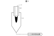
- FIG. 1 shows a schematic diagram of an apparatus for producing base silica powder.
- the circumference of the burner 1 having a concentric triple tube structure is further covered with a cylindrical outer cylinder 2, and if the cylindrical outer cylinder 2 is regarded as the fourth pipe of the burner 1, the burner 1 is the whole. It can also be regarded as having a quadruple pipe structure.
- the tubes constituting the concentric triple tube will be referred to as "central canal", “first annular tube” and “second annular tube” in order from the central portion to the outer edge.
- the burner 1 is installed in a reactor 3 in which a flame burns inside and silica is generated from a silicon compound inside the burner 1.
- the reactor 3 is provided with a jacket portion (not shown) on the outside so that forced cooling is possible, and has a structure capable of allowing a refrigerant to flow there.
- a silicon compound in a gaseous state and oxygen are mixed in advance and introduced into the central tube of the triple tube.
- an inert gas such as nitrogen may also be mixed.
- the silicon compound is liquid or solid at room temperature, it is vaporized by heating the silicon compound before use.
- silica is produced by the hydrolysis reaction of a silicon compound, fuels that generate water vapor when reacted with oxygen, such as hydrogen and hydrocarbons, are mixed together.
- a fuel for forming an auxiliary flame for example, hydrogen or hydrocarbon
- a fuel for forming an auxiliary flame for example, hydrogen or hydrocarbon
- an inert gas such as nitrogen may be mixed and introduced.
- oxygen may also be mixed.
- oxygen is introduced into the second annular tube adjacent to the outside of the first annular tube of the triple tube.
- This oxygen has two roles: silica formation by reaction with a silicon compound and auxiliary flame formation.
- an inert gas such as nitrogen may be mixed together.
- a mixed gas of an inert gas such as oxygen and nitrogen is introduced into the space formed by the outer wall of the triple tube and the inner wall of the cylindrical outer cylinder 2. Since it is easy to use air as the mixed gas, it is a preferable mode.
- a jacket portion is provided on the outside of the reactor 3 to circulate a refrigerant for removing combustion heat to the outside of the system. Since the combustion gas contains water vapor in most cases, it is burned in order to prevent dew condensation of water vapor and subsequent corrosion of the reactor 3 caused by absorption of the corrosive component in the combustion gas by the dewed water. It is a preferable mode that the refrigerant temperature before heat absorption (specifically, the temperature at which the refrigerant is introduced into the jacket) is 50 ° C. or higher and 200 ° C. or lower. Considering the ease of implementation, it is more preferable to use hot water having a temperature of 50 ° C. or higher and 90 ° C. or lower as the refrigerant.
- the difference between the temperature at which the refrigerant is introduced into the jacket (inlet temperature) and the temperature of the refrigerant discharged from the jacket (outlet temperature) is taken, and the temperature difference, the specific heat of the refrigerant, and the amount of the refrigerant flowing are taken. Therefore, the amount of heat absorbed by the refrigerant, that is, the amount of heat removed by the refrigerant from the reactor 3 can be grasped.
- R cmbts is less than 0.5, the amount of oxygen in the entire flame is small and the reaction does not proceed completely, so that the growth time of the particles is shortened. As a result, fine particles having a particle size of several tens of nm are generated, the median diameter D 50 is reduced, and the loose bulk density value is reduced.
- the median diameter D 50 is less than 300 nm.
- a compound that is gas, liquid, or solid at room temperature is used without particular limitation.
- cyclic siloxanes such as octamethylcyclotetrasiloxane, chain siloxanes such as hexamethyldisiloxane, alkoxysilanes such as tetramethoxysilane, and chlorosilanes such as tetrachlorosilane can be used as silicon compounds.
- silica powder it is preferable to use a silicon compound that does not contain chlorine in the molecular formula, such as the above-mentioned siloxane and alkoxysilane, because the chloride ion contained in the obtained silica powder can be significantly reduced.
- the silicon compound having a low content of various metal impurities can be easily obtained. Therefore, by using such a silicon compound having a low content of metal impurities as a raw material, the amount of metal impurities contained in the produced silica powder can be reduced. Further, by further purifying the silicon compound by distillation or the like and using it as a raw material, the amount of metal impurities contained in the produced silica powder can be further reduced.
- the recovery of the produced silica powder is not particularly limited, but it is performed by separating it from the combustion gas by filter separation using a sintered metal filter, ceramic filter, bag filter, etc., or by centrifugation using a cyclone, etc.
- the concentric triple tube used is a single tube, but as shown in the examples described later, it may be carried out in a multi-pipe system in which a plurality of concentric triple tubes are arranged.
- each concentric triple tube has the same structure and the same dimensions and the distance between the closest centers of the concentric triple tube is the same in terms of uniformity in obtaining the silica powder of the present invention. ..
- the cylindrical outer cylinder 2 may be installed so as to cover a plurality of concentric triple tube burners together.
- the silica powder produced by the silica powder manufacturing method which is the base material of the surface-treated silica powder of the present invention also has a spherical shape and a true density of about 2.2 g / cm 3 .
- the surface of the silica powder is modified by contacting the base silica powder obtained as described above with a surface treatment agent to obtain a surface-treated silica powder.
- the type of surface treatment reaction is not particularly limited, and a known method may be appropriately selected and adopted, and may be either a so-called dry type or wet type, or may be a batch type or a continuous type.
- the reactor may also be a fluidized bed type, a fixed bed type, a stirrer, a mixer, or a stationary type. Among them, in consideration of the uniformity and accelerating property of the reaction, it is more preferable to flow the silica powder in a fluidized bed type, a stirrer, a mixer or the like for the reaction.
- the surface of silica powder is modified by a surface treatment agent
- the surface of silica particles constituting the powder is treated by the surface treatment agent, and the surface morphology and chemistry are determined by the functional groups of the surface treatment agent. It refers to a state in which the composition, chemical reactivity, dispersibility in resin, etc. have been changed.
- a surface treatment agent is introduced into the surface of the silica powder to improve the dispersibility in the resin or impart water repellency. This makes it possible to improve the dispersibility of the silica powder in the resin, reduce the viscosity of the resin composition, and further improve the strength of the resin composition. Further, by imparting water repellency to the silica powder, it is often the case that the effect of suppressing moisture absorption during storage and improving storage stability and the like can be obtained.
- the degree of modification by introducing carbon atoms on the surface of the silica particles can be typically evaluated by measuring the carbon content of the silica powder.
- the carbon content may be measured using a trace carbon analyzer by the combustion oxidation method.
- the surface-treated silica powder sample is heated to 1350 ° C. in an oxygen atmosphere, and the obtained carbon amount is converted per unit mass to obtain it.
- the surface-treated silica powder to be measured is heated at 80 ° C. as a pretreatment to remove water adsorbed in the air by reducing the pressure in the system, and then subjected to the measurement of the carbon content.
- the surface treatment agent modifies only the surface of silica and does not modify the inside without communication holes (it cannot be contacted in the first place), so the increase in carbon content may be regarded as the surface carbon content.
- the surface carbon content of the surface-treated silica powder produced in the present invention is preferably 0.01% by mass or more and 2% by mass or less, more preferably 0.03% by mass or more and 1% by mass or less, and 0. It is particularly preferable that it is 03% by mass or more and 0.8% by mass or less.
- the surface treatment agent to be brought into contact with the base silica powder is not particularly limited as long as it is a known one used to impart a specific function to the silica surface, but silicone oil and silane coupling. It is preferably at least one surface treatment agent selected from agents, siloxanes and silicanes. In particular, it is preferably at least one surface treatment agent selected from the group consisting of silane coupling agents and silazanes.
- Specific examples of the surface treatment agent that can be used in the production method of the present invention include dimethyl silicone oil, methylphenyl silicone oil, methylhydrogen silicone oil, alkyl-modified silicone oil, amino-modified silicone oil, and epoxy-modified silicone oil.
- examples thereof include silicone oil, carboxyl-modified silicone oil, carbinol-modified silicone oil, methacryl-modified silicone oil, polyether-modified silicone oil, and fluorine-modified silicone oil.
- silane coupling agent a known silane coupling agent is appropriately used depending on the intended use.
- Examples of the silane coupling agent include those represented by the following formula (1).
- R n- Si-X (4-n) (1) (In the above formula (1), R is an organic group having 1 to 12 carbon atoms, X is a hydrolyzable group, and n is an integer of 1 to 3.)
- Examples of the organic group having 1 to 12 carbon atoms represented by R include methyl group, ethyl group, n-propyl group, hexyl group, octyl group, decyl group, phenyl group, vinyl group, octenyl group, 4-styryl group and the like.
- the plurality of Rs may be the same or different.
- Examples of the X include an alkoxy group having 1 to 3 carbon atoms such as a methoxy group, an ethoxy group and a propoxy group, and a halogen atom such as a chlorine atom, and among them, a methoxy group and an ethoxy group are preferable.
- n is 1 or 2
- the plurality of Xs may be the same or different, but are preferably the same.
- n is an integer from 1 to 3, it is preferably 1 or 2, and particularly preferably 1.
- silane coupling agent capable of introducing a hydrocarbon group having 1 to 10 carbon atoms into the silica surface in order to increase the dispersibility inside the resin and reduce the viscosity. That is, in the above formula (1), one in which R is a hydrocarbon group having 1 to 10 carbon atoms is preferably used.
- R is a hydrocarbon group having 1 to 8 carbon atoms
- R is a hydrocarbon group having 1 to 8 carbon atoms
- a silane coupling agent in which R is an aromatic hydrocarbon group having 6 to 8 carbon atoms is preferable, and specific examples thereof include phenyltrimethoxysilane.
- silane coupling agents shown in (1) a silane coupling agent capable of introducing an epoxy group or an amino group into the silica surface, that is, an organic group or amino having 3 to 12 carbon atoms in which at least one R has an epoxy group.
- a silane coupling agent having a group and having 1 to 12 carbon atoms, which is an organic group, is preferably used.
- a silane coupling agent capable of introducing a group having a carbon-carbon double bond at the terminal into the silica surface is preferably used. That is, in the above formula (1), a silane coupling agent in which R is a hydrocarbon group having 2 to 12 carbon atoms having a terminal double bond or an organic group having 3 to 12 carbon atoms in which R has a (meth) acryloyl group. A silane coupling agent is preferably used.
- a silane coupling agent such as vinyltrimethoxysilane, vinyltriethoxysilane, 4-styryltrimethoxysilane, which is a hydrocarbon group having 2 to 12 carbon atoms in which R has a terminal double bond, 3- ( Meta) acryloxypropyltrimethoxysilane, 3- (meth) acryloxypropyltriethoxysilane, 3- (meth) acryloxypropylmethyldimethoxysilane, 3- (meth) acryloxipropylmethyldiethoxysilane, (meth) acry
- R is an organic group having a (meth) acryloyl group and having 3 to 12 carbon atoms, such as loxyoctyltrimethoxysilane.
- siloxanes examples include polysiloxanes such as disiloxane, hexamethyldisiloxane, hexamethyldicyclotrisiloxane, octamethylcyclotetrasiloxane, decamethylcyclopentasiloxane, and polydimethylsiloxane.
- silazanes a commonly used compound having a Si—N (silicon-nitrogen) bond can be used without particular limitation, and is appropriately used depending on the required performance of the surface-treated silica powder and the like. You can select it and use it. Specifically, hexamethyldisilazane, 1,3-divinyl-1,1,3,3-tetramethyldisilazane, octamethyltrisilazane, hexa (t-butyl) disilazane, hexabutyldisilazan, hexaoctyldi.
- Cilazan 1,3-diethyltetramethyldisilazan, 1,3-di-n-octyltetramethyldisilazan, 1,3-diphenyltetramethyldisilazan, 1,3-dimethyltetraphenyldisilazan, 1,3- Diethyltetramethyldisilazane, 1,1,3,3-tetraphenyl-1,3-dimethyldisilazane, 1,3-dipropyltetramethyldisilazane, hexamethylcyclotrisilazane, hexaphenyldisilazane, dimethylaminotrimethyl Examples thereof include silazane, trisilazane, cyclotrisilazane, 1,1,3,3,5,5-hexamethylcyclotrisilazane and the like.
- alkyldisilazane is preferable because of its high reactivity with the silica surface, tetramethyldisilazane, hexamethyldisilazane, and heptamethyldisilazane are particularly preferable, and hexamethyldisilazane is most preferable.
- the base material silica powder is brought into contact with at least one surface treatment agent selected from the above-mentioned silicone oil, silane coupling agent, siloxanes and silazanes to bring the base material into contact with the base material.
- the surface of the silica powder is modified.
- the surface treatment method is roughly classified into a dry treatment and a wet treatment.
- the dry treatment is a method in which the base material silica powder is brought into contact with the surface treatment agent while maintaining the powder state, and since a large amount of solvent is not used, the cost is generally low and the method is suitable for mass production.
- the wet treatment is a method in which the base silica powder is dispersed in a solvent to form a dispersion liquid (including a paste-like one) and brought into contact with a surface treatment agent, and the silica surface can be modified more uniformly than the dry treatment.
- a dispersion liquid including a paste-like one
- the surface treatment is generally performed by the following procedure. That is, the base material silica powder is placed in the reaction vessel, and a predetermined amount of the surface treatment agent is added by dropping, spraying, or the like in a state where the base material silica powder is fluidized by shaking, stirring, or the like. At this time, it is usually aged to promote the reaction of the surface treatment agent with the silica surface. If the silica powder is taken out of the container after reacting with the surface treatment agent, it can be used as it is as a product.
- these procedures steps
- the surface treatment agent at least one selected from the above-mentioned silicone oil, silane coupling agent, siloxanes and silazanes can be used.
- the amount of the surface treatment agent used is not particularly limited and may be appropriately set from a known range according to the desired physical properties. However, if the amount is too small, the surface treatment becomes insufficient, and if it is too large, the amount present on the surface of the silica powder is excessive. Too much, and the tendency for agglomerates to form becomes stronger. Therefore, in the case of silicone oil, it is preferably 0.05 to 80 parts by mass, more preferably 0.1 to 60 parts by mass, and 1 to 20 parts by mass with respect to 100 parts by mass of the base material silica powder. Is most preferable.
- silane coupling agent it is preferably 0.05 to 80 parts by mass, more preferably 0.1 to 40 parts by mass, and most preferably 0.5 to 5 parts by mass.
- the amount is preferably 0.1 to 150 parts by mass, more preferably 1 to 120 parts by mass, and most preferably 2 to 60 parts by mass.
- the amount is preferably 0.1 to 150 parts by mass, more preferably 1 to 120 parts by mass, and most preferably 2 to 60 parts by mass.
- the surface treatment agent only one type may be used alone, or two or more types may be used in combination.
- the silica powder and various surface treatment agents are mixed to dry-treat the silica surface.
- the mixing means at this time is not particularly limited, but is preferably a mixing means that does not depend on the rotating body having the driving unit. Specific examples thereof include mixing by rotation and rocking of the container body and gas phase mixing by air. Examples of the mixing device having such a mixing means include a V blender, a locking mixer, a double cone type mixing device, an air blender that mixes airflow with air, and the like.
- the stirring energy received by the silica powder colliding with the stirring / mixing blades is usually as large as 50 J or more. Aggregated particles are likely to be generated in a powder having a small particle size.
- the device include a mixing device provided with stirring blades, mixing blades, and the like, such as a Henschel type mixing device and a Reedige mixer.
- the mixing device (dry surface treatment device) used in the present embodiment is provided with at least one crushing blade as a means for equalizing the particle size before and after the surface treatment of the silica powder.
- the crushing blade is a rotating body having a rotating shaft as a crushing means, and at least one piece extending in a direction perpendicular to the shaft, the shaft passing through the center of gravity of the blade or having the shaft as one end of the blade. It is a feather.
- the crushing energy of the crushing blade is preferably 0.3 to 10 J. If it is less than 0.1 J, the agglomerated particles cannot be sufficiently crushed and the agglomerated particles remain. On the other hand, if it exceeds 20 J, there arises a problem that the silica powder is likely to reaggregate.
- the crushing energy is remarkably small while the stirring energy of the stirring / mixing blade used as the mixing means is 50 J or more. Therefore, the crushing blade in the present embodiment is used as the mixing means. It is clearly distinguished from a rotating body having a drive unit, that is, a stirring / mixing blade.
- the crushing energy is calculated for each rotating shaft, and the moment of inertia of the crushing blade is first obtained.
- the crushing energy E (J) is calculated from the following equation using the moment of inertia calculated from (C), (D), and (E) and the rotation speed ⁇ (rad / s) of the crushing blade. Will be done.
- disintegration energy E (J) Iz ⁇ ⁇ 2/2
- the crushing energy can be obtained by a known mathematical formula according to the shape of each.
- the crushing energy per rotating shaft may be within the above range, and at least one rotating shaft with crushing blades may be installed, and a plurality of rotating shafts may be installed. In that case, the crushing energy of the crushing blades of each rotating shaft may be in the range of 0.3 to 10J.
- the material of the rotating shaft and the crushing blade is not particularly limited, and examples thereof include metals such as stainless steel and resins such as aluminum, polycarbonate, polypropylene, and acrylic. Among them, metals, especially stainless steel, have abrasion resistance. It is excellent and preferable.
- the shape of the crushing blade is not particularly limited, and a known one can be used. For example, a horizontal shape, an L-shape, a cylindrical shape, and the like can be mentioned.
- the size of the crushing blade is a size that can be accommodated in the apparatus, and is not particularly limited as long as the crushing energy is within the above range, but it is a case where a load is locally applied to the contents during rotation. However, it may be installed with a sufficient gap so as not to collide with the wall surface or other crushing blades.
- the length of the long side of the crushing blade is 300 mm. It is preferable to do as follows.
- the thickness of the crushing blade is not particularly limited, but is preferably 1 to 5 mm.
- the rotation speed of the crushing blade is also directly related to the crushing energy as described above. Although it depends on the size of the crushing blade described above, it is preferably 50 to 300 (rad / s). If the rotation speed is too slow, the crushing effect becomes small, and conversely, if it exceeds 310 (rad / s), the crushing energy tends to exceed 10 J. Further, by setting the rotation speed to a small value, the mechanical load tends to be suppressed.
- the length of the long side is taken into consideration in consideration of the material of the crushing blade, that is, the weight so that the crushing energy per rotating shaft obtained from the above (C) to (F) and the like is 0.3 to 10 J.
- the length and thickness of the short side, the number of crushing blades, and the number of rotations may be relatively selected within the above ranges.
- the location where the rotation shaft of the crushing blade is installed is not particularly limited as long as the crushing blade is located at the dust contact portion in the apparatus.
- the inner surface of the body and the inner surface of the body can be contacted with the powder at any part of the space inside the mixer. It can be installed at any of the inner wall surfaces at both ends.
- the flow of silica powder due to the air flow should be taken into consideration, and the crushing blades should be installed so that they come into contact with the powder efficiently. It can be installed at any location.
- the size of the mixing device used for the mixing is not particularly limited, but generally, a mixing device having an internal volume of 10 L to 4 m 3 is preferably used.
- the silica powder as a base material is supplied to the surface treatment apparatus.
- the amount of the base material silica powder supplied is not particularly limited as long as the supplied base material can be mixed, but in consideration of general processing efficiency, it is preferably 1 to 6 with respect to the internal volume of the mixing device. It is relatively, more preferably 30 to 50%.
- the surface treatment agent is supplied to the mixing device to which the base material silica powder is supplied.
- the supply amount of the surface treatment agent is as described above.
- the surface treatment agent may be diluted with a solvent and then mixed with silica powder.
- the solvent used is not particularly limited as long as it dissolves the surface treatment agent. Any solvent that does not affect the functional groups of the surface treatment agent is not particularly limited, and a known solvent can be used.
- alcohols such as methyl alcohol, ethyl alcohol, 1-propyl alcohol and 2-propyl alcohol are preferably used, but organic solvents other than alcohols can also be used.
- the dilution ratio when diluting with a solvent is not particularly limited, but is generally used after diluting about 2 to 5 times.
- additives such as a polymerization inhibitor, a polymerization inhibitor, and an ultraviolet absorber may be used. These are not particularly limited, and known ones can be used.
- the method of adding the surface treatment agent is not particularly limited.
- the whole amount may be added at one time, or may be added continuously or intermittently while mixing, but when the amount of the base silica powder to be treated is large or the amount of the surface treatment agent is large. Is preferably added continuously or intermittently while mixing.
- the addition of the surface treatment agent is preferably carried out by dropping or spraying using a pump or the like. A known spray nozzle or the like can be preferably used for the spray.
- the surface treatment agent is gaseous, it can be introduced by blowing it into the reactor.
- the supply rate of the surface treatment agent is not particularly limited, and it may be determined in consideration of the amount of the surface treatment agent used and the like.
- the supply rate can be determined as follows. That is, an experiment was conducted in which the colorant was supplied while preliminarily stirring the base material silica powder in the mixing device, and the supply rate to the extent that the base material silica powder was uniformly colored was obtained, and the obtained colorant supply speed was obtained. The supply speed is about half of the above. Here, the reason why the supply rate is set to about half of the colorant supply rate is to ensure uniform mixing.
- the time required for uniform coloring varies depending on the stirring / fluidizing method, the capacity of the mixing device, etc., but it is generally supplied at 0.01 to 10 ml / min per 100 g of the base silica powder. It is preferable to set each condition as described above, and it is particularly preferable to supply at 0.03 to 5 ml / min. Especially when the amount of surface treatment agent used is large, if the supply speed is slow, the treatment time will be long and the productivity will be poor. It becomes large and agglomerated particles are easily generated in the silica powder.
- the atmosphere inside the mixing device is not particularly limited, but an inert gas such as nitrogen, helium, or argon is preferably used. By doing so, hydrolysis by water and oxidative decomposition by oxygen can be suppressed.
- an inert gas such as nitrogen, helium, or argon
- the temperature at which the surface treatment agent is supplied, mixed with the base silica powder and brought into contact with the powder is not particularly limited, but if the temperature is too high, the surface treatment agent may polymerize depending on the type, or the surface treatment agent may be used. Since it vaporizes rapidly, it is generally about -10 to 40 ° C.
- the mixing may be performed as long as the surface treatment agent is uniformly mixed with the silica powder, and the time required to supply the entire surface treatment agent from the supply rate and the amount of the surface treatment agent to be supplied (that is, necessary for mixing). Time) is required.
- agglomerated particles are generated due to uneven distribution of the surface treatment agent and strong mixing energy.
- the formation of agglomerated particles in the silica powder is suppressed.
- the generated agglomerated particles are efficiently crushed by the crushing blades before becoming strong agglomerated particles, so that a surface treatment agent is added and mixed. Even after that, the silica powder maintains a state in which there are extremely few agglomerated particles. Further, when such a mixing device is used, even if the surface treatment agent is excessively supplied, the surface treatment agent is uniformly treated on the particle surface and the agglomerated particles are generated. A reduced surface-treated silica powder is obtained.
- the silica powder is surface-treated by adding and mixing the above-mentioned surface treatment agent, and further aging treatment after the operation is a reaction between the reactive group of the surface treatment agent adhering to the surface of the silica powder and the silica surface. It is preferable to proceed sufficiently.
- the aging treatment is carried out with or without heating. In the aging treatment, when an apparatus having a heating means is used as the mixing apparatus, the apparatus can be used as it is and heat is applied while stirring and fluidizing to perform heating. Alternatively, the silica powder sufficiently mixed with the surface treatment agent can be taken out, heated by another device, and heated with or without stirring or the like.
- the atmospheric gas in another aging device is not particularly limited, but it is preferable to use an inert gas atmosphere such as nitrogen, helium, or argon as in the mixing device.
- an inert gas atmosphere such as nitrogen, helium, or argon
- the temperature at which the aging treatment is performed is too low, the progress of the reaction will be slowed down, resulting in a decrease in production efficiency, and if it is too high, the decomposition of the surface treatment agent and the formation of agglomeration due to a rapid polymerization reaction will be promoted. Therefore, although it depends on the surface treatment agent used, it is generally preferable to carry out the treatment at 25 to 300 ° C., preferably 40 to 250 ° C. In this temperature condition range, the vapor pressure of the surface treatment agent in the mixing apparatus is preferably 1 kPa or more, and further, it is preferable to heat at a temperature at which the vapor pressure of the surface treatment agent is 10 kPa or more. In the surface treatment of the silica powder, the pressure in the mixing device may be normal pressure, pressurized pressure, or negative pressure.
- the aging treatment time may be appropriately determined according to the reactivity of the surface treatment agent to be used. It is usually possible to obtain a sufficient reaction rate within 1 hour or more and 500 hours or less. After the aging treatment is completed, it may be taken out from the container used for aging, filled in a container or bag for storage, and stored or shipped.
- the surface treatment is generally performed by the following procedure. That is, a dispersion liquid is prepared by mixing the base material silica powder and the solvent. A predetermined amount of surface treatment agent is added while stirring in the reaction vessel, and after reacting for a predetermined time, solid-liquid separation is performed to recover the solid content (surface treatment silica), and then drying is performed to obtain the surface treatment silica powder. Obtainable. At the time of solid-liquid separation, it is also preferable to add a coagulant to increase the separation ability.
- these procedures steps
- the surface treatment agent shown in the surface treatment silica powder production method by the dry surface treatment can be preferably used. That is, at least one selected from silicone oil, silane coupling agent, siloxanes and silazanes is preferable.
- the surface treatment agent only one type may be used alone, or two or more types may be used in combination.
- the solvent used for the wet surface treatment is not particularly limited, and water and a known organic solvent can be used. At least one selected from water and known organic solvents is appropriately selected depending on the type of surface treatment agent used.
- organic solvent examples include alcohols such as methyl alcohol, ethyl alcohol, 1-propyl alcohol, 2-propyl alcohol and butyl alcohol; ethers such as tetrahydrofuran and dioxane; amides such as dimethylformamide, dimethylacetamide and N-methylpyrrolidone.
- alcohols such as methyl alcohol, ethyl alcohol, 1-propyl alcohol, 2-propyl alcohol and butyl alcohol
- ethers such as tetrahydrofuran and dioxane
- amides such as dimethylformamide, dimethylacetamide and N-methylpyrrolidone.
- Sulfoxides such as dimethyl sulfoxide and sulfolane
- Hydrocarbons such as hexane, toluene and benzene
- Chlorinated hydrocarbons such as methylene chloride and chloroform
- Ketones such as acetone and methyl ethyl ketone
- Estels such as ethyl acetate, Examples thereof include nitriles such as acetonitrile.
- the water and the organic solvent may be used alone or as a mixture of two or more kinds of solvents. It may be selected in consideration of its solubility, reactivity, stability of functional groups and the like according to the type of surface treatment agent to be used.
- the water and the organic solvent are uniformly mixed.
- an organic solvent that is uniformly mixed with water alcohols such as methyl alcohol, ethyl alcohol, 1-propyl alcohol, 2-propyl alcohol and butyl alcohol; ethers such as tetrahydrofuran and dioxane; Examples thereof include amide compounds such as dimethylformamide, dimethylacetamide, and N-methylpyrrolidone.
- ⁇ Wet surface treatment equipment> As the surface treatment apparatus used in this embodiment, a known stirrer or mixer is used without particular limitation.
- stirring blades of the stirrer known ones are used without particular limitation, but typical ones are inclined paddle blades, turbine blades, three swept blades, anchor blades, full zone blades, and twin star blades. , Max blend wings, etc.
- the reactor having such a stirrer is particularly limited to a reactor having a hemispherical or flat-bottomed or round-bottomed cylindrical shape, and a reactor in which a baffle plate is installed in these reactors. Can be used without.
- the material of the reactor is not particularly limited, and a metal material such as glass or stainless steel (including a glass-coated or resin-coated one) or a resin material can be used. In order to obtain a high-purity surface-treated silica powder, it is preferable that the material has excellent wear resistance.
- the base material silica powder and the solvent as described above are supplied to the surface treatment apparatus to prepare a silica dispersion liquid.
- the amount of the solvent to be supplied is preferably 50 to 2000 parts by mass, more preferably 80 to 1000 parts by mass with respect to 100 parts by mass of the base silica powder.
- the addition method is not particularly limited.
- the surface treatment agent is a liquid having a low viscosity at normal temperature and pressure, it may be added to the dispersion liquid.
- the surface treatment agent may be added all at once, or may be added separately.
- the method of adding is not particularly limited, and it may be dropped or sprayed in the form of a spray.
- the surface treatment agent is a high-viscosity liquid or a solid, it can be added to a suitable organic solvent to prepare a solution or a dispersion, and then added in the same manner as in the case of a low-viscosity liquid.
- the organic solvent used for dilution a known solvent that does not affect the functional groups of the surface treatment agent used can be used.
- alcohols such as methyl alcohol, ethyl alcohol, 1-propyl alcohol and 2-propyl alcohol are preferably used, but organic solvents other than alcohols can also be used.
- the dilution ratio when diluting with a solvent is not particularly limited, but is generally used after diluting about 2 to 5 times.
- the surface treatment agent is in the form of a gas, it can be added by blowing it into the liquid in the form of fine bubbles.
- the treatment temperature at the time of surface treatment may be determined in consideration of physical characteristics such as the freezing point and boiling point of the solvent used and the reactivity of the surface treatment agent. However, if the treatment temperature is too low, the reaction proceeds slowly. If the temperature is too high, the operation is complicated, so the temperature is preferably 10 to 150 ° C, more preferably 20 to 100 ° C.
- the treatment time when performing the surface treatment is not particularly limited, and may be determined in consideration of the reactivity of the surface treatment agent to be used, the treatment temperature, and the like.
- the treatment time is preferably 0.1 to 48 hours, more preferably 0.5 to 24 hours, in consideration of both the sufficient progress of the surface treatment reaction and the shortening of the process time.
- the treatment time is the time from the start of addition of the surface treatment agent to the addition of the coagulant described later, or the solid-liquid separation when the coagulant is not used.
- a known catalyst When performing surface treatment, a known catalyst can be used depending on the type of surface treatment agent.
- examples of such a catalyst include inorganic acids such as hydrochloric acid, nitrate and sulfuric acid, acidic catalysts such as acetic acid, oxalic acid and citric acid, amine compounds such as ammonia, trimethylamine and triethylamine, and alkaline catalysts such as alkali metal hydroxide.
- inorganic acids such as hydrochloric acid, nitrate and sulfuric acid
- acidic catalysts such as acetic acid, oxalic acid and citric acid
- amine compounds such as ammonia, trimethylamine and triethylamine
- alkaline catalysts such as alkali metal hydroxide.
- the amount of catalyst used may be appropriately determined in consideration of the reactivity of the surface treatment agent.
- the abundance of the catalyst in the reaction solution is preferably 0.01 to 50 parts by mass with respect to 100 parts by mass of the surface treatment agent to be used, and is used in the range of 0.01 to 35 parts by mass. It is more preferable to do so.
- the filter As the filter, a filter having a mesh size that allows surface-treated primary particles to pass through and does not allow coarse particles or agglomerates significantly larger than the primary particles to pass through is used.
- the surface-treated silica powder is taken out by solid-liquid separation, but a known coagulant may be added to the dispersion prior to the solid-liquid separation.
- a coagulant By adding a coagulant to the dispersion, weak aggregates of the surface-treated silica powder are formed in the dispersion.
- the agglomerates can be stably present in the dispersion due to the presence of the coagulant or its derivative present in the dispersion, and therefore can be easily recovered by filtration or the like.
- ammonium salts such as ammonium carbonate, ammonium hydrogencarbonate and ammonium carbamate can be preferably used. Since these coagulants are easily decomposed and removed by a slight heating, there is an advantage that a high-purity surface-treated silica powder can be easily produced.
- the ratio of the coagulant used and the method of adding the coagulant can be set as follows according to the type of the coagulant used.
- the ratio of the coagulant used is set by considering the balance between the degree of formation of weak aggregates of the surface-treated silica powder in the dispersion liquid and the waste of using an unreasonably large amount of raw materials.
- the ratio of the coagulant to be used is preferably 0.001 part by mass or more, preferably 0.001 to 50 parts by mass, based on 100 parts by mass of the base material silica powder contained in the dispersion liquid. It is more preferably 0.1 to 20 parts by mass, and further preferably 0.5 to 10 parts by mass.
- the above-mentioned coagulant such as ammonium carbonate, ammonium hydrogencarbonate or ammonium carbamate is usually a solid, but in the present embodiment, it may be added in a solid state or in a solution state dissolved in an appropriate solvent. It may be added.
- the solvent used when adding in a solution state is not particularly limited as long as it dissolves the coagulant to be used, but from the viewpoint of high dissolving ability and easy removal after solid-liquid separation. Therefore, it is preferable to use water.
- the concentration of the coagulant when used in a solution state is not particularly limited as long as it is within the dissolution range, but if the concentration is too low, the amount of the solution used increases and it is uneconomical, so the concentration is set to 0.5 to 15% by mass. It is preferable, and it is particularly preferable that it is 1 to 12% by mass. Further, since the effect of the coagulant can be easily obtained, it is preferable that the dispersion liquid after adding the coagulant contains 5% by mass or
- the coagulant may be used alone or in combination of two or more.
- ammonium hydrogen carbonate and ammonium carbamate which is commercially available as so-called “ammonium carbonate"
- ammonium carbonate a mixture of ammonium hydrogen carbonate and ammonium carbamate, which is commercially available as so-called “ammonium carbonate”
- ammonium carbonate a mixture of ammonium hydrogen carbonate and ammonium carbamate, which is commercially available as so-called “ammonium carbonate”
- the total usage ratio of ammonium hydrogen carbonate and ammonium carbamate, the type of solvent used when this is added as a solution, and the concentration of the solution are in the case of ammonium carbonate, ammonium hydrogen carbonate or ammonium carbamate. It is the same as the above-mentioned place.
- the temperature of the surface-treated silica powder dispersion liquid when the coagulant is added is preferably ⁇ 10 to 60 ° C., more preferably 10 to 50 ° C.
- the aging time is preferably 0.5 to 72 hours, and particularly preferably 1 to 48 hours.
- the temperature of the dispersion liquid at the time of aging is not particularly limited, and it can be carried out in the same temperature range as the preferable temperature at the time of adding the coagulant, and if it is carried out at the same temperature as when the coagulant is added. Sufficient.
- the solid-liquid separation method for extracting the surface-treated silica from the dispersion liquid after the surface treatment or the dispersion liquid to which the coagulant is added after the surface treatment is not particularly limited to known methods such as a solvent distillation method, a centrifugation method, and a filtration method. Can be used. It is preferable to select the filtration method because it is easy to obtain a surface-treated silica powder that is easily melted after drying and because it is easy to operate.
- the filtration method is not particularly limited, and a known device such as vacuum filtration, centrifugal filtration, or pressure filtration may be selected.
- filter paper used in the filtration method can be used without particular limitation as long as they are industrially available.
- the scale of the separation device (filter), the average particle size of the silica to be recovered, and the like may be appropriately selected.
- Surface-treated silica is recovered as cake by solid-liquid separation by filtration method or the like.
- a suitable solvent such as water or alcohol
- the solvent used in the surface treatment step and the unreacted surface treatment agent can be decomposed or removed.
- the drying temperature is not particularly limited, but if the temperature is too high, the functional groups introduced into the silica surface are decomposed, which is not preferable.
- the coagulant can be easily removed by thermal decomposition by setting the drying temperature to 35 ° C. or higher, and the surface-treated silica powder can be easily crushed. It can be further improved. Therefore, the drying temperature is preferably 35 to 200 ° C., more preferably 80 to 180 ° C., and particularly preferably 100 to 150 ° C.
- the drying method is not particularly limited, and known methods such as blast drying and vacuum drying can be adopted. Since it tends to be more easily crushed, it is preferable to adopt vacuum drying.
- the drying time is not particularly limited and may be appropriately selected depending on the drying conditions, for example, the drying temperature and pressure, but generally, the surface-treated silica powder is sufficiently dried by setting it to about 2 to 48 hours. Can be obtained.
- the surface-treated silica powder obtained after drying may be lightly agglomerated, it may be crushed with a jet mill, a ball mill, or the like as necessary to make a final product.
- the crushing can also be carried out in the above-mentioned dry treatment.
- the surface-treated silica powder obtained by the above-mentioned production method of the present invention has a cumulative 50% mass diameter D 50 (hereinafter, also referred to as “median diameter D 50”) of the mass reference particle size distribution obtained by the laser diffraction / scattering method of 300 nm. It is preferably 5 nm or more and 500 nm or less. If it is larger than the above range, the viscosity of the resin composition is low, but the silica particle size is too large with respect to the gap, and as a result, voids are generated at the time of permeation of the gap, which causes molding failure. That is, sufficient narrow gap permeability cannot be obtained. On the other hand, if it is smaller than the above range, the viscosity of the resin composition becomes high, which is not preferable.
- the mass-based particle size distribution by the laser diffraction / scattering method 0.1 g of the surface-treated silica powder is weighed with an electronic balance, about 40 mL of ethanol is added, and the surface-treated silica powder is dispersed at an output of 40 W and a treatment time of 2 minutes using an ultrasonic homogenizer. This is the mass-based particle size distribution of the dispersed particles obtained.
- the particle size characteristics of the base silica powder are measured by the centrifugal sedimentation method, and the particle size characteristics of the silica powder after the surface treatment are measured by the laser diffraction / scattering method.
- the base silica powder that has not been surface-treated is highly hydrophilic, so its particle size characteristics can be measured more accurately by measuring it by the centrifugal sedimentation method using water as a dispersion medium, while it is hydrophobic by surface treatment.
- the laser diffraction / scattering method which generally uses an organic solvent such as alcohol such as ethanol as a dispersion medium, is suitable for the surface-treated silica powder having a higher degree of conversion.
- the characteristic that the particle size distribution is appropriately adjusted is that ⁇ (D 90- D 50 ) / D 50 ⁇ x 100 is 25% or more in relation to the cumulative 50% mass diameter D 50 and the cumulative 90% mass diameter D 90. And it is specified by 40% or less.
- the range is different from that of the base material silica powder because of the difference between the centrifugal sedimentation method and the laser diffraction / scattering method, and the laser diffraction / scattering method measures the particle size distribution relatively narrowly.
- the particle size distribution represented by the above formula exceeds 40%, it indicates that there are many coarse particles, which causes voids in the case of a resin composition or the like.
- ⁇ (D 90- D 50 ) / D 50 ⁇ x 100 is 25% or more and 35% or less.
- the surface-treated silica powder obtained in the present invention preferably has a geometric standard deviation ⁇ g of the volume-based particle size distribution obtained by the laser diffraction method in the range of 1.20 or more and 1.40 or less.
- ⁇ g geometric standard deviation
- the geometric standard deviation ⁇ g is small, it can be said that the particle size distribution is narrow, and therefore the amount of coarse grains is reduced.
- the geometric standard deviation ⁇ g is a geometry calculated from the lognormal distribution fitting (minimum square method) of the mass-based particle size distribution obtained by the laser diffraction / scattering method within a range of cumulative frequency of 10 wt% or more and 90 wt% or less. Standard deviation.
- the treatment is carried out by the method as described above so as not to cause aggregation due to the surface treatment, it is possible to obtain the surface-treated silica powder having each particle size characteristic as described above by using the base material silica powder. ..
- the surface-treated silica powder obtained by the production method of the present invention preferably has an element content of iron, nickel, chromium, and aluminum of less than 1 ppm because short circuits between metal wirings in the semiconductor device can be reduced. ..
- the surface-treated silica powder obtained by the production method of the present invention has a sodium ion, potassium ion, chloride ion, and ion content of each of less than 1 ppm, which is measured by the hot water extraction method, for the semiconductor device. This is preferable because it can reduce malfunction and corrosion of metal wiring in the semiconductor device.
- the above-mentioned base material silica powder is used, the above-mentioned metal-containing material is not used as the surface treatment agent, and the operation is performed while paying attention to general metal impurity mixing, the above-mentioned various metal impurities are used. A surface-treated silica powder with a small amount of impurities can be obtained.
- the particles constituting the surface-treated silica powder obtained by the production method of the present invention are spherical.
- the shape can be grasped by, for example, observing with an electron microscope.
- surface treatment does not change the shape that can be grasped by electron microscope observation, so if spherical silica powder is used as the base silica powder, the surface-treated silica will also be spherical.
- the use of the surface-treated silica powder obtained by the production method of the present invention as described above is not particularly limited.
- it can be used as a filler for a semiconductor encapsulant or a semiconductor mounting adhesive, a filler for a die attach film or a die attach paste, or a filler for a resin composition such as an insulating film for a semiconductor package substrate.
- the surface-treated silica powder obtained in the present invention can be suitably used as a filler for a resin composition for high-density mounting.
- the type of resin containing the surface-treated silica powder is not particularly limited.
- the type of resin may be appropriately selected depending on the desired use, and examples thereof include epoxy resin, acrylic resin, silicone resin, olefin resin, polyimide resin, polyester resin and the like.
- the surface-treated silica powder may be mixed with various resins and other components to be blended if necessary.
- the surface-treated silica powder obtained by the production method of the present invention can be dispersed in a dispersion medium to form a dispersion.
- the dispersion may be a liquid dispersion, or may be a solid such as a solidified dispersion.
- the solvent used for dispersing the surface-treated silica powder is not particularly limited as long as it is a solvent in which the surface-treated silica powder can be easily dispersed.
- a solvent for example, water and an organic solvent such as alcohols, ethers and ketones can be used.
- the alcohols include methanol, ethanol, 2-propyl alcohol and the like.
- a mixed solvent of water and any one or more of the above organic solvents may be used.
- various additives such as dispersants such as surfactants, thickeners, wetting agents, defoaming agents or acidic or alkaline pH adjusting agents are used. May be added. Also, the pH of the dispersion is not limited.
- a resin composition having a better dispersed state of the silica powder in the resin can be obtained than when the dried silica powder is mixed with the resin.
- Good dispersion of particles means that the number of agglomerated particles in the resin composition is reduced. Therefore, the performances of both the viscosity characteristics and the crevice permeability of the resin composition containing the silica powder of the present invention as a filler can be further improved.
- the surface-treated silica powder obtained in the present invention contains abrasive grains of CMP (Chemical Mechanical Polishing) abrasives, abrasive grains for grindstones used for grinding, toner external additives, additives for liquid crystal sealants, and dental fillers. Alternatively, it can also be used as an inkjet coating agent or the like.
- CMP Chemical Mechanical Polishing
- the methods for measuring and evaluating the physical properties of the base silica powder and the surface-treated silica powder are as follows.
- BET Specific Surface Area S (m 2 / g) was measured by the nitrogen adsorption BET 1-point method using a specific surface area measuring device SA-1000 manufactured by Shibata Rikagaku Co., Ltd.
- the absorbance ⁇ 700 of the obtained aqueous suspension having a silica concentration of 0.075 wt% with respect to light having a wavelength of 700 nm was measured using a spectrophotometer V-630 manufactured by JASCO Corporation.
- the absorbance ⁇ 460 of the aqueous suspension with respect to light having a wavelength of 460 nm was also measured, and the dispersibility index n defined by ln ( ⁇ 700 / ⁇ 460 ) / ln (460/700) was also obtained. ..
- Mass-based particle size distribution by centrifugal sedimentation method A water suspension having a silica concentration of 1.5 wt% obtained by the above method was subjected to CPS Instruments Inc. The mass-based particle size distribution was measured using a disk centrifugal particle size distribution measuring device DC24000 manufactured by the same manufacturer. The measurement conditions were a rotation speed of 9000 rpm and a silica true density of 2.2 g / cm 3 .
- a cumulative 50% mass diameter D 50 and a cumulative 90% mass diameter D 90 were calculated from the obtained mass-based particle size distribution. Further, the lognormal distribution fitting was performed in the range of the cumulative frequency of 10% by mass or more and 90% by mass or less with respect to the obtained mass-based particle size distribution, and the geometric standard deviation ⁇ g was calculated from the fitting.
- a cumulative 50% mass diameter D 50 and a cumulative 90% mass diameter D 90 were calculated from the obtained mass-based particle size distribution. Further, the lognormal distribution fitting was performed in the range of the cumulative frequency of 10% by mass or more and 90% by mass or less with respect to the obtained mass-based particle size distribution, and the geometric standard deviation ⁇ g was calculated from the fitting. In addition, the presence or absence of a signal of 5 ⁇ m or more was confirmed for coarse particles of 5 ⁇ m or more in the laser diffraction / scattering method.
- the loose bulk density and the firm bulk density were measured using a powder property evaluation device powder tester PT-X type manufactured by Hosokawa Micron Co., Ltd.
- the "loose bulk density" in the present invention refers to the bulk density in a sparsely filled state, in which a sample is uniformly supplied from 18 cm above the cylindrical container to a cylindrical container (material: stainless steel) having a volume of 100 mL, and the upper surface is scraped off. Measured by weighing.
- hard bulk density refers to the bulk density when tapping is added to this to make it densely packed.
- tapping refers to an operation in which a container filled with a sample is repeatedly dropped from a constant height to give a light impact to the bottom to densely fill the sample.
- a cap equipment of the powder tester manufactured by Hosokawa Micron Co., Ltd. below
- powder is added to the upper edge.
- tapping is performed 180 times. After completion, the cap is removed, the powder is ground on the upper surface of the container and weighed, and the bulk density in this state is defined as the bulk density.
- silica powder or surface-treated silica powder 5 g is added to 50 g of ultrapure water and heated at 120 ° C. for 24 hours using a fluororesin decomposition container to extract hot water of ions.
- Ultrapure water and silica powder or surface-treated silica powder were weighed to 0.1 mg units. Subsequently, the solid content was separated using a centrifuge to obtain a measurement sample. The same operation was performed only with ultrapure water, and this was used as a blank sample for measurement.
- the concentrations of sodium ion, potassium ion, and chloride ion contained in the measurement sample and the blank sample were quantified using the ion chromatography system ICS-2100 manufactured by Nippon Dionex Co., Ltd., and calculated using the following formula.
- C Silicona (C Sample- C Blank ) x MPW / M Silicona
- C Silica Ion concentration in silica (ppm)
- C Sample Ion concentration (ppm) in the measurement sample
- C Blank Ion concentration in blank sample (ppm)
- MPW Ultrapure water amount (g)
- M Silica Silica weight (g) The C Blank of each ion was 0 ppm.
- the carbon content (mass%) of the surface-treated silica powder was measured by the combustion oxidation method (EMIA-511, manufactured by HORIBA, Ltd.). Specifically, the surface-treated silica powder sample was heated to 1350 ° C. in an oxygen atmosphere, and the obtained carbon content was obtained by converting it per unit mass. The surface-treated silica powder to be measured is heated at 80 ° C. as a pretreatment to remove water adsorbed in the air by reducing the pressure in the system, and then subjected to the measurement of the carbon content.
- EMIA-511 combustion oxidation method
- the obtained resin composition was defoamed for 30 minutes under reduced pressure using a vacuum pump (TSW-150 manufactured by Sato Vacuum Co., Ltd.).
- the kneaded resin composition was measured for initial viscosity ( ⁇ 1 ) and viscosity after 1 week ( ⁇ 2 ) at a shear rate of 1 s -1 using a rheometer (HAAKE MARS40, manufactured by Thermo Fisher Scientific).
- the measurement temperatures were 25 ° C and 110 ° C, and the sensor used was C35 / 1 (cone plate type diameter 35 mm, angle 1 °, material titanium).
- the rate of change in viscosity with time was calculated from the following equation.
- the resin composition was stored at 25 ° C.
- Viscosity change rate over time [%] (( ⁇ 2- ⁇ 1 ) / ⁇ 1 ) ⁇ 100
- the hand-kneaded resin composition was pre-kneaded with a rotating and revolving mixer (manufactured by THINKY, Awatori Kentarou AR-500) (kneading: 1000 rpm, 8 minutes, defoaming: 2000 rpm, 2 minutes).
- the pre-kneaded resin composition was stored in a constant temperature water bath at 25 ° C. and then kneaded using three rolls (BR-150HCV roll diameter ⁇ 63.5 manufactured by IMEX).
- the kneading conditions were such that the kneading temperature was 25 ° C., the distance between rolls was 20 ⁇ m, and the number of kneading was 8 times.
- the obtained resin composition was defoamed for 30 minutes under reduced pressure using a vacuum pump (TSW-150 manufactured by Sato Vacuum Co., Ltd.).
- the kneaded resin composition was measured for initial viscosity ( ⁇ 1 ) and viscosity after 1 day ( ⁇ 2 ) at a shear rate of 1 s -1 using a rheometer (HAAKE MARS40, manufactured by Thermo Fisher Scientific).
- the measurement temperature was 25 ° C.
- the sensor used was C35 / 1 (cone plate type diameter 35 mm, angle 1 °, material titanium).
- the resin composition was stored at 25 ° C.
- Viscosity change rate over time [%] (( ⁇ 2- ⁇ 1 ) / ⁇ 1 ) ⁇ 100
- Oxygen concentration (number of moles of oxygen introduced into the central canal) / (number of moles of oxygen introduced into the central canal + number of moles of nitrogen introduced into the central canal) x 100 RO (Number of moles of oxygen introduced into the central canal) / (16 x number of moles of raw material introduced into the central canal) R SFL (Number of moles of hydrogen introduced into the first annular tube) / (32 x number of moles of raw material introduced into the central tube) Amount of heat removed (specific heat of hot water) x (amount of hot water introduced) x (hot water outlet temperature-hot water inlet temperature)
- the hot water inlet temperature 75 ° C.
- the outlet and the inlet are a hot water discharge port and an introduction port in the jacket portion (not shown).
- Amount of heat of combustion (number of moles of introduced raw material x amount of heat of combustion of raw material) + (number of moles of introduced hydrogen x amount of heat of combustion of hydrogen)
- Table 1 will be described by describing the central canal, the first annular tube, and the second annular tube of the concentric triple tube as simply the central canal, the first annular tube, and the second annular tube, respectively.
- ⁇ is the distance between the center of the central canal and the center of another central canal (the length of the side of the equilateral triangle)
- d is the inner diameter of the central canal
- D is the center of the central canal and the inner wall of the reactor. The shortest distance between and. The larger the D / d, the greater the distance between the flame and the inner wall of the reactor.
- octamethylcyclotetrasiloxane was burned as described below to produce a base silica powder.
- Table 1 shows the production conditions and the characteristics of the obtained base silica powder.
- the contents of Fe, Ni, Cr, Al, Na + , K + and Cl ⁇ were all less than 1 ppm.
- Production Examples 2 to 12 The production conditions were changed as shown in Table 1, and the base silica powder was produced in the same manner as in Production Example 1.
- Table 1 shows the physical characteristics of the base material silica powder obtained. In each of the examples, the contents of Fe, Ni, Cr, Al, Na + , K + and Cl ⁇ were all less than 1 ppm.
- Example 1 A locking mixer (RM-30 manufactured by Aichi Electric Co., Ltd.) was used as a surface treatment mixer, and phenyltrimethoxysilane (manufactured by Shinetsu Silicone) was used as a surface treatment agent for the base silica powder (2.97 kg) obtained in Production Example 1.
- KBM-103, 14.70 g, 25 ⁇ mol / g) was supplied at a rate of 2 mL / min using a perista pump (SJ-1211 II-H manufactured by ATTA), and the temperature was raised from room temperature to 40 ° C. in 20 minutes while mixing. It was maintained at 40 ° C. for 60 minutes. Then, the temperature was raised to 150 ° C. for 60 minutes and then maintained at 150 ° C. for 180 minutes. Aging and mixing were stopped and cooled to obtain a surface-treated silica powder.
- a perista pump SJ-1211 II-H manufactured by ATTA
- Table 2 shows the characteristics of the surface-treated silica powder obtained in Example 1.
- the contents of Fe, Ni, Cr, Al, Na + , K + and Cl ⁇ were all less than 1 ppm.
- Example 2 A locking mixer (RM-30 manufactured by Aichi Electric Co., Ltd.) was used as a surface treatment mixer, and hexamethyldisilazane (manufactured by Shinetsu Silicone) was used as a surface treatment agent for the base silica powder (2.24 kg) obtained in Production Example 1.
- SZ-31, 16.76 g, 46.5 ⁇ mol / g) was supplied at a rate of 2.5 mL / min using a perista pump (SJ-1211 II-H manufactured by ATTA), and mixed from room temperature to 150 ° C. in 60 minutes. After the temperature was raised, it was maintained at 150 ° C. for 120 minutes. Then, aging and mixing were stopped and cooled to obtain a surface-treated silica powder.
- Table 2 shows the characteristics of the surface-treated silica powder obtained in Example 2.
- the contents of Fe, Ni, Cr, Al, Na + , K + and Cl ⁇ were all less than 1 ppm.
- Example 3 1014 g of water and 424 g of the base material silica powder obtained in Production Example 1 were placed in a 2 L separable flask equipped with a stirring blade, and the mixture was stirred at 25 ° C.
- Phenyltrimethoxysilane KBM-103 manufactured by Shin-Etsu Silicone Co., Ltd., 5.0 g, 60 ⁇ mol / g
- KBM-103 manufactured by Shin-Etsu Silicone Co., Ltd., 5.0 g, 60 ⁇ mol / g
- the dispersion was cooled to 25 ° C.
- the silica cake was recovered by vacuum filtration, and dried under reduced pressure at 120 ° C. for 15 hours to obtain 376 g of surface-treated silica powder.
- Table 2 shows the characteristics of the surface-treated silica powder obtained in Example 3.
- the contents of Fe, Ni, Cr, Al, Na + , K + and Cl ⁇ were all less than 1 ppm.
- Example 4 800 g of a 90 mass% methanol aqueous solution and 800 g of the base material silica powder obtained in Production Example 1 were placed in a 5 L separable flask equipped with a stirring blade, and the mixture was stirred at 25 ° C. Hexamethyldisilazane (SZ-31 manufactured by Shinetsu Silicone, 240 g, 1.86 mmol / g) was added dropwise thereto as a surface treatment agent, mixed, heated to 45 ° C., and stirred for 1 hour to treat the surface of silica particles. Was carried out.
- SZ-31 manufactured by Shinetsu Silicone, 240 g, 1.86 mmol / g
- Table 2 shows the characteristics of the surface-treated silica powder obtained in Example 4.
- the contents of Fe, Ni, Cr, Al, Na + , K + and Cl ⁇ were all less than 1 ppm.
- Example 5 Using a locking mixer (RM-30 manufactured by Aichi Electric Co., Ltd.) as a surface treatment mixer, the base material silica powder (3.00 kg) obtained in Production Example 1 was used, and 3-glycidoxypropyltrimethoxysilane (Shinetsu) was used as a surface treatment agent. Silicone KBM-403, 20.55 g, 29 ⁇ mol / g) was supplied at 25 ° C. at 2 mL / min using a perista pump (ATTA SJ-1211 II-H), and then maintained at 25 ° C. for 120 minutes. Mixing was stopped, the powder was aged at 25 ° C. for 14 days after recovery, and then vacuum dried at 50 ° C. overnight to obtain a surface-treated silica powder.
- a locking mixer RM-30 manufactured by Aichi Electric Co., Ltd.
- Table 2 shows the characteristics of the surface-treated silica powder obtained in Example 5.
- the contents of Fe, Ni, Cr, Al, Na + , K + and Cl ⁇ were all less than 1 ppm.
- Example 6 In a 2 L separable flask equipped with a stirring blade, 1190 g of a 90 mass% ethanol aqueous solution and 510 g of the base material silica powder obtained in Production Example 1 were charged and stirred at 50 ° C.
- a surface treatment agent 3-glycidoxypropyltrimethoxysilane (KBM-403, 34.9 g, 0.29 mmol / g manufactured by Shinetsu Silicone) was added dropwise thereto and mixed, and the mixture was stirred for 6 hours to surface-treat the silica particles. Was carried out.
- the dispersion was cooled to 25 ° C., the silica cake was recovered by centrifugation, and dried under reduced pressure overnight at 50 ° C. to obtain 510 g of surface-treated silica powder.
- Table 2 shows the characteristics of the surface-treated silica powder obtained in Example 6.
- the contents of Fe, Ni, Cr, Al, Na + , K + and Cl ⁇ were all less than 1 ppm.
- Example 7 Using a locking mixer (RM-30 manufactured by Aichi Electric Co., Ltd.) as a surface treatment mixer, the base material silica powder (3.00 kg) obtained in Production Example 1 was used, and N-phenyl-3-aminopropyltrimethoxysilane was used as a surface treatment agent. (KBM-573, 22.21 g, 29 ⁇ mol / g manufactured by Shin-Etsu Silicone) was supplied at 2 mL / min at 25 ° C. using a perista pump (SJ-1211 II-H manufactured by ATTA), and then maintained at 25 ° C. for 120 minutes. Mixing was stopped, the powder was aged at 25 ° C. for 14 days after recovery, and then vacuum dried at 50 ° C. overnight to obtain a surface-treated silica powder.
- a locking mixer RM-30 manufactured by Aichi Electric Co., Ltd.
- Table 2 shows the characteristics of the surface-treated silica powder obtained in Example 7.
- the contents of Fe, Ni, Cr, Al, Na + , K + and Cl ⁇ were all less than 1 ppm.
- Example 8 Using a locking mixer (RM-30 manufactured by Aichi Electric Co., Ltd.) as a surface treatment mixer, the base material silica powder (3.00 kg) obtained in Production Example 1 was used, and 3-methacryloxypropyltrimethoxysilane (Shinetsu Silicone) was used as a surface treatment agent.
- KBM-503 manufactured by KBM-503, 21.60 g, 29 ⁇ mol / g
- KBM-503 was supplied at 2 mL / min at 25 ° C. using a perista pump (SJ-1211 II-H manufactured by ATTA), and then maintained at 25 ° C. for 120 minutes. Mixing was stopped, the powder was aged at 25 ° C. for 14 days after recovery, and then vacuum dried at 50 ° C. overnight to obtain a surface-treated silica powder.
- Table 2 shows the characteristics of the surface-treated silica powder obtained in Example 8. The contents of Fe, Ni, Cr, Al, Na + , K + and Cl ⁇ were all less than 1 ppm.
- Example 9 A locking mixer (RM-30 manufactured by Aichi Electric Co., Ltd.) was used as a surface treatment mixer, the base material silica powder (3.00 kg) obtained in Production Example 1 was used, and vinyltrimethoxysilane (KBM-1003 manufactured by Shinetsu Silicone) was used as a surface treatment agent. , 12.90 g, 29 ⁇ mol / g) was supplied at 25 ° C. at 2 mL / min using a perista pump (SJ-1211 II-H manufactured by ATTA), and then maintained at 25 ° C. for 30 minutes. Mixing was stopped, the powder was collected and aged at 120 ° C. for 6 hours, and then vacuum dried at 25 ° C. overnight to obtain a surface-treated silica powder.
- a perista pump SJ-1211 II-H manufactured by ATTA
- Table 2 shows the characteristics of the surface-treated silica powder obtained in Example 9. The contents of Fe, Ni, Cr, Al, Na + , K + and Cl ⁇ were all less than 1 ppm.
- Comparative Example 1 The silica obtained in Production Example 1 was used as a base silica powder without surface treatment.
- Example 1 Evaluation of dispersibility of silica powder using thermosetting resin
- Example 2 Evaluation of dispersibility of silica powder using thermosetting resin
- Example 3 Evaluation of dispersibility of silica powder using thermosetting resin
Landscapes
- Chemical & Material Sciences (AREA)
- Organic Chemistry (AREA)
- Health & Medical Sciences (AREA)
- Chemical Kinetics & Catalysis (AREA)
- Medicinal Chemistry (AREA)
- Polymers & Plastics (AREA)
- Inorganic Chemistry (AREA)
- Silicon Compounds (AREA)
Priority Applications (4)
| Application Number | Priority Date | Filing Date | Title |
|---|---|---|---|
| CN202180022348.9A CN115298137B (zh) | 2020-04-24 | 2021-04-12 | 表面处理二氧化硅粉末的制造方法 |
| KR1020227031523A KR20230002311A (ko) | 2020-04-24 | 2021-04-12 | 표면 처리 실리카 분말의 제조 방법, 수지 조성물 및 슬러리 |
| US17/912,426 US20230125516A1 (en) | 2020-04-24 | 2021-04-12 | Method for producing surface-treated silica powder, resin composition, and slurry |
| JP2022516964A JP7688626B2 (ja) | 2020-04-24 | 2021-04-12 | 表面処理シリカ粉末の製造方法 |
Applications Claiming Priority (4)
| Application Number | Priority Date | Filing Date | Title |
|---|---|---|---|
| JP2020077244 | 2020-04-24 | ||
| JP2020-077244 | 2020-04-24 | ||
| JP2020211602 | 2020-12-21 | ||
| JP2020-211602 | 2020-12-21 |
Publications (1)
| Publication Number | Publication Date |
|---|---|
| WO2021215285A1 true WO2021215285A1 (ja) | 2021-10-28 |
Family
ID=78269336
Family Applications (1)
| Application Number | Title | Priority Date | Filing Date |
|---|---|---|---|
| PCT/JP2021/015132 Ceased WO2021215285A1 (ja) | 2020-04-24 | 2021-04-12 | 表面処理シリカ粉末の製造方法 |
Country Status (6)
| Country | Link |
|---|---|
| US (1) | US20230125516A1 (https=) |
| JP (1) | JP7688626B2 (https=) |
| KR (1) | KR20230002311A (https=) |
| CN (1) | CN115298137B (https=) |
| TW (1) | TW202146335A (https=) |
| WO (1) | WO2021215285A1 (https=) |
Cited By (5)
| Publication number | Priority date | Publication date | Assignee | Title |
|---|---|---|---|---|
| JPWO2020175160A1 (https=) * | 2019-02-28 | 2020-09-03 | ||
| WO2023153356A1 (ja) * | 2022-02-09 | 2023-08-17 | デンカ株式会社 | 球状シリカ粉末 |
| WO2023189642A1 (ja) * | 2022-03-31 | 2023-10-05 | 株式会社トクヤマ | 表面処理シリカ粉末、樹脂組成物および分散体 |
| WO2025060945A1 (en) * | 2023-09-22 | 2025-03-27 | Evonik Operations Gmbh | Method to prepare metal oxide or silica for electronics application using recycled spherical metal oxide or silica |
| WO2025074910A1 (ja) * | 2023-10-03 | 2025-04-10 | 株式会社トクヤマ | シリカ粉末、樹脂組成物および分散体 |
Citations (5)
| Publication number | Priority date | Publication date | Assignee | Title |
|---|---|---|---|---|
| JP2002003213A (ja) * | 2000-06-20 | 2002-01-09 | Nippon Aerosil Co Ltd | 非晶質微細シリカ粒子とその製造方法および用途 |
| JP2006096599A (ja) * | 2004-09-29 | 2006-04-13 | Denki Kagaku Kogyo Kk | 球状溶融シリカ粉末の製造方法 |
| JP2014028738A (ja) * | 2012-06-27 | 2014-02-13 | Tokuyama Corp | 乾式シリカ微粒子 |
| JP2017041471A (ja) * | 2015-08-17 | 2017-02-23 | 信越化学工業株式会社 | 太陽電池セル電極の製造方法及び太陽電池セル電極作成用導電性ペースト組成物の製造方法 |
| JP2018070397A (ja) * | 2016-10-26 | 2018-05-10 | 東ソー株式会社 | シリカ粉末及び高流動性シリカ造粒粉末並びにその製造方法 |
Family Cites Families (7)
| Publication number | Priority date | Publication date | Assignee | Title |
|---|---|---|---|---|
| BR9609526A (pt) * | 1995-06-30 | 1999-02-23 | Crosfield Joseph & Sons | Sílica amorfa processo para sua preparação e composições oral e de pasta de dentes |
| JP6112888B2 (ja) | 2013-02-05 | 2017-04-12 | 株式会社トクヤマ | 乾式シリカ微粒子 |
| JP6043992B2 (ja) | 2013-04-02 | 2016-12-14 | 株式会社トクヤマ | 疎水化乾式シリカ微粒子 |
| WO2014198034A1 (en) * | 2013-06-13 | 2014-12-18 | The Procter & Gamble Company | Granular laundry detergent |
| JP5974986B2 (ja) * | 2013-06-20 | 2016-08-23 | 信越化学工業株式会社 | シリカ付着珪素粒子及び焼結混合原料、ならびにシリカ付着珪素粒子及び疎水性球状シリカ微粒子の製造方法 |
| JP6901853B2 (ja) * | 2015-12-25 | 2021-07-14 | 株式会社トクヤマ | 親水性乾式シリカ粉末 |
| JP6778662B2 (ja) * | 2017-08-01 | 2020-11-04 | 信越化学工業株式会社 | 造粒処理シリカの製造方法 |
-
2021
- 2021-04-12 WO PCT/JP2021/015132 patent/WO2021215285A1/ja not_active Ceased
- 2021-04-12 CN CN202180022348.9A patent/CN115298137B/zh active Active
- 2021-04-12 US US17/912,426 patent/US20230125516A1/en active Pending
- 2021-04-12 JP JP2022516964A patent/JP7688626B2/ja active Active
- 2021-04-12 KR KR1020227031523A patent/KR20230002311A/ko not_active Withdrawn
- 2021-04-19 TW TW110113925A patent/TW202146335A/zh unknown
Patent Citations (5)
| Publication number | Priority date | Publication date | Assignee | Title |
|---|---|---|---|---|
| JP2002003213A (ja) * | 2000-06-20 | 2002-01-09 | Nippon Aerosil Co Ltd | 非晶質微細シリカ粒子とその製造方法および用途 |
| JP2006096599A (ja) * | 2004-09-29 | 2006-04-13 | Denki Kagaku Kogyo Kk | 球状溶融シリカ粉末の製造方法 |
| JP2014028738A (ja) * | 2012-06-27 | 2014-02-13 | Tokuyama Corp | 乾式シリカ微粒子 |
| JP2017041471A (ja) * | 2015-08-17 | 2017-02-23 | 信越化学工業株式会社 | 太陽電池セル電極の製造方法及び太陽電池セル電極作成用導電性ペースト組成物の製造方法 |
| JP2018070397A (ja) * | 2016-10-26 | 2018-05-10 | 東ソー株式会社 | シリカ粉末及び高流動性シリカ造粒粉末並びにその製造方法 |
Cited By (11)
| Publication number | Priority date | Publication date | Assignee | Title |
|---|---|---|---|---|
| JPWO2020175160A1 (https=) * | 2019-02-28 | 2020-09-03 | ||
| JP7430700B2 (ja) | 2019-02-28 | 2024-02-13 | 株式会社トクヤマ | シリカ粉末、樹脂組成物および分散体 |
| WO2023153356A1 (ja) * | 2022-02-09 | 2023-08-17 | デンカ株式会社 | 球状シリカ粉末 |
| JPWO2023153356A1 (https=) * | 2022-02-09 | 2023-08-17 | ||
| JP7787917B2 (ja) | 2022-02-09 | 2025-12-17 | デンカ株式会社 | 球状シリカ粉末 |
| WO2023189642A1 (ja) * | 2022-03-31 | 2023-10-05 | 株式会社トクヤマ | 表面処理シリカ粉末、樹脂組成物および分散体 |
| WO2025060945A1 (en) * | 2023-09-22 | 2025-03-27 | Evonik Operations Gmbh | Method to prepare metal oxide or silica for electronics application using recycled spherical metal oxide or silica |
| WO2025074910A1 (ja) * | 2023-10-03 | 2025-04-10 | 株式会社トクヤマ | シリカ粉末、樹脂組成物および分散体 |
| JPWO2025074910A1 (https=) * | 2023-10-03 | 2025-04-10 | ||
| CN120091975A (zh) * | 2023-10-03 | 2025-06-03 | 株式会社德山 | 一种二氧化硅粉末、树脂组合物以及分散体 |
| JP7780689B2 (ja) | 2023-10-03 | 2025-12-04 | 株式会社トクヤマ | シリカ粉末、樹脂組成物および分散体 |
Also Published As
| Publication number | Publication date |
|---|---|
| JP7688626B2 (ja) | 2025-06-04 |
| US20230125516A1 (en) | 2023-04-27 |
| TW202146335A (zh) | 2021-12-16 |
| CN115298137A (zh) | 2022-11-04 |
| CN115298137B (zh) | 2023-12-19 |
| KR20230002311A (ko) | 2023-01-05 |
| JPWO2021215285A1 (https=) | 2021-10-28 |
Similar Documents
| Publication | Publication Date | Title |
|---|---|---|
| JP7688626B2 (ja) | 表面処理シリカ粉末の製造方法 | |
| JPWO2021215285A5 (https=) | ||
| US9416015B2 (en) | Method of producing silica particles | |
| CN1330571C (zh) | 热解二氧化硅粉末及其分散体 | |
| JP6564966B2 (ja) | 表面処理ゾルゲルシリカ及びその製造方法 | |
| KR102684845B1 (ko) | 실리카 분말, 수지 조성물 및 분산체 | |
| WO2011102548A1 (ja) | 無機酸化物粒子の製造方法 | |
| JPWO2015016359A1 (ja) | 解砕シリカ粒子の製造方法および該微粒子を含む樹脂組成物 | |
| JP5811620B2 (ja) | シリカ粒子の製造方法 | |
| JP7497488B2 (ja) | 複合酸化物粉末の製造方法 | |
| JP5717462B2 (ja) | 表面処理無機酸化物粒子の製造方法 | |
| CN101918313A (zh) | 用于不含稳定剂而可稳定储存的rtv-1硅橡胶配制物的沉淀二氧化硅 | |
| JP2022090679A (ja) | 球状シリカ粉末の製造方法 | |
| JP5698087B2 (ja) | 無機酸化物粉体 | |
| JP3760498B2 (ja) | Si−H結合含有シリカ誘導体微粒子およびその製造方法 | |
| JP5974986B2 (ja) | シリカ付着珪素粒子及び焼結混合原料、ならびにシリカ付着珪素粒子及び疎水性球状シリカ微粒子の製造方法 | |
| JP2023110669A (ja) | シリカ粒子の粒子径の調整方法およびシリカ粒子の製造方法 | |
| CN104212203A (zh) | 二氧化硅复合颗粒及其制造方法 | |
| JP5907092B2 (ja) | 金属珪素粉末の製造方法 | |
| CN120091975B (zh) | 一种二氧化硅粉末、树脂组合物以及分散体 | |
| JP4683195B2 (ja) | 炭化ケイ素粉末の製造法 | |
| TW202547789A (zh) | 燒結二氧化矽粒子之製造方法及二氧化矽粒子 |
Legal Events
| Date | Code | Title | Description |
|---|---|---|---|
| 121 | Ep: the epo has been informed by wipo that ep was designated in this application |
Ref document number: 21792408 Country of ref document: EP Kind code of ref document: A1 |
|
| ENP | Entry into the national phase |
Ref document number: 2022516964 Country of ref document: JP Kind code of ref document: A |
|
| NENP | Non-entry into the national phase |
Ref country code: DE |
|
| 122 | Ep: pct application non-entry in european phase |
Ref document number: 21792408 Country of ref document: EP Kind code of ref document: A1 |