WO2021215091A1 - 腐食環境モニタリング装置及び方法 - Google Patents
腐食環境モニタリング装置及び方法 Download PDFInfo
- Publication number
- WO2021215091A1 WO2021215091A1 PCT/JP2021/005682 JP2021005682W WO2021215091A1 WO 2021215091 A1 WO2021215091 A1 WO 2021215091A1 JP 2021005682 W JP2021005682 W JP 2021005682W WO 2021215091 A1 WO2021215091 A1 WO 2021215091A1
- Authority
- WO
- WIPO (PCT)
- Prior art keywords
- thin film
- metal thin
- monitoring device
- environment monitoring
- corrosive
- Prior art date
- Legal status (The legal status is an assumption and is not a legal conclusion. Google has not performed a legal analysis and makes no representation as to the accuracy of the status listed.)
- Ceased
Links
Images





Classifications
-
- G—PHYSICS
- G01—MEASURING; TESTING
- G01N—INVESTIGATING OR ANALYSING MATERIALS BY DETERMINING THEIR CHEMICAL OR PHYSICAL PROPERTIES
- G01N17/00—Investigating resistance of materials to the weather, to corrosion, or to light
- G01N17/04—Corrosion probes
-
- G—PHYSICS
- G01—MEASURING; TESTING
- G01N—INVESTIGATING OR ANALYSING MATERIALS BY DETERMINING THEIR CHEMICAL OR PHYSICAL PROPERTIES
- G01N17/00—Investigating resistance of materials to the weather, to corrosion, or to light
- G01N17/04—Corrosion probes
- G01N17/043—Coupons
-
- G—PHYSICS
- G01—MEASURING; TESTING
- G01N—INVESTIGATING OR ANALYSING MATERIALS BY DETERMINING THEIR CHEMICAL OR PHYSICAL PROPERTIES
- G01N17/00—Investigating resistance of materials to the weather, to corrosion, or to light
- G01N17/006—Investigating resistance of materials to the weather, to corrosion, or to light of metals
-
- G—PHYSICS
- G01—MEASURING; TESTING
- G01N—INVESTIGATING OR ANALYSING MATERIALS BY DETERMINING THEIR CHEMICAL OR PHYSICAL PROPERTIES
- G01N17/00—Investigating resistance of materials to the weather, to corrosion, or to light
- G01N17/008—Monitoring fouling
Definitions
- the present invention relates to a corrosive environment monitoring device and method.
- the present invention relates to a corrosive environment monitoring device and method for measuring the degree of corrosion in the environment and a corrosive environment monitoring device and method for measuring the corrosive gas concentration in the environment from the degree of corrosion in the environment.
- the present invention covers the installation environment, storage environment, and transportation environment of electrical and electronic equipment, and provides a corrosive environment monitoring device and method for measuring the degree of corrosion in the environment due to corrosive gas existing in the environment, and in the environment.
- the present invention relates to a corrosive environment monitoring device and a method for measuring the corrosive gas concentration in the environment from the degree of corrosion.
- the present invention is a corrosive environment monitoring device for measuring the degree of corrosion in the environment by corrosive gas existing in the environment, targeting the test environment of the gas corrosion test device and the outgas test device for gas generated from an organic material. And the method and the corrosive environment monitoring device and method for measuring the corrosive gas concentration in the environment from the degree of corrosion in the environment.
- Patent Document 1 Japanese Patent Document 1
- Patent Document 1 describes a housing in which a space portion is formed inside by having an opening on one surface and sealing a surface other than the surface of the opening portion, and from the depth side of the space portion toward the opening.
- first thin metal and the first thin metal as support members, which are installed in the same manner and are not easily corroded by corrosive substances, along the first thin metal from the depth side of the space toward the opening.
- It is composed of a second thin-film metal, which is a measuring member that is installed and easily corroded by corrosive substances, and terminals that are installed on both sides of the first thin-film metal and to which an external voltage is applied.
- a corrosion environment monitoring device in which a second thin metal is installed on one side or both sides of one first thin metal installed from the depth side toward the opening, and a second thin metal is installed toward the opening from the depth side of the space. Have been described.
- Appropriate anticorrosion measures are taken for electronic devices installed in equipment that is expected to have corrosion damage, but new corrosion damage may occur in equipment that has not been installed and has insufficient anticorrosion measures. be.
- it is effective to quickly measure and diagnose the local environment, and the corrosive environment of the environment can be continuously measured for a long period of time.
- a monitoring device is required.
- the corrosive environment monitoring device described in Patent Document 1 can continuously measure the corrosiveness of the environment for a long period of time even in an environment where the corrosiveness is extremely severe (IC5 class of ISO 11844-1 standard). ..
- Patent Document 1 does not describe a corrosive environment monitoring device that can improve the measurement accuracy at the initial stage of environmental corrosiveness monitoring.
- the present invention suppresses a decrease in measurement accuracy at the initial stage of monitoring the corrosiveness of the environment, and can maintain the corrosiveness of the environment for a long period of time with high accuracy even in an environment where the corrosiveness is extremely severe during the entire monitoring period.
- a corrosive environment monitoring device and method for continuous measurement are provided.
- the corrosive environment monitoring device of the present invention is formed on an insulating plate, a base metal thin film which is formed on the insulating plate and is hard to corrode against corrosive substances, and a base metal thin film.
- a laminate having a sensing metal thin film that is easily corroded by a corrosive substance, and a housing that includes the laminate, has an opening in the side surface direction, and forms a gas passage for the corrosive substance inside.
- the sensing metal thin film is formed in a partial region on the base metal thin film.
- the corrosion environment monitoring method of the present invention uses the above-mentioned corrosion environment monitoring device to measure the degree of corrosion in the environment, and the corrosion products in a part of the region are present. It is characterized by increasing the elongation rate of the generated region.
- a corrosive environment monitoring device and method for continuous measurement can be provided.
- Top view and front view showing the corrosion status of a laminate composed of an insulating plate, a base metal thin film, and a sensing metal thin film at each of the post-exposure time a, post-exposure time b, and post-exposure time c in the conventional corrosion environment monitoring device 1.
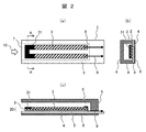
- FIG. It is (a) top view, (b) side view of AA cross section, and (c) front view of the corrosion environment monitoring apparatus 1 of Example 2.
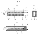
- FIG. 1 It is (a) top view, (b) side view of AA cross section, and (c) front view of the corrosion environment monitoring apparatus 1 of Example 3.
- FIG. It is (a) top view, (b) side view of AA cross section, and (c) front view of the corrosion environment monitoring apparatus 1 of Example 4.
- FIG. It is (a) top view, (b) side view of AA cross section, and (c) front view of the corrosion environment monitoring apparatus 1 of Example 5.
- FIG. 1 It is (a) top view, (b) side view of AA cross section, and (c) front view of the corrosion environment monitoring apparatus 1 of Example 7.
- the decrease in measurement accuracy at the initial stage of monitoring the corrosiveness of the environment is suppressed, and the corrosiveness of the environment is highly accurate over a long period of time even in an environment where the corrosiveness is extremely severe during the entire monitoring period.
- the corrosive environment monitoring device and method for continuous measurement will be described.
- a corrosive environment monitoring device and a method for measuring the degree of corrosion in the environment will be described in particular.
- FIG. 1 is (a) a top view, (b) a side view of an AA cross section, and (c) a front view of a conventional example corrosion environment monitoring device 1.
- the corrosion environment monitoring device 1 has the following configuration.
- a base metal thin film 2 made of an insulating plate 4, a material that is hard to corrode against a corrosive gas 10 existing in the environment and has a small resistance temperature change, and a base metal thin film 2 as a support member.
- a sensor chip 20 composed of a U-shaped sensing metal thin film 3 formed in the entire region above 2 and made of a material that is easily corroded by a corrosive gas 10.
- the substrate 5 on which the sensor chip 20 is formed (3) By encapsulating the substrate 5, having an opening 7 of the gas passage 8 in the side surface direction (one surface), and sealing the other surface other than the opening 7 surface on one surface, the inside is corrosive. Housing 6 forming the gas passage 8 of the gas 10.
- Drawer electrodes 9 formed at both ends of the sensor chip 20 to measure the electric resistance value.
- the U-shape is a short side portion formed with a predetermined width on the opening 7 side and both sides of the short side portion, from the opening 7 side to the depth side of the gas passage 8 ( It has two long side portions formed with a predetermined width toward FIG. 1A and the right side of FIG. 1C).
- the corrosive environment monitoring device 1 has an opening 7 on one surface, and by sealing the other surface other than the surface of the opening 7 on one surface, a gas passage 8 of the corrosive gas 10 is formed inside.
- the base metal is formed from the opening 7 side toward the depth side of the gas passage 8 and is not easily corroded by the corrosive gas 10, and the base metal thin film 2 is used as a support member for the base metal.
- FIG. 2 is (a) a top view, (b) a side view of an AA cross section, and (c) a front view after exposure of the conventional corrosive environment monitoring device 1.
- the corrosive gas 10 existing in the environment invades through the opening 7 and the concentration flux of the corrosive gas 10 is introduced.
- the corroded region (region where the corrosion product 31 is generated) of the sensing metal thin film 3 extends from the opening 7 having a high opening toward the depth side (right side) of the gas passage 8.
- the upper surface of the sensing metal thin film 3 (the surface in contact with the gas passage 8) is corroded faster than the lower surface of the sensing metal thin film 3.
- This corrosion behavior is realized by the gas passage 8 that limits the diffusion direction of the corrosive gas 10 and controls the corrosion rate of the sensing metal thin film 3.
- the metal (sensing metal) used for the sensing metal thin film 3 is a metal having a small specific resistance and a large specific resistance of the corrosion product 31 produced.
- the metal (base metal) used for the base metal thin film 2 is a metal having a higher specific resistance than the sensing metal.
- the amount of corrosion can be estimated from the measured electric resistance value by obtaining the relationship between the amount of corrosion of the sensing metal thin film 3 and the electric resistance value between the extraction electrodes 9 in advance. Further, by obtaining the relationship between the amount of corrosion of the sensing metal thin film 3 and the concentration of corrosive gas in the environment in advance, the corrosive gas concentration can be estimated from the measured electrical resistance value.
- FIG. 3 shows the corrosion status of the laminate composed of the insulating plate, the base metal thin film, and the sensing metal thin film at the time before exposure, the time after exposure A, the time B after exposure, and the time C after exposure in the conventional corrosion environment monitoring device 1. It is a front view which shows, and the graph which shows the relationship between the exposure time and the electric resistance value corresponding to the corrosion state.
- the corrosion status of the conventional corrosive environment monitoring device 1 at the time before exposure, the time after exposure A, the time B after exposure, and the time C after exposure (time after exposure A ⁇ time after exposure B ⁇ time after exposure C).
- the change in the electric resistance value between the extraction electrodes 9 formed at both ends of the sensor chip 20 corresponding to the above will be schematically described.
- the conventional corrosion monitoring device 1 shown in FIG. 1 is described by using the sensor chip 20, but here, for the sake of simplicity, an I-type (rectangular) sensor chip is used. And explain. Then, in FIG. 3, the opening 7 side of the I-type sensor chip is enlarged and shown. It is assumed that the electric resistance value is measured at both ends of the I-type sensor chip.
- the electrical resistivity value of the sensor chip before exposure is indicated by the electrical resistivity value (electrical resistance R SM1 ) of the sensing metal thin film 3 because the specific resistance of the sensing metal is smaller than the specific resistance of the base metal. ..
- the corrosive gas 10 existing in the environment forms a corrosive product 31 from the upper surface of the sensing metal thin film 3 in contact with the gas passage 8. Since the corrosive gas 10 penetrates from the opening 7 (left side) toward the depth side (right side) of the gas passage 8, the sensing metal thin film 3 has a high concentration flux of the corrosive gas 10. Corrodes from.
- the corrosion product 31 is partially formed at the left end of the sensing metal thin film 3, and only L of the sensing metal thin film 3 remains.
- the electrical resistance values of the sensor chip at the time A after exposure are the electrical resistance R BM2 and electrical resistance R BM3 of the base metal thin film 2, the electrical resistance R SM2 and electrical resistance R SM3 of the sensing metal thin film 3, and the electrical resistance of the corrosion product 31. It is shown by the equivalent circuit of R CP2.
- the electrical resistivity value of the sensor chip at the post-exposure time A is indicated by a dotted arrow based on the magnitude relationship between the specific resistance of the base metal, the specific resistance of the sensing metal, and the specific resistance of the corrosion product 31, and the sensing metal thin film. It can be approximated by a series circuit (direct resistance) of the electrical resistivity R SM2 of 3 and the electrical resistivity R SM3. The change between the electrical resistance value of the sensor chip at the time A after exposure and the electrical resistance value of the sensor chip before exposure is still small.
- the corrosive gas 10 existing in the environment forms a corrosive product 31 from the upper surface of the sensing metal thin film 3 in contact with the gas passage 8. Since the corrosive gas 10 further invades from the opening 7 (left side) toward the depth side of the gas passage 8, the sensing metal thin film 3 is formed from the opening 7 having a high concentration flux of the corrosive gas 10. Furthermore, it corrodes.
- the corrosion product 31 reaches the lower surface of the sensing metal thin film 3 at the left end of the sensing metal thin film 3, and the sensing metal thin film 3 does not remain.
- the electrical resistivity value of the sensor chip at the time B after exposure is indicated by a dotted arrow based on the magnitude relationship between the specific resistance of the base metal, the specific resistance of the sensing metal, and the specific resistance of the corrosion product 31, and the sensing metal thin film. It can be approximated by a series circuit (direct resistance) of the electrical resistivity R SM4 of 3 and the electrical resistivity R SM5. The change between the electrical resistance value of the sensor chip at time B after exposure and the electrical resistance value of the sensor chip before exposure is still small.
- the corrosive gas 10 existing in the environment forms a corrosive product 31 from the upper surface of the sensing metal thin film 3 in contact with the gas passage 8. Since the corrosive gas 10 penetrates further from the opening 7 (left side) toward the depth side of the gas passage 8, the sensing metal thin film 3 has a high concentration flux of the corrosive gas 10. From 7 onwards, it further corrodes.
- the corrosion product 31 At the post-exposure time C, at the left end of the sensing metal thin film 3, the corrosion product 31 reaches the lower surface of the sensing metal thin film 3, the sensing metal thin film 3 does not remain, and further, on the lower surface of the sensing metal thin film 3.
- the corrosion product 31 is formed toward the depth side of the gas passage 8.
- the electrical resistance values of the sensor chip at time C after exposure are the electrical resistance R BM6 and electrical resistance R BM7 and electrical resistance R BM8 of the base metal thin film 2, the electrical resistance R SM7 and electrical resistance R SM8 of the sensing metal thin film 3, and corrosion formation. It is shown by an equivalent circuit of the electrical resistance R CP6 and the air resistance R CP7 of the object 31.
- the electrical resistance value of the sensor chip at time C after exposure is indicated by a dotted arrow based on the magnitude relationship between the specific resistance of the base metal, the specific resistance of the sensing metal, and the specific resistance of the corrosion product 31, and the base metal thin film. It can be approximated by a series circuit (direct resistance) of the electric resistance R BM6 of 2 and the electric resistance R SM7 and the electric resistance R SM8 of the sensing metal thin film 3. The change between the electrical resistance value of the sensor chip at time C after exposure and the electrical resistance value of the sensor chip before exposure is large.
- FIG. 4 shows the corrosion status of the laminated body composed of the insulating plate, the base metal thin film, and the sensing metal thin film at each of the post-exposure time a, the post-exposure time b, and the post-exposure time c in the conventional example corrosion environment monitoring device 1. It is a top view, a front view, and a graph which shows the relationship between the exposure time and the electric resistance value corresponding to the corrosion state.
- the corrosion product 31 reaches the lower surface of the sensing metal thin film 3, the sensing metal thin film 3 does not remain, and further, on the lower surface of the sensing metal thin film 3.
- the corrosion product 31 is formed toward the depth side (right side) of the gas passage 8. That is, on the left side of the sensing metal thin film 3, a region where the sensing metal thin film 3 does not remain is recognized.
- the change in the electrical resistance value of the sensor chip 20 is small. Therefore, the measurement accuracy at the initial stage of monitoring the corrosiveness of the environment is lowered.
- the corrosion environment monitoring device 1 of the first embodiment will be described.
- the basic configuration of the conventional corrosive environment monitoring device 1 is also applied to the first embodiment.
- FIG. 5 is (a) a top view, (b) a side view of an AA cross section, and (c) a front view of the corrosion environment monitoring device 1 of the first embodiment.
- the corrosive environment monitoring device 1 of the first embodiment has the following configuration.
- a base metal thin film 2 made of a material that is difficult to change and has a small change in resistance temperature, and a material that is formed on the base metal thin film 2 with the base metal thin film 2 as a support member and is easily corroded by a corrosive gas 10.
- a sensor chip (laminate) 20 composed of a sensing metal thin film 3 (thickness of 1 ⁇ m or less) formed in a part of a region (two long side portions 3a and 3b) on the metal thin film 2 and a sensing metal thin film 3 (thickness is 1 ⁇ m or less).
- the substrate 5 on which the sensor chip 20 is formed (3) The sensor chip 20 is included, the opening 7 (width is 10 mm or less, height is 5 mm or less) is provided in the side surface direction (one surface), and the other surface other than the opening 7 surface on one surface is sealed.
- a housing 6 that forms a gas passage 8 of a corrosive gas 10 inside by stopping.
- Drawer electrodes 9 formed at both ends of the sensor chip 20 to measure the electric resistance value.
- the corrosive environment monitoring device 1 of the first embodiment has an opening 7 on one surface, and by sealing the other surface other than the surface of the opening 7 on one surface, the gas of the corrosive gas 10 is contained therein.
- It has a sensing metal thin film 3 which is an easy-to-use measuring member, and an extraction electrode 9 formed on both sides of the base metal thin film 2 to measure an electric resistance value.
- the base metal thin film 2 is on the insulating plate 4, and has a short side portion formed with a predetermined width on the opening 7 side.
- the sensing metal thin film 3 is formed on both sides of the short side portion and is formed on two long side portions having a predetermined width from the opening 7 side toward the depth side of the gas passage 8.
- the short side portion on the opening 7 side is a laminated portion composed of the insulating plate 4 and the base metal thin film 2, and the two long side portions (3a and 3b) are.
- the partial region on the base metal thin film 2 is two long side portions formed from the opening 7 side toward the depth side of the gas passage 10 except for the short side portion.
- the opening 7 side of the sensing metal thin film 3 has a shape parallel to the opening 7.
- the sensing metal is a metal having a small specific resistance and a large specific resistance of the produced corrosion product 31.
- metals such as copper, copper alloys, silver, silver alloys (for example, silver-palladium alloys, etc.), aluminum, iron, zinc, lead, etc., and metals having different electrical resistance values between the metals and their corrosion products 31. be.
- the base metal is a metal with a higher resistivity than the sensing metal.
- metals such as titanium, chromium, gold, palladium and stainless steel.
- the sensing metal for example, using silver
- corrosive gas 10 for example, H 2 S, in the case were such S 8
- the silver sulfide is generated.
- the corrosion environment monitoring method of Example 1 is to measure the degree of corrosion in the environment by using such a corrosion environment monitoring device 1, and by forming a part region on the sensing metal thin film 3. , Increase the elongation rate of the region where corrosion products are produced in some regions.
- Example 1 it is possible to suppress a decrease in measurement accuracy at the initial stage of monitoring the corrosiveness of the environment. Then, during the entire monitoring period, the corrosiveness of the environment can be continuously measured with high accuracy for a long period of time even in an environment where the corrosiveness is extremely severe.
- the base metal thin film 2 is formed by shifting from the opening 7 to the depth side of the gas passage 8, and the sensing metal thin film 2 is further formed from the opening 7 to the gas passage 8 than the base metal thin film 2. It is formed by shifting it to the depth side. This makes it possible to stabilize the measurement accuracy at the initial stage of monitoring the corrosiveness of the environment.
- the following steps are used.
- the base metal thin film 2 is formed on the insulating plate 4 by sputtering or plating.
- the region where the sensing metal thin film 2 is formed is formed (on both sides of the short side portion, formed with a predetermined width from the opening 7 side toward the depth side of the gas passage 8).
- masking is applied to form the sensing metal thin film 2 by sputtering or plating.
- the following steps are used.
- the base metal thin film 2 and the sensing metal thin film 3 are formed on the insulating plate 4 by sputtering or plating.
- the region where the sensing metal thin film 3 is formed is formed (on both sides of the short side portion, from the opening 7 side toward the depth side of the gas passage 8) is formed with a predetermined width. The two long sides) are masked, and the sensing metal thin film 3 is removed by etching. In the etching, a solution that is inactive on the base metal thin film 2 and active only on the sensing metal thin film 3 is used.
- sensing metal thin film 3 in a part of the base metal thin film 2
- screen printing or inkjet printer printing can also be used.
- the corrosive environment monitoring device 1 of the first embodiment can also be used as a highly reliable gas sensor for grasping a change in the corrosive gas concentration of the corrosive gas 10.
- the corrosion environment monitoring device 1 of the second embodiment will be described.
- the basic configuration of the conventional corrosive environment monitoring device 1 is also applied to the second embodiment.
- FIG. 6 is (a) a top view, (b) a side view of an AA cross section, and (c) a front view of the corrosion environment monitoring device 1 of the second embodiment.
- the corrosive environment monitoring device 1 of the second embodiment has a different tip shape on the opening 7 side of the sensing metal thin film 3 than the corrosive environment monitoring device 1 of the first embodiment.
- a region (constant cross-sectional area region) on the depth side of the gas passage 8 is located on the opening 7 side of the sensing metal thin film 3.
- the sensing metal thin film 3 has a narrow region (see FIG. 6A) as compared with the above. That is, in the sensing metal thin film 3 formed in a partial region on the base metal thin film 2, the width of the sensing metal thin film 3 is narrower on the opening 7 side than in the depth side region of the gas passage 8. A region (pointed portion: a region in which the width of the sensing metal thin film 3 continuously increases from the opening 7 side toward the depth side of the gas passage 8) is formed.
- the sharpened portion may be a region where the width of the sensing metal thin film 3 gradually increases.
- the sharpened portion is a region where the cross-sectional area increases from the opening 7 side toward the depth side of the gas passage 8, and the width of the sensing metal thin film 3 is directed from the opening 7 side toward the depth side of the gas passage 8. It is an area that grows continuously.
- the sharpened portion is a region whose cross-sectional area is smaller than that of the region on the depth side of the gas passage 8.
- the concentration flux of the corrosive gas 10 that has entered through the opening 7 is concentrated in the sharp portion where the width of the sensing metal thin film 3 is narrow, the sensing metal thin film 3 is corroded until the corrosion product 31 is generated.
- the time is shortened, and the sharpened portion has a faster extension rate of the region where the corrosion product 31 is produced than the sharpened portion on the depth side of the gas passage 8.
- Example 2 the time from before exposure to time B after exposure can be shortened, and a decrease in measurement accuracy at the initial stage of monitoring the corrosiveness of the environment can be suppressed.
- the corrosion environment monitoring device 1 of the third embodiment will be described.
- the basic configuration of the conventional corrosive environment monitoring device 1 is also applied to the third embodiment.
- FIG. 7 is (a) a top view, (b) a side view of an AA cross section, and (c) a front view of the corrosion environment monitoring device 1 of the third embodiment.
- the corrosive environment monitoring device 1 of the third embodiment has a different tip shape on the opening 7 side of the sensing metal thin film 3 than the corrosive environment monitoring device 1 of the first embodiment.
- a region (constant cross-sectional area region) on the depth side of the gas passage 8 is located on the opening 7 side of the sensing metal thin film 3.
- the sensing metal thin film 3 has a region where the film thickness is thin (see FIG. 7C). That is, the sensing metal thin film 3 formed in a partial region on the base metal thin film 2 has a film thickness of the sensing metal thin film 3 on the opening 7 side as compared with the region on the depth side of the gas passage 8.
- a thin region (sharp portion: a region in which the height of the sensing metal thin film 3 gradually increases from the opening 7 side toward the depth side of the gas passage 8) is formed.
- the region where the thickness of the sensing metal thin film 3 is thin is a region whose cross-sectional area is smaller than the region on the depth side of the gas passage 8.
- the concentration flux of the corrosive gas 10 that has entered through the opening 7 is concentrated in the region where the film thickness of the sensing metal thin film 3 is thin, the sensing metal thin film 3 is corroded until the corrosive product 31 is generated.
- the time is shortened, and in the region where the film thickness is thin, the elongation rate of the region where the corrosion product 31 is generated becomes faster than the region on the depth side of the gas passage 8 as compared with the region where the film thickness is thin.
- the sharp portion is a region where the height of the sensing metal thin film 3 is lower than the region on the depth side of the gas passage 8.
- This sharp portion may be a region where the height of the sensing metal thin film 3 gradually increases from the opening 7 side toward the depth side of the gas passage 8, and the height of the sensing metal thin film 3 may be increased. It may be a region that grows continuously.
- Example 3 the time from before exposure to time B after exposure can be shortened, and a decrease in measurement accuracy at the initial stage of monitoring the corrosiveness of the environment can be suppressed.
- the corrosion environment monitoring device 1 of the fourth embodiment will be described.
- the basic configuration of the conventional corrosive environment monitoring device 1 is also applied to the fourth embodiment.
- FIG. 8 is (a) a top view, (b) a side view of an AA cross section, and (c) a front view of the corrosion environment monitoring device 1 of the fourth embodiment.
- the corrosive environment monitoring device 1 of the fourth embodiment is different from the corrosive environment monitoring device 1 of the first embodiment in that the coating thin film 41 is formed on the opening 7 side of the sensing metal thin film 3.
- the coating thin film 41 is formed on the sensing metal thin film 3 on the opening 7 side of the sensing metal thin film 3. .. That is, in the fourth embodiment, the sensing metal thin film 3 has a region on which the coating thin film 41 is formed on the opening 7 side.
- the coating thin film 41 is made of a material that is not easily corroded by the corrosive gas 10 and has a small resistance temperature change, like the base metal thin film 2.
- the coating thin film 41 is not limited to a metal material, and may be an organic material as long as the corrosive gas 10 permeates the coating thin film 41 and does not corrode the sensing metal thin film 3 formed below the coating thin film 41. good.
- the concentration flux of the corrosive gas 10 that has entered through the opening 7 is concentrated on the side surface (tip) of the sensing metal thin film 3 on the opening 7 side, the sensing metal thin film 3 is corroded and the corrosion product 31
- the time until the coating thin film 41 is formed is shortened, and the corrosion product 31 is formed in the region where the coating thin film 41 is formed as compared with the region on the depth side of the gas passage 8 than the region where the coating thin film 41 is formed.
- the elongation rate of the generated region is increased.
- Example 4 the time from before exposure to time B after exposure can be shortened, and a decrease in measurement accuracy at the initial stage of monitoring the corrosiveness of the environment can be suppressed.
- Example 5 The basic configuration of the conventional corrosive environment monitoring device 1 is also applied to the fifth embodiment.
- FIG. 9 is (a) a top view, (b) a side view of an AA cross section, and (c) a front view of the corrosion environment monitoring device 1 of the fifth embodiment.
- the corrosive environment monitoring device 1 of the fifth embodiment has a different tip shape on the opening 7 side of the sensing metal thin film 3 than the corrosive environment monitoring device 1 of the first embodiment.
- a region (constant cross-sectional area region) on the depth side of the gas passage 8 is located on the opening 7 side of the sensing metal thin film 3.
- the sensing metal thin film 3 has a narrow region (see FIG. 9A) as compared with the above. That is, in the sensing metal thin film 3 formed in a partial region on the base metal thin film 2, the width of the sensing metal thin film 3 is narrower on the opening 7 side than in the depth side region of the gas passage 8. A region (pointed portion: a region in which the width of the sensing metal thin film 3 gradually increases from the opening 7 side toward the depth side of the gas passage 8) is formed.
- the sharpened portion may be a region where the width of the sensing metal thin film 3 continuously increases.
- the sharpened portion is a region where the cross-sectional area increases from the opening 7 side toward the depth side of the gas passage 8, and the width of the sensing metal thin film 3 is directed from the opening 7 side toward the depth side of the gas passage 8. This is an area that gradually grows.
- the sharpened portion is a region whose cross-sectional area is smaller than that of the region on the depth side of the gas passage 8.
- the concentration flux of the corrosive gas 10 that has entered through the opening 7 is concentrated in the sharp portion where the width of the sensing metal thin film 3 is narrow, the sensing metal thin film 3 is corroded until the corrosion product 31 is generated.
- the time is shortened, and the sharpened portion has a faster extension rate of the region where the corrosion product 31 is produced than the sharpened portion on the depth side of the gas passage 8.
- Example 5 the time from before exposure to time B after exposure can be shortened, and a decrease in measurement accuracy at the initial stage of monitoring the corrosiveness of the environment can be suppressed.
- the corrosion environment monitoring device 1 of the sixth embodiment will be described.
- the basic configuration of the conventional corrosive environment monitoring device 1 is also applied to the sixth embodiment.
- FIG. 10 is (a) a top view, (b) a side view of an AA cross section, and (c) a front view of the corrosion environment monitoring device 1 of the sixth embodiment.
- the corrosive environment monitoring device 1 of the sixth embodiment is different from the corrosive environment monitoring device 1 of the first embodiment in that it has the shape of the tip portion 42 on the opening 7 side of the sensing metal thin film 3.
- a region (constant cross-sectional area region) on the depth side of the gas passage 8 is located on the opening 7 side of the sensing metal thin film 3.
- the base metal thin film 2 and the sensing metal thin film 3 have a narrow region (see FIG. 10A). That is, the base metal thin film 2 and the sensing metal thin film 3 formed in a part of the insulating plate 4 have the base metal thin film 2 on the opening 7 side as compared with the deep side region of the gas passage 8. And a narrow region (tip portion 42) of the sensing metal thin film 3 is formed.
- the tip portion 42 is formed in a partial region on the insulating plate 4, and the base metal thin film 2 and the sensing metal thin film 3 on the opening 7 side are cut out and formed.
- the tip portion 42 can be formed by mechanically cutting in addition to sputtering by masking or etching by masking.
- the tip portion 42 is a region whose cross-sectional area is smaller than that of the region on the depth side of the gas passage 8.
- the tip portion 42 is a region in which the widths of the base metal thin film 2 and the sensing metal thin film 3 are continuously increased as compared with the region on the depth side of the gas passage 8.
- the concentration flux of the corrosive gas 10 invading from the opening 7 is concentrated on the tip portion 42, the time until the sensing metal thin film 3 corrodes and the corrosive product 31 is generated is shortened, and the tip portion In 42, the extension rate of the region where the corrosion product 31 is generated is faster than that of the region on the depth side of the gas passage 8 as compared with the tip portion 42.
- Example 6 the time from pre-exposure to post-exposure time B can be shortened, and due to the effect of the base metal having a large electrical resistance, the measurement accuracy at the initial stage of monitoring the corrosiveness of the environment is further improved. The decrease can be suppressed.
- Example 7 The basic configuration of the conventional corrosive environment monitoring device 1 is also applied to the seventh embodiment.
- FIG. 11 is (a) a top view, (b) a side view of an AA cross section, and (c) a front view of the corrosion environment monitoring device 1 of the seventh embodiment.
- the corrosive environment monitoring device 1 of the seventh embodiment is different from the corrosive environment monitoring device 1 of the first embodiment in that it has the shape of the tip portion 43 on the opening 7 side of the sensing metal thin film 3.
- a region (constant cross-sectional area region) on the depth side of the gas passage 8 is located on the opening 7 side of the sensing metal thin film 3.
- the base metal thin film 2 and the sensing metal thin film 3 have a narrow region (see FIG. 11A) as compared with the above. That is, the base metal thin film 2 and the sensing metal thin film 3 formed in a part of the insulating plate 4 have the base metal thin film 2 on the opening 7 side as compared with the deep side region of the gas passage 8. And a narrow region (tip portion 43) of the sensing metal thin film 3 is formed.
- the tip portion 43 is formed in a partial region on the insulating plate 4, and the base metal thin film 2 and the sensing metal thin film 3 on the opening 7 side are cut out and formed.
- the tip portion 43 can be formed by mechanically cutting in addition to sputtering by masking and etching by masking.
- the tip portion 43 is a region whose cross-sectional area is smaller than that of the region on the depth side of the gas passage 8.
- the tip portion 43 is a region in which the widths of the base metal thin film 2 and the sensing metal thin film 3 are gradually increased as compared with the region on the depth side of the gas passage 8.
- the concentration flux of the corrosive gas 10 that has entered through the opening 7 is concentrated on the tip portion 43, the time until the sensing metal thin film 3 corrodes and the corrosive product 31 is generated is shortened, and the tip portion In 43, the extension rate of the region where the corrosion product 31 is generated is faster than that in the region on the depth side of the gas passage 8 as compared with the tip portion 43.
- Example 7 the time from pre-exposure to post-exposure time B can be shortened, and due to the effect of the base metal having a large electrical resistance, the measurement accuracy at the initial stage of monitoring the corrosiveness of the environment is further improved. The decrease can be suppressed.
- Example 8 The basic configuration of the corrosive environment monitoring device 1 of the conventional example is also applied to the eighth embodiment.
- FIG. 12 is (a) a top view, (b) a side view of an AA cross section, and (c) a front view of the corrosion environment monitoring device 1 of the fourth embodiment.
- the corrosive environment monitoring device 1 of the eighth embodiment has a different open shape on the opening 7 side of the housing 6 than the corrosive environment monitoring device 1 of the first embodiment.
- the height (cross-sectional area) of the gas passage 8 formed in the region on the opening 7 side is the gas passage 8
- the height of the gas passage 8 is higher (larger cross-sectional area) than the height (cross-sectional area) of the gas passage 8 formed in the region on the depth side (constant cross-sectional area) (FIG. 12 (FIG. 12). c) has).
- the region 81 having a high height of the gas passage 8 is a region having a large cross-sectional area as compared with the region on the depth side of the gas passage 8.
- the region 81 having a high height of the gas passage 8 since the region 81 having a high height of the gas passage 8 is formed, the total amount of the corrosive gas 10 invading from the opening 7 increases, and the corrosive gas 10 is a sensing metal thin film on the opening 7 side. Focus on 3. Therefore, the sensing metal thin film 3 on the opening 7 side is corroded, and the corrosion product 31 is generated in the region 81 where the height of the gas passage 8 is high as compared with the region on the depth side of the gas passage 8. The extension rate of the region becomes faster.
- a region 81 having a high height of the gas passage 8 is formed, and the region 81 having a high height of the gas passage 8 has a height thereof from the opening 7 side toward the depth side of the gas passage 8.
- the area may be a region where the height is gradually reduced, or a region where the height may be continuously reduced.
- Example 8 the time from before exposure to time B after exposure can be shortened, and a decrease in measurement accuracy at the initial stage of monitoring the corrosiveness of the environment can be suppressed.
- the corrosion environment monitoring device 1 of the thirteenth embodiment will be described.
- the basic configuration of the conventional corrosive environment monitoring device 1 is also applied to the thirteenth embodiment.
- FIG. 13 is (a) a top view, (b) a side view of an AA cross section, and (c) a front view of the corrosion environment monitoring device 1 of the ninth embodiment.
- the corrosive environment monitoring device 1 of the ninth embodiment has a different open shape on the opening 7 side of the housing 6 than the corrosive environment monitoring device 1 of the first embodiment.
- the width (cross-sectional area) of the gas passage 8 formed in the region on the opening 7 side is different from that of the gas passage 8.
- a region 91 in which the width of the gas passage 8 is wider (larger in cross-sectional area) than the width (cross-sectional area) of the gas passage 8 formed in the region on the depth side (constant cross-sectional area).
- the wide region 91 of the gas passage 8 is a region having a large cross-sectional area as compared with the region on the depth side of the gas passage 8.
- the wide region 91 of the gas passage 8 since the wide region 91 of the gas passage 8 is formed, the total amount of the corrosive gas 10 invading from the opening 7 increases, and the corrosive gas 10 is the sensing metal thin film 3 on the opening 7 side. Focus on. Therefore, the sensing metal thin film 3 on the opening 7 side is corroded, and the wide region 91 of the gas passage 8 is a region where the corrosion product 31 is generated as compared with the region on the depth side of the gas passage 8. The elongation speed of is increased.
- the wide region 91 of the gas passage 8 is formed, and the width of the wide region 91 of the gas passage 8 is increased from the opening 7 side toward the depth side of the gas passage 8. It may be a region that becomes smaller gradually, or it may be a region that becomes smaller continuously.
- Example 5 the time from before exposure to time B after exposure can be shortened, and a decrease in measurement accuracy at the initial stage of monitoring the corrosiveness of the environment can be suppressed.
- the present invention is not limited to the above-described embodiment, and includes various modifications.
- the above-described embodiment has been specifically described in order to explain the present invention in an easy-to-understand manner, and is not necessarily limited to those having all the described configurations.
Landscapes
- Life Sciences & Earth Sciences (AREA)
- Analytical Chemistry (AREA)
- General Physics & Mathematics (AREA)
- Environmental & Geological Engineering (AREA)
- Environmental Sciences (AREA)
- Physics & Mathematics (AREA)
- Health & Medical Sciences (AREA)
- Ecology (AREA)
- Biochemistry (AREA)
- Chemical & Material Sciences (AREA)
- General Health & Medical Sciences (AREA)
- Biodiversity & Conservation Biology (AREA)
- Immunology (AREA)
- Pathology (AREA)
- Testing Resistance To Weather, Investigating Materials By Mechanical Methods (AREA)
- Investigating Or Analyzing Materials By The Use Of Electric Means (AREA)
Priority Applications (2)
| Application Number | Priority Date | Filing Date | Title |
|---|---|---|---|
| US17/918,142 US12181402B2 (en) | 2020-04-22 | 2021-02-16 | Corrosive environment monitoring device and corrosive environment monitoring method |
| CN202180030212.2A CN115427784B (zh) | 2020-04-22 | 2021-02-16 | 腐蚀环境监测装置和方法 |
Applications Claiming Priority (2)
| Application Number | Priority Date | Filing Date | Title |
|---|---|---|---|
| JP2020075851A JP7401387B2 (ja) | 2020-04-22 | 2020-04-22 | 腐食環境モニタリング装置 |
| JP2020-075851 | 2020-04-22 |
Publications (1)
| Publication Number | Publication Date |
|---|---|
| WO2021215091A1 true WO2021215091A1 (ja) | 2021-10-28 |
Family
ID=78270542
Family Applications (1)
| Application Number | Title | Priority Date | Filing Date |
|---|---|---|---|
| PCT/JP2021/005682 Ceased WO2021215091A1 (ja) | 2020-04-22 | 2021-02-16 | 腐食環境モニタリング装置及び方法 |
Country Status (4)
| Country | Link |
|---|---|
| US (1) | US12181402B2 (https=) |
| JP (1) | JP7401387B2 (https=) |
| CN (1) | CN115427784B (https=) |
| WO (1) | WO2021215091A1 (https=) |
Families Citing this family (4)
| Publication number | Priority date | Publication date | Assignee | Title |
|---|---|---|---|---|
| CN114660159B (zh) * | 2022-03-21 | 2024-04-05 | 中国石油化工股份有限公司 | 一种减缓醋酸乙烯装置精馏系统腐蚀的方法 |
| US20240085310A1 (en) * | 2022-09-12 | 2024-03-14 | Antony Trueman | Resistance-Based Sensor System for Measuring Atmospheric Corrosion |
| EP4545939A1 (en) | 2023-10-25 | 2025-04-30 | ABB Schweiz AG | An atmospheric corrosion sensor |
| EP4545940A1 (en) | 2023-10-25 | 2025-04-30 | ABB Schweiz AG | An atmospheric corrosion sensor |
Citations (2)
| Publication number | Priority date | Publication date | Assignee | Title |
|---|---|---|---|---|
| JP2003294606A (ja) * | 2002-04-02 | 2003-10-15 | Masahiro Kitada | 環境評価方式およびそれを用いた環境評価装置 |
| WO2017061182A1 (ja) * | 2015-10-07 | 2017-04-13 | 株式会社日立製作所 | 腐食環境モニタリング装置及び方法 |
Family Cites Families (7)
| Publication number | Priority date | Publication date | Assignee | Title |
|---|---|---|---|---|
| BE783143A (fr) * | 1972-05-05 | 1972-09-01 | Centre Rech Metallurgique | Dispositif pour essais de corrosion atmospherique. |
| US20070165215A1 (en) * | 2006-01-17 | 2007-07-19 | Honeywell International Inc. | Contactless corrosion sensor |
| JP5798955B2 (ja) * | 2012-03-13 | 2015-10-21 | 株式会社日立製作所 | 腐食環境モニタリング装置 |
| JP6362920B2 (ja) * | 2014-05-16 | 2018-07-25 | 株式会社日立製作所 | 腐食環境モニタリング装置及び方法 |
| EP3441745B1 (en) * | 2016-04-08 | 2021-04-07 | Hitachi, Ltd. | Corrosive environment monitoring device |
| JP6893168B2 (ja) * | 2017-12-25 | 2021-06-23 | 株式会社日立製作所 | 腐食環境モニタリング装置及び腐食診断装置 |
| US11754490B2 (en) * | 2019-09-05 | 2023-09-12 | Dell Products L.P. | System and method for sensing corrosion in an enclosure of an information handling system |
-
2020
- 2020-04-22 JP JP2020075851A patent/JP7401387B2/ja active Active
-
2021
- 2021-02-16 CN CN202180030212.2A patent/CN115427784B/zh active Active
- 2021-02-16 US US17/918,142 patent/US12181402B2/en active Active
- 2021-02-16 WO PCT/JP2021/005682 patent/WO2021215091A1/ja not_active Ceased
Patent Citations (2)
| Publication number | Priority date | Publication date | Assignee | Title |
|---|---|---|---|---|
| JP2003294606A (ja) * | 2002-04-02 | 2003-10-15 | Masahiro Kitada | 環境評価方式およびそれを用いた環境評価装置 |
| WO2017061182A1 (ja) * | 2015-10-07 | 2017-04-13 | 株式会社日立製作所 | 腐食環境モニタリング装置及び方法 |
Also Published As
| Publication number | Publication date |
|---|---|
| US12181402B2 (en) | 2024-12-31 |
| CN115427784A (zh) | 2022-12-02 |
| US20230134944A1 (en) | 2023-05-04 |
| JP7401387B2 (ja) | 2023-12-19 |
| CN115427784B (zh) | 2024-12-24 |
| JP2021173568A (ja) | 2021-11-01 |
Similar Documents
| Publication | Publication Date | Title |
|---|---|---|
| WO2021215091A1 (ja) | 腐食環境モニタリング装置及び方法 | |
| US9291543B1 (en) | PC board mount corrosion sensitive sensor | |
| CN108139342B (zh) | 腐蚀环境监测装置及方法 | |
| CN105092456B (zh) | 用于监控腐蚀环境的装置以及方法 | |
| JP6084935B2 (ja) | 腐食センサおよびその製造方法 | |
| KR102274158B1 (ko) | 부식 감시 장치 | |
| JP2005026378A (ja) | 半導体キャリア用フィルムおよびそれを用いた半導体装置、液晶モジュール | |
| Lee et al. | Effect of bias voltage on the electrochemical migration behaviors of Sn and Pb | |
| Noh et al. | Behaviour of electrochemical migration with solder alloys on printed circuit boards (PCBs) | |
| Jia et al. | Dynamic characteristics and mechanism of ions migration and dendrites evolution on the printed circuit board surface | |
| US20110266681A1 (en) | Electronic component as well as method for its production | |
| Dominkovics et al. | Effects of flux residues on surface insulation resistance and electrochemical migration | |
| KR102058648B1 (ko) | 박막 트랜지스터의 제조 방법 및 박막 트랜지스터 | |
| Wang et al. | Study of the Effect of Bias Voltage on the Electrochemical Migration Failure of Surface-Mount Resistor | |
| Wagner et al. | A critical review of corrosion phenomena in microelectronic systems | |
| JP2010129730A (ja) | 配線基板及びこれを用いたプローブカード | |
| JPS6117126A (ja) | 液晶セル | |
| JP4550080B2 (ja) | 半導体装置および液晶モジュール | |
| JP5863866B2 (ja) | 半導体キャリア用フィルムのマイグレーション抑制方法 | |
| JP5788342B2 (ja) | 半導体キャリア用フィルムおよびそれを用いた半導体装置、液晶モジュール | |
| JP4850887B2 (ja) | 半導体装置の使用方法 | |
| JP5394649B2 (ja) | 半導体キャリア用フィルムおよびそれを用いた半導体装置、液晶モジュール | |
| JP2017015565A (ja) | 腐食センサ | |
| Kersey et al. | Gold dendrite simulation: Root cause determination | |
| Seng | Reliability of microelectronic packages with tin-plated copper leads under high humidity operating environment |
Legal Events
| Date | Code | Title | Description |
|---|---|---|---|
| 121 | Ep: the epo has been informed by wipo that ep was designated in this application |
Ref document number: 21793408 Country of ref document: EP Kind code of ref document: A1 |
|
| NENP | Non-entry into the national phase |
Ref country code: DE |
|
| 122 | Ep: pct application non-entry in european phase |
Ref document number: 21793408 Country of ref document: EP Kind code of ref document: A1 |