WO2021214832A1 - 冷凍サイクル装置 - Google Patents
冷凍サイクル装置 Download PDFInfo
- Publication number
- WO2021214832A1 WO2021214832A1 PCT/JP2020/017058 JP2020017058W WO2021214832A1 WO 2021214832 A1 WO2021214832 A1 WO 2021214832A1 JP 2020017058 W JP2020017058 W JP 2020017058W WO 2021214832 A1 WO2021214832 A1 WO 2021214832A1
- Authority
- WO
- WIPO (PCT)
- Prior art keywords
- heat exchange
- exchange section
- refrigerant
- section
- region
- Prior art date
Links
Images


Classifications
-
- F—MECHANICAL ENGINEERING; LIGHTING; HEATING; WEAPONS; BLASTING
- F28—HEAT EXCHANGE IN GENERAL
- F28D—HEAT-EXCHANGE APPARATUS, NOT PROVIDED FOR IN ANOTHER SUBCLASS, IN WHICH THE HEAT-EXCHANGE MEDIA DO NOT COME INTO DIRECT CONTACT
- F28D1/00—Heat-exchange apparatus having stationary conduit assemblies for one heat-exchange medium only, the media being in contact with different sides of the conduit wall, in which the other heat-exchange medium is a large body of fluid, e.g. domestic or motor car radiators
- F28D1/02—Heat-exchange apparatus having stationary conduit assemblies for one heat-exchange medium only, the media being in contact with different sides of the conduit wall, in which the other heat-exchange medium is a large body of fluid, e.g. domestic or motor car radiators with heat-exchange conduits immersed in the body of fluid
- F28D1/04—Heat-exchange apparatus having stationary conduit assemblies for one heat-exchange medium only, the media being in contact with different sides of the conduit wall, in which the other heat-exchange medium is a large body of fluid, e.g. domestic or motor car radiators with heat-exchange conduits immersed in the body of fluid with tubular conduits
- F28D1/047—Heat-exchange apparatus having stationary conduit assemblies for one heat-exchange medium only, the media being in contact with different sides of the conduit wall, in which the other heat-exchange medium is a large body of fluid, e.g. domestic or motor car radiators with heat-exchange conduits immersed in the body of fluid with tubular conduits the conduits being bent, e.g. in a serpentine or zig-zag
- F28D1/0477—Heat-exchange apparatus having stationary conduit assemblies for one heat-exchange medium only, the media being in contact with different sides of the conduit wall, in which the other heat-exchange medium is a large body of fluid, e.g. domestic or motor car radiators with heat-exchange conduits immersed in the body of fluid with tubular conduits the conduits being bent, e.g. in a serpentine or zig-zag the conduits being bent in a serpentine or zig-zag
-
- F—MECHANICAL ENGINEERING; LIGHTING; HEATING; WEAPONS; BLASTING
- F25—REFRIGERATION OR COOLING; COMBINED HEATING AND REFRIGERATION SYSTEMS; HEAT PUMP SYSTEMS; MANUFACTURE OR STORAGE OF ICE; LIQUEFACTION SOLIDIFICATION OF GASES
- F25B—REFRIGERATION MACHINES, PLANTS OR SYSTEMS; COMBINED HEATING AND REFRIGERATION SYSTEMS; HEAT PUMP SYSTEMS
- F25B41/00—Fluid-circulation arrangements
- F25B41/20—Disposition of valves, e.g. of on-off valves or flow control valves
-
- F—MECHANICAL ENGINEERING; LIGHTING; HEATING; WEAPONS; BLASTING
- F24—HEATING; RANGES; VENTILATING
- F24F—AIR-CONDITIONING; AIR-HUMIDIFICATION; VENTILATION; USE OF AIR CURRENTS FOR SCREENING
- F24F1/00—Room units for air-conditioning, e.g. separate or self-contained units or units receiving primary air from a central station
- F24F1/06—Separate outdoor units, e.g. outdoor unit to be linked to a separate room comprising a compressor and a heat exchanger
- F24F1/38—Fan details of outdoor units, e.g. bell-mouth shaped inlets or fan mountings
-
- F—MECHANICAL ENGINEERING; LIGHTING; HEATING; WEAPONS; BLASTING
- F25—REFRIGERATION OR COOLING; COMBINED HEATING AND REFRIGERATION SYSTEMS; HEAT PUMP SYSTEMS; MANUFACTURE OR STORAGE OF ICE; LIQUEFACTION SOLIDIFICATION OF GASES
- F25B—REFRIGERATION MACHINES, PLANTS OR SYSTEMS; COMBINED HEATING AND REFRIGERATION SYSTEMS; HEAT PUMP SYSTEMS
- F25B39/00—Evaporators; Condensers
- F25B39/02—Evaporators
-
- F—MECHANICAL ENGINEERING; LIGHTING; HEATING; WEAPONS; BLASTING
- F25—REFRIGERATION OR COOLING; COMBINED HEATING AND REFRIGERATION SYSTEMS; HEAT PUMP SYSTEMS; MANUFACTURE OR STORAGE OF ICE; LIQUEFACTION SOLIDIFICATION OF GASES
- F25B—REFRIGERATION MACHINES, PLANTS OR SYSTEMS; COMBINED HEATING AND REFRIGERATION SYSTEMS; HEAT PUMP SYSTEMS
- F25B39/00—Evaporators; Condensers
- F25B39/04—Condensers
-
- F—MECHANICAL ENGINEERING; LIGHTING; HEATING; WEAPONS; BLASTING
- F25—REFRIGERATION OR COOLING; COMBINED HEATING AND REFRIGERATION SYSTEMS; HEAT PUMP SYSTEMS; MANUFACTURE OR STORAGE OF ICE; LIQUEFACTION SOLIDIFICATION OF GASES
- F25B—REFRIGERATION MACHINES, PLANTS OR SYSTEMS; COMBINED HEATING AND REFRIGERATION SYSTEMS; HEAT PUMP SYSTEMS
- F25B40/00—Subcoolers, desuperheaters or superheaters
- F25B40/02—Subcoolers
-
- F—MECHANICAL ENGINEERING; LIGHTING; HEATING; WEAPONS; BLASTING
- F28—HEAT EXCHANGE IN GENERAL
- F28D—HEAT-EXCHANGE APPARATUS, NOT PROVIDED FOR IN ANOTHER SUBCLASS, IN WHICH THE HEAT-EXCHANGE MEDIA DO NOT COME INTO DIRECT CONTACT
- F28D1/00—Heat-exchange apparatus having stationary conduit assemblies for one heat-exchange medium only, the media being in contact with different sides of the conduit wall, in which the other heat-exchange medium is a large body of fluid, e.g. domestic or motor car radiators
- F28D1/02—Heat-exchange apparatus having stationary conduit assemblies for one heat-exchange medium only, the media being in contact with different sides of the conduit wall, in which the other heat-exchange medium is a large body of fluid, e.g. domestic or motor car radiators with heat-exchange conduits immersed in the body of fluid
- F28D1/04—Heat-exchange apparatus having stationary conduit assemblies for one heat-exchange medium only, the media being in contact with different sides of the conduit wall, in which the other heat-exchange medium is a large body of fluid, e.g. domestic or motor car radiators with heat-exchange conduits immersed in the body of fluid with tubular conduits
- F28D1/0408—Multi-circuit heat exchangers, e.g. integrating different heat exchange sections in the same unit or heat exchangers for more than two fluids
- F28D1/0417—Multi-circuit heat exchangers, e.g. integrating different heat exchange sections in the same unit or heat exchangers for more than two fluids with particular circuits for the same heat exchange medium, e.g. with the heat exchange medium flowing through sections having different heat exchange capacities or for heating/cooling the heat exchange medium at different temperatures
-
- F—MECHANICAL ENGINEERING; LIGHTING; HEATING; WEAPONS; BLASTING
- F28—HEAT EXCHANGE IN GENERAL
- F28D—HEAT-EXCHANGE APPARATUS, NOT PROVIDED FOR IN ANOTHER SUBCLASS, IN WHICH THE HEAT-EXCHANGE MEDIA DO NOT COME INTO DIRECT CONTACT
- F28D1/00—Heat-exchange apparatus having stationary conduit assemblies for one heat-exchange medium only, the media being in contact with different sides of the conduit wall, in which the other heat-exchange medium is a large body of fluid, e.g. domestic or motor car radiators
- F28D1/02—Heat-exchange apparatus having stationary conduit assemblies for one heat-exchange medium only, the media being in contact with different sides of the conduit wall, in which the other heat-exchange medium is a large body of fluid, e.g. domestic or motor car radiators with heat-exchange conduits immersed in the body of fluid
- F28D1/04—Heat-exchange apparatus having stationary conduit assemblies for one heat-exchange medium only, the media being in contact with different sides of the conduit wall, in which the other heat-exchange medium is a large body of fluid, e.g. domestic or motor car radiators with heat-exchange conduits immersed in the body of fluid with tubular conduits
- F28D1/0408—Multi-circuit heat exchangers, e.g. integrating different heat exchange sections in the same unit or heat exchangers for more than two fluids
- F28D1/0426—Multi-circuit heat exchangers, e.g. integrating different heat exchange sections in the same unit or heat exchangers for more than two fluids with units having particular arrangement relative to the large body of fluid, e.g. with interleaved units or with adjacent heat exchange units in common air flow or with units extending at an angle to each other or with units arranged around a central element
- F28D1/0435—Combination of units extending one behind the other
-
- F—MECHANICAL ENGINEERING; LIGHTING; HEATING; WEAPONS; BLASTING
- F28—HEAT EXCHANGE IN GENERAL
- F28D—HEAT-EXCHANGE APPARATUS, NOT PROVIDED FOR IN ANOTHER SUBCLASS, IN WHICH THE HEAT-EXCHANGE MEDIA DO NOT COME INTO DIRECT CONTACT
- F28D1/00—Heat-exchange apparatus having stationary conduit assemblies for one heat-exchange medium only, the media being in contact with different sides of the conduit wall, in which the other heat-exchange medium is a large body of fluid, e.g. domestic or motor car radiators
- F28D1/02—Heat-exchange apparatus having stationary conduit assemblies for one heat-exchange medium only, the media being in contact with different sides of the conduit wall, in which the other heat-exchange medium is a large body of fluid, e.g. domestic or motor car radiators with heat-exchange conduits immersed in the body of fluid
- F28D1/04—Heat-exchange apparatus having stationary conduit assemblies for one heat-exchange medium only, the media being in contact with different sides of the conduit wall, in which the other heat-exchange medium is a large body of fluid, e.g. domestic or motor car radiators with heat-exchange conduits immersed in the body of fluid with tubular conduits
- F28D1/0408—Multi-circuit heat exchangers, e.g. integrating different heat exchange sections in the same unit or heat exchangers for more than two fluids
- F28D1/0426—Multi-circuit heat exchangers, e.g. integrating different heat exchange sections in the same unit or heat exchangers for more than two fluids with units having particular arrangement relative to the large body of fluid, e.g. with interleaved units or with adjacent heat exchange units in common air flow or with units extending at an angle to each other or with units arranged around a central element
- F28D1/0452—Combination of units extending one behind the other with units extending one beside or one above the other
-
- F—MECHANICAL ENGINEERING; LIGHTING; HEATING; WEAPONS; BLASTING
- F28—HEAT EXCHANGE IN GENERAL
- F28F—DETAILS OF HEAT-EXCHANGE AND HEAT-TRANSFER APPARATUS, OF GENERAL APPLICATION
- F28F1/00—Tubular elements; Assemblies of tubular elements
- F28F1/10—Tubular elements and assemblies thereof with means for increasing heat-transfer area, e.g. with fins, with projections, with recesses
- F28F1/12—Tubular elements and assemblies thereof with means for increasing heat-transfer area, e.g. with fins, with projections, with recesses the means being only outside the tubular element
- F28F1/24—Tubular elements and assemblies thereof with means for increasing heat-transfer area, e.g. with fins, with projections, with recesses the means being only outside the tubular element and extending transversely
- F28F1/32—Tubular elements and assemblies thereof with means for increasing heat-transfer area, e.g. with fins, with projections, with recesses the means being only outside the tubular element and extending transversely the means having portions engaging further tubular elements
- F28F1/325—Fins with openings
-
- F—MECHANICAL ENGINEERING; LIGHTING; HEATING; WEAPONS; BLASTING
- F24—HEATING; RANGES; VENTILATING
- F24F—AIR-CONDITIONING; AIR-HUMIDIFICATION; VENTILATION; USE OF AIR CURRENTS FOR SCREENING
- F24F1/00—Room units for air-conditioning, e.g. separate or self-contained units or units receiving primary air from a central station
- F24F1/06—Separate outdoor units, e.g. outdoor unit to be linked to a separate room comprising a compressor and a heat exchanger
- F24F1/14—Heat exchangers specially adapted for separate outdoor units
-
- F—MECHANICAL ENGINEERING; LIGHTING; HEATING; WEAPONS; BLASTING
- F25—REFRIGERATION OR COOLING; COMBINED HEATING AND REFRIGERATION SYSTEMS; HEAT PUMP SYSTEMS; MANUFACTURE OR STORAGE OF ICE; LIQUEFACTION SOLIDIFICATION OF GASES
- F25B—REFRIGERATION MACHINES, PLANTS OR SYSTEMS; COMBINED HEATING AND REFRIGERATION SYSTEMS; HEAT PUMP SYSTEMS
- F25B13/00—Compression machines, plants or systems, with reversible cycle
-
- F—MECHANICAL ENGINEERING; LIGHTING; HEATING; WEAPONS; BLASTING
- F28—HEAT EXCHANGE IN GENERAL
- F28D—HEAT-EXCHANGE APPARATUS, NOT PROVIDED FOR IN ANOTHER SUBCLASS, IN WHICH THE HEAT-EXCHANGE MEDIA DO NOT COME INTO DIRECT CONTACT
- F28D21/00—Heat-exchange apparatus not covered by any of the groups F28D1/00 - F28D20/00
- F28D2021/0019—Other heat exchangers for particular applications; Heat exchange systems not otherwise provided for
- F28D2021/0068—Other heat exchangers for particular applications; Heat exchange systems not otherwise provided for for refrigerant cycles
Definitions
- the compressor 1, the four-way valve 2, the outdoor heat exchanger 3, the pressure reducing valve 4, the control device CD, and the blower device 6 are housed in the outdoor unit 101.
- the indoor heat exchanger 5 and the blower 7 are housed in the indoor unit 102.
- the refrigerant circulates in the order of the compressor 1, the four-way valve 2, the outdoor heat exchanger (condenser) 3, the pressure reducing valve 4, the indoor heat exchanger (evaporator) 5, and the four-way valve 2 during the cooling operation. It is configured as follows. Further, in the refrigerant circuit RC, during the heating operation, the refrigerant is supplied in the order of the compressor 1, the four-way valve 2, the indoor heat exchanger (condenser) 5, the pressure reducing valve 4, the outdoor heat exchanger (evaporator) 3, and the four-way valve 2. It is configured to circulate.
- the refrigerant is a non-azeotropic mixed refrigerant having a temperature gradient in which the temperature of the refrigerant decreases as the dryness of the refrigerant decreases.
- the refrigerant include R407C and R454A.
- the control device CD is configured to control each device of the refrigeration cycle device 100 by performing calculations, instructions, and the like.
- the control device CD is electrically connected to a compressor 1, a four-way valve 2, a pressure reducing valve 4, a blower device 6, 7, and the like, and is configured to control the operation of these.
- the compressor 1 is configured to compress the refrigerant.
- the compressor 1 is configured to compress and discharge the sucked refrigerant.
- the compressor 1 may be configured to have a variable capacity.
- the compressor 1 may be configured so that the capacity is changed by adjusting the rotation speed of the compressor 1 based on an instruction from the control device CD.
- the four-way valve 2 is configured to switch the flow of the refrigerant so that the refrigerant compressed by the compressor 1 flows to the outdoor heat exchanger 3 or the indoor heat exchanger 5.
- the four-way valve 2 is configured to allow the refrigerant discharged from the compressor 1 to flow to the outdoor heat exchanger (condenser) 3 during the cooling operation. Further, the four-way valve 2 is configured to allow the refrigerant discharged from the compressor 1 to flow to the indoor heat exchanger (evaporator) 5 during the heating operation.
- the outdoor heat exchanger 3 is configured to exchange heat between the refrigerant flowing inside the outdoor heat exchanger 3 and the air flowing outside the outdoor heat exchanger 3.
- the outdoor heat exchanger 3 is configured to function as a condenser that condenses the refrigerant during the cooling operation and as an evaporator that evaporates the refrigerant during the heating operation.
- the outdoor heat exchanger 3 is a fin-and-tube heat exchanger having a plurality of fins and a heat transfer tube penetrating the plurality of fins.
- the pressure reducing valve 4 is configured to reduce the pressure by expanding the refrigerant condensed by the condenser.
- the pressure reducing valve 4 is configured to reduce the pressure of the refrigerant condensed by the outdoor heat exchanger (condenser) 3 during the cooling operation and to reduce the pressure of the refrigerant condensed by the indoor heat exchanger (evaporator) 5 during the heating operation.
- the pressure reducing valve 4 is, for example, a solenoid valve.
- the indoor heat exchanger 5 is configured to exchange heat between the refrigerant flowing inside the indoor heat exchanger 5 and the air flowing outside the indoor heat exchanger 5.
- the indoor heat exchanger 5 is configured to function as an evaporator that evaporates the refrigerant during the cooling operation and as a condenser that condenses the refrigerant during the heating operation.
- the indoor heat exchanger 5 is a fin-and-tube heat exchanger having a plurality of fins and a heat transfer tube penetrating the plurality of fins.
- the blower 6 is configured to blow outdoor air to the outdoor heat exchanger 3. That is, the blower 6 is configured to supply air to the outdoor heat exchanger 3.
- the blower device 6 exchanges heat between the refrigerant and the air by adjusting the amount of air flowing around the outdoor heat exchanger 3 by adjusting the rotation speed of the blower device 6 based on the instruction from the control device CD. It may be configured to adjust the amount.
- the blower 7 is configured to blow indoor air to the indoor heat exchanger 5. That is, the blower 7 is configured to supply air to the indoor heat exchanger 5.
- the blower 7 exchanges heat between the refrigerant and the air by adjusting the amount of air flowing around the indoor heat exchanger 5 by adjusting the rotation speed of the blower 7 based on the instruction from the control device CD. It may be configured to adjust the amount.
- the solid line arrow in FIG. 1 indicates the flow of the refrigerant during the cooling operation
- the broken line arrow in FIG. 1 indicates the flow of the refrigerant during the heating operation.
- the refrigeration cycle device 100 can selectively perform a cooling operation and a heating operation.
- the refrigerant circulates in the refrigerant circuit RC in the order of the compressor 1, the four-way valve 2, the outdoor heat exchanger 3, the pressure reducing valve 4, the indoor heat exchanger 5, and the four-way valve 2.
- the outdoor heat exchanger 3 functions as a condenser. Heat exchange is performed between the refrigerant flowing through the outdoor heat exchanger 3 and the air blown by the blower device 6.
- the indoor heat exchanger 5 functions as an evaporator. Heat exchange is performed between the refrigerant flowing through the indoor heat exchanger 5 and the air blown by the blower device 7.
- the refrigerant circulates in the refrigerant circuit RC in the order of the compressor 1, the four-way valve 2, the indoor heat exchanger 5, the pressure reducing valve 4, the outdoor heat exchanger 3, and the four-way valve 2.
- the indoor heat exchanger 5 functions as a condenser. Heat exchange is performed between the refrigerant flowing through the indoor heat exchanger 5 and the air blown by the blower device 7.
- the outdoor heat exchanger 3 functions as an evaporator. Heat exchange is performed between the refrigerant flowing through the outdoor heat exchanger 3 and the air blown by the blower device 6.
- the indoor heat exchanger 5 may function as a condenser or an evaporator like the outdoor heat exchanger 3 and may have the same configuration as the outdoor heat exchanger 3.
- at least one of the outdoor heat exchanger 3 and the indoor heat exchanger 5 functioning as a condenser or an evaporator may have the following configuration.
- the first direction D1 may be orthogonal to the second direction D2.
- the first direction D1 may be the horizontal direction.
- the second direction D2 may be in the vertical direction (vertical direction).
- the third direction D3 is a direction in which the heat transfer portion P1 extends linearly.
- the third direction D3 may be orthogonal to the first direction D1 and the second direction D2.
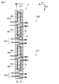
- the plurality of heat transfer units P1 are arranged in a plurality of stages in the second direction D2 in each of the first heat exchange unit C1 and the second heat exchange unit C2.
- the plurality of heat transfer portions P1 are arranged in four stages. That is, the plurality of heat transfer portions P1 are arranged in the first stage S1 to the fourth stage S4.
- each inflow path IF of the first heat exchange section C1 and the second heat exchange section C2 is a heat transfer section P1 arranged in the first stage S1.
- Each outflow path OF of the first heat exchange section C1 and the second heat exchange section C2 is a heat transfer section P1 arranged in the fourth stage S4.
- the refrigerant flows into the second heat exchange section C2 from the inflow path IF which is the heat transfer section P1 of the first stage S1 of the second heat exchange section C2.
- the refrigerant flows from the inflow path IF, which is the heat transfer section P1 of the first stage S1, to the outflow path OF, which is the heat transfer section P1 of the fourth stage S4, in the second heat exchange section C2.
- the refrigerant flows from the outflow path OF of the second heat exchange section C2 to the inflow path IF of the first heat exchange section C1.
- the refrigerant flows into the first heat exchange section C1 from the inflow path IF which is the heat transfer section P1 of the first stage S1 of the first heat exchange section C1.
- the refrigerant flows from the inflow path IF, which is the heat transfer section P1 of the first stage S1, to the outflow path OF, which is the heat transfer section P1 of the fourth stage S4, in the first heat exchange section C1. After that, the refrigerant flows out from the first heat exchange section C1.
- the refrigerant flows through the first heat exchange section C1 and the second heat exchange section C2 in an inverted N shape.
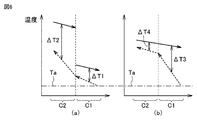
- the refrigerant flows from the second heat exchange section C2 toward the first heat exchange section C1. Air flows from the first heat exchange section C1 to the second heat exchange section C2. Therefore, the flow of the refrigerant flowing through the second heat exchange section C2 and the first heat exchange section C1 is countercurrent to the flow of air flowing through the first heat exchange section C1 and the second heat exchange section C2.
- FIG. 4A shows the temperatures of the refrigerant and air in the heat transfer section P1 of the first stage S1 of each of the first heat exchange section and the second heat exchange section.
- FIG. 4B shows the temperatures of the refrigerant and air in the heat transfer section P1 of the fourth stage S4 of each of the first heat exchange section and the second heat exchange section.
- the refrigerant flows into the second heat exchange section C2 from the inflow path IF which is the heat transfer section P1 of the first stage S1 of the second heat exchange section C2.
- the refrigerant flows from the inflow path IF, which is the heat transfer section P1 of the first stage S1, to the outflow path OF, which is the heat transfer section P1 of the fourth stage S4, in the second heat exchange section C2.
- the refrigerant flows into the first heat exchange section C1 from the inflow path IF which is the heat transfer section P1 of the fourth stage of the first heat exchange section C1.
- the refrigerant flows from the inflow path IF, which is the heat transfer section P1 of the fourth stage S4, to the outflow path OF, which is the heat transfer section P1 of the first stage S1, in the first heat exchange section C1.
- the refrigerant flows in a U shape through the first heat exchange section C1 and the second heat exchange section C2.
- the refrigerant is a non-azeotropic mixed refrigerant. Therefore, according to the refrigeration cycle apparatus 100 according to the first embodiment, it is possible to suppress a decrease in the amount of heat exchange while using a non-azeotropic mixed refrigerant having a low global warming potential.
- the outdoor heat exchanger 3 has two paths for flowing the refrigerant. That is, the outdoor heat exchanger 3 has a first pass PA and a second pass PB.
- the outdoor heat exchanger 3 may have two or more paths.
- Each of the first heat exchange region HF1 and the second heat exchange region HF2 has an inflow path IF and an outflow path OF of the first heat exchange section C1 and the second heat exchange section C2, respectively.
- the outflow path OF of the second heat exchange section C2 is arranged in the same stage as the outflow path OF of the first heat exchange section C1 in the second direction D2. Has been done.
- Each of the first heat exchange region HF1 and the second heat exchange region HF2 has a first heat exchange unit C1 and a second heat exchange unit C2.
- the plurality of heat transfer portions P1 are arranged in the first stage S1 to the fourth stage S4.
- each inflow path IF of the first heat exchange unit C1 and the second heat exchange unit C2 is the heat transfer unit P1 arranged in the first stage S1.
- Each outflow path OF of the first heat exchange section C1 and the second heat exchange section C2 is a heat transfer section P1 arranged in the fourth stage S4.
- each inflow path IF of the first heat exchange section C1 and the second heat exchange section C2 is the heat transfer section P1 arranged in the fourth stage S4.
- Each outflow path OF of the first heat exchange section C1 and the second heat exchange section C2 is a heat transfer section P1 arranged in the first stage S1.
- the plurality of heat transfer sections P1 are connected by the connecting section P2 as follows.
- the heat transfer portion P1 of the fourth stage S4 is connected to the heat transfer portion P1 of the third stage S3 on the back side by the connection portion P2.
- the heat transfer portion P1 of the third stage S3 is connected to the heat transfer portion P1 of the second stage S2 by the connection portion P2 on the front side.
- the heat transfer portion P1 of the second stage S2 is connected to the heat transfer portion P1 of the first stage S1 on the back side by the connection portion P2.
- the heat transfer unit P1 of the fourth stage S4 of the first heat exchange unit C1 is connected to the heat transfer unit P1 of the first stage S1 of the second heat exchange unit C2 by the connection unit P2 on the front side.
- the inflow passage IFs of the first heat exchange portions C1 of the first heat exchange region HF1 and the second heat exchange region HF2 are adjacent to each other in the second direction D2. Have been placed.
- the inflow passage IFs of the first heat exchange portions C1 of the first heat exchange region HF1 and the second heat exchange region HF2 are arranged in stages adjacent to each other.
- the refrigerant flows into the second heat exchange section C2 from the inflow path IF which is the heat transfer section P1 of the first stage S1 of the second heat exchange section C2.
- the refrigerant flows from the inflow path IF, which is the heat transfer section P1 of the first stage S1, to the outflow path OF, which is the heat transfer section P1 of the fourth stage S4, in the second heat exchange section C2.
- the refrigerant flows from the outflow path OF of the second heat exchange section C2 to the inflow path IF of the first heat exchange section C1.
- the refrigerant flows into the first heat exchange section C1 from the inflow path IF which is the heat transfer section P1 of the first stage S1 of the first heat exchange section C1.
- the refrigerant flows from the inflow path IF, which is the heat transfer section P1 of the first stage S1, to the outflow path OF, which is the heat transfer section P1 of the fourth stage S4, in the first heat exchange section C1. After that, the refrigerant flows out from the first heat exchange section C1.
- the refrigerant flows through the first heat exchange section C1 and the second heat exchange section C2 in an inverted N shape.
- the refrigerant flows into the second heat exchange section C2 from the inflow path IF which is the heat transfer section P1 of the fourth stage S4 of the second heat exchange section C2.
- the refrigerant flows from the inflow path IF, which is the heat transfer section P1 of the fourth stage S4, to the outflow path OF, which is the heat transfer section P1 of the first stage S1, in the second heat exchange section C2.
- the refrigerant flows from the outflow path OF of the second heat exchange section C2 to the inflow path IF of the first heat exchange section C1.
- the refrigerant flows into the first heat exchange section C1 from the inflow path IF which is the heat transfer section P1 of the fourth stage S4 of the first heat exchange section C1.
- the refrigerant flows from the inflow path IF, which is the heat transfer section P1 of the fourth stage S4, to the outflow path OF, which is the heat transfer section P1 of the first stage S1, in the first heat exchange section C1. After that, the refrigerant flows out from the first heat exchange section C1.
- the refrigerant flows through the first heat exchange section C1 and the second heat exchange section C2 in an N shape.
- the refrigerant flows from the second heat exchange unit C2 toward the first heat exchange unit C1. Air flows from the first heat exchange section C1 to the second heat exchange section C2. Therefore, the flow of the refrigerant flowing through the second heat exchange section C2 and the first heat exchange section C1 is countercurrent to the flow of air flowing through the first heat exchange section C1 and the second heat exchange section C2.
- the inflow paths IF of the above are arranged so as to be adjacent to each other in the second direction D2. Therefore, the temperature difference of the refrigerant flowing through the inflow path IF of each of the first heat exchange portions C1 of the first heat exchange region HF1 and the second heat exchange region HF2 can be reduced. Therefore, the heat loss between the first pass PA and the second pass PB can be reduced.
- the number of stages of the first heat exchange region HF1 and the second heat exchange region HF2 are different from each other. Further, in each of the first heat exchange region HF1 and the second heat exchange region HF2, the number of stages of the first heat exchange unit C1 and the second heat exchange unit C2 is different.
- the first pass PA and the second pass PB are not arranged line-symmetrically with each other in the second direction D2.
- the inflow path IF of the second heat exchange unit C2 is the heat transfer unit P1 arranged in the first stage S1.
- the outflow path OF of the second heat exchange section C2 is the heat transfer section P1 arranged in the seventh stage S7.
- the inflow path IF of the first heat exchange section C1 is the heat transfer section P1 arranged in the third stage S3.
- the outflow path OF of the first heat exchange section C1 is the heat transfer section P1 arranged in the seventh stage S7.
- the plurality of heat transfer portions P1 are arranged in the first stage S1 to the fifth stage S5.
- the inflow path IF of the second heat exchange section C2 is the heat transfer section P1 arranged in the third stage S3.
- the outflow path OF of the second heat exchange section C2 is the heat transfer section P1 arranged in the first stage S1.
- the inflow path IF of the first heat exchange section C1 is the heat transfer section P1 arranged in the fifth stage S5.
- the outflow path OF of the first heat exchange unit C1 is the heat transfer unit P1 arranged in the first stage S1.
- the inflow path IF of the second heat exchange unit C2 in the second direction D2. Is arranged in a stage different from the inflow path IF of the first heat exchange section C1. Therefore, the degree of freedom in design can be improved.
- the inflow path IF has an inner diameter larger than that of the outflow path OF.
- the temperature of the refrigerant in the inflow path IF is higher than the temperature of the refrigerant in the outflow path OF. Therefore, in the inflow path IF, the temperature difference between the refrigerant and the air is large, so that the amount of heat exchange is large.
- the blower 6 has a fan 6a having a tip and a root, a boss 6b to which the root of the fan 6a is fixed, and a motor 6c to which the boss 6b is rotatably connected.
- the blower 6 is, for example, a propeller fan.
- the outflow passages OF of the first heat exchange section C1 and the second heat exchange section C2 in the first heat exchange region HF1 are arranged so as to overlap the tip of the fan 6a in the first direction D1. That is, each outflow path OF of the first heat exchange section C1 and the second heat exchange section C2 in the first heat exchange region F1 is arranged so as to overlap the tip of the fan 6a when viewed from the first direction D1.
- the outflow passages OF of the first heat exchange section C1 and the second heat exchange section C2 in the second heat exchange region HF2 are arranged so as to overlap the boss 6b and the motor 6c in the first direction D1.
- the inflow paths IF of the first heat exchange section C1 and the second heat exchange section C2 in each of the first heat exchange region HF1 and the second heat exchange region HF2 are formed between the tip and the root of the fan 6a in the first direction D1. It is arranged so as to overlap the center.
- the center of the fan 6a is a portion that sandwiches the middle between the tip and the root of the fan 6a and is 40% or more and 60% or less of the distance between the tip and the root of the fan 6a in the first direction D1.
- the inflow paths IF of the first heat exchange section C1 and the second heat exchange section C2 in each of the first heat exchange region HF1 and the second heat exchange region HF2 are , It is arranged so as to overlap the center of the tip and the root of the fan 6a in the first direction D1. Therefore, the inflow passage IFs of the first heat exchange section C1 and the second heat exchange section C2 can be arranged so as to overlap the center of the fan 6a having a large wind speed (air volume). Therefore, the blowing temperature can be lowered.
- the outdoor heat exchanger 3 further has a subcool line SCL connected to the outflow path OF of the first heat exchange section C1 in each of the first heat exchange region HF1 and the second heat exchange region HF2. ing.
- the subcool line SCL is configured to cool the refrigerant into a supercooled state.
- the subcool line SCL is arranged so as to be adjacent to the outflow path OF of the first heat exchange section C1 in the first heat exchange region HF1 in the second direction D2.
- the subcool line SCL is arranged so as to be adjacent to the outflow path OF of the first heat exchange section C1 in the first heat exchange region HF1 in the second direction D2. Has been done. Therefore, the temperature difference of the refrigerant between the outflow path OF of the first heat exchange section C1 and the subcool line SCL in the first heat exchange region HF1 becomes small. Therefore, the heat loss between the first pass PA and the subcool line SCL can be reduced. Therefore, it is possible to suppress a decrease in the amount of heat exchange in the subcool line SCL.
- 1 Compressor 2 4-way valve, 3 outdoor heat exchanger, 4 pressure reducing valve, 5 indoor heat exchanger, 6, 7 blower, 6a fan, 6b boss, 6c motor, 100 refrigeration cycle device, 101 outdoor unit, 102 indoor Machine, C1 1st heat exchange unit, C2 2nd heat exchange unit, CD control device, D1 1st direction, D2 2nd direction, D3 3rd direction, F fin, HF1 1st heat exchange area, HF2 2nd heat exchange Area, IF inflow path, OF outflow path, P heat transfer tube, P1 heat transfer section, P2 connection section, PA 1st pass, PB 2nd pass, RC refrigerant circuit, SCL subcool line.
Landscapes
- Engineering & Computer Science (AREA)
- Mechanical Engineering (AREA)
- General Engineering & Computer Science (AREA)
- Physics & Mathematics (AREA)
- Thermal Sciences (AREA)
- Chemical & Material Sciences (AREA)
- Combustion & Propulsion (AREA)
- Geometry (AREA)
- Heat-Exchange Devices With Radiators And Conduit Assemblies (AREA)
- Other Air-Conditioning Systems (AREA)
Priority Applications (4)
| Application Number | Priority Date | Filing Date | Title |
|---|---|---|---|
| PCT/JP2020/017058 WO2021214832A1 (ja) | 2020-04-20 | 2020-04-20 | 冷凍サイクル装置 |
| US17/918,189 US20230126980A1 (en) | 2020-04-20 | 2020-04-20 | Refrigeration Cycle Apparatus |
| JP2022516487A JPWO2021214832A1 (de) | 2020-04-20 | 2020-04-20 | |
| EP20932319.5A EP4141348A4 (de) | 2020-04-20 | 2020-04-20 | Kältekreislaufvorrichtung |
Applications Claiming Priority (1)
| Application Number | Priority Date | Filing Date | Title |
|---|---|---|---|
| PCT/JP2020/017058 WO2021214832A1 (ja) | 2020-04-20 | 2020-04-20 | 冷凍サイクル装置 |
Publications (1)
| Publication Number | Publication Date |
|---|---|
| WO2021214832A1 true WO2021214832A1 (ja) | 2021-10-28 |
Family
ID=78270390
Family Applications (1)
| Application Number | Title | Priority Date | Filing Date |
|---|---|---|---|
| PCT/JP2020/017058 WO2021214832A1 (ja) | 2020-04-20 | 2020-04-20 | 冷凍サイクル装置 |
Country Status (4)
| Country | Link |
|---|---|
| US (1) | US20230126980A1 (de) |
| EP (1) | EP4141348A4 (de) |
| JP (1) | JPWO2021214832A1 (de) |
| WO (1) | WO2021214832A1 (de) |
Citations (12)
| Publication number | Priority date | Publication date | Assignee | Title |
|---|---|---|---|---|
| JPS432682Y1 (de) * | 1964-12-28 | 1968-02-03 | ||
| JPS54157308A (en) * | 1978-06-02 | 1979-12-12 | Hitachi Ltd | Outdoor unit of separate type air conditioner |
| JPS6380465U (de) * | 1986-11-14 | 1988-05-27 | ||
| JPH06272998A (ja) * | 1993-03-18 | 1994-09-27 | Toshiba Corp | 冷凍装置 |
| JPH06307738A (ja) * | 1993-04-21 | 1994-11-01 | Hitachi Ltd | 非共沸混合冷媒用凝縮器 |
| JPH07269985A (ja) | 1994-03-31 | 1995-10-20 | Toshiba Corp | 熱交換器 |
| JPH07280375A (ja) * | 1994-04-06 | 1995-10-27 | Hitachi Ltd | 空気調和装置 |
| JPH10281574A (ja) * | 1997-04-07 | 1998-10-23 | Hitachi Ltd | 空気調和機 |
| JP2001066017A (ja) * | 1999-08-27 | 2001-03-16 | Hitachi Ltd | 空気調和機 |
| JP2013113493A (ja) * | 2011-11-29 | 2013-06-10 | Panasonic Corp | 熱交換素子とそれを用いた熱交換換気機器 |
| JP2014206054A (ja) * | 2013-04-10 | 2014-10-30 | 日立アプライアンス株式会社 | 空気調和装置 |
| JP2016114263A (ja) * | 2014-12-12 | 2016-06-23 | ジョンソンコントロールズ ヒタチ エア コンディショニング テクノロジー(ホンコン)リミテッド | 空気調和機 |
Family Cites Families (5)
| Publication number | Priority date | Publication date | Assignee | Title |
|---|---|---|---|---|
| JP2008111622A (ja) * | 2006-10-31 | 2008-05-15 | Toshiba Kyaria Kk | 熱交換器、これを用いた空気調和機の室外機 |
| JP5956743B2 (ja) * | 2011-11-29 | 2016-07-27 | 日立アプライアンス株式会社 | 空気調和機 |
| KR20140105431A (ko) * | 2011-12-06 | 2014-09-01 | 파나소닉 주식회사 | 공기 조화기 및 냉동 사이클 장치 |
| JP5644889B2 (ja) * | 2013-04-30 | 2014-12-24 | ダイキン工業株式会社 | 空気調和機の室内ユニット |
| JP6681991B2 (ja) * | 2016-08-09 | 2020-04-15 | 三菱電機株式会社 | 熱交換器及びこの熱交換器を備えた冷凍サイクル装置 |
-
2020
- 2020-04-20 JP JP2022516487A patent/JPWO2021214832A1/ja active Pending
- 2020-04-20 EP EP20932319.5A patent/EP4141348A4/de active Pending
- 2020-04-20 WO PCT/JP2020/017058 patent/WO2021214832A1/ja unknown
- 2020-04-20 US US17/918,189 patent/US20230126980A1/en active Pending
Patent Citations (12)
| Publication number | Priority date | Publication date | Assignee | Title |
|---|---|---|---|---|
| JPS432682Y1 (de) * | 1964-12-28 | 1968-02-03 | ||
| JPS54157308A (en) * | 1978-06-02 | 1979-12-12 | Hitachi Ltd | Outdoor unit of separate type air conditioner |
| JPS6380465U (de) * | 1986-11-14 | 1988-05-27 | ||
| JPH06272998A (ja) * | 1993-03-18 | 1994-09-27 | Toshiba Corp | 冷凍装置 |
| JPH06307738A (ja) * | 1993-04-21 | 1994-11-01 | Hitachi Ltd | 非共沸混合冷媒用凝縮器 |
| JPH07269985A (ja) | 1994-03-31 | 1995-10-20 | Toshiba Corp | 熱交換器 |
| JPH07280375A (ja) * | 1994-04-06 | 1995-10-27 | Hitachi Ltd | 空気調和装置 |
| JPH10281574A (ja) * | 1997-04-07 | 1998-10-23 | Hitachi Ltd | 空気調和機 |
| JP2001066017A (ja) * | 1999-08-27 | 2001-03-16 | Hitachi Ltd | 空気調和機 |
| JP2013113493A (ja) * | 2011-11-29 | 2013-06-10 | Panasonic Corp | 熱交換素子とそれを用いた熱交換換気機器 |
| JP2014206054A (ja) * | 2013-04-10 | 2014-10-30 | 日立アプライアンス株式会社 | 空気調和装置 |
| JP2016114263A (ja) * | 2014-12-12 | 2016-06-23 | ジョンソンコントロールズ ヒタチ エア コンディショニング テクノロジー(ホンコン)リミテッド | 空気調和機 |
Non-Patent Citations (1)
| Title |
|---|
| See also references of EP4141348A4 |
Also Published As
| Publication number | Publication date |
|---|---|
| EP4141348A4 (de) | 2023-08-09 |
| JPWO2021214832A1 (de) | 2021-10-28 |
| US20230126980A1 (en) | 2023-04-27 |
| EP4141348A1 (de) | 2023-03-01 |
Similar Documents
| Publication | Publication Date | Title |
|---|---|---|
| US10386081B2 (en) | Air-conditioning device | |
| WO2019239446A1 (ja) | 空気調和装置の室外機及び空気調和装置 | |
| WO2013160957A1 (ja) | 熱交換器、室内機及び冷凍サイクル装置 | |
| JP5195733B2 (ja) | 熱交換器及びこれを備えた冷凍サイクル装置 | |
| TW201825838A (zh) | 除濕裝置 | |
| WO2021065913A1 (ja) | 蒸発器、およびそれを備えた冷凍サイクル装置 | |
| JP2019215161A (ja) | 空気調和装置の室外機及び空気調和装置 | |
| WO2021214832A1 (ja) | 冷凍サイクル装置 | |
| JP7414845B2 (ja) | 冷凍サイクル装置 | |
| JP7123238B2 (ja) | 冷凍サイクル装置 | |
| WO2021245877A1 (ja) | 熱交換器および冷凍サイクル装置 | |
| WO2019155571A1 (ja) | 熱交換器および冷凍サイクル装置 | |
| JP4983878B2 (ja) | 熱交換器及びこの熱交換器を備えた冷蔵庫、空気調和機 | |
| WO2023188421A1 (ja) | 室外機およびそれを備えた空気調和装置 | |
| JP2008121995A (ja) | 空気調和機 | |
| TWI810896B (zh) | 除濕裝置 | |
| JP7229255B2 (ja) | 室外機、及び、冷凍サイクル装置 | |
| WO2023281655A1 (ja) | 熱交換器および冷凍サイクル装置 | |
| WO2024203167A1 (ja) | 熱交換器及び熱交換器を備えた冷凍サイクル装置 | |
| JP7050538B2 (ja) | 熱交換器および空気調和機 | |
| WO2023281656A1 (ja) | 熱交換器および冷凍サイクル装置 | |
| WO2022157979A1 (ja) | 室外機、空気調和機および室外機の設計方法 | |
| WO2023175926A1 (ja) | 空気調和装置の室外機および空気調和装置 | |
| JP3749193B2 (ja) | 空気調和装置 | |
| WO2021255780A1 (ja) | 空気調和装置の室外機 |
Legal Events
| Date | Code | Title | Description |
|---|---|---|---|
| 121 | Ep: the epo has been informed by wipo that ep was designated in this application |
Ref document number: 20932319 Country of ref document: EP Kind code of ref document: A1 |
|
| ENP | Entry into the national phase |
Ref document number: 2022516487 Country of ref document: JP Kind code of ref document: A |
|
| NENP | Non-entry into the national phase |
Ref country code: DE |
|
| ENP | Entry into the national phase |
Ref document number: 2020932319 Country of ref document: EP Effective date: 20221121 |