WO2021210618A1 - 放射線画像処理方法、学習済みモデル、放射線画像処理モジュール、放射線画像処理プログラム、及び放射線画像処理システム - Google Patents
放射線画像処理方法、学習済みモデル、放射線画像処理モジュール、放射線画像処理プログラム、及び放射線画像処理システム Download PDFInfo
- Publication number
- WO2021210618A1 WO2021210618A1 PCT/JP2021/015489 JP2021015489W WO2021210618A1 WO 2021210618 A1 WO2021210618 A1 WO 2021210618A1 JP 2021015489 W JP2021015489 W JP 2021015489W WO 2021210618 A1 WO2021210618 A1 WO 2021210618A1
- Authority
- WO
- WIPO (PCT)
- Prior art keywords
- image
- radiation
- image processing
- trained model
- jig
- Prior art date
- Legal status (The legal status is an assumption and is not a legal conclusion. Google has not performed a legal analysis and makes no representation as to the accuracy of the status listed.)
- Ceased
Links
Images







Classifications
-
- G—PHYSICS
- G01—MEASURING; TESTING
- G01N—INVESTIGATING OR ANALYSING MATERIALS BY DETERMINING THEIR CHEMICAL OR PHYSICAL PROPERTIES
- G01N23/00—Investigating or analysing materials by the use of wave or particle radiation, e.g. X-rays or neutrons, not covered by groups G01N3/00 – G01N17/00, G01N21/00 or G01N22/00
- G01N23/02—Investigating or analysing materials by the use of wave or particle radiation, e.g. X-rays or neutrons, not covered by groups G01N3/00 – G01N17/00, G01N21/00 or G01N22/00 by transmitting the radiation through the material
- G01N23/04—Investigating or analysing materials by the use of wave or particle radiation, e.g. X-rays or neutrons, not covered by groups G01N3/00 – G01N17/00, G01N21/00 or G01N22/00 by transmitting the radiation through the material and forming images of the material
-
- G—PHYSICS
- G01—MEASURING; TESTING
- G01N—INVESTIGATING OR ANALYSING MATERIALS BY DETERMINING THEIR CHEMICAL OR PHYSICAL PROPERTIES
- G01N23/00—Investigating or analysing materials by the use of wave or particle radiation, e.g. X-rays or neutrons, not covered by groups G01N3/00 – G01N17/00, G01N21/00 or G01N22/00
- G01N23/02—Investigating or analysing materials by the use of wave or particle radiation, e.g. X-rays or neutrons, not covered by groups G01N3/00 – G01N17/00, G01N21/00 or G01N22/00 by transmitting the radiation through the material
- G01N23/06—Investigating or analysing materials by the use of wave or particle radiation, e.g. X-rays or neutrons, not covered by groups G01N3/00 – G01N17/00, G01N21/00 or G01N22/00 by transmitting the radiation through the material and measuring the absorption
- G01N23/083—Investigating or analysing materials by the use of wave or particle radiation, e.g. X-rays or neutrons, not covered by groups G01N3/00 – G01N17/00, G01N21/00 or G01N22/00 by transmitting the radiation through the material and measuring the absorption the radiation being X-rays
-
- G—PHYSICS
- G01—MEASURING; TESTING
- G01N—INVESTIGATING OR ANALYSING MATERIALS BY DETERMINING THEIR CHEMICAL OR PHYSICAL PROPERTIES
- G01N23/00—Investigating or analysing materials by the use of wave or particle radiation, e.g. X-rays or neutrons, not covered by groups G01N3/00 – G01N17/00, G01N21/00 or G01N22/00
- G01N23/02—Investigating or analysing materials by the use of wave or particle radiation, e.g. X-rays or neutrons, not covered by groups G01N3/00 – G01N17/00, G01N21/00 or G01N22/00 by transmitting the radiation through the material
- G01N23/06—Investigating or analysing materials by the use of wave or particle radiation, e.g. X-rays or neutrons, not covered by groups G01N3/00 – G01N17/00, G01N21/00 or G01N22/00 by transmitting the radiation through the material and measuring the absorption
- G01N23/083—Investigating or analysing materials by the use of wave or particle radiation, e.g. X-rays or neutrons, not covered by groups G01N3/00 – G01N17/00, G01N21/00 or G01N22/00 by transmitting the radiation through the material and measuring the absorption the radiation being X-rays
- G01N23/087—Investigating or analysing materials by the use of wave or particle radiation, e.g. X-rays or neutrons, not covered by groups G01N3/00 – G01N17/00, G01N21/00 or G01N22/00 by transmitting the radiation through the material and measuring the absorption the radiation being X-rays using polyenergetic X-rays
-
- G—PHYSICS
- G01—MEASURING; TESTING
- G01T—MEASUREMENT OF NUCLEAR OR X-RADIATION
- G01T1/00—Measuring X-radiation, gamma radiation, corpuscular radiation, or cosmic radiation
- G01T1/16—Measuring radiation intensity
- G01T1/20—Measuring radiation intensity with scintillation detectors
- G01T1/208—Circuits specially adapted for scintillation detectors, e.g. for the photo-multiplier section
-
- G—PHYSICS
- G06—COMPUTING OR CALCULATING; COUNTING
- G06N—COMPUTING ARRANGEMENTS BASED ON SPECIFIC COMPUTATIONAL MODELS
- G06N20/00—Machine learning
-
- G—PHYSICS
- G06—COMPUTING OR CALCULATING; COUNTING
- G06N—COMPUTING ARRANGEMENTS BASED ON SPECIFIC COMPUTATIONAL MODELS
- G06N3/00—Computing arrangements based on biological models
- G06N3/02—Neural networks
- G06N3/08—Learning methods
-
- G—PHYSICS
- G06—COMPUTING OR CALCULATING; COUNTING
- G06T—IMAGE DATA PROCESSING OR GENERATION, IN GENERAL
- G06T5/00—Image enhancement or restoration
- G06T5/60—Image enhancement or restoration using machine learning, e.g. neural networks
-
- G—PHYSICS
- G06—COMPUTING OR CALCULATING; COUNTING
- G06T—IMAGE DATA PROCESSING OR GENERATION, IN GENERAL
- G06T5/00—Image enhancement or restoration
- G06T5/70—Denoising; Smoothing
-
- G—PHYSICS
- G06—COMPUTING OR CALCULATING; COUNTING
- G06T—IMAGE DATA PROCESSING OR GENERATION, IN GENERAL
- G06T7/00—Image analysis
- G06T7/0002—Inspection of images, e.g. flaw detection
- G06T7/0004—Industrial image inspection
-
- G—PHYSICS
- G01—MEASURING; TESTING
- G01N—INVESTIGATING OR ANALYSING MATERIALS BY DETERMINING THEIR CHEMICAL OR PHYSICAL PROPERTIES
- G01N2223/00—Investigating materials by wave or particle radiation
- G01N2223/03—Investigating materials by wave or particle radiation by transmission
- G01N2223/04—Investigating materials by wave or particle radiation by transmission and measuring absorption
-
- G—PHYSICS
- G01—MEASURING; TESTING
- G01N—INVESTIGATING OR ANALYSING MATERIALS BY DETERMINING THEIR CHEMICAL OR PHYSICAL PROPERTIES
- G01N2223/00—Investigating materials by wave or particle radiation
- G01N2223/10—Different kinds of radiation or particles
- G01N2223/101—Different kinds of radiation or particles electromagnetic radiation
- G01N2223/1016—X-ray
-
- G—PHYSICS
- G01—MEASURING; TESTING
- G01N—INVESTIGATING OR ANALYSING MATERIALS BY DETERMINING THEIR CHEMICAL OR PHYSICAL PROPERTIES
- G01N2223/00—Investigating materials by wave or particle radiation
- G01N2223/40—Imaging
- G01N2223/401—Imaging image processing
-
- G—PHYSICS
- G01—MEASURING; TESTING
- G01N—INVESTIGATING OR ANALYSING MATERIALS BY DETERMINING THEIR CHEMICAL OR PHYSICAL PROPERTIES
- G01N2223/00—Investigating materials by wave or particle radiation
- G01N2223/50—Detectors
- G01N2223/501—Detectors array
- G01N2223/5015—Detectors array linear array
-
- G—PHYSICS
- G01—MEASURING; TESTING
- G01N—INVESTIGATING OR ANALYSING MATERIALS BY DETERMINING THEIR CHEMICAL OR PHYSICAL PROPERTIES
- G01N2223/00—Investigating materials by wave or particle radiation
- G01N2223/50—Detectors
- G01N2223/505—Detectors scintillation
-
- G—PHYSICS
- G06—COMPUTING OR CALCULATING; COUNTING
- G06T—IMAGE DATA PROCESSING OR GENERATION, IN GENERAL
- G06T2207/00—Indexing scheme for image analysis or image enhancement
- G06T2207/10—Image acquisition modality
- G06T2207/10004—Still image; Photographic image
-
- G—PHYSICS
- G06—COMPUTING OR CALCULATING; COUNTING
- G06T—IMAGE DATA PROCESSING OR GENERATION, IN GENERAL
- G06T2207/00—Indexing scheme for image analysis or image enhancement
- G06T2207/10—Image acquisition modality
- G06T2207/10116—X-ray image
-
- G—PHYSICS
- G06—COMPUTING OR CALCULATING; COUNTING
- G06T—IMAGE DATA PROCESSING OR GENERATION, IN GENERAL
- G06T2207/00—Indexing scheme for image analysis or image enhancement
- G06T2207/10—Image acquisition modality
- G06T2207/10116—X-ray image
- G06T2207/10121—Fluoroscopy
-
- G—PHYSICS
- G06—COMPUTING OR CALCULATING; COUNTING
- G06T—IMAGE DATA PROCESSING OR GENERATION, IN GENERAL
- G06T2207/00—Indexing scheme for image analysis or image enhancement
- G06T2207/20—Special algorithmic details
- G06T2207/20081—Training; Learning
-
- G—PHYSICS
- G06—COMPUTING OR CALCULATING; COUNTING
- G06T—IMAGE DATA PROCESSING OR GENERATION, IN GENERAL
- G06T2207/00—Indexing scheme for image analysis or image enhancement
- G06T2207/20—Special algorithmic details
- G06T2207/20084—Artificial neural networks [ANN]
-
- G—PHYSICS
- G06—COMPUTING OR CALCULATING; COUNTING
- G06T—IMAGE DATA PROCESSING OR GENERATION, IN GENERAL
- G06T2207/00—Indexing scheme for image analysis or image enhancement
- G06T2207/20—Special algorithmic details
- G06T2207/20172—Image enhancement details
- G06T2207/20182—Noise reduction or smoothing in the temporal domain; Spatio-temporal filtering
-
- G—PHYSICS
- G06—COMPUTING OR CALCULATING; COUNTING
- G06T—IMAGE DATA PROCESSING OR GENERATION, IN GENERAL
- G06T2207/00—Indexing scheme for image analysis or image enhancement
- G06T2207/30—Subject of image; Context of image processing
- G06T2207/30108—Industrial image inspection
- G06T2207/30128—Food products
Definitions
- One aspect of the embodiment relates to a radiation image processing method, a trained model, a radiation image processing module, a radiation image processing program, and a radiation image processing system.
- noise removal may not be sufficient when a radiation image generated by transmitting radiation such as X-rays through an object is targeted.
- the relationship between the brightness and noise in an image tends to fluctuate depending on the conditions of a radiation source such as an X-ray source, the type of filter used, and the like, and the noise tends to be unable to be effectively removed.
- one aspect of the embodiment is made in view of such a problem, and is a radiation image processing method, a trained model, a radiation image processing module, a radiation image processing program, and a radiation image processing program capable of effectively removing noise in a radiation image.
- An object of the present invention is to provide a radiographic image processing system.
- a radiation image of a jig is acquired by using a system that irradiates an object with radiation, images the radiation transmitted through the object, and acquires a radiation image.
- the trained model according to another aspect of the embodiment is a trained model used in the above-mentioned radiation image processing method, which is constructed by machine learning using image data and is transmitted to a processor from a radiation image of an object. Perform image processing to remove noise.
- the radiation image processing module uses a system that irradiates the object with radiation, images the radiation transmitted through the object, and acquires a radiation image, and uses a jig and the object.
- a plurality of trained models constructed by machine learning in advance using image data based on the image characteristics, the acquisition unit that acquires the radiation image of the device, and the specific unit that specifies the image characteristics of the radiation image of the jig. It includes a selection unit that selects a trained model from among them, and a processing unit that executes image processing for removing noise from a radiation image of an object using the selected trained model.
- a radiation image processing program uses a processor to irradiate an object with radiation, image the radiation transmitted through the object, and acquire a radiation image.
- a plurality of trained models constructed in advance by machine learning using image data based on the acquisition unit for acquiring the radiation image of the object, the specific unit for specifying the image characteristics of the radiation image of the jig, and the image characteristics. It functions as a selection unit that selects a trained model from among them, and a processing unit that executes image processing for removing noise from a radiation image of an object using the selected trained model.
- the radiation image processing system acquires a radiation image by imaging the above-mentioned radiation image processing module, a source for irradiating the object with radiation, and radiation transmitted through the object. It includes an imaging device.
- the image characteristics of the radiation image of the jig are specified, and the trained model used for noise removal from the trained models constructed in advance based on the image characteristics. Is selected. This makes it possible to estimate the characteristics of the radiation image that change depending on the conditions of the radiation source in the system, and the trained model selected according to this estimation result is used for noise removal. Noise removal corresponding to the relationship can be realized. As a result, noise in the radiographic image can be effectively removed.
- noise in the radiographic image of the object can be effectively removed.
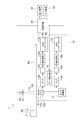
- FIG. 1 is a configuration diagram of an image acquisition device 1 which is a radiation image processing system according to the present embodiment.
- the image acquisition device 1 irradiates the object F transported in the transport direction TD with X-rays (radiation), and obtains the object F based on the X-rays transmitted through the object F.
- It is a device that acquires an captured X-ray transmission image (radiation image).
- the image acquisition device 1 uses an X-ray transmission image to perform foreign matter inspection, weight inspection, inspection inspection, etc. on the object F, and its applications include food inspection, baggage inspection, substrate inspection, battery inspection, and material. Inspection etc. can be mentioned.
- the image acquisition device 1 displays a belt conveyor (conveyor means) 60, an X-ray irradiator (radiation source) 50, an X-ray detection camera (imaging device) 10, and a control device (radiation image processing module) 20. It is configured to include a device 30 and an input device 40 for performing various inputs.
- the radiation image in the embodiment of the present invention is not limited to an X-ray image, but also includes an image by electromagnetic radiation other than X-rays such as ⁇ -rays.
- the belt conveyor 60 has a belt portion on which the object F is placed, and by moving the belt portion in the transport direction TD, the object F is conveyed in the transport direction TD at a predetermined transport speed.
- the transport speed of the object F is, for example, 48 m / min.
- the belt conveyor 60 can change the transport speed to, for example, 24 m / min, 96 m / min, or the like, if necessary. Further, the belt conveyor 60 can change the height position of the belt portion as appropriate to change the distance between the X-ray irradiator 50 and the object F.
- the object F transported by the belt conveyor 60 includes, for example, foods such as meat, seafood, agricultural products, and confectionery, rubber products such as tires, resin products, metal products, resource materials such as minerals, waste, and the like. And various articles such as electronic parts and electronic boards can be mentioned.
- the X-ray irradiator 50 is a device that irradiates (outputs) X-rays to the object F as an X-ray source.
- the X-ray irradiator 50 is a point light source, and irradiates X-rays by diffusing them in a predetermined angle range in a fixed irradiation direction.
- the X-ray irradiator 50 uses the belt conveyor 60 so that the X-ray irradiation direction is directed toward the belt conveyor 60 and the diffused X-rays cover the entire width direction (direction intersecting the transport direction TD) of the object F. It is arranged above the belt conveyor 60 at a predetermined distance from the above. Further, in the X-ray irradiator 50, in the length direction of the object F (direction parallel to the transport direction TD), a predetermined division range in the length direction is set as the irradiation range, and the object F is placed on the belt conveyor 60. By being transported in the transport direction TD, X-rays are irradiated to the entire length direction of the object F.
- the X-ray irradiator 50 has a tube voltage and a tube current set by the control device 20, and irradiates the belt conveyor 60 with X-rays having a predetermined energy and radiation amount corresponding to the set tube voltage and tube current. .. Further, a filter 51 for transmitting a predetermined wavelength range of X-rays is provided in the vicinity of the X-ray irradiator 50 on the belt conveyor 60 side. The filter 51 is not always necessary and may not be necessary.
- the X-ray detection camera 10 detects the X-rays transmitted through the object F among the X-rays irradiated to the object F by the X-ray irradiator 50, and outputs a signal based on the X-rays.
- the X-ray detection camera 10 is a dual-line X-ray camera in which two sets of configurations for detecting X-rays are arranged. In the image acquisition device 1 according to the present embodiment, X-ray transmission images are generated based on the X-rays detected in each line (first line and second line) of the dual-line X-ray camera.
- the two generated X-ray transmission images are subjected to averaging processing, addition processing, or the like to generate a smaller X-ray transmission image based on the X-rays detected in one line. It is possible to acquire a clear (high brightness) image.
- the X-ray detection camera 10 includes a filter 19, scintillators 11a and 11b, line scan cameras 12a and 12b, a sensor control unit 13, amplifiers 14a and 14b, AD converters 15a and 15b, and correction circuits 16a and 16b. , The output interfaces 17a and 17b, and the amplifier control unit 18.
- the scintillator 11a, the line scan camera 12a, the amplifier 14a, the AD converter 15a, the correction circuit 16a, and the output interface 17a are each electrically connected, and are configured according to the first line.
- the scintillator 11b, the line scan camera 12b, the amplifier 14b, the AD converter 15b, the correction circuit 16b, and the output interface 17b are each electrically connected, and have a configuration related to the second line.
- the line scan camera 12a of the first line and the line scan camera 12b of the second line are arranged side by side along the transport direction TD. In the following, the configuration common to the first line and the second line will be described on behalf of the configuration of the first line.
- the scintillator 11a is fixed on the line scan camera 12a by adhesion or the like, and converts X-rays transmitted through the object F into scintillation light.
- the scintillator 11a outputs the scintillation light to the line scan camera 12a.
- the filter 19 transmits a predetermined wavelength region of X-rays toward the scintillator 11a.
- the filter 19 is not always necessary and may not be necessary.
- the line scan camera 12a detects the scintillation light from the scintillator 11a, converts it into an electric charge, and outputs it as a detection signal (electric signal) to the amplifier 14a.
- the line scan camera 12a has a plurality of line sensors arranged in parallel in a direction intersecting the transport direction TD.
- the line sensor is, for example, a CCD (Charge Coupled Device) image sensor, a CMOS (Complementary Metal-Oxide Semiconductor) image sensor, or the like, and includes a plurality of photodiodes.
- the sensor control unit 13 controls the line scan cameras 12a and 12b to repeatedly image the line scan cameras 12a and 12b at a predetermined detection cycle so that the line scan cameras 12a and 12b can image the X-rays transmitted through the same region of the object F. ..
- the predetermined detection cycle is, for example, the distance between the line scan cameras 12a and 12b, the speed of the belt conveyor 60, and the distance between the X-ray irradiator 50 and the object F on the belt conveyor 60 (FOD (Focus Object Distance: radiation source).
- the predetermined period may be set individually based on the pixel width of the photodiode in the direction orthogonal to the pixel arrangement direction of the line sensors of the line scan cameras 12a and 12b. In this case, the distance between the line scan cameras 12a and 12b, the speed of the belt conveyor 60, the distance (FOD) between the X-ray irradiator 50 and the object F on the belt conveyor 60, and the X-ray irradiator 50.
- the deviation (delay time) of the detection cycle between the line scan cameras 12a and 12b may be specified according to the distance (FDD) from the line scan cameras 12a and 12b, and individual cycles may be set for each.
- the amplifier 14a amplifies the detection signal at a predetermined amplification factor to generate an amplification signal, and outputs the amplification signal to the AD converter 15a.
- the set amplification factor is an amplification factor set by the amplifier control unit 18.
- the amplifier control unit 18 sets the set amplification factor of the amplifiers 14a and 14b based on predetermined imaging conditions.
- the AD converter 15a converts the amplified signal (voltage signal) output by the amplifier 14a into a digital signal and outputs it to the correction circuit 16a.
- the correction circuit 16a performs a predetermined correction such as signal amplification on the digital signal, and outputs the corrected digital signal to the output interface 17a.
- the output interface 17a outputs a digital signal to the outside of the X-ray detection camera 10.
- the AD converter, the correction circuit, and the output interface are individually present, but they may be integrated into one.
- the control device 20 is, for example, a computer such as a PC (Personal Computer).
- the control device 20 generates an X-ray transmission image based on the digital signal (amplified signal) output from the X-ray detection camera 10 (more specifically, the output interfaces 17a and 17b).
- the control device 20 generates one X-ray transmission image by averaging or adding the two digital signals output from the output interfaces 17a and 17b.
- the generated X-ray transmission image is output to the display device 30 after being subjected to noise removal processing described later, and is displayed by the display device 30.
- the control device 20 controls the X-ray irradiator 50, the amplifier control unit 18, and the sensor control unit 13.
- the control device 20 of the present embodiment is a device independently provided outside the X-ray detection camera 10, it may be integrated inside the X-ray detection camera 10.
- FIG. 2 shows the hardware configuration of the control device 20.
- the control device 20 physically includes a CPU (Central Processing Unit) 101 as a processor, a RAM (Random Access Memory) 102 or a ROM (Read Only Memory) 103 as a recording medium, and a communication module.
- a computer or the like including the 104 and the input / output module 106 and the like, each of which is electrically connected.
- the control device 20 may include a display, a keyboard, a mouse, a touch panel display, and the like as the input device 40 and the display device 30, or may include a data recording device such as a hard disk drive and a semiconductor memory. Further, the control device 20 may be composed of a plurality of computers.
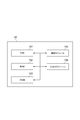
- FIG. 3 is a block diagram showing a functional configuration of the control device 20.
- the control device 20 includes an acquisition unit 201, a specific unit 202, a selection unit 204, and a processing unit 205.
- Each functional unit of the control device 20 shown in FIG. 3 reads a program (radio image processing program of the present embodiment) on hardware such as the CPU 101 and the RAM 102, and under the control of the CPU 101, the communication module 104. , And the input / output module 106 and the like are operated, and data is read and written in the RAM 102.
- the CPU 101 of the control device 20 causes the control device 20 to function as each functional unit of FIG. 3 by executing this computer program, and sequentially executes processing corresponding to the radiographic image processing method described later.
- the CPU may be a single piece of hardware, or may be implemented in programmable logic such as FPGA, such as a soft processor.
- the RAM and ROM may be single-unit hardware, or may be built in programmable logic such as FPGA.
- Various data necessary for executing this computer program and various data generated by executing this computer program are all stored in an internal memory such as ROM 103 and RAM 102, or a storage medium such as a hard disk drive.
- control device 20 stores in advance a plurality of trained models 206 that are read by the CPU 101 to cause the CPU 101 to execute a noise removal process for an X-ray transmission image.
- Each of the plurality of trained models 206 is a learning model by machine learning constructed in advance using image data as teacher data.
- Machine learning includes supervised learning, deep learning, reinforcement learning, neural network learning, and the like.
- the deep learning algorithm the two-dimensional convolutional neural network described in the paper "Beyonda Gaussian Denoiser: Residual Learning of Deep CNN for Image Denoising" by Kai Zhang et al. Is adopted.
- the plurality of trained models 206 may be generated by an external computer or the like and downloaded to the control device 20, or may be generated in the control device 20.
- FIG. 4 shows an example of image data which is teacher data used for constructing the trained model 206.
- the teacher data an X-ray transmission image in which patterns of various thicknesses, various materials, and various resolutions are captured can be used.
- the example shown in FIG. 4 is an example of an X-ray transmission image generated for chicken.
- an X-ray transmission image actually generated by using the image acquisition device 1 for a plurality of types of objects may be used, or image data generated by simulation calculation may be used.
- the X-ray transmission image may be acquired by using an apparatus different from the image acquisition apparatus 1. Further, the X-ray transmission image and the image data generated by the simulation calculation may be used in combination.
- Each of the plurality of trained models 206 is image data obtained for transmitted X-rays having different average energies, and is pre-constructed using image data having a known noise distribution.
- the average energy of X-rays in the image data can be determined by setting the operating conditions of the X-ray irradiator (radiation source) 50 of the image acquisition device 1, the imaging conditions of the image acquisition device 1, etc., or at the time of simulation calculation. By setting the operating conditions or the imaging conditions of the X-ray irradiator 50, different values are set in advance.
- the plurality of trained models 206 indicate the operating conditions of the X-ray irradiator (radiation source) 50 when capturing the X-ray transmission image of the object F, the imaging conditions by the X-ray detection camera 10, and the like. It is constructed by machine learning using a training image which is an X-ray image corresponding to the average energy of X-rays transmitted through the object F calculated based on the condition information as training data (construction step).
- the plurality of trained models 206 have a plurality of frames (for example, 20, It is constructed using (000 frames).
- FIG. 5 is a flowchart showing a procedure for creating image data which is teacher data used for constructing the trained model 206.
- Image data (also called teacher image data), which is teacher data, is created by a computer in the following procedure.
- structure image an image of a structure having a predetermined structure
- an image of a structure having a predetermined structure may be created by simulation calculation.
- an X-ray image of a structure such as a chart having a predetermined structure may be acquired to create a structure image.
- the sigma value which is the standard deviation of the pixel values, is calculated for one pixel selected from the plurality of pixels constituting the structure image (step S102).
- a normal distribution (Poisson distribution) showing a noise distribution is set based on the sigma value obtained in step S102 (step S103).
- step S104 the noise value set at random is calculated along the normal distribution set based on the sigma value in step S103 (step S104). Further, by adding the noise value obtained in step S104 to the pixel value of one pixel, the pixel value constituting the image data which is the teacher data is generated (step S105). The processes from step S102 to step S105 are performed for each of the plurality of pixels constituting the structure image (step S106), and teacher image data to be teacher data is generated (step S107).
- the teacher image data is further required, it is determined that the processes from step S101 to step S107 are to be performed on another structure image (step S108), and another teacher image data to be the teacher data is used.
- the other structure image may be an image of a structure having the same structure or an image of a structure having another structure.
- the structure image is preferably an image with less noise, and ideally, an image without noise is preferable. Therefore, if the structure image is generated by the simulation calculation, many noise-free images can be generated. Therefore, it is effective to generate the structure image by the simulation calculation.
- the acquisition unit 201 acquires an X-ray transmission image captured by irradiating the jig and the object F with X-rays using the image acquisition device 1.
- the jig a flat plate member whose thickness and material are known and whose relationship between the average energy of X-rays and the X-ray transmittance is known, or a jig having a chart imaged at various resolutions. Used. That is, the acquisition unit 201 acquires an X-ray transmission image of the jig captured by using the image acquisition device 1 prior to the observation process of the object F.
- the acquisition unit 201 acquires the X-ray transmission image of the object F captured by the image acquisition device 1 at the timing after the learned model 206 is selected based on the X-ray transmission image of the jig. do.
- the acquisition timing of the X-ray transmission image of the jig and the object F is not limited to the above, and may be simultaneous or vice versa.
- the identification unit 202 specifies the image characteristics of the X-ray transmission image of the jig acquired by the acquisition unit 201. Specifically, the selection unit 204 specifies energy characteristics, noise characteristics, resolution characteristics, frequency characteristics, and the like as image characteristics of the X-ray transmission image.
- the specific portion 202 has the brightness of the X-ray image transmitted through the jig and the brightness of the X-ray image transmitted through the air.
- the X-ray transmittance of one point (or the average of a plurality of points) in the jig is calculated by comparing with. For example, when the brightness of the X-ray image transmitted through the jig is 5,550 and the brightness of the X-ray image transmitted through the air is 15,000, the transmittance is calculated to be 37%.
- the identification unit 202 specifies the average energy of transmitted X-rays (for example, 50 keV) estimated from the transmittance of 37% as the energy characteristics of the X-ray transmitted image of the jig.
- the specific unit 202 may analyze the characteristics at a plurality of points of the jig whose thickness or material changes as the energy characteristics of the X-ray transmission image of the jig.
- FIG. 6 is a diagram showing an example of an X-ray transmission image to be analyzed by the specific unit 202.
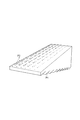
- FIG. 6 is an X-ray transmission image for a jig having a shape in which the thickness changes in steps.
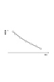
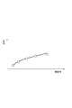
- the specific unit 202 selects a plurality of measurement regions (ROI: Region Of Interest) having different thicknesses from such an X-ray transmission image, analyzes the brightness average value for each of the plurality of measurement areas, and analyzes the thickness-luminance. Acquire the characteristic graph as the energy characteristic.
- FIG. 7 shows an example of the thickness-luminance characteristic graph acquired by the specific unit 202.
- the specific unit 202 can analyze the brightness value and noise for each of a plurality of measurement regions as the noise characteristic of the X-ray transmission image of the jig, and acquire the characteristic graph of the brightness-noise ratio as the noise characteristic. That is, the specific unit 202 selects a plurality of measurement region ROIs having different thicknesses or materials from the X-ray transmission image, analyzes the standard deviation of the brightness values of the plurality of measurement region ROIs, and analyzes the average value of the brightness values, and the brightness-.
- the characteristic graph of SNR (SN ratio) is acquired as a noise characteristic.
- the specific unit 202 may acquire a characteristic graph in which the vertical axis is noise calculated from the standard deviation of the luminance value instead of the above-mentioned characteristic graph of luminance-SNR.
- the specific unit 202 can also acquire the distribution of the resolution in the X-ray transmission image of the jig as a resolution characteristic. Further, the specific unit 202 has a function of acquiring the resolution characteristic of the image after the noise removal processing is performed by applying the plurality of trained models 206 to the X-ray transmission image of the jig.
- FIG. 9 shows an example of an X-ray transmission image used for evaluating the resolution. In this X-ray transmission image, a chart whose resolution changes stepwise along one direction is targeted for imaging. The resolution of the X-ray transfer image can be measured by using MTF (Modulation Transfer Function) or CTF (Contrast Transfer Function).
- the selection unit 204 finally selects the object F from among the plurality of trained models 206 stored in the control device 20 based on the image characteristics acquired by the specific unit 202.
- the trained model 206 used for the noise removal processing of the X-ray transmission image of is selected. That is, the selection unit 204 compares the image characteristics specified by the specific unit 202 with the image characteristics specified from the image data used for constructing the plurality of trained models 206, and both are similar trained models. Select 206.
- the selection unit 204 selects one trained model 206 constructed by the image data of the average energy closest to the value of the average energy of the transmitted X-rays specified by the specific unit 202.
- the selection unit 204 acquires a thickness-brightness characteristic graph for the image data used for constructing the plurality of trained models 206 in the same manner as the identification method by the specific unit 202, and targets the jig.
- the trained model 206 constructed from the image data having the characteristics closest to the thickness-brightness characteristic graph acquired in is selected as the final trained model 206.
- the image characteristics of the image data used for constructing the trained model 206 may refer to those calculated in advance outside the control device 20.
- the selection unit 204 uses the trained model 206 constructed by the image data having the characteristic of the brightness-noise ratio closest to the characteristic of the brightness-noise ratio acquired by the specific unit 202 as the final trained model 206. May be selected as.
- the image characteristics of the image data used for constructing the trained model 206 may be acquired by the selection unit 204 from the image data, or may refer to those calculated in advance outside the control device 20. ..
- the selection unit 204 may select the trained model 206 as the noise characteristic by using the luminance-noise characteristic instead of the luminance-noise ratio characteristic.
- noise factors shots noise, readout noise, etc. that are dominant from the slope of the graph in the region of each signal amount with respect to each signal amount detected by the X-ray detection camera 10 are used.
- the trained model 206 can be selected based on the specific result.
- FIG. 10 is a diagram for explaining the selection function of the trained model based on the image characteristics by the selection unit 204.
- (a) portion characteristic graphs G 1 of the luminance -SNR of each image data used for constructing a plurality of trained models 206, G 2, shows a G 3, part (b) is in addition to these characteristic graphs G 1, G 2, G 3 , shows a characteristic graph G T luminance -SNR of X-ray transmission image of the captured jig. Learning when such characteristics graph G 1, G 2, G 3 , G T the target, the selection unit 204, which is constructed by the nearest characteristic image data of the graph G 2 to the characteristics of the characteristic graph G T It works to select the finished model 206.
- the selection unit 204 During selection, the selection unit 204, between a characteristic graph G T and the characteristic graphs G 1, G 2, G 3 , and calculates an error of SNR of each luminance value of the predetermined intervals, the average of those errors square error (RMSE: root mean squared error) is calculated, and selects the learned model 206 corresponding to the smallest characteristic graph mean square error G 1, G 2, G 3 . Further, the selection unit 204 can also select the trained model 206 in the same manner when selecting using the energy characteristics.
- RMSE root mean squared error
- the selection unit 204 generates an image having relatively excellent characteristics based on the characteristics of the image after applying a plurality of trained models and performing noise removal processing on the X-ray transmission image of the jig. It is also possible to select the trained model 206 used in.
- the selection unit 204 applies a plurality of trained models 206 to the X-ray transmission image obtained by imaging a jig having charts having various resolutions, and the resulting image after noise removal. Evaluate the resolution characteristics of. Then, the selection unit 204 selects the trained model 206 used for the image in which the change in the resolution of each distribution before and after the noise removal processing is the smallest.
- the selection unit 204 evaluates the characteristics of the brightness-noise ratio of the image after noise removal, and selects the trained model 206 used to generate the image having the highest characteristics. You may.
- FIG. 11 shows an example of the structure of the jig used for evaluating the brightness-noise ratio. For example, as a jig, a jig in which foreign substances P2 having various materials and various sizes are scattered in a member P1 whose thickness changes in a step-like manner in one direction can be used.
- FIG. 12 shows an X-ray transmission image obtained for the jig of FIG. 11 after noise removal processing.
- the selection unit 204 selects an image region R1 containing an image of a foreign matter P2 in an X-ray transmission image and an image region R2 not including an image of a foreign matter P2 in the vicinity of the region R1, and minimizes the brightness in the image region R1.
- the value L MIN , the average value L AVE of the brightness in the image region R2, and the standard deviation L SD of the brightness in the image region R2 are calculated.
- the selection unit 204 calculates the brightness-noise ratio CNR for each of the X-ray transmission images after the application of the plurality of trained models 206, and generates an X-ray transmission image having the highest brightness-noise ratio CNR. Select the trained model 206 used.
- the processing unit 205 applies the trained model 206 selected by the selection unit 204 to the X-ray transmission image acquired for the object F, and executes image processing for removing noise to output an output image. Generate. Then, the processing unit 205 outputs the generated output image to the display device 30 or the like.
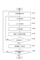
- FIG. 13 is a flowchart showing the procedure of the observation process by the image acquisition device 1.
- the operator (user) of the image acquisition device 1 sets the imaging conditions in the image acquisition device 1 such as the tube voltage of the X-ray irradiator 50 or the gain in the X-ray detection camera 10 (step S1).
- the jig is set in the image acquisition device 1, and the control device 20 acquires an X-ray transmission image for the jig (step S2).
- X-ray transmission images of a plurality of types of jigs may be sequentially acquired.
- control device 20 specifies the image characteristics (energy characteristics, noise characteristics, and resolution characteristics) of the X-ray transmission image of the jig (step S3). Further, the control device 20 applies a plurality of trained models 206 to the X-ray transmission image of the jig, and the image characteristics (resolution characteristics or resolution characteristics) of the respective X-ray transmission images after the application of the plurality of trained models 206 are applied. The brightness-noise ratio value, etc.) is specified (step S4).
- the control device 20 compares the energy characteristics of the X-ray transmission image of the jig with the energy characteristics of the image data used for constructing the trained model 206, and the resolution of the X-ray transmission image of the jig.
- the trained model 206 is selected based on the degree of change before and after the application of the trained model of the characteristic (step S5).
- the trained model 206 may be selected based on the state of change before and after the application of. Further, in step S5, instead of the above processing, the trained model 206 having the highest brightness-noise ratio CNR after applying the trained model of the X-ray transmission image of the jig may be selected.
- step S7 when the object F is set in the image acquisition device 1 and the object F is imaged, an X-ray transmission image of the object F is acquired (step S7).
- the control device 20 applies the finally selected trained model 206 to the X-ray transmission image of the object F, so that noise removal processing is executed on the X-ray transmission image (step S8). ..
- the control device 20 outputs an output image, which is an X-ray transmission image that has been subjected to noise removal processing, to the display device 30 (step S9).
- the image characteristics of the X-ray transmission image of the jig are specified, and based on the image characteristics, a trained model used for noise removal is selected from the trained models constructed in advance. Be selected.
- the characteristics of the X-ray transmission image that changes depending on the operating conditions of the X-ray irradiator 50 in the image acquisition device 1 can be estimated, and the trained model 206 selected according to the estimation result is used for noise removal.
- Noise removal corresponding to the relationship between brightness and noise in an X-ray transmission image can be realized.
- noise in the X-ray transmission image can be effectively removed.
- the X-ray transmission image contains noise derived from X-ray generation. It is conceivable to increase the X-ray dose in order to improve the signal-to-noise ratio of the X-ray transmission image, but in that case, increasing the X-ray dose increases the exposure dose of the sensor and shortens the life of the sensor. There is a problem that the life of the source is shortened, and it is difficult to achieve both an improvement in the SN ratio and a long life. In the present embodiment, since it is not necessary to increase the X dose, it is possible to achieve both an improvement in the SN ratio and a long life.
- the image characteristics of the X-ray transmission image of the jig and the image characteristics of the image data used for constructing the trained model are compared.
- the trained model 206 constructed with the image data corresponding to the image characteristics of the X-ray transmission image of the jig is selected, so that the noise in the X-ray transmission image of the object F can be effectively removed.
- the trained model is selected by using the image characteristics of the image obtained by applying the plurality of trained models 206 to the X-ray transmission image of the jig.
- the trained model 206 is selected based on the image characteristics of the X-ray transmission image of the jig to which the plurality of trained models 206 are actually applied, the noise in the X-ray transmission image of the object F is effectively eliminated. Can be removed.
- energy characteristics or noise characteristics are used as image characteristics.
- the trained model 206 constructed with an image having characteristics similar to the energy characteristics or noise characteristics of the X-ray transmission image of the jig, which changes depending on the imaging conditions of the image acquisition device 1, is selected. As a result, it is possible to remove noise in the X-ray transmission image of the object F corresponding to the change in the conditions of the image acquisition device 1.
- the resolution characteristic or the brightness-noise ratio is also used as the image characteristic. According to such a configuration, by applying the selected trained model 206, it becomes possible to obtain an X-ray transmission image having a good resolution characteristic or a brightness-noise ratio. As a result, it is possible to remove noise in the X-ray transmission image of the object corresponding to the change in the conditions of the image acquisition device 1.
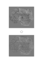
- 14 and 15 show examples of X-ray transmission images before and after the noise removal process acquired by the image acquisition device 1.
- 14 and 15 show images of cheese to which foreign substances such as metal and glass have been added, and images of chicken with bones of various sizes remaining, respectively, on the left side.
- the image before noise processing is shown in, and the image after noise processing is shown on the right side.
- noise removal is effectively performed on various objects.
- the X-ray detection camera 10 has been described as being a dual-line X-ray camera, but the present invention is not limited to this, and a single-line X-ray camera, a dual energy X-ray camera, a TDI (Time Delay Integration) scan X-ray camera, and the like.
- a direct conversion type X-ray camera (a-Se, Si, CdTe, CdZnTe, TlBr, PbI2, etc.) that does not use a scintillator, or an observation type camera that uses an optical lens with a scintillator by lens coupling may be used.
- the X-ray detection camera 10 may be a radiation-sensitive image pickup tube or a radiation-sensitive point sensor.
- the image acquisition device 1 is not limited to the above embodiment, and may be a radiation image processing system such as a CT (Computed Tomography) device that captures an image of an object F in a stationary state. Further, it may be a radiographic image processing system that takes an image while rotating the object F.
- CT Computer Tomography
- jigs in the image acquisition device 1 of the above embodiment, various types of jigs can be used.
- a jig in which flat plate-shaped members P11, P12, P13, and P14 made of different materials are two-dimensionally arranged may be used.
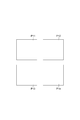
- FIG. 17 even if the member has a shape in which the thickness is one-dimensionally changed in a step shape and the flat plate-shaped members P21, P22, and P23 having different materials are arranged side by side. good.
- a part of the jig may have an opening or a cut shape so that an object F or an object similar to the object F can be imaged at the time of imaging the jig.
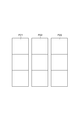
- the object F may be imaged at the time of imaging with the jig, and the trained model may be selected by combining the transparent image of the object with the transparent image of the jig. Further, as shown in the portions (a) to (c) of FIG. 18, the chart is arranged so that the boundary line faces the parallel direction, the diagonal direction, or the vertical direction with respect to the transport direction TD by the belt conveyor 60. A jig having the above may be used.
- the selection unit selects the trained model by comparing the image characteristics with the image characteristics identified from the image data.
- the trained model constructed by the image data corresponding to the image characteristics of the radiation image of the jig is selected, so that the noise in the radiation image of the object can be effectively removed.
- the image characteristics of a plurality of images obtained as a result of applying a plurality of trained models to the radiation image of the jig are specified, and in the selection step, the image characteristics of the plurality of images are used as the basis. It is also preferable to select a trained model.
- the specific unit identifies the image characteristics of a plurality of images obtained as a result of applying a plurality of trained models to the radiation image of the jig, and the selection unit learns based on the image characteristics of the plurality of images. It is also preferable to select a finished model. In this case, since the trained model is selected based on the image characteristics of the radiation image of the jig to which the plurality of trained models are actually applied, noise in the radiation image of the object can be effectively removed.
- the image characteristic is at least one of the energy characteristic, the noise characteristic, and the frequency characteristic, and it is preferable to select a trained model constructed by image data having similar image characteristics in the selection step.
- the image characteristic is at least one of the energy characteristic, the noise characteristic, and the frequency characteristic, and it is preferable that the selection unit selects a trained model constructed by image data having similar image characteristics. be.
- a trained model constructed with an image having characteristics similar to at least one of the energy characteristics, noise characteristics, and frequency characteristics of the radiation image of the jig, which changes depending on the system is selected. As a result, it is possible to remove noise in the radiographic image of the object corresponding to the change in the system conditions.
- the image characteristic is a resolution characteristic or a brightness-noise ratio
- the trained model used to generate an image having a relatively excellent resolution characteristic or the brightness-noise ratio is selected. It is also preferable to prepare further.
- the image characteristic is a resolution characteristic or a brightness-noise ratio
- the selection unit may select a trained model used to generate an image having a relatively excellent resolution characteristic or a brightness-noise ratio. Suitable. According to such a configuration, by applying the selected trained model, it becomes possible to obtain a radiation image having a good resolution characteristic or a brightness-noise ratio. As a result, it is possible to remove noise in the radiographic image of the object corresponding to the change in the system conditions.
- the embodiment uses a radiation image processing method, a trained model, a radiation image processing module, a radiation image processing program, and a radiation image processing system as applications, and can effectively remove noise in a radiation image.
Landscapes
- Physics & Mathematics (AREA)
- General Physics & Mathematics (AREA)
- Health & Medical Sciences (AREA)
- Engineering & Computer Science (AREA)
- Life Sciences & Earth Sciences (AREA)
- General Health & Medical Sciences (AREA)
- Theoretical Computer Science (AREA)
- Analytical Chemistry (AREA)
- Immunology (AREA)
- Pathology (AREA)
- Biochemistry (AREA)
- Chemical & Material Sciences (AREA)
- Toxicology (AREA)
- Software Systems (AREA)
- Molecular Biology (AREA)
- Artificial Intelligence (AREA)
- Computer Vision & Pattern Recognition (AREA)
- Data Mining & Analysis (AREA)
- Evolutionary Computation (AREA)
- Computing Systems (AREA)
- General Engineering & Computer Science (AREA)
- Mathematical Physics (AREA)
- Spectroscopy & Molecular Physics (AREA)
- High Energy & Nuclear Physics (AREA)
- Medical Informatics (AREA)
- Biomedical Technology (AREA)
- Biophysics (AREA)
- Computational Linguistics (AREA)
- Quality & Reliability (AREA)
- Analysing Materials By The Use Of Radiation (AREA)
- Image Processing (AREA)
- Apparatus For Radiation Diagnosis (AREA)
Priority Applications (6)
| Application Number | Priority Date | Filing Date | Title |
|---|---|---|---|
| EP21788256.2A EP4123297B1 (en) | 2020-04-16 | 2021-04-14 | Radiographic image processing method, trained model, radiographic image processing module, radiographic image processing program, and radiographic image processing system |
| CN202180028347.5A CN115398215B (zh) | 2020-04-16 | 2021-04-14 | 放射线图像处理方法、学习完毕模型、放射线图像处理模块、放射线图像处理程序及放射线图像处理系统 |
| ES21788256T ES3026407T3 (en) | 2020-04-16 | 2021-04-14 | Radiographic image processing method, trained model, radiographic image processing module, radiographic image processing program, and radiographic image processing system |
| JP2022515419A JP7546048B2 (ja) | 2020-04-16 | 2021-04-14 | 放射線画像処理方法、学習済みモデル、放射線画像処理モジュール、放射線画像処理プログラム、及び放射線画像処理システム |
| US17/918,397 US12540906B2 (en) | 2020-04-16 | 2021-04-14 | Radiographic image processing method, trained model, radiographic image processing module, radiographic image processing program, and radiographic image processing system |
| KR1020227037165A KR20230003485A (ko) | 2020-04-16 | 2021-04-14 | 방사선 화상 처리 방법, 학습 완료 모델, 방사선 화상 처리 모듈, 방사선 화상 처리 프로그램, 및 방사선 화상 처리 시스템 |
Applications Claiming Priority (2)
| Application Number | Priority Date | Filing Date | Title |
|---|---|---|---|
| JP2020-073578 | 2020-04-16 | ||
| JP2020073578 | 2020-04-16 |
Publications (1)
| Publication Number | Publication Date |
|---|---|
| WO2021210618A1 true WO2021210618A1 (ja) | 2021-10-21 |
Family
ID=78084367
Family Applications (1)
| Application Number | Title | Priority Date | Filing Date |
|---|---|---|---|
| PCT/JP2021/015489 Ceased WO2021210618A1 (ja) | 2020-04-16 | 2021-04-14 | 放射線画像処理方法、学習済みモデル、放射線画像処理モジュール、放射線画像処理プログラム、及び放射線画像処理システム |
Country Status (7)
| Country | Link |
|---|---|
| US (1) | US12540906B2 (https=) |
| EP (1) | EP4123297B1 (https=) |
| JP (1) | JP7546048B2 (https=) |
| KR (1) | KR20230003485A (https=) |
| CN (1) | CN115398215B (https=) |
| ES (1) | ES3026407T3 (https=) |
| WO (1) | WO2021210618A1 (https=) |
Cited By (4)
| Publication number | Priority date | Publication date | Assignee | Title |
|---|---|---|---|---|
| US20240054617A1 (en) * | 2021-02-15 | 2024-02-15 | Hamamatsu Photonics K.K. | Radiographic image processing method, machine-learning method, trained model, machine-learning preprocessing method, radiographic image processing module, radiographic image processing program, and radiographic image processing system |
| WO2024049201A1 (ko) * | 2022-08-31 | 2024-03-07 | 주식회사 엘지에너지솔루션 | 배터리 전극 검사 장치 및 방법 |
| US12540906B2 (en) | 2020-04-16 | 2026-02-03 | Hamamatsu Photonics K.K. | Radiographic image processing method, trained model, radiographic image processing module, radiographic image processing program, and radiographic image processing system |
| US12591072B2 (en) | 2020-04-16 | 2026-03-31 | Hamamatsu Photonics K.K. | Radiographic image acquiring device, radiographic image acquiring system, and radiographic image acquisition method |
Citations (7)
| Publication number | Priority date | Publication date | Assignee | Title |
|---|---|---|---|---|
| JP2006318103A (ja) * | 2005-05-11 | 2006-11-24 | Fuji Photo Film Co Ltd | 画像処理装置および方法並びにプログラム |
| JP2008229161A (ja) * | 2007-03-22 | 2008-10-02 | Fujifilm Corp | 画像成分分離装置、方法、およびプログラム、ならびに、正常画像生成装置、方法、およびプログラム |
| JP2013512024A (ja) * | 2009-11-25 | 2013-04-11 | コーニンクレッカ フィリップス エレクトロニクス エヌ ヴィ | 向上された画像データ/線量低減 |
| CN109697476A (zh) * | 2019-02-01 | 2019-04-30 | 重庆大学 | 一种基于深度学习的x射线光子计数探测器一致性校准方法 |
| JP2019091393A (ja) | 2017-11-10 | 2019-06-13 | アジア航測株式会社 | 赤色立体地図画像を用いた点群種類推定装置及び赤色立体地図画像を用いた点群種類推定プログラム |
| JP2019111322A (ja) * | 2017-12-20 | 2019-07-11 | キヤノンメディカルシステムズ株式会社 | 医用信号処理装置 |
| WO2020031984A1 (ja) * | 2018-08-08 | 2020-02-13 | Blue Tag株式会社 | 部品の検査方法及び検査システム |
Family Cites Families (111)
| Publication number | Priority date | Publication date | Assignee | Title |
|---|---|---|---|---|
| US5335260A (en) * | 1992-11-25 | 1994-08-02 | Arnold Ben A | Calibration phantom and improved method of quantifying calcium and bone density using same |
| FR2705785B1 (fr) * | 1993-05-28 | 1995-08-25 | Schlumberger Ind Sa | Procédé pour déterminer la fonction d'atténuation d'un objet par rapport à la transmission d'une épaisseur de référence d'un matériau de référence et dispositif pour la mise en Óoeuvre du procédé. |
| US5585603A (en) * | 1993-12-23 | 1996-12-17 | Design Systems, Inc. | Method and system for weighing objects using X-rays |
| US5565678A (en) * | 1995-06-06 | 1996-10-15 | Lumisys, Inc. | Radiographic image quality assessment utilizing a stepped calibration target |
| US5917877A (en) * | 1997-09-05 | 1999-06-29 | Cyberlogic, Inc. | Plain x-ray bone densitometry apparatus and method |
| DE19812055C2 (de) * | 1998-03-19 | 2002-08-08 | Heimann Systems Gmbh & Co | Bildverarbeitung zur Materialerkennung mittels Röntgenstrahlungen |
| US6315447B1 (en) * | 1998-12-22 | 2001-11-13 | Bio-Imaging Technologies, Inc. | Variable composition phantom simulating varying degrees of body fat for dual energy x-ray machine calibration |
| US6201850B1 (en) * | 1999-01-26 | 2001-03-13 | Agilent Technologies, Inc. | Enhanced thickness calibration and shading correction for automatic X-ray inspection |
| US6231231B1 (en) * | 1999-06-24 | 2001-05-15 | General Electric Company | Modular interchangeable phantoms for multiple x-ray systems |
| US6269142B1 (en) * | 1999-08-11 | 2001-07-31 | Steven W. Smith | Interrupted-fan-beam imaging |
| JP2001099941A (ja) | 1999-09-30 | 2001-04-13 | Hitachi Metals Ltd | 放射線遮蔽板、放射線検出器及び放射線遮蔽板の製造方法 |
| BRPI0014974B1 (pt) * | 1999-10-21 | 2015-06-23 | Foss Analytical As | "método e aparelho de determinação de propriedades de um meio de alimento ou ração e método para a calibração de aparelho" |
| US6347131B1 (en) * | 1999-11-02 | 2002-02-12 | Cintex Limited | Non-contact volume measurement |
| US6173038B1 (en) * | 1999-12-01 | 2001-01-09 | Cyberlogic, Inc. | Plain x-ray bone densitometry apparatus and method |
| JP3629397B2 (ja) * | 2000-03-28 | 2005-03-16 | 松下電器産業株式会社 | 接合検査装置及び方法、並びに接合検査方法を実行させるプログラムを記録した記録媒体 |
| US7050534B2 (en) * | 2000-08-29 | 2006-05-23 | Imaging Therapeutics, Inc. | Methods and devices for quantitative analysis of x-ray images |
| US7467892B2 (en) * | 2000-08-29 | 2008-12-23 | Imaging Therapeutics, Inc. | Calibration devices and methods of use thereof |
| US6398408B1 (en) * | 2000-12-07 | 2002-06-04 | Ge Medical Systems Global Technology Company, Llc | Automated image chain geometric quantification |
| DE60226129T2 (de) * | 2001-02-23 | 2009-07-02 | Koninklijke Philips Electronics N.V. | Verfahren und system zur bestimmung der dichte eines volumens in einem bilddatensatz |
| US6370223B1 (en) * | 2001-04-06 | 2002-04-09 | Ut-Battelle, Llc | Automatic detection of bone fragments in poultry using multi-energy x-rays |
| JP3656566B2 (ja) * | 2001-04-17 | 2005-06-08 | 株式会社島津製作所 | 放射線検査装置 |
| JP2002310946A (ja) * | 2001-04-17 | 2002-10-23 | Shimadzu Corp | 放射線検査装置 |
| US6516045B2 (en) * | 2001-05-04 | 2003-02-04 | The Regents Of The University Of California | Device and method for determining proportions of body materials |
| US6632020B2 (en) * | 2001-10-12 | 2003-10-14 | General Electric Company | Method and apparatus for calibrating an imaging system |
| JP2003167060A (ja) | 2001-11-30 | 2003-06-13 | Toshiba Corp | X線平面検出器 |
| US6570955B1 (en) * | 2002-01-08 | 2003-05-27 | Cyberlogic, Inc. | Digital x-ray material testing and bone densitometry apparatus and method |
| US7311440B2 (en) * | 2004-03-31 | 2007-12-25 | Cyber Medical Imaging, Inc. | Anatomically conforming intraoral dental radiographic sensor |
| DE102004017149A1 (de) * | 2004-04-02 | 2005-10-20 | Fraunhofer Ges Forschung | Verfahren und Vorrichtung zur Bestimmung eines Objektmaterials |
| JP4565896B2 (ja) * | 2004-06-11 | 2010-10-20 | 株式会社イシダ | X線検査装置 |
| CN1906480B (zh) * | 2004-06-24 | 2012-08-08 | 株式会社石田 | X射线检查装置和x射线检查装置的图像处理顺序的生成方法 |
| JP4585907B2 (ja) * | 2005-04-28 | 2010-11-24 | 株式会社イシダ | X線検査装置 |
| JP5148285B2 (ja) * | 2005-11-16 | 2013-02-20 | 株式会社イシダ | X線検査装置 |
| US7746976B2 (en) * | 2005-12-30 | 2010-06-29 | Carestream Health, Inc. | Bone mineral density assessment using mammography system |
| WO2007114470A1 (ja) * | 2006-04-04 | 2007-10-11 | Hitachi Medical Corporation | X線ctスキャンシミュレータ装置、x線ct装置、及びx線ctスキャンシミュレータプログラム |
| JP5041751B2 (ja) * | 2006-07-24 | 2012-10-03 | 株式会社イシダ | X線検査装置およびx線検査プログラム |
| US7991110B2 (en) * | 2007-02-08 | 2011-08-02 | Ishida Co., Ltd. | Weight inspection apparatus and weight inspection system provided therewith |
| JP5559471B2 (ja) * | 2008-11-11 | 2014-07-23 | 浜松ホトニクス株式会社 | 放射線検出装置、放射線画像取得システム、放射線検査システム、及び放射線検出方法 |
| JP5368772B2 (ja) * | 2008-11-11 | 2013-12-18 | 浜松ホトニクス株式会社 | 放射線検出装置、放射線画像取得システム及び放射線の検出方法 |
| JP5418599B2 (ja) | 2009-10-21 | 2014-02-19 | 株式会社島津製作所 | 放射線撮像装置 |
| US8077827B2 (en) * | 2010-02-23 | 2011-12-13 | Test Research, Inc. | Method for thickness calibration and measuring thickness of material |
| JP2011172847A (ja) | 2010-02-25 | 2011-09-08 | Fujifilm Corp | 放射線画像生成装置及び放射線画像生成方法 |
| KR101180698B1 (ko) * | 2010-04-22 | 2012-09-07 | 국방과학연구소 | 탄소/탄소 재료의 내부 밀도 분포 측정 방법 및 그의 표준밀도시편 제작방법 |
| CN102297873A (zh) * | 2011-05-03 | 2011-12-28 | 杭州一二八医院 | 利用软x射线显微成像进行癌细胞图形识别的方法 |
| JP2013017511A (ja) | 2011-07-07 | 2013-01-31 | Toshiba Corp | 画像処理装置および方法、x線診断装置 |
| JP6100772B2 (ja) | 2011-07-15 | 2017-03-22 | コーニンクレッカ フィリップス エヌ ヴェKoninklijke Philips N.V. | 画像処理方法及びコンピューティング装置 |
| US8858076B2 (en) * | 2011-07-19 | 2014-10-14 | Sandia Corporation | Multi-step contrast sensitivity gauge |
| US20130051516A1 (en) | 2011-08-31 | 2013-02-28 | Carestream Health, Inc. | Noise suppression for low x-ray dose cone-beam image reconstruction |
| EA201200255A1 (ru) | 2012-02-22 | 2013-08-30 | Закрытое Акционерное Общество "Импульс" | Способ подавления шума цифровых рентгенограмм |
| US8983234B2 (en) | 2012-09-28 | 2015-03-17 | Varian Medical Systems, Inc. | Method and apparatus pertaining to using imaging information to identify a spectrum |
| JP6112915B2 (ja) | 2013-03-06 | 2017-04-12 | キヤノン株式会社 | 放射線撮影装置及び放射線撮影装置の制御方法 |
| JP6070939B2 (ja) | 2013-03-07 | 2017-02-01 | 富士フイルム株式会社 | 放射線画像撮影装置および方法 |
| JP6071144B2 (ja) | 2013-07-31 | 2017-02-01 | 富士フイルム株式会社 | 放射線画像解析装置および方法並びにプログラム |
| JP6442154B2 (ja) | 2014-04-23 | 2018-12-19 | 浜松ホトニクス株式会社 | 画像取得装置及び画像取得方法 |
| US9615808B2 (en) * | 2014-05-27 | 2017-04-11 | Koninklijke Philips N.V. | Method and radiography system for grid-like contrast enhancement |
| KR20150145633A (ko) | 2014-06-20 | 2015-12-30 | 삼성전자주식회사 | 엑스선 영상 장치 및 그 제어 방법 |
| JP6525772B2 (ja) * | 2015-06-30 | 2019-06-05 | キヤノン株式会社 | 画像処理装置、画像処理方法、放射線撮影システムおよび画像処理プログラム |
| JP2017051395A (ja) * | 2015-09-09 | 2017-03-16 | 富士フイルム株式会社 | 放射線画像処理装置、方法およびプログラム |
| EP3358375B1 (en) | 2015-09-30 | 2023-09-13 | Hamamatsu Photonics K.K. | Radiographic image acquisition system and radiographic image acquisition method |
| JP6590381B2 (ja) | 2015-10-23 | 2019-10-16 | 株式会社ジョブ | X線装置、データ処理装置及びデータ処理方法 |
| JP6730424B2 (ja) * | 2016-03-31 | 2020-07-29 | 株式会社ジョブ | X線検出システム、x線装置、並びに、x線検出データを処理する装置及び方法 |
| JP2017185007A (ja) * | 2016-04-05 | 2017-10-12 | 株式会社島津製作所 | 放射線撮影装置、放射線画像の対象物検出プログラムおよび放射線画像における対象物検出方法 |
| WO2017223560A1 (en) | 2016-06-24 | 2017-12-28 | Rensselaer Polytechnic Institute | Tomographic image reconstruction via machine learning |
| US10242443B2 (en) * | 2016-11-23 | 2019-03-26 | General Electric Company | Deep learning medical systems and methods for medical procedures |
| JP6747948B2 (ja) * | 2016-11-25 | 2020-08-26 | 浜松ホトニクス株式会社 | 放射線検出装置、放射線画像取得装置、及び放射線画像の取得方法。 |
| JP2020096646A (ja) | 2016-12-05 | 2020-06-25 | キヤノン株式会社 | 放射線撮影装置、放射線撮影システム、放射線撮影方法、及びプログラム |
| JP7123927B2 (ja) | 2016-12-06 | 2022-08-23 | コーニンクレッカ フィリップス エヌ ヴェ | 交互打ち消しを使用する画像ノイズ推定 |
| JP2018117900A (ja) | 2017-01-25 | 2018-08-02 | キヤノン株式会社 | 放射線撮影装置、放射線撮影システム、放射線撮影方法、及びプログラム |
| JP7169094B2 (ja) | 2017-06-01 | 2022-11-10 | 株式会社東芝 | 画像処理システム及び医用情報処理システム |
| EP3435326B1 (en) * | 2017-07-27 | 2020-02-19 | Siemens Healthcare GmbH | Method for processing at least one x-ray image |
| CN107595312B (zh) | 2017-08-31 | 2020-12-04 | 上海联影医疗科技股份有限公司 | 模型生成方法、图像处理方法及医学成像设备 |
| US10803555B2 (en) * | 2017-08-31 | 2020-10-13 | Shanghai United Imaging Healthcare Co., Ltd. | System and method for determining a trained neural network model for scattering correction |
| CN107516330B (zh) | 2017-08-31 | 2021-02-09 | 上海联影医疗科技股份有限公司 | 模型生成方法、图像处理方法及医学成像设备 |
| JP2019045235A (ja) | 2017-08-31 | 2019-03-22 | 株式会社Ihiエアロスペース | 画像検査システム、画像検査方法及び画像検査用プログラム |
| DE102017217543B4 (de) | 2017-10-02 | 2020-01-09 | Siemens Healthcare Gmbh | Verfahren und System zur Klassifikation von Materialien mittels maschinellen Lernens |
| US11517197B2 (en) * | 2017-10-06 | 2022-12-06 | Canon Medical Systems Corporation | Apparatus and method for medical image reconstruction using deep learning for computed tomography (CT) image noise and artifacts reduction |
| US10803984B2 (en) * | 2017-10-06 | 2020-10-13 | Canon Medical Systems Corporation | Medical image processing apparatus and medical image processing system |
| US11126914B2 (en) | 2017-10-11 | 2021-09-21 | General Electric Company | Image generation using machine learning |
| CN111263882B (zh) | 2017-10-24 | 2023-07-14 | 世高株式会社 | 电磁波检测组件、电磁波检测组件阵列和无损检查设备 |
| CN107871332A (zh) | 2017-11-09 | 2018-04-03 | 南京邮电大学 | 一种基于残差学习的ct稀疏重建伪影校正方法及系统 |
| JP6987352B2 (ja) | 2017-11-17 | 2021-12-22 | 富士フイルムヘルスケア株式会社 | 医用画像処理装置および医用画像処理方法 |
| EP3509013B1 (en) | 2018-01-04 | 2025-12-24 | Augmedics Inc. | Identification of a predefined object in a set of images from a medical image scanner during a surgical procedure |
| JP6569069B1 (ja) | 2018-03-14 | 2019-09-04 | 株式会社 システムスクエア | 検査装置 |
| JP6969472B2 (ja) | 2018-03-23 | 2021-11-24 | トヨタ自動車株式会社 | 検査方法 |
| CN110197474B (zh) * | 2018-03-27 | 2023-08-25 | 腾讯科技(深圳)有限公司 | 图像处理方法和装置及神经网络模型的训练方法 |
| US10820197B2 (en) | 2018-05-08 | 2020-10-27 | At&T Intellectual Property I, L.P. | Selective disablement of SIP encryption for lawful intercept |
| JP7262933B2 (ja) | 2018-05-25 | 2023-04-24 | キヤノンメディカルシステムズ株式会社 | 医用情報処理システム、医用情報処理装置、放射線診断装置、超音波診断装置、学習用データの生産方法及びプログラム |
| JP7282487B2 (ja) | 2018-06-07 | 2023-05-29 | キヤノンメディカルシステムズ株式会社 | 医用画像診断装置 |
| US10888296B2 (en) * | 2018-06-29 | 2021-01-12 | Shanghai United Imaging Healthcare Co., Ltd. | Methods and systems for modulating radiation dose |
| JP7199850B2 (ja) * | 2018-06-29 | 2023-01-06 | キヤノンメディカルシステムズ株式会社 | 医用情報処理装置 |
| KR102917833B1 (ko) | 2018-08-15 | 2026-01-28 | 에이에스엠엘 네델란즈 비.브이. | 원시 이미지들로부터 고품질 평균 sem 이미지들의 자동 선택 시 기계 학습 활용 |
| US10430708B1 (en) * | 2018-08-17 | 2019-10-01 | Aivitae LLC | System and method for noise-based training of a prediction model |
| US10949951B2 (en) | 2018-08-23 | 2021-03-16 | General Electric Company | Patient-specific deep learning image denoising methods and systems |
| JP7488037B2 (ja) * | 2018-10-24 | 2024-05-21 | キヤノンメディカルシステムズ株式会社 | 医用画像診断装置、医用画像診断方法、およびプログラム |
| CN109544477A (zh) | 2018-11-23 | 2019-03-29 | 南通大学 | 基于自适应字典学习稀疏表示的图像去噪算法 |
| US11436720B2 (en) * | 2018-12-28 | 2022-09-06 | Shanghai United Imaging Intelligence Co., Ltd. | Systems and methods for generating image metric |
| JP7302988B2 (ja) * | 2019-03-07 | 2023-07-04 | 富士フイルムヘルスケア株式会社 | 医用撮像装置、医用画像処理装置、及び、医用画像処理プログラム |
| JP7211223B2 (ja) * | 2019-04-08 | 2023-01-24 | コニカミノルタ株式会社 | 位置合わせ案内装置、放射線撮影システム及びプログラム |
| US11195277B2 (en) * | 2019-04-25 | 2021-12-07 | GE Precision Healthcare LLC | Systems and methods for generating normative imaging data for medical image processing using deep learning |
| JP7446736B2 (ja) * | 2019-08-09 | 2024-03-11 | キヤノンメディカルシステムズ株式会社 | 医用データ処理装置および医用画像診断装置 |
| WO2021028366A1 (en) | 2019-08-14 | 2021-02-18 | Asml Netherlands B.V. | Cross-talk cancellation in multiple charged-particle beam inspection |
| US11324472B2 (en) * | 2019-08-26 | 2022-05-10 | Siemens Medical Solutions Usa, Inc. | Energy-based scatter correction for PET sinograms |
| US11798159B2 (en) * | 2019-09-20 | 2023-10-24 | The Board Of Trustees Of The Leland Stanford Junior University | Systems and methods for radiology image classification from noisy images |
| US11386592B2 (en) * | 2019-12-20 | 2022-07-12 | Varian Medical Systems International Ag | Tomographic image analysis using artificial intelligence (AI) engines |
| US11972559B2 (en) * | 2020-02-13 | 2024-04-30 | Fujifilm Corporation | Radiographic image processing device, radiographic image processing method, and radiographic image processing program |
| KR20230003484A (ko) | 2020-04-16 | 2023-01-06 | 하마마츠 포토닉스 가부시키가이샤 | 방사선 화상 처리 방법, 학습 완료 모델, 방사선 화상 처리 모듈, 방사선 화상 처리 프로그램, 방사선 화상 처리 시스템, 및 기계 학습 방법 |
| EP4130724A4 (en) | 2020-04-16 | 2024-06-12 | Hamamatsu Photonics K.K. | X-RAY IMAGE ACQUISITION DEVICE, X-RAY IMAGE ACQUISITION SYSTEM AND X-RAY IMAGE ACQUISITION METHOD |
| CN115398215B (zh) | 2020-04-16 | 2025-12-02 | 浜松光子学株式会社 | 放射线图像处理方法、学习完毕模型、放射线图像处理模块、放射线图像处理程序及放射线图像处理系统 |
| WO2021232195A1 (en) * | 2020-05-18 | 2021-11-25 | Shanghai United Imaging Healthcare Co., Ltd. | Systems and methods for image optimization |
| JP7395523B2 (ja) | 2021-02-02 | 2023-12-11 | 富士フイルムヘルスケア株式会社 | 医用画像処理装置および医用画像処理方法 |
| JP7837722B2 (ja) * | 2021-03-31 | 2026-03-31 | キヤノン株式会社 | 放射線撮影システム、放射線撮影方法、及び、プログラム |
| US12243127B2 (en) * | 2021-04-07 | 2025-03-04 | Canon Medical Systems Corporation | Medical image processing method, medical image processing apparatus, and computer readable non-volatile storage medium storing medical image processing program |
-
2021
- 2021-04-14 CN CN202180028347.5A patent/CN115398215B/zh active Active
- 2021-04-14 EP EP21788256.2A patent/EP4123297B1/en active Active
- 2021-04-14 JP JP2022515419A patent/JP7546048B2/ja active Active
- 2021-04-14 US US17/918,397 patent/US12540906B2/en active Active
- 2021-04-14 ES ES21788256T patent/ES3026407T3/es active Active
- 2021-04-14 KR KR1020227037165A patent/KR20230003485A/ko active Pending
- 2021-04-14 WO PCT/JP2021/015489 patent/WO2021210618A1/ja not_active Ceased
Patent Citations (7)
| Publication number | Priority date | Publication date | Assignee | Title |
|---|---|---|---|---|
| JP2006318103A (ja) * | 2005-05-11 | 2006-11-24 | Fuji Photo Film Co Ltd | 画像処理装置および方法並びにプログラム |
| JP2008229161A (ja) * | 2007-03-22 | 2008-10-02 | Fujifilm Corp | 画像成分分離装置、方法、およびプログラム、ならびに、正常画像生成装置、方法、およびプログラム |
| JP2013512024A (ja) * | 2009-11-25 | 2013-04-11 | コーニンクレッカ フィリップス エレクトロニクス エヌ ヴィ | 向上された画像データ/線量低減 |
| JP2019091393A (ja) | 2017-11-10 | 2019-06-13 | アジア航測株式会社 | 赤色立体地図画像を用いた点群種類推定装置及び赤色立体地図画像を用いた点群種類推定プログラム |
| JP2019111322A (ja) * | 2017-12-20 | 2019-07-11 | キヤノンメディカルシステムズ株式会社 | 医用信号処理装置 |
| WO2020031984A1 (ja) * | 2018-08-08 | 2020-02-13 | Blue Tag株式会社 | 部品の検査方法及び検査システム |
| CN109697476A (zh) * | 2019-02-01 | 2019-04-30 | 重庆大学 | 一种基于深度学习的x射线光子计数探测器一致性校准方法 |
Non-Patent Citations (1)
| Title |
|---|
| See also references of EP4123297A4 |
Cited By (5)
| Publication number | Priority date | Publication date | Assignee | Title |
|---|---|---|---|---|
| US12540906B2 (en) | 2020-04-16 | 2026-02-03 | Hamamatsu Photonics K.K. | Radiographic image processing method, trained model, radiographic image processing module, radiographic image processing program, and radiographic image processing system |
| US12591072B2 (en) | 2020-04-16 | 2026-03-31 | Hamamatsu Photonics K.K. | Radiographic image acquiring device, radiographic image acquiring system, and radiographic image acquisition method |
| US20240054617A1 (en) * | 2021-02-15 | 2024-02-15 | Hamamatsu Photonics K.K. | Radiographic image processing method, machine-learning method, trained model, machine-learning preprocessing method, radiographic image processing module, radiographic image processing program, and radiographic image processing system |
| WO2024049201A1 (ko) * | 2022-08-31 | 2024-03-07 | 주식회사 엘지에너지솔루션 | 배터리 전극 검사 장치 및 방법 |
| EP4582793A4 (en) * | 2022-08-31 | 2025-12-31 | Lg Energy Solution Ltd | DEVICE AND METHOD FOR INSPECTING A BATTERY ELECTRODE |
Also Published As
| Publication number | Publication date |
|---|---|
| JPWO2021210618A1 (https=) | 2021-10-21 |
| US12540906B2 (en) | 2026-02-03 |
| CN115398215B (zh) | 2025-12-02 |
| KR20230003485A (ko) | 2023-01-06 |
| EP4123297B1 (en) | 2025-03-05 |
| EP4123297A1 (en) | 2023-01-25 |
| CN115398215A (zh) | 2022-11-25 |
| EP4123297C0 (en) | 2025-03-05 |
| EP4123297A4 (en) | 2024-04-17 |
| JP7546048B2 (ja) | 2024-09-05 |
| US20230136930A1 (en) | 2023-05-04 |
| ES3026407T3 (en) | 2025-06-11 |
Similar Documents
| Publication | Publication Date | Title |
|---|---|---|
| JP7546048B2 (ja) | 放射線画像処理方法、学習済みモデル、放射線画像処理モジュール、放射線画像処理プログラム、及び放射線画像処理システム | |
| JP7546047B2 (ja) | 放射線画像処理方法、学習済みモデル、放射線画像処理モジュール、放射線画像処理プログラム、放射線画像処理システム、及び機械学習方法 | |
| KR20220149677A (ko) | 광자-카운팅 x-선 검출기들을 위한 스펙트럼 파일업 보정 | |
| JP7712967B2 (ja) | 放射線画像処理方法、機械学習方法、学習済みモデル、機械学習の前処理方法、放射線画像処理モジュール、放射線画像処理プログラム、及び放射線画像処理システム | |
| CN115427795B (zh) | 放射线图像取得装置、放射线图像取得系统及放射线图像取得方法 | |
| EP4357818A1 (en) | Radiographic image acquiring device, radiographic image acquiring system, and radiographic image acquisition method | |
| EP4623827A1 (en) | Image processing method, training method, trained model, radiological image processing module, radiological image processing program, and radiological image processing system | |
| TWI885189B (zh) | 放射線圖像處理方法、學習完成模型、放射線圖像處理模組、放射線圖像處理程式、放射線圖像處理系統及機器學習方法 | |
| TW202307785A (zh) | 放射線圖像處理方法、學習完成模型、放射線圖像處理模組、放射線圖像處理程式及放射線圖像處理系統 | |
| EP4679360A1 (en) | Image processing method, image processing device, and image processing program |
Legal Events
| Date | Code | Title | Description |
|---|---|---|---|
| 121 | Ep: the epo has been informed by wipo that ep was designated in this application |
Ref document number: 21788256 Country of ref document: EP Kind code of ref document: A1 |
|
| ENP | Entry into the national phase |
Ref document number: 2022515419 Country of ref document: JP Kind code of ref document: A |
|
| ENP | Entry into the national phase |
Ref document number: 2021788256 Country of ref document: EP Effective date: 20221020 |
|
| NENP | Non-entry into the national phase |
Ref country code: DE |
|
| WWG | Wipo information: grant in national office |
Ref document number: 17918397 Country of ref document: US |