WO2021210554A1 - 積載形トラッククレーン及びブームの限界旋回角算出方法 - Google Patents
積載形トラッククレーン及びブームの限界旋回角算出方法 Download PDFInfo
- Publication number
- WO2021210554A1 WO2021210554A1 PCT/JP2021/015241 JP2021015241W WO2021210554A1 WO 2021210554 A1 WO2021210554 A1 WO 2021210554A1 JP 2021015241 W JP2021015241 W JP 2021015241W WO 2021210554 A1 WO2021210554 A1 WO 2021210554A1
- Authority
- WO
- WIPO (PCT)
- Prior art keywords
- boom
- turning angle
- outrigger
- load
- truck crane
- Prior art date
- Legal status (The legal status is an assumption and is not a legal conclusion. Google has not performed a legal analysis and makes no representation as to the accuracy of the status listed.)
- Ceased
Links
Images



Classifications
-
- B—PERFORMING OPERATIONS; TRANSPORTING
- B66—HOISTING; LIFTING; HAULING
- B66C—CRANES; LOAD-ENGAGING ELEMENTS OR DEVICES FOR CRANES, CAPSTANS, WINCHES, OR TACKLES
- B66C23/00—Cranes comprising essentially a beam, boom, or triangular structure acting as a cantilever and mounted for translatory of swinging movements in vertical or horizontal planes or a combination of such movements, e.g. jib-cranes, derricks, tower cranes
- B66C23/18—Cranes comprising essentially a beam, boom, or triangular structure acting as a cantilever and mounted for translatory of swinging movements in vertical or horizontal planes or a combination of such movements, e.g. jib-cranes, derricks, tower cranes specially adapted for use in particular purposes
- B66C23/36—Cranes comprising essentially a beam, boom, or triangular structure acting as a cantilever and mounted for translatory of swinging movements in vertical or horizontal planes or a combination of such movements, e.g. jib-cranes, derricks, tower cranes specially adapted for use in particular purposes mounted on road or rail vehicles; Manually-movable jib-cranes for use in workshops; Floating cranes
-
- B—PERFORMING OPERATIONS; TRANSPORTING
- B66—HOISTING; LIFTING; HAULING
- B66C—CRANES; LOAD-ENGAGING ELEMENTS OR DEVICES FOR CRANES, CAPSTANS, WINCHES, OR TACKLES
- B66C23/00—Cranes comprising essentially a beam, boom, or triangular structure acting as a cantilever and mounted for translatory of swinging movements in vertical or horizontal planes or a combination of such movements, e.g. jib-cranes, derricks, tower cranes
- B66C23/62—Constructional features or details
- B66C23/72—Counterweights or supports for balancing lifting couples
- B66C23/78—Supports, e.g. outriggers, for mobile cranes
-
- B—PERFORMING OPERATIONS; TRANSPORTING
- B66—HOISTING; LIFTING; HAULING
- B66C—CRANES; LOAD-ENGAGING ELEMENTS OR DEVICES FOR CRANES, CAPSTANS, WINCHES, OR TACKLES
- B66C23/00—Cranes comprising essentially a beam, boom, or triangular structure acting as a cantilever and mounted for translatory of swinging movements in vertical or horizontal planes or a combination of such movements, e.g. jib-cranes, derricks, tower cranes
- B66C23/88—Safety gear
-
- B—PERFORMING OPERATIONS; TRANSPORTING
- B66—HOISTING; LIFTING; HAULING
- B66C—CRANES; LOAD-ENGAGING ELEMENTS OR DEVICES FOR CRANES, CAPSTANS, WINCHES, OR TACKLES
- B66C2700/00—Cranes
- B66C2700/03—Cranes with arms or jibs; Multiple cranes
- B66C2700/0321—Travelling cranes
- B66C2700/0357—Cranes on road or off-road vehicles, on trailers or towed vehicles; Cranes on wheels or crane-trucks
- B66C2700/0378—Construction details related to the travelling, to the supporting of the crane or to the blocking of the axles; Outriggers; Coupling of the travelling mechamism to the crane mechanism
Definitions
- the present invention relates to a method for calculating the limit turning angle of a loaded truck crane and a boom.
- Patent Document 1 a load-type truck crane in which a crane device is mounted on a vehicle having a loading platform has been known (see Patent Document 1).
- the limit turning angle at which the crane can turn without the vehicle tipping differs depending on the boom length, turning angle, undulation angle, suspended load, load, and the like.
- An object of the present invention is to provide a method for calculating the limit turning angle of a loaded truck crane and a boom that can improve safety.
- the loading type truck crane according to the present invention is An outrigger device that is mounted on the vehicle and includes right and left outriggers that can be expanded and contracted in the width direction of the vehicle.
- the boom mounted on the vehicle so that it can turn, When the boom is turned from the reference position, the limit turning angle of the boom is based on the jack reaction force of the reverse overturned outrigger, which is the outrigger located on the opposite side of the right outrigger and the left outrigger in the vehicle width direction.
- a turning angle calculation device that obtains To be equipped.
- the method for calculating the limit turning angle of the boom according to the present invention is as follows. Limits of booms performed by the computing unit of a loaded truck crane, which includes an outrigger device that is mounted on the vehicle and includes right and left outriggers that can expand and contract in the vehicle width direction, and a boom that is mounted on the vehicle so that it can turn. It is a turning angle calculation method, In the state where the boom is turned from the reference position, the step of finding the jack reaction force of the reverse inversion side outrigger, which is the outrigger arranged on the opposite side of the boom in the vehicle width direction among the right side outrigger and the left side outrigger, It includes a step of finding the limit turning angle of the boom based on the jack reaction force.
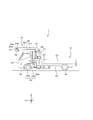
- FIG. 1 is a side view of the loaded truck crane according to the first embodiment.
- FIG. 2 is a plan view of a loaded truck crane.
- FIG. 3 is a block diagram of a turning angle calculation device for a loaded truck crane.
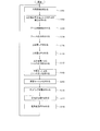
- FIG. 4 is a flowchart for explaining a method of calculating the limit turning angle.
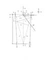
- FIG. 5 is a schematic plan view of a loaded truck crane.
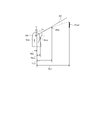
- FIG. 6 is a schematic view of the crane device.
- FIG. 7 is a flowchart for explaining the limit turning angle calculation method according to the second embodiment.
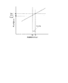
- FIG. 8 is a diagram showing an example of the reaction force-load relationship.
- FIG. 1 is a side view of the loading type truck crane C according to the first embodiment.
- FIG. 2 is a plan view of the loaded truck crane C.
- the loaded truck crane C includes a vehicle 10 and a crane device 20.
- a Cartesian coordinate system (X, Y, Z) will be used for convenience of description.
- the Cartesian coordinate system (X, Y, Z) shown in each figure is a common Cartesian coordinate system.
- the front-rear direction, the left-right direction, and the up-down direction mean each direction in the vehicle 10 without particular notice.
- the front-back direction coincides with the X direction in the Cartesian coordinate system (X, Y, Z).
- the left-right direction coincides with the Y direction in the Cartesian coordinate system (X, Y, Z).
- the vertical direction coincides with the Z direction in the Cartesian coordinate system (X, Y, Z).
- the vehicle 10 is a general-purpose truck and has a traveling function.
- a vehicle 10 has a frame 100, a driver's cab 101, a loading platform 102, a pair of front wheels 103, and a pair of rear wheels 104.
- the frame 100 extends in the front-rear direction of the vehicle.
- the driver's cab 101 is fixed to the upper side of the front end portion of the frame 100.
- the loading platform 102 is a box-shaped member having an opening at the upper side, and is fixed to the upper side of the rear half portion of the frame 100.
- the pair of front wheels 103 are rotatably supported below the driver's cab 101 in the frame 100.
- the pair of rear wheels 104 are rotatably supported below the loading platform 102 in the frame 100.
- the crane device 20 is fixed between the cab 101 and the loading platform 102 in the frame 100.
- a crane device 20 includes, for example, an outrigger 200, a fixing portion 201, a swivel 202, a boom 203, a winch 204, a wire 205, and a hook 206.
- the outrigger 200 prevents the loaded truck crane C from tipping over, and has a right outrigger 200R provided on the right side of the frame 100 and a left outrigger 200L provided on the left side.
- the right outrigger 200R and the left outrigger 200L each have a horizontal outrigger 200a that can be expanded and contracted in the left-right direction and a vertical outrigger 200b that can be expanded and contracted in the vertical direction.
- the lateral outrigger 200a has a lateral jack 200c as a hydraulic actuator.
- the lateral outrigger 200a expands and contracts in the left-right direction by the lateral jack 200c.
- the vertical outrigger 200b has a vertical jack 200d as a hydraulic actuator.
- the vertical outrigger 200b expands and contracts in the vertical direction by the vertical jack 200d.
- the vertical outrigger 200b is brought into contact with the ground by extending in the vertical direction by the vertical jack 200d.
- the vertical outrigger 200b has a reaction force information detection unit 305 (see FIG. 3) that detects that the vertical outrigger 200b is grounded and the jack reaction force in the vertical jack 200d.
- the vertical outrigger 200b is in contact with the ground (also referred to as a state in which the outrigger is in use), the pair of front wheels 103 are separated from the ground.
- the swivel table 202 supports the boom 203 so as to be swivelable with respect to the vehicle 10. Such a swivel 202 has bearings (not shown).
- the swivel center Occ (see FIG. 5) of the swivel table 202 is located on the central axis of the bearing.
- the boom 203 is composed of a base end boom 203a, a plurality of intermediate booms 203b, 203c, and a tip boom 203d in a nested manner. Such a boom 203 expands and contracts by an expansion / contraction cylinder 210 as a hydraulic actuator.
- the base end portion of the base end boom 203a is rotatably attached to the support shaft of the swivel base 202.
- An undulating cylinder 211 as a hydraulic actuator is bridged between the swivel base 202 and the vicinity of the proximal end portion of the proximal end boom 203a. By expanding and contracting the undulating cylinder 211, the boom 203 undulates.
- the winch 204 is supported by the swivel table 202. Specifically, the winch 204 is supported by the tip of the swivel table 202.
- the base end of the wire 205 is wound around the winch 204.
- a hook 206 is fixed to the tip of the wire 205.
- the intermediate portion of the wire 205 is hung on a sheave (not shown) rotatably provided at the tip of the tip boom 203d. By rotating the winch 204, the wire 205 and the hook 206 are wound or unwound.
- the load-type truck crane C as described above is turned to obtain a turn angle (hereinafter, referred to as "limit turn angle") at which the boom 203 can turn without tipping over according to the usage status of the load-type truck crane C.
- the angle calculation device 30 is provided. Hereinafter, the configuration of the turning angle calculation device 30 will be described with reference to FIGS. 3 and 5.
- FIG. 3 is a block diagram showing the configuration of the turning angle calculation device 30.
- the swivel angle calculation device 30 includes a storage unit 300, a suspended load information detection unit 301, a swivel angle information detection unit 302, a length information detection unit 303, an undulation angle information detection unit 304, a reaction force information detection unit 305, and a tension. It has an output information detection unit 306 and a calculation unit 307.
- the turning angle calculation device 30 is realized by, for example, the function of the overload prevention device of the loading type truck crane C.
- the turning angle calculation device 30 is realized by, for example, a detector (for example, a sensor) for detecting a physical quantity in the loaded truck crane C and a calculator (for example, an electronic control unit) mounted on the crane device 20.
- a detector for example, a sensor
- a calculator for example, an electronic control unit mounted on the crane device 20.
- the storage unit 300 is composed of a memory mounted on the loading type truck crane C and the like.
- the storage unit 300 stores the strength rated load Wstr for each working radius Radi of the boom 203 as a strength rated load data group.
- the storage unit 300 stores information regarding the loaded truck crane C (hereinafter, referred to as “crane information”).
- the crane information includes information on the dimensions of the loaded truck crane C.
- the information about the size, for example, the distance Xd in the longitudinal direction of the turning center O c and the pair of rear wheels 104 of the crane device 20 is included.
- the distance Xd is stored in the storage unit 300 at the time of mounting, for example.
- the crane information includes information on the weight and center of gravity of the members constituting the loaded truck crane C.
- the storage unit 300 stores a pair of fall lines La 1 and L b 1 shown by a two-dot chain line in FIG.
- the pair of overturning lines La 1 and L b 1 are obtained by the calculation unit 307.
- Right fall line L a1 is defined by a horizontal line connecting the ground position G R, the center position O b in the vehicle width direction of the rear wheel line Lc of the right outrigger 200R.
- the rear wheel line L c is a straight line that passes through the centers of the pair of rear wheels 104 and is parallel to the vehicle width direction when the loaded truck crane C is viewed from above the vehicle (that is, the Z direction + side). Is.
- the rear wheel line L c exists between the pair of rear wheels 104 in the vehicle width direction. In the state shown in FIGS. 2 and 5, the pair of rear wheels 104 are in contact with the ground. On the other hand, in the state shown in FIGS. 2 and 5, the pair of front wheels 103 are not installed.
- Fall line L b1 the left a ground position G L of the left outrigger 200L, is defined by a horizontal line connecting the center position O b in the vehicle width direction of the rear wheel line L c.
- the pair of overturning lines La 1 and L b 1 are not limited to the above cases.
- Each pair of the fall line L a1, L b1, and the ground position G R and the grounding position G L may be a line connecting an arbitrary point on the rear wheel line L c.
- the overturning line La1 L b1 is defined as follows.
- Right fall line L a1 is defined by the horizontal line connecting the grounding position of the right outrigger ground position G R of 200R, the rear outrigger right outriggers.
- fall line L b1 of the left is defined by the horizontal line connecting the grounding position of the left outrigger ground position G L of 200L, the rear outrigger left outriggers.
- the pair of overturning lines La 1 and L b 1 are not limited to the above cases.
- a pair of fall line L a1, L b1 and ground position G R and the grounding position G L may be a horizontal line connecting the arbitrary point on the line of the pair of rear outriggers.
- the storage unit 300 stores a predetermined safety factor N which is a ratio between the chipping load Wtip of the loaded truck crane C and the rated total load Wrate.
- the chipping load Wtip is the limit lifting load at which the load-type truck crane C falls.
- the relationship between the chipping load Wtip, the rated total load Wrate, and the safety factor N is defined by the following equation 1-1.
- the safety factor N is a constant of 1 or more determined by the specifications of the loaded truck crane C.
- the suspended load information detection unit 301 detects information (hereinafter, “suspended load information”) for obtaining the weight of the suspended load suspended from the hook 206 (hereinafter, referred to as “suspended load”).
- the suspended load information detection unit 301 is provided, for example, in the undulating cylinder 211 of the boom 203.
- the suspended load information detection unit 301 sends the suspended load information to the calculation unit 307.
- the turning angle information detection unit 302 detects information for obtaining the boom turning angle ⁇ (hereinafter, referred to as “turning angle information”).
- the boom pivot angle theta, the reference position S p boom 203 relative to means the angle turning.
- the reference position Sp is a state in which the boom 203 is parallel to the front-rear direction and the tip of the boom 203 is in front of the base end (the state shown in FIG. 1, in other words, the tip of the boom 203 is the most forward. The state of being located).
- the boom turning angle ⁇ is such that the clockwise direction from the reference position Sp is the positive direction and the direction opposite to the clockwise direction is the negative direction when the loaded truck crane C is viewed from above (that is, the Z direction + side).
- Such a turning angle information detecting unit 302 is provided on, for example, a turning table 202. The turning angle information detection unit 302 sends the turning angle information to the calculation unit 307.
- the length information detection unit 303 detects information for obtaining the boom length Lb (hereinafter, referred to as “length information”).
- the boom length Lb is the distance between the base end portion and the tip end portion of the boom 203.
- Such a length information detection unit 303 is provided on the boom 203, for example.
- the length information detection unit 303 sends the detected value to the calculation unit 307.
- the undulation angle information detection unit 304 detects information for obtaining the boom undulation angle ⁇ b (hereinafter, referred to as “undulation angle information”).
- the boom undulation angle ⁇ b is the angle of the boom 203 with respect to the horizontal direction.
- Such an undulation angle information detection unit 304 is provided, for example, at the base end portion of the boom 203.
- the undulation angle information detection unit 304 sends the detected value to the calculation unit 307.
- the reaction force information detection unit 305 detects information for obtaining the jack reaction force of each of the right side outrigger 200R and the left side outrigger 200L (hereinafter, referred to as “reaction force information”). Such reaction force information detection unit 305 is provided, for example, on the vertical jack 200d of the right side outrigger 200R and the left side outrigger 200L, respectively. The reaction force information detection unit 305 sends the detected value to the calculation unit 307. When the loaded truck crane is provided with a rear outrigger behind the vehicle in addition to the right outrigger 200R and the left outrigger 200L, the reaction force information detection unit 305 also detects the reaction force information of the rear outrigger. Then, the reaction force information detection unit 305 sends the reaction force information of the detected rear outrigger to the calculation unit 307.
- the overhang information detection unit 306 detects information (hereinafter, referred to as “overhang information”) for obtaining the overhang position in the vehicle width direction of each of the right outrigger 200R and the left outrigger 200L. Such an overhang information detection unit 306 is provided in, for example, the fixed unit 201. The overhang information detection unit 306 sends the detected value to the calculation unit 307. When the loaded truck crane is provided with a rear outrigger behind the vehicle in addition to the outrigger 200, the overhang information detection unit 306 also detects the overhang information of the rear outrigger. Then, the overhang information detection unit 306 sends the overhang information of the detected rear outrigger to the calculation unit 307.
- overhang information information for obtaining the overhang position in the vehicle width direction of each of the right outrigger 200R and the left outrigger 200L.
- overhang information detection unit 306 is provided in, for example, the fixed unit 201.
- the overhang information detection unit 306 sends the detected value to the calculation unit 3
- the arithmetic unit 307 is, for example, a computer composed of an input terminal, an output terminal, a CPU, a memory, and the like. In the following description, the arithmetic unit 307 is configured by integrated hardware. However, the calculation unit 307 may be configured by a plurality of hardware.
- the calculation unit 307 is based on the boom length Lb, the boom undulation angle ⁇ b, and the distance L between the boom mounting start point and the turning center Occ of the swivel table 202 (FIG.), and the working radius of the loaded truck crane C. Find Radi.
- the working radius Radi is calculated by the following equation 1-2. When the calculation unit 307 obtains the working radius Radi, it is preferable to consider the deflection of the boom 203 as in the boom 203 shown by the alternate long and short dash line in FIG.
- the calculation unit 307 obtains the suspended load based on the suspended load information received from the suspended load information detecting unit 301.
- the calculation unit 307 obtains the turning angle (boom turning angle ⁇ ) of the boom 203 based on the turning angle information received from the turning angle information detecting unit 302.
- the calculation unit 307 sends the boom turning angle ⁇ to the storage unit 300.
- the boom turning angle ⁇ is stored in the storage unit 300 as crane information.
- the calculation unit 307 obtains the length dimension (boom length Lb) of the boom 203 based on the length information received from the length information detection unit 303.
- the calculation unit 307 sends the boom length Lb to the storage unit 300.
- the boom length Lb is stored in the storage unit 300 as crane information.
- the calculation unit 307 obtains the undulation angle (boom undulation angle ⁇ b) of the boom 203 based on the undulation angle information received from the undulation angle information detection unit 304.
- the calculation unit 307 sends the boom undulation angle ⁇ b to the storage unit 300.
- the boom undulation angle ⁇ b is stored in the storage unit 300 as crane information.
- the calculation unit 307 obtains the jack reaction forces of the right outrigger 200R and the left outrigger 200L based on the reaction force information received from the reaction force information detection unit 305.
- the calculation unit 307 also obtains the jack reaction force of each of the rear outriggers.
- the calculation unit 307 sends the jack reaction force to the storage unit 300.
- the jack reaction force is stored in the storage unit 300 as crane information.
- the calculation unit 307 obtains the overhang positions of the right outrigger 200R and the left outrigger 200L in the vehicle width direction based on the overhang information received from the overhang information detection unit 306.
- the overhang position is also the ground contact position of each of the right outrigger 200R and the left outrigger 200L.
- the calculation unit 307 also obtains an extension position of the rear outrigger.
- the calculation unit 307 sends the overhanging position to the storage unit 300.
- the overhang position is stored in the storage unit 300 as crane information.
- Calculation unit 307 calculates the distance X1 in the longitudinal direction of the turning center O c and the ground position G R, and determines the longitudinal distance X4 between the turning center O c and the ground position G L.
- the calculation unit 307 sends the distance X1 and the distance X4 to the storage unit 300.
- the distance X1 and the distance X4 are stored in the storage unit 300 as crane information.
- Calculation unit 307 based on the overhang information, the distance Y1 in the vehicle width direction of swirling around O c and the ground position G R, and, swirling around O c the distance Y4 in the vehicle width direction and the ground position G L Ask.
- the calculation unit 307 sends the distance Y1 and the distance Y4 to the storage unit 300.
- the distance Y1 and the distance Y4 are stored in the storage unit 300 as crane information.
- the calculation unit 307 obtains the position of the center of gravity of each member constituting the loaded truck crane C.
- the calculation unit 307 obtains the position of the center of gravity of the boom 203, it is preferable to consider the deflection of the boom 203 as in the boom 203 shown by the alternate long and short dash line in FIG.
- the position of the center of gravity of each member may be stored in advance in the storage unit 300 as crane information.
- the calculation unit 307 acquires the strength rated load Wstr corresponding to the working radius Radi from the storage unit 300.
- the calculation unit 307 obtains a pair of overturning lines La 1 and L b 1 shown by a two-dot chain line in FIG. 5 based on the detected value of the overhang information detection unit 306 and the crane information acquired from the storage unit 300.
- the crane information acquired from the storage unit 300 a turning center O c of the crane device 20, the distance Xd in the longitudinal direction of the side wheels 104 after the pair.
- the calculation unit 307 sends the obtained pair of overturning lines La 1 and L b 1 to the storage unit 300.
- the pair of overturning lines La 1 and L b 1 are stored in the storage unit 300 as crane information.
- the calculation unit 307 determines the reverse inversion side outrigger based on the detection value of the turning angle information detection unit 302.
- the reverse inversion side outrigger is an outrigger existing on the opposite side of the right side outrigger 200R and the left side outrigger 200L from the boom 203 in the vehicle width direction with respect to the central axis in the vehicle width direction of the loaded truck crane C.
- the central axis in the vehicle width direction means an axis that passes through the center of the loaded truck crane C in the vehicle width direction and is parallel to the front-rear direction.
- the rear side reverse inversion side outriggers are outriggers existing on the side opposite to the boom 203 in the vehicle width direction.
- the left side outrigger 200L is set as the reverse inversion side outrigger.
- the right side outrigger 200R is set as the reverse inversion side outrigger.
- the calculation unit 307 determines the fall reference line based on the detection value of the turning angle information detection unit 302.
- the fall reference line is a fall line existing in the same direction as the boom 203 among the pair of fall lines La 1 and L b 1 in the vehicle width direction.
- the calculation unit 307 determines that the boom 203 is turning to the right side of the vehicle based on the detection value of the turning angle information detection unit 302, the right side fall line La 1 is set as the fall reference line. do.
- the calculation unit 307 determines that the boom 203 is turning to the left side of the vehicle based on the detection value of the turning angle information detecting unit 302, the falling line L b1 on the left side is set as the falling reference line.
- FIG. 4 is a flowchart for explaining a limit angle calculation method executed by the turning angle calculation device 30.
- FIG. 5 is a diagram schematically showing a plan view of the loaded truck crane C.
- the turning angle calculation device 30 repeatedly executes the control flow shown in FIG. 4 at predetermined time intervals. That is, the turning angle calculation device 30 calculates the limit turning angle ⁇ in real time while the state of the loaded truck crane C changes.
- the operation of the control flow shown in FIG. 4 is executed by the calculation unit 307.
- step S101 shown in FIG. 4 the turning angle calculation device 30 obtains the suspended load load load based on the suspended load information detected by the suspended load information detection unit 301.
- the turning angle calculation device 30 obtains the position of the center of gravity of each member constituting the upper member group in the loaded truck crane C.
- the upper member group includes a swivel base 202, an undulating cylinder 211, and a boom 203.
- the upper member group may include a member fixed to the swivel base 202, the undulating cylinder 211, or the boom 203.
- step S103 shown in FIG. 4 the turning angle calculation device 30 obtains the boom turning angle ⁇ at that time based on the turning angle information received from the turning angle information detection unit 302.
- step S104 shown in FIG. 4 the turning angle calculation device 30 determines the jack reaction force PF1 of the right outrigger 200R and the jack reaction force of the left outrigger 200L based on the reaction force information received from the reaction force information detection unit 305. Find PF4.
- step S105 shown in FIG. 4 the turning angle calculation device 30 obtains the combined weight of the upper member group and the suspended load H (hereinafter, referred to as "upper weight Uwei").
- the upper weight Uwei is calculated by the following equation 1-3.
- each parameter is defined as follows. Load: Suspended load (ton) Wbm: Weight of boom 203 (ton) Wecy: Weight of undulating cylinder 211 (ton) Wsle: Weight of swivel 202 (ton)
- step S106 shown in FIG. 4 the turning angle calculation device 30 obtains the center of gravity (hereinafter, referred to as "upper center of gravity Ugra") in which the upper member group and the suspended load H are combined.
- the upper center of gravity Ugra is calculated by the following equation 1-4.
- each parameter is defined as follows.
- Rlecy horizontal distance
- Rlsle of swirling around O c and the center of gravity of the derricking cylinder 211 a horizontal swirling around O c and the center of gravity of the swivel deck 202 distance
- step S107 shown in FIG. 4 the turning angle calculation device 30 obtains the jack reaction force due to the upper weight Uwei by calculation.
- a method of calculating the jack reaction force by the upper weight Uwei will be described.
- theta (deg) is the turning angle of the boom 203
- Ft is an thrust load upper weight Uwei acts to pivot O c (ton)
- Mx is the moment (ton ⁇ m) around the X axis due to the upper weight Uwei
- My is the moment (ton ⁇ m) around the Y axis due to the upper weight Uwei.
- reaction force coefficient S by the above-mentioned Ft, Mx, and My is defined by the following equation 1-8.
- X1 is the distance in the longitudinal direction of the turning center O c and the ground position G R
- X4 is a longitudinal distance between the turning center O c and the ground position G L .
- Y1 is the distance in the vehicle width direction of swirling around O c and the ground position G R
- Y4 the distance in the vehicle width direction of swirling around O c and the ground position G L Is.
- the jack reaction force PF1u (ton) of the right outrigger 200R with the upper weight Uwei can be obtained by the following formula 1-12.
- the jack reaction force PF4u (ton) of the left outrigger 200L due to the upper weight Uwei can be obtained by the following formula 1-16.
- the jack reaction force due to the lower weight of the lower member group is obtained.
- the lower member group includes the load of the vehicle 10, the outrigger 200, the fixed portion 201, and the loading platform 102. Therefore, the lower weight is the sum of the weight of the vehicle 10, the outrigger 200, and the fixed portion 201, and the weight of the load on the loading platform 102.
- the jack reaction force due to the lower weight is obtained by subtracting the jack reaction force due to the upper weight Uwei obtained by calculation in the above step S107 from the jack reaction force obtained in the above step S104.
- the jack reaction force PF1l of the right outrigger 200R due to the lower weight is calculated by the following formula 1-17.
- the jack reaction force PF4l of the left outrigger 200L due to the lower weight is calculated by the following formula 1-18.
- step S109 shown in FIG. 4 a moment due to the lower weight around the pair of overturning lines La 1 and L b 1 (hereinafter, referred to as “stable moment”) is obtained.
- the pair of overturning lines La 1 and L b1 are calculated by the calculation unit 307 and stored in the storage unit 300.
- the stable moment SMOMl (ton ⁇ m) around the overturning line L b1 on the left side is calculated by the following equation 1-20.
- l1 is the distance between the ground position G R and the left of the fall line L b1.
- step S110 shown in FIG. 4 the turning angle calculation device 30 obtains the chipping load Wtip at the working radius Radi.
- the chipping load Wtip is the limit lifting load at which the load-type truck crane C falls.
- step S110 when the upper center of gravity Ugra is obtained, the position of the center of gravity of the boom 203 is at a boom undulation angle ⁇ b such that the working radius is Radi in the state where there is no deflection (the state of the boom 203 shown by the solid line in FIG. 5). Use the position of the center of gravity.
- Wtip Chipping load (ton)
- Wbm Weight of boom 203 (ton)
- Wecy Weight of undulating cylinder 211 (ton)
- Wsle Weight of swivel 202 (ton)
- Rlbm 2 Horizontal distance in the vehicle width direction between the center of gravity of the orbiting center O c and the boom 203 (m)
- Rlecy 2 Horizontal distance in the vehicle width direction of swirling around O c and the center of gravity of the relief cylinder 211 (m)
- Rlsle Horizontal distance in the vehicle width direction of swirling around O c and the center of gravity of the swivel base 202 (m)
- Wtip is calculated by the following formula 1-26 using the above formula 1-25.
- Turning center distance from O c to fall line L b1 of the left XLI4 (m) can be obtained from the following expression 1-27.
- the chipping load Wtip is the minimum value between equations (1-26) and (1-29).
- step S111 shown in FIG. 4 the turning angle calculation device 30 obtains the rated total load Wrate.
- a method for calculating the rated total load Wrate will be described.
- Stable performance also called stable rated load
- Wsta is calculated by the following formula 1-30.
- the rated total load Wrate is calculated by the following formula 1-31. That is, the rated total load Wrate is the smaller of the stable rated load Wsta and the strength rated load Wstr.
- the strength rated load Wstr is stored in the storage unit 300.
- the obtained rated total load Wrate may be output to the display unit 4.
- the display unit 4 may be, for example, a display unit provided in the operation unit of the loading type truck crane C.
- the display unit 4 may be a display unit (for example, a display) of a terminal connected to the loaded truck crane C via a network.
- step S112 shown in FIG. 4 the turning angle calculation device 30 obtains the limit turning angle ⁇ .
- a method for calculating the limit turning angle ⁇ will be described.
- the rated total load Wrate at the boom turning angle ⁇ and the working radius Radius was obtained.
- the rated total load Wrate when the boom 203 is located at the weakest turning position is larger than the suspended load load Load, the loaded truck crane C can turn over the entire circumference without tipping over.
- the boom 203 is orthogonal to the pair of overturning lines La 1 and L b 1 at the weakest turning position. Specifically, when the boom 203 turns to the right side of the vehicle, the boom 203 is orthogonal to the right side fall line La1 at the weakest turning position. On the other hand, when the boom 203 turns to the left side of the vehicle, the boom 203 is orthogonal to the left side fall line L b1 at the weakest turning position.
- the turning angle at which the suspended load load Load becomes equal to the rated total load Wrate is the limit turning angle ⁇ .
- the limit turning angle ⁇ is relative to a state in which the boom 203 is parallel to the front-rear direction and the tip of the boom 203 is present in front of the base end (in other words, a state in which the tip of the boom 203 is located most forward).
- the turning angle is a method for calculating the limit turning angle ⁇ .
- the chipping load Wtip is calculated by the following formula 1-32.
- the Wtip is calculated by the following equation 1-33.
- the turning angle calculation device 30 obtains the limit turning angle ⁇ from ⁇ 2 obtained by the above equation 1-37.
- the turning angle calculation device 30 obtains the limit turning angle ⁇ from ⁇ 2 obtained by the above equation 1-38.
- the turning angle calculation device 30 returns the control process to step S101 and repeatedly executes the control flow of FIG. 4 at predetermined intervals. When the control flow of FIG. 4 is repeatedly executed, steps that do not need to be executed may be appropriately skipped.
- step S101 in FIG. 4 may be skipped as appropriate. Further, the order of each step in the control flow of FIG. 4 may be appropriately changed as long as there is no technical contradiction.
- the turning angle calculation device 30 may output the obtained limit turning angle ⁇ to the display unit 4.
- the display unit 4 may be, for example, a display unit provided in the operation unit of the loading type truck crane C.
- the display unit 4 may be a display unit (for example, a display) of a terminal connected to the loaded truck crane C via a network.
- the operation unit may be provided on the fixing unit 201, for example.
- the turning angle calculation device 30 may display the limit turning angle ⁇ by, for example, a figure.
- the turning angle calculation device 30 displays on the display unit in such a manner that the state of the boom 203 at the time when the limit turning angle ⁇ is obtained and the state of the boom 203 when turning to the limit turning angle ⁇ can be visually recognized. It may be displayed.
- the loading type truck crane C may further include a turning control device that controls the turning operation of the boom 203 based on the limit turning angle ⁇ .
- the turning control device controls the boom 203 so that it does not turn beyond the position corresponding to the limit turning angle ⁇ based on the limit turning angle ⁇ obtained by the turning angle calculation device 30.
- the turning control device may be controlled so as to stop when the boom 203 reaches the position corresponding to the limit turning angle ⁇ .
- the turning control device determines the turning speed of the boom 203 at a time point before the boom 203 reaches the position corresponding to the limit turning angle ⁇ (specifically, a time point before a predetermined angle or a predetermined time). May be controlled to gradually slow down.
- the turning control device may apply a braking force to the boom 203 before the boom 203 reaches a position corresponding to the limit turning angle ⁇ .
- the load-type truck crane C may be provided with an alarm control device that notifies an alarm before the boom 203 reaches a position corresponding to the limit turning angle ⁇ .
- the loading type truck crane C is in a state before the boom 203 reaches the position corresponding to the limit turning angle ⁇ , and the difference between the turning angle of the boom 203 and the limit turning angle ⁇ is equal to or less than a predetermined value.
- an alarm control device for notifying an alarm may be provided. This predetermined value may be calculated based on, for example, the turning angle of the boom 203, the turning speed of the boom 203, and the limit turning angle ⁇ .
- the loading type truck crane C may stop the operation of the boom 203 when the boom 203 reaches the position corresponding to the limit turning angle ⁇ , or may not stop the operation of the boom 203. May be good.
- the safety of the loaded truck crane C can be improved. That is, in the case of the present embodiment, the limit turning angle ⁇ that allows the loaded truck crane C to turn without tipping over is obtained according to the state of the loaded truck crane C. If such a limit turning angle ⁇ is used for turning stop control of the boom 203, the timing of braking in the turning operation of the boom 203 can be optimized. As a result, the safety of the loaded truck crane C is improved.
- the turning stop control is executed by the turning control device of the loaded truck crane C.
- the limit turning angle ⁇ can be calculated regardless of whether or not the loading platform 102 is loaded. Further, as described above, according to the method for calculating the limit turning angle ⁇ according to the present embodiment, stable performance (stable rated load) having the same safety factor can be obtained for each boom turning angle ⁇ . Further, according to the method for calculating the limit turning angle ⁇ according to the present embodiment, the limit turning angle ⁇ can be calculated according to the load capacity of the load on the loading platform 102.
- the present inventors examined the relationship between the jack reaction force of the inverted overturning outrigger and the stable rated load in a predetermined state of the loaded truck crane C. As a result, the present inventors linearly between the jack reaction force of the reversing inverted outrigger (hereinafter referred to as "reversing inverted side reaction force") and the stable rated load in a predetermined state of the loaded truck crane C. We found that there is a relationship (proportional relationship).
- the present inventors can set the limit turning angle ⁇ by storing the relationship between the reverse inversion side reaction force and the stable rated load (hereinafter, referred to as “reaction force-load relationship”) in the storage unit 300. We have found that the amount of calculation required can be reduced.
- reaction force-load relationship the relationship between the reverse inversion side reaction force and the stable rated load
- the storage unit 300 stores the reaction force-load relationship in association with the crane information of the loaded truck crane C in a predetermined state.
- the storage unit 300 stores the reaction force-load relationship in a model such as a calculation formula (linear formula) or a map.
- FIG. 8 is a diagram showing an example of the reaction force-load relationship stored in the storage unit 300.
- the horizontal axis is the reverse inversion side reaction force, and the vertical axis is the lifting load.
- the crane information of the loaded truck crane C in the predetermined state includes, for example, a boom turning angle ⁇ , a boom length Lb, a boom undulating angle ⁇ b, a working radius Radi, and the like.
- the predetermined condition of the load-type truck crane C does not include the suspended load load.
- the calculation unit 307 can acquire a reaction force-load relationship corresponding to a predetermined state from the storage unit 300.
- the calculation unit 307 can acquire the reaction force-load relationship corresponding to the argument by using the crane information of the loaded truck crane C in a predetermined state as an argument.
- step S201 shown in FIG. 7 the turning angle calculation device 30 obtains the suspended load load load based on the suspended load information detected by the suspended load information detection unit 301.
- step S202 shown in FIG. 7 the turning angle calculation device 30 obtains the boom length Lb based on the length information detected by the length information detection unit 303.
- step S203 shown in FIG. 7 the turning angle calculation device 30 obtains the boom undulation angle ⁇ b based on the undulation angle information detected by the undulation angle information detection unit 304.
- step S204 shown in FIG. 7 the turning angle calculation device 30 obtains the boom turning angle ⁇ based on the turning angle information received from the turning angle information detection unit 302.
- step S205 shown in FIG. 7 the turning angle calculation device 30 obtains the position of the center of gravity of each member constituting the upper member group in the loaded truck crane C.
- step S206 shown in FIG. 7 the turning angle calculation device 30 determines the jack reaction force PF1 of the right outrigger 200R and the jack reaction force of the left outrigger 200L based on the reaction force information received from the reaction force information detection unit 305. Find PF4. Such jack reaction force PF1 and jack reaction force PF4 are detected values.
- the reverse inversion side reaction force R1 obtained in step S206 includes an influence on the reaction force based on the suspended load load.
- step S207 shown in FIG. 7 the turning angle calculation device 30 acquires the reaction force-load relationship corresponding to the boom length Lb, the boom undulation angle ⁇ b, and the boom turning angle ⁇ from the storage unit 300.
- the reaction force-load relationship acquired here is the reaction force-load relationship shown in FIG. In FIG. 8, the reaction force-load relationship is defined as the following equation 2-1.
- step S208 shown in FIG. 7 the turning angle calculation device 30 is assumed to have a total load Wpre (FIG. 7) from the reverse inversion side reaction force R1 obtained in step S206 and the reaction force-load relationship acquired in step S207. 8) is calculated.
- the reaction force-load relationship shown in FIG. 8 (that is, the relationship of the above equation 2-1) is a relationship obtained without considering the influence of the suspended load load.
- the reverse inversion side reaction force R1 obtained in step S206 includes the influence of the reaction force based on the suspended load load. Therefore, when the hypothetical total load Wpre obtained in step S208 is larger than the suspended load load Load, it is in a state where there is a margin for the stability limit. Therefore, the actual stable rated load Wsta is obtained by the following steps. In step S208, when the suspended load load Tload is larger than the assumed total load Wpre, the operation of the loaded truck crane C is stopped.
- step S209 shown in FIG. 7 the margin load F1, which is the difference between the actual stable rated load Wsta and the suspended load load Load, is obtained.
- the relationship between F1 and the actual stable rated load Wsta and the suspended load load Table is expressed by the following relational expression 2-2.
- margin load F1 is a thrust load Ft acting on the turning center O c (ton), moment about the X-axis by a margin load F1 Mx (ton ⁇ m), and margin load
- the moment My (ton ⁇ m) around the Y axis by F1 is obtained.
- the thrust load Ft, the moment Mx around the X-axis, and the moment My around the Y-axis are obtained by the following equations 2-3 to 2-5.
- the reaction force coefficient S by Ft, Mx, and My described above is defined by the following equation 2-6.
- X1 is the distance in the longitudinal direction of the turning center O c and the ground position G R
- X4 is a longitudinal distance between the turning center O c and the ground position G L .
- Y1 is the distance in the vehicle width direction of swirling around O c and the ground position G R
- Y4 the distance in the vehicle width direction of swirling around O c and the ground position G L Is.
- F (PF1), Mx (PF1), and My (PF1) are defined by the following formulas 2-7 to 2-9.
- the jack reaction force PF1u of the right outrigger 200R due to the margin load F1 can be obtained by the following equation 2-10.
- the jack reaction force PF4u of the left outrigger 200L due to the margin load F1 can be obtained by the following formula 2-14.
- the margin load F1 is obtained by the following formula 2-16.
- step S210 shown in FIG. 7 the turning angle calculation device 30 obtains the actual stable rated load Wsta from the above equation 2-2.
- the obtained actual stable rated load Wsta and the rated total load Wrate which is the minimum value of Wsta and Wstr, may be output to the display unit 4.
- the display unit 4 may be, for example, a display unit provided in the operation unit of the loading type truck crane C.
- the display unit 4 may be a display unit (for example, a display) of a terminal connected to the loaded truck crane C via a network.
- step S211 shown in FIG. 7 the turning angle calculation device 30 acquires the boom turning angle closest to the current boom turning angle ⁇ (hereinafter, referred to as “turning angle ⁇ n on the front side in the turning direction”) from the storage unit 30. ..
- the storage unit 30 stores the corresponding reaction force-load relationship for each boom turning angle at a predetermined interval (for example, 5 °). For example, assuming that the predetermined interval is 5 °, when the current boom turning angle ⁇ is 0 °, the turning angle ⁇ n on the front side in the turning direction acquired in step S211 is 5 °.
- the front side in the turning direction means the direction in which the boom 203 moves from the current position to the weakest turning position.
- step S212 shown in FIG. 7 the turning angle calculation device 30 is the reaction at the time of the lifting load Load at the boom turning angle ⁇ n acquired in step S211 from the current boom turning angle ⁇ and the reverse inversion side reaction force R1.
- the reaction force R1 on the fall side is obtained.
- step S213 shown in FIG. 7 the swivel angle calculation device 30 obtains the actual stable rated load Wsta at the boom swivel angle ⁇ n and the suspended load load Tload.
- the process of step S213 is the same as that of steps S208 to 210 described above.
- the obtained actual stable rated load Wsta and the rated total load Wrate which is the minimum value of Wsta and Wstr, may be output to the display unit 4.
- the display unit 4 may be, for example, a display unit provided in the operation unit of the loading type truck crane C.
- the display unit 4 may be a display unit (for example, a display) of a terminal connected to the loaded truck crane C via a network.
- step S214 shown in FIG. 7 the turning angle calculation device 30 compares the actual stable rated load Wsta obtained in step S213 with the suspended load load Load.
- step S214 when the suspended load load is equal to or less than the actual stable rated load Wsta (step S214: YES), the control process shifts to step S215.
- step S214 when the suspended load load Tload is larger than the actual stable rated load Wsta (step S214: NO), the control process shifts to step S216.
- step S215 shown in FIG. 7 the turning angle calculation device 30 acquires a new turning angle ⁇ n on the front side in the turning direction from the storage unit 300. That is, the turning angle ⁇ n on the front side in the turning direction is updated. For example, assuming that the predetermined interval is 5 ° and the turning angle ⁇ n on the front side in the turning direction at the time of step S214 is 5 °, the new turning angle ⁇ n on the front side in the turning direction acquired in step S215 is 10 °.
- step S215 shown in FIG. 7 when there is no new turning angle ⁇ n on the front side in the turning direction, the loaded truck crane C can turn over the entire circumference without tipping over. Then, the control process returns to step S212.
- step S216 which is a transition from step S214, the turning angle calculation device 30 obtains the limit turning angle ⁇ .
- the suspended load load Load is larger than the actual stable rated load Wsta at the turning angle ⁇ n on the front side in the turning direction.
- the suspended load load Load is smaller than the actual stable rated load Wsta at the turning angle ⁇ n-1 on the front side in the turning direction (that is, the turning angle before being updated in step S215). Therefore, the limit turning angle ⁇ exists in the range of the turning angle ⁇ n-1 ⁇ ⁇ n.
- the limit turning angle ⁇ is obtained by the following method.
- the actual stable rated load at the turning angle ⁇ n-1 is T rn-1 (T rn-1 > Tload) and the actual stable rated load at the turning angle ⁇ n is T rn (T rn ⁇ Tload).
- the limit turning angle ⁇ is calculated by the following equation 2-17.
- step S216 the limit turning angle ⁇ may be set to the turning angle ⁇ n-1.
- the loading type truck crane C may further include a turning control device that controls the turning operation of the boom 203 based on the calculated limit turning angle ⁇ .
- the turning control device controls the boom 203 so that it does not turn beyond the position corresponding to the limit turning angle ⁇ based on the limit turning angle ⁇ obtained by the turning angle calculation device 30.
- the turning control device may be controlled so as to stop when the boom 203 reaches the position corresponding to the limit turning angle ⁇ .
- the turning control device determines the turning speed of the boom 203 at a time point before the boom 203 reaches the position corresponding to the limit turning angle ⁇ (specifically, a time point before a predetermined angle or a predetermined time). May be controlled to gradually slow down.
- the turning control device may apply a braking force to the boom 203 before the boom 203 reaches a position corresponding to the limit turning angle ⁇ .
- the amount of calculation for calculating the limit turning angle ⁇ is smaller than that in the above-described first embodiment. Therefore, it is possible to suppress the increase in specifications of the calculation unit 307 of the turning angle calculation device 30.
- the configuration of such an embodiment is effective in reducing the cost of the loaded truck crane C.
- the limit turning angle of the boom is taken into consideration not only the jack reaction force of the reverse outrigger of the front outrigger but also the jack reaction force of the reverse outrigger of the rear outrigger. Is calculated.
- the present invention can be applied to a load-type truck crane having various configurations in which a crane device is applied to a vehicle having a loading platform.
- C Loading type truck crane 10 Vehicle 100 frame 101 Driver's cab 102 Loading platform 103 Front side wheel 104 Rear side wheel 20 Crane device 200 Outrigger 200R Right side outrigger 200L Left side outrigger 200a Horizontal outrigger 200b Vertical outrigger 200c Horizontal jack 200d Vertical jack 201 203 Boom 203a Base end boom 203b, 203c Intermediate boom 203d Tip boom 204 winch 205 Wire 206 Hook 210 Telescopic cylinder 211 Undulating cylinder 30 Swivel angle calculation device 300 Storage unit 301 Crane information detection unit 302 Swivel angle information detection unit 303 Length information detector 304 hoisting angle information detecting unit 305 reaction force information detecting section 306 projecting information detection unit 307 calculating section H suspended load L a1, L b1 fall line L c rear wheel line O b center position S p reference position G R grounding position GL grounding position
Landscapes
- Engineering & Computer Science (AREA)
- Mechanical Engineering (AREA)
- Jib Cranes (AREA)
Abstract
Description
車両に搭載され、車両の車幅方向に伸縮可能な右側アウトリガ及び左側アウトリガを含むアウトリガ装置と、
車両に旋回可能に搭載されたブームと、
ブームが基準位置から旋回した状態において、右側アウトリガ及び左側アウトリガのうち、車幅方向においてブームと反対側に配置されたアウトリガである反転倒側アウトリガのジャッキ反力に基づいて、ブームの限界旋回角を求める旋回角算出装置と、
を備える。
車両に搭載され、車幅方向に伸縮可能な右側アウトリガ及び左側アウトリガを含むアウトリガ装置と、車両に旋回可能に搭載されたブームと、を備える積載形トラッククレーンの演算部で実行されるブームの限界旋回角算出方法であって、
ブームが基準位置から旋回した状態において、右側アウトリガ及び左側アウトリガのうち、車幅方向においてブームと反対側に配置されたアウトリガである反転倒側アウトリガのジャッキ反力を求めるステップと、
ジャッキ反力に基づいてブームの限界旋回角を求めるステップと、を含む。
図1~図6を参照して、実施形態1について説明する。
まず、図1及び図2を参照して、積載形トラッククレーンCの構造について簡単に説明する。図1は、実施形態1に係る積載形トラッククレーンCの側面図である。図2は、積載形トラッククレーンCの平面図である。
車両10は、汎用トラックであって、走行機能を有する。このような車両10は、一例として、フレーム100、運転室101、荷台102、一対の前側車輪103、及び一対の後側車輪104を有する。
クレーン装置20は、フレーム100における運転室101と荷台102との間に固定されている。このようなクレーン装置20は、一例として、アウトリガ200、固定部201、旋回台202、ブーム203、ウインチ204、ワイヤ205、及びフック206を有する。
図3は、旋回角算出装置30の構成を示すブロック図である。旋回角算出装置30は、一例として、記憶部300、吊荷情報検出部301、旋回角情報検出部302、長さ情報検出部303、起伏角情報検出部304、反力情報検出部305、張出情報検出部306、及び演算部307を有する。
記憶部300は、積載形トラッククレーンCに搭載されたメモリなどにより構成される。記憶部300は、ブーム203の作業半径Radi毎の強度定格荷重Wstrを強度定格荷重データ群として記憶する。

吊荷情報検出部301は、フック206に吊り下げられた吊荷の重量(以下、「吊荷荷重」という。)を求めるための情報(以下、「吊荷情報」)を検出する。吊荷情報検出部301は、例えば、ブーム203の起伏シリンダ211に設けられる。吊荷情報検出部301は、吊荷情報を、演算部307に送り出す。
旋回角情報検出部302は、ブーム旋回角θを求めるための情報(以下、「旋回角情報」という。)を検出する。ブーム旋回角θとは、基準位置Sp(図5の実線Spが示す位置)に対してブーム203が旋回した角度を意味する。基準位置Spとは、ブーム203が前後方向に平行、かつ、ブーム203の先端が基端よりも前方に存在する状態(図1に示す状態、換言すれば、ブーム203の先端が最も前方に位置する状態)をいう。
長さ情報検出部303は、ブーム長さLbを求めるための情報(以下、「長さ情報」という。)を検出する。ブーム長さLbは、ブーム203の基端部と先端部との間の距離である。このような長さ情報検出部303は、例えば、ブーム203に設けられる。長さ情報検出部303は、検出値を、演算部307に送り出す。
起伏角情報検出部304は、ブーム起伏角θbを求めるための情報(以下、「起伏角情報」という。)を検出する。ブーム起伏角θbとは、水平方向に対するブーム203の角度である。このような起伏角情報検出部304は、例えば、ブーム203の基端部に設けられる。起伏角情報検出部304は、検出値を、演算部307に送り出す。
反力情報検出部305は、右側アウトリガ200R及び左側アウトリガ200Lそれぞれのジャッキ反力を求めるための情報(以下、「反力情報」という。)を検出する。このような反力情報検出部305は、例えば、右側アウトリガ200R及び左側アウトリガ200Lの縦ジャッキ200dに、それぞれ設けられる。反力情報検出部305は、検出値を、演算部307に送る。積載形トラッククレーンが、右側アウトリガ200R及び左側アウトリガ200L以外に、車両後方に後側アウトリガを備える場合には、反力情報検出部305は、後側アウトリガの反力情報も検出する。そして、反力情報検出部305は、検出した後側アウトリガの反力情報を演算部307に送る。
張出情報検出部306は、右側アウトリガ200R及び左側アウトリガ200Lそれぞれの、車幅方向における張出位置を求めるための情報(以下、「張出情報」という。)を検出する。このような張出情報検出部306は、例えば、固定部201に設けられる。張出情報検出部306は、検出値を、演算部307に送る。積載形トラッククレーンが、アウトリガ200以外に、車両後方に後側アウトリガを備える場合には、張出情報検出部306は、後側アウトリガの張出情報も検出する。そして、張出情報検出部306は、検出した後側アウトリガの張出情報を演算部307に送る。
演算部307は、一例として、入力端子、出力端子、CPU、及びメモリなどで構成されたコンピュータである。以下の説明において、演算部307は、一体のハードウェアにより構成されている。ただし、演算部307は、複数のハードウェアにより構成されてもよい。

次に、図3~図5を参照して、限界旋回角γの算出方法について説明する。尚、図4は、旋回角算出装置30が実行する限界角算出方法を説明するためのフローチャートである。図5は、積載形トラッククレーンCの平面図を模式的に示す図である。
Tload : 吊荷荷重(ton)
Wbm : ブーム203の重量(ton)
Wecy : 起伏シリンダ211の重量(ton)
Wsle : 旋回台202の重量(ton)

Radi : 作業半径
Rlbm : 旋回中心Ocとブーム203の重心との水平距離
Rlecy : 旋回中心Ocと起伏シリンダ211の重心との水平距離
Rlsle : 旋回中心Ocと旋回台202の重心との水平距離














Wbm : ブーム203の重量(ton)
Wecy : 起伏シリンダ211の重量(ton)
Wsle : 旋回台202の重量(ton)
Radi : 作業半径(m)
Rlbm2 : 旋回中心Ocとブーム203の重心との車幅方向における水平距離(m)
Rlecy2 : 旋回中心Ocと起伏シリンダ211の重心との車幅方向における水平距離(m)
Rlsle : 旋回中心Ocと旋回台202の重心との車幅方向における水平距離(m)

















以上のような本実施形態によれば、積載形トラッククレーンCの安全性を向上できる。すなわち、本実施形態の場合、積載形トラッククレーンCの状態に応じて、積載形トラッククレーンCが転倒せずに旋回できる限界旋回角γを求められる。このような限界旋回角γを、ブーム203の旋回停止制御に用いれば、ブーム203の旋回動作におけるブレーキのタイミングを最適化できる。この結果、積載形トラッククレーンCの安全性が向上する。尚、旋回停止制御は、積載形トラッククレーンCの旋回制御装置により実行される。
図3、図5、図7、及び図8を参照して実施形態2について説明する。尚、積載形トラッククレーンCの基本構成は前述した実施形態1と同様である。まず、本発明者らが、本実施形態を考案するに至った経緯について簡単に説明する。
本実施形態の場合、記憶部300は、所定状態における積載形トラッククレーンCのクレーン情報に紐付けて反力-荷重関係を記憶する。記憶部300は、反力-荷重関係を、計算式(一次式)やマップなどの型式で記憶する。
演算部307は、記憶部300から、所定状態に対応する反力-荷重関係を取得できる。演算部307は、所定状態における積載形トラッククレーンCのクレーン情報を引数として、当該引数に対応する反力-荷重関係を取得できる。
以下、図5、図7、及び図8を参照して、本実施形態に係る限界旋回角算出方法について説明する。
















上述の各実施形態では、アウトリガ装置として、前側アウトリガ(右側アウトリガ200R及び左側アウトリガ200L)のみを備えた積載形トラッククレーンについて説明した。但し、本発明は、前側アウトリガ以外に、後側アウトリガ(右後側アウトリガ及び左後側アウトリガ)を備える積載形トラッククレーンにも適用できる。
10 車両
100 フレーム
101 運転室
102 荷台
103 前側車輪
104 後側車輪
20 クレーン装置
200 アウトリガ
200R 右側アウトリガ
200L 左側アウトリガ
200a 横アウトリガ
200b 縦アウトリガ
200c 横ジャッキ
200d 縦ジャッキ
201 固定部
202 旋回台
203 ブーム
203a 基端ブーム
203b、203c 中間ブーム
203d 先端ブーム
204 ウインチ
205 ワイヤ
206 フック
210 伸縮シリンダ
211 起伏シリンダ
30 旋回角算出装置
300 記憶部
301 吊荷情報検出部
302 旋回角情報検出部
303 長さ情報検出部
304 起伏角情報検出部
305 反力情報検出部
306 張出情報検出部
307 演算部
H 吊荷
La1、Lb1 転倒ライン
Lc 後輪ライン
Ob 中央位置
Sp 基準位置
GR 接地位置
GL 接地位置
Claims (8)
- 車両に搭載され、前記車両の車幅方向に伸縮可能な右側アウトリガ及び左側アウトリガを含むアウトリガ装置と、
前記車両に旋回可能に搭載されたブームと、
前記ブームが基準位置から旋回した状態において、前記右側アウトリガ及び前記左側アウトリガのうち、前記車幅方向において前記ブームと反対側に配置されたアウトリガである反転倒側アウトリガのジャッキ反力に基づいて、前記ブームの限界旋回角を求める旋回角算出装置と、
を備える、積載形トラッククレーン。 - 前記旋回角算出装置は、所定の時間間隔で、前記限界旋回角を求める処理を実行する、請求項1に記載の積載形トラッククレーン。
- 前記限界旋回角に対応する位置を超えて旋回しないように前記ブームを制御する旋回制御装置を、更に備える、請求項1又は2に記載の積載形トラッククレーン。
- 前記旋回制御装置は、前記ブームが、前記限界旋回角に対応する位置に到達した時点で停止するように、前記ブームの旋回動作を制御する、請求項3に記載の積載形トラッククレーン。
- 前記旋回制御装置は、前記ブームが、前記限界旋回角に対応する位置に到達する前に、前記ブームの旋回速度を徐々に遅くする、請求項3又は4に記載の積載形トラッククレーン。
- 前記限界旋回角に対応する位置に到達する前に警報を報知する警報制御装置を、更に備える、請求項1又は2に記載の積載形トラッククレーン。
- 前記旋回角算出装置は、前記限界旋回角に関する情報及び算出した定格総荷重に関する情報のうち少なくとも一方の情報を、前記積載形トラッククレーンが備える表示部又は積載形トラッククレーンにネットワークを介して接続された端末が備える表示部に向けて出力する、請求項1~6の何れか一項に記載の積載形トラッククレーン。
- 車両に搭載され、車幅方向に伸縮可能な右側アウトリガ及び左側アウトリガを含むアウトリガ装置と、前記車両に旋回可能に搭載されたブームと、を備える積載形トラッククレーンの演算部で実行されるブームの限界旋回角算出方法であって、
前記ブームが基準位置から旋回した状態において、前記右側アウトリガ及び前記左側アウトリガのうち、前記車幅方向において前記ブームと反対側に配置されたアウトリガである反転倒側アウトリガのジャッキ反力を求めるステップと、
前記ジャッキ反力に基づいて前記ブームの限界旋回角を求めるステップと、を含む
ブームの限界旋回角算出方法。
Priority Applications (2)
| Application Number | Priority Date | Filing Date | Title |
|---|---|---|---|
| KR1020227034857A KR102731916B1 (ko) | 2020-04-14 | 2021-04-13 | 적재형 트럭 크레인 및 붐의 한계 선회각 산출 방법 |
| CN202180025723.5A CN115362122B (zh) | 2020-04-14 | 2021-04-13 | 装载型汽车起重机及臂的极限回转角计算方法 |
Applications Claiming Priority (2)
| Application Number | Priority Date | Filing Date | Title |
|---|---|---|---|
| JP2020-072544 | 2020-04-14 | ||
| JP2020072544A JP7415762B2 (ja) | 2020-04-14 | 2020-04-14 | 積載形トラッククレーン及びブームの限界旋回角算出方法 |
Publications (1)
| Publication Number | Publication Date |
|---|---|
| WO2021210554A1 true WO2021210554A1 (ja) | 2021-10-21 |
Family
ID=78084806
Family Applications (1)
| Application Number | Title | Priority Date | Filing Date |
|---|---|---|---|
| PCT/JP2021/015241 Ceased WO2021210554A1 (ja) | 2020-04-14 | 2021-04-13 | 積載形トラッククレーン及びブームの限界旋回角算出方法 |
Country Status (4)
| Country | Link |
|---|---|
| JP (1) | JP7415762B2 (ja) |
| KR (1) | KR102731916B1 (ja) |
| CN (1) | CN115362122B (ja) |
| WO (1) | WO2021210554A1 (ja) |
Cited By (2)
| Publication number | Priority date | Publication date | Assignee | Title |
|---|---|---|---|---|
| PL445720A1 (pl) * | 2023-07-31 | 2025-02-03 | Spyra Jan Zakład Produkcyjno-Usługowy Auto Truck Spyra | Żuraw do zabudowy oraz sposób załadunku przestrzeni ładunkowej |
| JP7635671B2 (ja) | 2021-08-17 | 2025-02-26 | 株式会社タダノ | 積載形トラッククレーン |
Citations (8)
| Publication number | Priority date | Publication date | Assignee | Title |
|---|---|---|---|---|
| JPH04256691A (ja) * | 1991-02-12 | 1992-09-11 | Kobe Steel Ltd | 建設機械の安全装置 |
| JPH08119582A (ja) * | 1994-10-27 | 1996-05-14 | Komatsu Ltd | 作業車両の転倒警報装置及び転倒防止方法 |
| JPH08217384A (ja) * | 1995-02-16 | 1996-08-27 | Kato Works Co Ltd | クレーン付きトラックの過負荷防止装置 |
| JPH08268681A (ja) * | 1995-03-31 | 1996-10-15 | Tadano Ltd | 作業車の作業状態模擬確認装置 |
| JPH1017273A (ja) * | 1996-07-02 | 1998-01-20 | Komatsu Ltd | クレーンの停止制御装置 |
| JP2008105817A (ja) * | 2006-10-26 | 2008-05-08 | Tadano Ltd | 車載式クレーンの転倒防止装置 |
| JP2019031377A (ja) * | 2017-08-08 | 2019-02-28 | 株式会社タダノ | 過負荷防止装置 |
| CN110498341A (zh) * | 2019-07-25 | 2019-11-26 | 中联重科股份有限公司 | 起重设备安全性控制方法及其系统 |
Family Cites Families (8)
| Publication number | Priority date | Publication date | Assignee | Title |
|---|---|---|---|---|
| JPH0618120U (ja) * | 1992-08-20 | 1994-03-08 | 株式会社アイチコーポレーション | ブーム作業車の安全装置 |
| JP3791724B2 (ja) * | 1997-09-09 | 2006-06-28 | 新明和工業株式会社 | ブームを備えた作業車における作業範囲規制装置 |
| JP5374037B2 (ja) * | 2007-12-10 | 2013-12-25 | 株式会社タダノ | 作業車の総合重心位置表示装置 |
| JP5297165B2 (ja) | 2008-11-27 | 2013-09-25 | 古河ユニック株式会社 | クレーン付き車両運搬車の荷台干渉防止装置 |
| SE534723C2 (sv) * | 2009-09-22 | 2011-11-29 | Cargotec Patenter Ab | Lastbil och förfarande för reglering av det maximalt tillåtna lyftmomentet hos en hydraulisk lastbilskran |
| CN203855308U (zh) * | 2014-05-10 | 2014-10-01 | 湖南厚德重工机械有限公司 | 一种新型履带伸缩臂起重机活动支腿 |
| DE102016125450B4 (de) * | 2016-12-22 | 2025-12-31 | Schwing Gmbh | Fahrbarer Großmanipulator |
| JP2019156579A (ja) | 2018-03-14 | 2019-09-19 | 株式会社タダノ | 積載形トラッククレーン |
-
2020
- 2020-04-14 JP JP2020072544A patent/JP7415762B2/ja active Active
-
2021
- 2021-04-13 KR KR1020227034857A patent/KR102731916B1/ko active Active
- 2021-04-13 CN CN202180025723.5A patent/CN115362122B/zh active Active
- 2021-04-13 WO PCT/JP2021/015241 patent/WO2021210554A1/ja not_active Ceased
Patent Citations (8)
| Publication number | Priority date | Publication date | Assignee | Title |
|---|---|---|---|---|
| JPH04256691A (ja) * | 1991-02-12 | 1992-09-11 | Kobe Steel Ltd | 建設機械の安全装置 |
| JPH08119582A (ja) * | 1994-10-27 | 1996-05-14 | Komatsu Ltd | 作業車両の転倒警報装置及び転倒防止方法 |
| JPH08217384A (ja) * | 1995-02-16 | 1996-08-27 | Kato Works Co Ltd | クレーン付きトラックの過負荷防止装置 |
| JPH08268681A (ja) * | 1995-03-31 | 1996-10-15 | Tadano Ltd | 作業車の作業状態模擬確認装置 |
| JPH1017273A (ja) * | 1996-07-02 | 1998-01-20 | Komatsu Ltd | クレーンの停止制御装置 |
| JP2008105817A (ja) * | 2006-10-26 | 2008-05-08 | Tadano Ltd | 車載式クレーンの転倒防止装置 |
| JP2019031377A (ja) * | 2017-08-08 | 2019-02-28 | 株式会社タダノ | 過負荷防止装置 |
| CN110498341A (zh) * | 2019-07-25 | 2019-11-26 | 中联重科股份有限公司 | 起重设备安全性控制方法及其系统 |
Cited By (2)
| Publication number | Priority date | Publication date | Assignee | Title |
|---|---|---|---|---|
| JP7635671B2 (ja) | 2021-08-17 | 2025-02-26 | 株式会社タダノ | 積載形トラッククレーン |
| PL445720A1 (pl) * | 2023-07-31 | 2025-02-03 | Spyra Jan Zakład Produkcyjno-Usługowy Auto Truck Spyra | Żuraw do zabudowy oraz sposób załadunku przestrzeni ładunkowej |
Also Published As
| Publication number | Publication date |
|---|---|
| CN115362122B (zh) | 2025-06-06 |
| JP2021169351A (ja) | 2021-10-28 |
| JP7415762B2 (ja) | 2024-01-17 |
| KR102731916B1 (ko) | 2024-11-18 |
| CN115362122A (zh) | 2022-11-18 |
| KR20220151669A (ko) | 2022-11-15 |
Similar Documents
| Publication | Publication Date | Title |
|---|---|---|
| US5711440A (en) | Suspension load and tipping moment detecting apparatus for a mobile crane | |
| US10919739B2 (en) | Overload preventing device | |
| US10865080B2 (en) | Overload preventing device | |
| CN112573396B (zh) | 用于提升机的提升能力系统 | |
| WO2021210554A1 (ja) | 積載形トラッククレーン及びブームの限界旋回角算出方法 | |
| JP3303953B2 (ja) | 作業車両の転倒警報装置及び転倒防止方法 | |
| JP4194820B2 (ja) | 車両搭載型クレーンの安全装置 | |
| JP3447410B2 (ja) | クレーン付きトラックの過負荷防止装置 | |
| CN114314394B (zh) | 用于起重机的控制方法、处理器、控制装置及起重机 | |
| JP4951311B2 (ja) | 車載式クレーンの転倒防止装置 | |
| EP4389677B1 (en) | TRUCK-MOUNTED LOADING CRANE | |
| JP5867009B2 (ja) | 旋回式作業機械の被害量表示装置 | |
| JP5869760B2 (ja) | 移動式クレーン車の制御装置、制御方法及びプログラム | |
| JPH0873189A (ja) | トラック搭載型クレーンの安全装置 | |
| JP2021084718A (ja) | 移動式クレーン | |
| JPS6311279B2 (ja) | ||
| JP2942666B2 (ja) | 作業機械の安全装置 | |
| JP3596931B2 (ja) | 建設機械の負荷状態検出装置 | |
| JPH09175797A (ja) | 高所作業車の安全装置 | |
| JP2001039669A (ja) | クレーンの荷重検出装置 | |
| JP6231368B2 (ja) | アウトリガを有する作業機の転倒防止装置 | |
| JPH09249383A (ja) | ブーム式作業車の安全装置 | |
| KR200299768Y1 (ko) | 크레인의 작업반경 확장 및 제어장치 | |
| WO2021085569A1 (ja) | 過負荷防止装置 |
Legal Events
| Date | Code | Title | Description |
|---|---|---|---|
| 121 | Ep: the epo has been informed by wipo that ep was designated in this application |
Ref document number: 21787534 Country of ref document: EP Kind code of ref document: A1 |
|
| ENP | Entry into the national phase |
Ref document number: 20227034857 Country of ref document: KR Kind code of ref document: A |
|
| NENP | Non-entry into the national phase |
Ref country code: DE |
|
| 122 | Ep: pct application non-entry in european phase |
Ref document number: 21787534 Country of ref document: EP Kind code of ref document: A1 |
|
| WWG | Wipo information: grant in national office |
Ref document number: 202180025723.5 Country of ref document: CN |