WO2021210532A1 - Procédé d'usinage pour pièce à travailler - Google Patents
Procédé d'usinage pour pièce à travailler Download PDFInfo
- Publication number
- WO2021210532A1 WO2021210532A1 PCT/JP2021/015163 JP2021015163W WO2021210532A1 WO 2021210532 A1 WO2021210532 A1 WO 2021210532A1 JP 2021015163 W JP2021015163 W JP 2021015163W WO 2021210532 A1 WO2021210532 A1 WO 2021210532A1
- Authority
- WO
- WIPO (PCT)
- Prior art keywords
- work
- tool
- spindle
- processing
- machining
- Prior art date
Links
Images


Classifications
-
- B—PERFORMING OPERATIONS; TRANSPORTING
- B23—MACHINE TOOLS; METAL-WORKING NOT OTHERWISE PROVIDED FOR
- B23P—METAL-WORKING NOT OTHERWISE PROVIDED FOR; COMBINED OPERATIONS; UNIVERSAL MACHINE TOOLS
- B23P23/00—Machines or arrangements of machines for performing specified combinations of different metal-working operations not covered by a single other subclass
- B23P23/02—Machine tools for performing different machining operations
-
- B—PERFORMING OPERATIONS; TRANSPORTING
- B23—MACHINE TOOLS; METAL-WORKING NOT OTHERWISE PROVIDED FOR
- B23B—TURNING; BORING
- B23B3/00—General-purpose turning-machines or devices, e.g. centre lathes with feed rod and lead screw; Sets of turning-machines
- B23B3/16—Turret lathes for turning individually-chucked workpieces
- B23B3/161—Turret lathes for turning individually-chucked workpieces lathe with one toolslide carrying one turret head
- B23B3/162—Arrangements for performing other machining operations, e.g. milling, drilling
-
- B—PERFORMING OPERATIONS; TRANSPORTING
- B23—MACHINE TOOLS; METAL-WORKING NOT OTHERWISE PROVIDED FOR
- B23B—TURNING; BORING
- B23B1/00—Methods for turning or working essentially requiring the use of turning-machines; Use of auxiliary equipment in connection with such methods
-
- B—PERFORMING OPERATIONS; TRANSPORTING
- B23—MACHINE TOOLS; METAL-WORKING NOT OTHERWISE PROVIDED FOR
- B23B—TURNING; BORING
- B23B11/00—Automatic or semi-automatic turning-machines incorporating equipment for performing other working procedures, e.g. slotting, milling, rolling
-
- B—PERFORMING OPERATIONS; TRANSPORTING
- B23—MACHINE TOOLS; METAL-WORKING NOT OTHERWISE PROVIDED FOR
- B23B—TURNING; BORING
- B23B3/00—General-purpose turning-machines or devices, e.g. centre lathes with feed rod and lead screw; Sets of turning-machines
- B23B3/06—Turning-machines or devices characterised only by the special arrangement of constructional units
- B23B3/065—Arrangements for performing other machining operations, e.g. milling, drilling
-
- B—PERFORMING OPERATIONS; TRANSPORTING
- B23—MACHINE TOOLS; METAL-WORKING NOT OTHERWISE PROVIDED FOR
- B23B—TURNING; BORING
- B23B31/00—Chucks; Expansion mandrels; Adaptations thereof for remote control
- B23B31/02—Chucks
- B23B31/10—Chucks characterised by the retaining or gripping devices or their immediate operating means
- B23B31/12—Chucks with simultaneously-acting jaws, whether or not also individually adjustable
- B23B31/20—Longitudinally-split sleeves, e.g. collet chucks
Definitions
- the present invention relates to a work processing method.
- turning is performed by attaching a turning tool to the spindle and rotating the turning tool to process the workpiece, and turning by attaching a turning tool to the spindle and rotating the workpiece to process the workpiece.
- machine tools capable of performing both processing for example, Japanese Patent Application Laid-Open No. 2013-202713).
- the present invention has been made to solve the above problems, and provides a method for machining a workpiece that does not require modification of the machine tool when machining a rotated workpiece in a machine tool having a spindle. With the goal.
- An aspect of the present invention is a method of machining a work, in which a first mounting step of mounting a work holder holding a work on a spindle of a machine tool and a rotation of the spindle are installed on a table of the machine tool. It has a first machining step in which the workpiece is machined by the tool.
- FIG. 1 is a schematic view of the cutting machine 10.
- the cutting machine 10 performs the first processing and the second processing.
- the first machining refers to machining performed by attaching the work 12 to the spindle 16 side of the cutting machine 10.
- the second processing refers to processing performed by attaching the work 12 to the table 18 side of the cutting machine 10.
- the cutting machine 10 corresponds to the machine tool of the present invention.
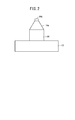
- FIG. 2 is a schematic view of the work 12 and the work holder 14 holding the work 12.
- a work holder 14 holding the work 12 is mounted on the spindle 16 of the cutting machine 10.
- the work holder 14 has a tapered surface 14a and a pull bolt 14b similar to the collet holder.
- the first tool 20 is mounted on the collet chuck 24 installed on the table 18 of the cutting machine 10.
- the collet chuck 24 is formed with a tapered hole having the same shape as the tapered hole of the spindle 16.
- the collet chuck 24 can rotate the first tool 20 and the like mounted by a motor (not shown), but can also fix the first tool 20 and the like so as not to rotate.
- the first tool 20 is, for example, a cutting tool, a drill, or the like, and is a roughing tool.
- the first tool 20 is held in a collet holder (not shown).
- the collet chuck 24 corresponds to the jig of the present invention.
- the second tool 21 is installed on the table 18 of the cutting machine 10. Unlike the first tool 20, the second tool 21 is directly fixed to the table 18.
- the second tool 21 is, for example, a cutting tool, a drill, or the like, and is a finishing tool.
- FIG. 3 is a schematic view showing a state in which the first processing of the work 12 is performed.
- the work 12 is rotated and rough machining is performed by the first tool 20 installed on the table 18.
- the collet chuck 24 fixes the first tool 20 in a non-rotatable manner.
- the finishing process is performed by the second tool 21 installed on the table 18.
- the finishing is performed by the second tool 21 installed on the table 18 while the work 12 is rotated.
- the first processing for example, lathe processing, boring processing, thread cutting processing, drilling processing and the like are performed.
- the second tool 21 of the finishing tool may be attached to the collet chuck 24, and the first tool 20 of the roughing tool may be directly fixed to the table 18.
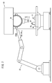
- FIG. 4 is a schematic view showing a state in which the work holder 14 is attached to the main shaft 16 and the work holder 14 is removed from the main shaft 16.
- the work holder 14 is attached to the main shaft 16 and the work holder 14 is removed from the main shaft 16 by a robot 22 provided outside the cutting machine 10 as shown in FIG.
- the work holder 14 may be attached to the main shaft 16 and the work holder 14 may be removed from the main shaft 16 by an operator.
- the installation of the collet chuck 24 on the table 18 and the removal of the collet chuck 24 from the table 18 may be performed by the robot 22 or by a worker.
- the attachment of the first tool 20 to the collet chuck 24 and the removal of the first tool 20 from the collet chuck 24 may be performed by the robot 22 or by an operator.
- the installation of the second tool 21 on the table 18 and the removal of the second tool 21 from the table 18 may also be performed by the robot 22 or by an operator.
- the robot 22 corresponds to the switching device of the present invention.
- the robot 22 of the present embodiment is an articulated robot, but it does not have to be limited to an articulated robot such as a SCARA robot. Instead of the robot 22, a device dedicated to attaching the work holder 14 or the like to the spindle 16 and removing the work holder 14 or the like from the spindle 16 may be used.
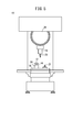
- FIG. 5 is a schematic view showing a state in which the second processing of the work 12 is performed.
- the third tool 23 is mounted on the spindle 16 of the cutting machine 10.
- the third tool 23 is, for example, a milling cutter, an end mill, or the like.
- the third tool 23 is held in a collet holder (not shown).
- a work holder 14 holding the work 12 is attached to a collet chuck 24 installed on the table 18 of the cutting machine 10.
- the second tool 21 is installed on the table 18 of the cutting machine 10, but the second tool 21 may be removed.
- the third tool 23 is rotated to machine the work 12 installed on the table 18.
- the collet chuck 24 fixes the work holder 14 so as not to rotate.
- milling processing, end mill processing, and the like are performed.
- a fourth tool (not shown) may be installed on the table 18, the work 12 may be rotated, and the work 12 may be machined by the fourth tool.
- the second processing for example, lathe processing, boring processing, thread cutting processing, drilling processing, and the like are performed.
- the attachment of the third tool 23 to the spindle 16 and the removal of the third tool 23 from the spindle 16 may be performed by a robot 22 provided outside the cutting machine 10, or may be performed by an operator. You may.
- the attachment of the work holder 14 to the collet chuck 24 and the removal of the work holder 14 from the collet chuck 24 may be performed by the robot 22 or by an operator.
- FIG. 6 is a flowchart showing the flow of processing of the work 12. The flow of processing shown in this flowchart is an example, and the processing must not be performed in this flow.
- step S1 the robot 22 installs the collet chuck 24 on the table 18 and proceeds to step S2.
- step S2 the robot 22 attaches the first tool 20 to the collet chuck 24 and proceeds to step S3.
- step S3 the robot 22 installs the second tool 21 on the table 18 and proceeds to step S4.
- step S4 the robot 22 attaches the work holder 14 to the spindle 16 and proceeds to step S5.
- the work 12 is held in the work holder 14.
- step S5 the cutting machine 10 performs the first processing and shifts to step S6.
- step S6 the robot 22 removes the work holder 14 from the spindle 16 and proceeds to step S7.
- step S7 if there is a work 12 to be processed first, the process returns to step S4, and if there is no work 12 to be processed first, the process proceeds to step S8.
- step S8 if there is a work 12 to be processed, the process proceeds to step S9, and if there is no work 12 to be processed, the processing is terminated.
- step S9 the robot 22 attaches the third tool 23 to the spindle 16 and proceeds to step S10.
- step S10 the robot 22 attaches the work holder 14 to the collet chuck 24 and proceeds to step S11.
- step S11 the cutting machine 10 performs the second processing and shifts to step S12.
- step S12 the robot 22 removes the work holder 14 from the collet chuck 24 and returns to step S8.
- the cutting machine 10 usually mounts a tool on the spindle 16 and cuts the work 12 while rotating the tool.
- a tool is pressed against a rotating work 12 such as lathe machining by the cutting machine 10
- the cutting machine 10 is used to fix the tool mounted on the spindle 16 so as not to rotate. It had to be remodeled, and there was a problem of high cost.
- the work holder 14 holding the work 12 is attached to the spindle 16 of the cutting machine 10, the spindle 16 is rotated, and the first tool 20 or the second tool 20 attached to the table 18 side is attached.
- the work 12 is machined by the tool 21.
- the work holder 14 is removed from the spindle 16 by the robot 22 installed outside the cutting machine 10. As a result, the work holder 14 is automatically removed from the spindle 16.
- the work holder 14 is removed from the spindle 16 after the first machining is completed, the work holder 14 is mounted on the collet chuck 24 installed on the table 18, and the third tool mounted on the spindle 16.
- the work 12 is processed by 23. This makes it possible to increase the types of processing that can be performed by one cutting machine 10.
- the work holder 14 is attached to the spindle 16 by the robot 22 installed outside the cutting machine 10. As a result, the work holder 14 is automatically attached to the spindle 16.
- the first tool 20 is attached to the collet chuck 24 installed on the table 18.
- the collet chuck 24 needs to be modified or the like.
- the cost of remodeling the collet chuck 24 can be reduced as compared with the cost of remodeling the cutting machine 10 for fixing the first tool 20 mounted on the spindle 16 of the cutting machine 10 so as not to rotate.
- a common collet chuck 24 can be used in the first processing and the second processing. Therefore, when shifting from the first processing to the second processing, the time for installing the collet chuck 24 can be saved. Further, when shifting from the first machining to the second machining, the setup of the work 12 is completed only by mounting the work holder 14 mounted on the spindle 16 on the collet chuck 24, so that the setup time can be shortened. Can be done.
- FIG. 7 is a schematic view showing a state in which the work holder 14 is filled in the turret 26 and the work holder 14 is removed from the turret 26.
- the work holder 14 is attached to the main shaft 16 and the work holder 14 is removed from the main shaft 16 by the turret 26 of the cutting machine 10.
- the filling of the work holder 14 in the turret 26 and the removal of the work holder 14 from the turret 26 are performed by a robot 22 provided outside the cutting machine 10.
- the filling of the work holder 14 in the turret 26 and the removal of the work holder 14 from the turret 26 may be performed by an operator.
- the turret 26 corresponds to the exchanger of the present invention.
- the robot 22 of the present embodiment is an articulated robot, but it does not have to be limited to an articulated robot such as a SCARA robot. Instead of the robot 22, a device dedicated to filling the turret 26 of the work holder 14 and removing the work holder 14 from the turret 26 may be used.
- FIG 8 and 9 are flowcharts showing the flow of processing of the work 12.
- the flow of processing shown in this flowchart is an example, and the processing must not be performed in this flow.
- step S21 the robot 22 fills the turret 26 with the work holder 14, and proceeds to step S22.
- step S22 the robot 22 installs the collet chuck 24 on the table 18 and proceeds to step S23.
- step S23 the robot 22 attaches the first tool 20 to the collet chuck 24 and proceeds to step S24.
- step S24 the robot 22 installs the second tool 21 on the table 18 and proceeds to step S25.
- step S25 the turret 26 attaches the work holder 14 to the spindle 16 and proceeds to step S26.
- step S26 the cutting machine 10 performs the first processing and shifts to step S27.
- step S27 the turret 26 removes the work holder 14 from the spindle 16 and proceeds to step S28.
- step S28 if there is a work 12 to be processed first, the process returns to step S25, and if there is no work 12 to be processed first, the process proceeds to step S29.
- step S29 the robot 22 removes the work holder 14 from the turret 26 and proceeds to step S30.
- step S30 if there is a work 12 to be subjected to the second machining, the process proceeds to step S31, and if there is no work 12 to be subjected to the second machining, the machining process is terminated.
- step S31 the robot 22 fills the turret 26 with the third tool 23 and proceeds to step S32.
- step S32 the turret 26 attaches the third tool 23 to the spindle 16 and proceeds to step S33.
- step S33 the robot 22 attaches the work holder 14 to the collet chuck 24 and proceeds to step S34.
- step S34 the cutting machine 10 performs the second processing and shifts to step S35.
- step S35 the robot 22 removes the work holder 14 from the collet chuck 24 and proceeds to step S36.
- step S36 if there is a work 12 to be subjected to the second machining, the process returns to step S33, and if there is no work 12 to be subjected to the second machining, the machining process is terminated.
- the robot 22 provided outside the cutting machine 10 fills the turret 26 of the cutting machine 10 with the work holder 14, and the turret 26 mounts the work holder 14 on the spindle 16. As a result, the work holder 14 is automatically attached to the spindle 16.
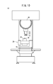
- FIG. 10 is a schematic view showing a state in which the first processing of the work 12 is performed.
- FIG. 11 is a schematic view showing how the work 12 is subjected to the second processing.
- the collet chuck 24 is provided on the additional shaft 28 installed on the table 18.
- the additional shaft 28 can rotate the collet chuck 24 around a plurality of different shafts.
- collet chuck 24 is provided on the additional shaft 28.
- the collet chuck 24 can be tilted by the additional shaft 28, and various machining can be performed on the work 12.
- the first mounting step of mounting the work holder (14) holding the work on the spindle (16) of the machine tool (10) and the rotation of the spindle are described. It has a first machining step in which the workpiece is machined by a tool (20) installed on a table (18) of a machine tool.
- the work processing method may include a removal step of removing the work holder from the spindle by an exchange device (22) installed outside the machine tool after the completion of the first processing step.
- the second mounting step of mounting the work holder on the jig (24) installed on the table, the tool mounted on the spindle, or the tool after the completion of the removal step, the second mounting step of mounting the work holder on the jig (24) installed on the table, the tool mounted on the spindle, or the tool.
- a second machining step of machining the work by the tool installed on the table may be provided.
- the work holder in the first mounting step, may be mounted on the spindle by an exchange device provided outside the machine tool.
- a filling step in which the work holder is filled in the changer (26) of the machine tool by an exchange device provided outside the machine tool before the first mounting step.
- the work holder may be mounted on the spindle by the exchanger in the first mounting step.
Abstract
L'invention porte sur un procédé d'usinage pour une pièce à travailler (12) qui est mise en rotation dans une machine-outil (10) ayant une broche principale (16), dans lequel la modification de la machine-outil (10) n'est pas nécessaire lors de l'usinage de la pièce à travailler (12). Le procédé d'usinage de la pièce à usiner (12) comprend : une première étape de montage dans laquelle un porte-pièce à travailler (14) qui porte la pièce à travailler (12) est monté sur la broche principale (16) de la machine-outil (10) ; et une première étape d'usinage dans laquelle la broche principale (16) est mise en rotation et la pièce à travailler (12) est usinée par un premier outil (20) installé sur une table (18) de la machine-outil (10).
Priority Applications (4)
| Application Number | Priority Date | Filing Date | Title |
|---|---|---|---|
| JP2022515370A JPWO2021210532A1 (fr) | 2020-04-16 | 2021-04-12 | |
| US17/918,376 US20230134626A1 (en) | 2020-04-16 | 2021-04-12 | Machining method for workpiece |
| DE112021001703.9T DE112021001703T5 (de) | 2020-04-16 | 2021-04-12 | Bearbeitungsverfahren eines Werkstücks |
| CN202180028327.8A CN115461176A (zh) | 2020-04-16 | 2021-04-12 | 工件的加工方法 |
Applications Claiming Priority (2)
| Application Number | Priority Date | Filing Date | Title |
|---|---|---|---|
| JP2020-073480 | 2020-04-16 | ||
| JP2020073480 | 2020-04-16 |
Publications (1)
| Publication Number | Publication Date |
|---|---|
| WO2021210532A1 true WO2021210532A1 (fr) | 2021-10-21 |
Family
ID=78083797
Family Applications (1)
| Application Number | Title | Priority Date | Filing Date |
|---|---|---|---|
| PCT/JP2021/015163 WO2021210532A1 (fr) | 2020-04-16 | 2021-04-12 | Procédé d'usinage pour pièce à travailler |
Country Status (5)
| Country | Link |
|---|---|
| US (1) | US20230134626A1 (fr) |
| JP (1) | JPWO2021210532A1 (fr) |
| CN (1) | CN115461176A (fr) |
| DE (1) | DE112021001703T5 (fr) |
| WO (1) | WO2021210532A1 (fr) |
Citations (5)
| Publication number | Priority date | Publication date | Assignee | Title |
|---|---|---|---|---|
| JPS58202744A (ja) * | 1982-03-10 | 1983-11-26 | レニシヨウ パブリツク リミテツド カンパニ− | 工作機械 |
| JPH0592302A (ja) * | 1991-09-27 | 1993-04-16 | Olympus Optical Co Ltd | 複合工作機械 |
| JP2001277064A (ja) * | 2000-03-30 | 2001-10-09 | Nissan Motor Co Ltd | 加工システム |
| JP2016175152A (ja) * | 2015-03-20 | 2016-10-06 | Dmg森精機株式会社 | ワークの加工方法 |
| WO2019053900A1 (fr) * | 2017-09-15 | 2019-03-21 | 株式会社牧野フライス製作所 | Système de machine-outil |
Family Cites Families (1)
| Publication number | Priority date | Publication date | Assignee | Title |
|---|---|---|---|---|
| JP5853814B2 (ja) | 2012-03-27 | 2016-02-09 | ブラザー工業株式会社 | 工作機械 |
-
2021
- 2021-04-12 US US17/918,376 patent/US20230134626A1/en active Pending
- 2021-04-12 WO PCT/JP2021/015163 patent/WO2021210532A1/fr active Application Filing
- 2021-04-12 JP JP2022515370A patent/JPWO2021210532A1/ja active Pending
- 2021-04-12 CN CN202180028327.8A patent/CN115461176A/zh not_active Withdrawn
- 2021-04-12 DE DE112021001703.9T patent/DE112021001703T5/de active Pending
Patent Citations (5)
| Publication number | Priority date | Publication date | Assignee | Title |
|---|---|---|---|---|
| JPS58202744A (ja) * | 1982-03-10 | 1983-11-26 | レニシヨウ パブリツク リミテツド カンパニ− | 工作機械 |
| JPH0592302A (ja) * | 1991-09-27 | 1993-04-16 | Olympus Optical Co Ltd | 複合工作機械 |
| JP2001277064A (ja) * | 2000-03-30 | 2001-10-09 | Nissan Motor Co Ltd | 加工システム |
| JP2016175152A (ja) * | 2015-03-20 | 2016-10-06 | Dmg森精機株式会社 | ワークの加工方法 |
| WO2019053900A1 (fr) * | 2017-09-15 | 2019-03-21 | 株式会社牧野フライス製作所 | Système de machine-outil |
Also Published As
| Publication number | Publication date |
|---|---|
| CN115461176A (zh) | 2022-12-09 |
| JPWO2021210532A1 (fr) | 2021-10-21 |
| DE112021001703T5 (de) | 2023-01-12 |
| US20230134626A1 (en) | 2023-05-04 |
Similar Documents
| Publication | Publication Date | Title |
|---|---|---|
| KR101676885B1 (ko) | 머시닝 센터용 유니버셜 툴 마운팅 시스템 | |
| EP2353757B1 (fr) | Procédé d'alésage d'une pièce par une machine-outil d'usinage à 5 axes à double boîtier | |
| JPS63229233A (ja) | 工作機械 | |
| JP2009502521A (ja) | 傘歯車のソフト機械加工用万能機械と対応する方法 | |
| JPH058136A (ja) | 複数の加工要素を持つ加工システム | |
| KR101368761B1 (ko) | 플랜지 요크의 가공방법 | |
| CN104781037A (zh) | 十字轴在车床上的加工过程 | |
| JP2008023611A (ja) | 複合nc旋盤 | |
| WO2021210532A1 (fr) | Procédé d'usinage pour pièce à travailler | |
| CN107486681B (zh) | 一种细长轴类零件加工工艺 | |
| JP2007075922A (ja) | 複合旋盤 | |
| KR101016580B1 (ko) | 공구 매거진 | |
| JP2008006570A (ja) | 砥石車の着脱構造 | |
| JP5474266B1 (ja) | 工作機械の内径旋削アタッチメント | |
| KR100938081B1 (ko) | 매거진과 atc도어가 일체화된 구조를 갖는 엄브렐라타입 자동공구교환장치 | |
| JPH074681B2 (ja) | Nc施盤 | |
| JP2002263909A (ja) | 工作機械 | |
| JP2012161904A (ja) | 複合工具、加工方法および工作機械 | |
| JPH1015703A (ja) | 多機能旋盤 | |
| JP2001191253A (ja) | 汎用加工治具及びこれを用いた加工方法 | |
| JP2003311501A (ja) | 2主軸対向旋盤の対向ワークの同時加工方法 | |
| JP2604616Y2 (ja) | 3台のz軸台を有する自動多面加工機 | |
| US5448820A (en) | Method of manufacturing flanged shafts | |
| KR200237531Y1 (ko) | 에어콘 콤프레셔용 샤프트 복합 가공장치 | |
| JPH081403A (ja) | Nc装置付き工作機械によるネジ端部バリ取り方法 |
Legal Events
| Date | Code | Title | Description |
|---|---|---|---|
| 121 | Ep: the epo has been informed by wipo that ep was designated in this application |
Ref document number: 21789228 Country of ref document: EP Kind code of ref document: A1 |
|
| ENP | Entry into the national phase |
Ref document number: 2022515370 Country of ref document: JP Kind code of ref document: A |
|
| 122 | Ep: pct application non-entry in european phase |
Ref document number: 21789228 Country of ref document: EP Kind code of ref document: A1 |