WO2021210532A1 - Machining method for workpiece - Google Patents
Machining method for workpiece Download PDFInfo
- Publication number
- WO2021210532A1 WO2021210532A1 PCT/JP2021/015163 JP2021015163W WO2021210532A1 WO 2021210532 A1 WO2021210532 A1 WO 2021210532A1 JP 2021015163 W JP2021015163 W JP 2021015163W WO 2021210532 A1 WO2021210532 A1 WO 2021210532A1
- Authority
- WO
- WIPO (PCT)
- Prior art keywords
- work
- tool
- spindle
- processing
- machining
- Prior art date
Links
Images


Classifications
-
- B—PERFORMING OPERATIONS; TRANSPORTING
- B23—MACHINE TOOLS; METAL-WORKING NOT OTHERWISE PROVIDED FOR
- B23P—METAL-WORKING NOT OTHERWISE PROVIDED FOR; COMBINED OPERATIONS; UNIVERSAL MACHINE TOOLS
- B23P23/00—Machines or arrangements of machines for performing specified combinations of different metal-working operations not covered by a single other subclass
- B23P23/02—Machine tools for performing different machining operations
-
- B—PERFORMING OPERATIONS; TRANSPORTING
- B23—MACHINE TOOLS; METAL-WORKING NOT OTHERWISE PROVIDED FOR
- B23B—TURNING; BORING
- B23B3/00—General-purpose turning-machines or devices, e.g. centre lathes with feed rod and lead screw; Sets of turning-machines
- B23B3/16—Turret lathes for turning individually-chucked workpieces
- B23B3/161—Turret lathes for turning individually-chucked workpieces lathe with one toolslide carrying one turret head
- B23B3/162—Arrangements for performing other machining operations, e.g. milling, drilling
-
- B—PERFORMING OPERATIONS; TRANSPORTING
- B23—MACHINE TOOLS; METAL-WORKING NOT OTHERWISE PROVIDED FOR
- B23B—TURNING; BORING
- B23B1/00—Methods for turning or working essentially requiring the use of turning-machines; Use of auxiliary equipment in connection with such methods
-
- B—PERFORMING OPERATIONS; TRANSPORTING
- B23—MACHINE TOOLS; METAL-WORKING NOT OTHERWISE PROVIDED FOR
- B23B—TURNING; BORING
- B23B11/00—Automatic or semi-automatic turning-machines incorporating equipment for performing other working procedures, e.g. slotting, milling, rolling
-
- B—PERFORMING OPERATIONS; TRANSPORTING
- B23—MACHINE TOOLS; METAL-WORKING NOT OTHERWISE PROVIDED FOR
- B23B—TURNING; BORING
- B23B3/00—General-purpose turning-machines or devices, e.g. centre lathes with feed rod and lead screw; Sets of turning-machines
- B23B3/06—Turning-machines or devices characterised only by the special arrangement of constructional units
- B23B3/065—Arrangements for performing other machining operations, e.g. milling, drilling
-
- B—PERFORMING OPERATIONS; TRANSPORTING
- B23—MACHINE TOOLS; METAL-WORKING NOT OTHERWISE PROVIDED FOR
- B23B—TURNING; BORING
- B23B31/00—Chucks; Expansion mandrels; Adaptations thereof for remote control
- B23B31/02—Chucks
- B23B31/10—Chucks characterised by the retaining or gripping devices or their immediate operating means
- B23B31/12—Chucks with simultaneously-acting jaws, whether or not also individually adjustable
- B23B31/20—Longitudinally-split sleeves, e.g. collet chucks
Abstract
Provided is a machining method for a workpiece (12) that is rotated in a machine tool (10) having a main spindle (16), in which modification of the machine tool (10) is not necessary when machining the workpiece (12). The machining method for the workpiece (12) comprises: a first mounting step in which a workpiece holder (14) that is holding the workpiece (12) is mounted onto the main spindle (16) of the machine tool (10); and a first machining step in which the main spindle (16) is rotated and the workpiece (12) is machined by a first tool (20) installed on a table (18) of the machine tool (10).
Description
本発明は、ワークの加工方法に関する。
The present invention relates to a work processing method.
従来から、主軸に転削工具を装着して、転削工具を回転させてワークの加工を行う転削加工と、主軸に旋削工具を装着して、ワークを回転させてワークの加工を行う旋削加工の両方を行うことができる工作機械がある(例えば、特開2013-202713号公報)。
Conventionally, turning is performed by attaching a turning tool to the spindle and rotating the turning tool to process the workpiece, and turning by attaching a turning tool to the spindle and rotating the workpiece to process the workpiece. There are machine tools capable of performing both processing (for example, Japanese Patent Application Laid-Open No. 2013-202713).
上記の技術では、主軸に装着された旋削工具によりワークの加工を行うために、工作機械の改造が必要となる問題があった。
With the above technology, there was a problem that the machine tool had to be modified in order to process the workpiece with the turning tool mounted on the spindle.
本発明は、上記の問題を解決するためになされたものであり、主軸を有する工作機械において回転させたワークの加工を行うにあたり、工作機械の改造を必要としないワークの加工方法を提供することを目的とする。
The present invention has been made to solve the above problems, and provides a method for machining a workpiece that does not require modification of the machine tool when machining a rotated workpiece in a machine tool having a spindle. With the goal.
本発明の態様は、ワークの加工方法であって、工作機械の主軸にワークを保持しているワークホルダを装着する第1装着ステップと、前記主軸を回転させて、前記工作機械のテーブルに設置された工具によって前記ワークの加工を行う第1加工ステップと、を有する。
An aspect of the present invention is a method of machining a work, in which a first mounting step of mounting a work holder holding a work on a spindle of a machine tool and a rotation of the spindle are installed on a table of the machine tool. It has a first machining step in which the workpiece is machined by the tool.
本発明により、主軸を有する工作機械において回転させたワークの加工を行うにあたり、工作機械の改造を必要としない。
According to the present invention, it is not necessary to modify the machine tool when processing the rotated work in the machine tool having a spindle.
〔第1実施形態〕
図1は切削加工機10の模式図である。切削加工機10は、第1加工と第2加工とを行う。第1加工とは、ワーク12が切削加工機10の主軸16側に取り付けられて行われる加工を示す。第2加工とは、ワーク12が切削加工機10のテーブル18側に取り付けられて行われる加工を示す。切削加工機10は、本発明の工作機械に相当する。 [First Embodiment]
FIG. 1 is a schematic view of thecutting machine 10. The cutting machine 10 performs the first processing and the second processing. The first machining refers to machining performed by attaching the work 12 to the spindle 16 side of the cutting machine 10. The second processing refers to processing performed by attaching the work 12 to the table 18 side of the cutting machine 10. The cutting machine 10 corresponds to the machine tool of the present invention.
図1は切削加工機10の模式図である。切削加工機10は、第1加工と第2加工とを行う。第1加工とは、ワーク12が切削加工機10の主軸16側に取り付けられて行われる加工を示す。第2加工とは、ワーク12が切削加工機10のテーブル18側に取り付けられて行われる加工を示す。切削加工機10は、本発明の工作機械に相当する。 [First Embodiment]
FIG. 1 is a schematic view of the
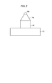
図2はワーク12及びワーク12を保持するワークホルダ14の模式図である。切削加工機10の主軸16にワーク12を保持しているワークホルダ14が装着されている。ワークホルダ14は、図2に示すように、コレットホルダ同様のテーパ面14a及びプルボルト14bを有している。
FIG. 2 is a schematic view of the work 12 and the work holder 14 holding the work 12. A work holder 14 holding the work 12 is mounted on the spindle 16 of the cutting machine 10. As shown in FIG. 2, the work holder 14 has a tapered surface 14a and a pull bolt 14b similar to the collet holder.
切削加工機10のテーブル18に設置されたコレットチャック24に、第1工具20が装着されている。コレットチャック24は、主軸16のテーパ孔と同じ形状のテーパ孔が形成されている。コレットチャック24は図示しないモータによって装着された第1工具20等を回転させることもできるが、第1工具20等を回転不能に固定することもできる。なお、第1工具20は、例えば、バイト、ドリル等であって、荒加工用工具である。第1工具20は、図示しないコレットホルダに保持されている。コレットチャック24は、本発明の治具に相当する。
The first tool 20 is mounted on the collet chuck 24 installed on the table 18 of the cutting machine 10. The collet chuck 24 is formed with a tapered hole having the same shape as the tapered hole of the spindle 16. The collet chuck 24 can rotate the first tool 20 and the like mounted by a motor (not shown), but can also fix the first tool 20 and the like so as not to rotate. The first tool 20 is, for example, a cutting tool, a drill, or the like, and is a roughing tool. The first tool 20 is held in a collet holder (not shown). The collet chuck 24 corresponds to the jig of the present invention.
切削加工機10のテーブル18に第2工具21が設置されている。第2工具21は、第1工具20と異なり、直接テーブル18に固定されている。第2工具21は、例えば、バイト、ドリル等であって、仕上げ加工用工具である。
The second tool 21 is installed on the table 18 of the cutting machine 10. Unlike the first tool 20, the second tool 21 is directly fixed to the table 18. The second tool 21 is, for example, a cutting tool, a drill, or the like, and is a finishing tool.
図3はワーク12の第1加工を行う様子を示す模式図である。ワーク12を回転させて、テーブル18に設置された第1工具20により荒加工が行われる。このとき、コレットチャック24は、第1工具20を回転不能に固定する。その後、ワーク12を回転させたまま、テーブル18に設置された第2工具21により仕上げ加工を行う。荒加工後、ワーク12を回転させたまま、テーブル18に設置された第2工具21により仕上げ加工が行われる。第1加工では、例えば、旋盤加工、中ぐり加工、ねじ切り加工、穴あけ加工等が行われる。
FIG. 3 is a schematic view showing a state in which the first processing of the work 12 is performed. The work 12 is rotated and rough machining is performed by the first tool 20 installed on the table 18. At this time, the collet chuck 24 fixes the first tool 20 in a non-rotatable manner. After that, while the work 12 is rotated, the finishing process is performed by the second tool 21 installed on the table 18. After the roughing, the finishing is performed by the second tool 21 installed on the table 18 while the work 12 is rotated. In the first processing, for example, lathe processing, boring processing, thread cutting processing, drilling processing and the like are performed.
なお、仕上げ加工用工具の第2工具21がコレットチャック24に装着され、荒加工用工具の第1工具20が直接テーブル18に固定されていてもよい。
The second tool 21 of the finishing tool may be attached to the collet chuck 24, and the first tool 20 of the roughing tool may be directly fixed to the table 18.
図4は主軸16へのワークホルダ14の装着、及び、主軸16からのワークホルダ14の取り外しの様子を示す模式図である。主軸16へのワークホルダ14の装着、及び、主軸16からのワークホルダ14の取り外しは、図4に示すように切削加工機10の外部に設けられたロボット22により行われる。主軸16へのワークホルダ14の装着、及び、主軸16からのワークホルダ14の取り外しは、作業員によって行われてもよい。
FIG. 4 is a schematic view showing a state in which the work holder 14 is attached to the main shaft 16 and the work holder 14 is removed from the main shaft 16. The work holder 14 is attached to the main shaft 16 and the work holder 14 is removed from the main shaft 16 by a robot 22 provided outside the cutting machine 10 as shown in FIG. The work holder 14 may be attached to the main shaft 16 and the work holder 14 may be removed from the main shaft 16 by an operator.
テーブル18へのコレットチャック24の設置、及び、テーブル18からのコレットチャック24の取り外しはロボット22により行われてもよいし、作業員によって行われてもよい。コレットチャック24への第1工具20の装着、及び、コレットチャック24からの第1工具20の取り外しはロボット22により行われてもよいし、作業員によって行われてもよい。テーブル18への第2工具21の設置、及び、テーブル18からの第2工具21の取り外しもロボット22により行われてもよいし、作業員によって行われてもよい。ロボット22は、本発明の交換装置に相当する。
The installation of the collet chuck 24 on the table 18 and the removal of the collet chuck 24 from the table 18 may be performed by the robot 22 or by a worker. The attachment of the first tool 20 to the collet chuck 24 and the removal of the first tool 20 from the collet chuck 24 may be performed by the robot 22 or by an operator. The installation of the second tool 21 on the table 18 and the removal of the second tool 21 from the table 18 may also be performed by the robot 22 or by an operator. The robot 22 corresponds to the switching device of the present invention.
本実施形態のロボット22は多関節ロボットであるが、スカラロボット等、多関節ロボットに限らなくてもよい。ロボット22に代えて、ワークホルダ14等の主軸16への装着、及び、主軸16からのワークホルダ14等の取り外し専用の装置が用いられてもよい。
The robot 22 of the present embodiment is an articulated robot, but it does not have to be limited to an articulated robot such as a SCARA robot. Instead of the robot 22, a device dedicated to attaching the work holder 14 or the like to the spindle 16 and removing the work holder 14 or the like from the spindle 16 may be used.
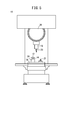
図5はワーク12の第2加工を行う様子を示す模式図である。第2加工では、切削加工機10の主軸16に第3工具23が装着されている。第3工具23は、例えば、フライス、エンドミル等である。第3工具23は、図示しないコレットホルダに保持されている。
FIG. 5 is a schematic view showing a state in which the second processing of the work 12 is performed. In the second machining, the third tool 23 is mounted on the spindle 16 of the cutting machine 10. The third tool 23 is, for example, a milling cutter, an end mill, or the like. The third tool 23 is held in a collet holder (not shown).
切削加工機10のテーブル18に設置されたコレットチャック24に、ワーク12を保持しているワークホルダ14が装着されている。
A work holder 14 holding the work 12 is attached to a collet chuck 24 installed on the table 18 of the cutting machine 10.
図5では、切削加工機10のテーブル18に第2工具21が設置されているが、第2工具21は取り外されていてもよい。
In FIG. 5, the second tool 21 is installed on the table 18 of the cutting machine 10, but the second tool 21 may be removed.
第2加工では、第3工具23を回転させて、テーブル18に設置されたワーク12の加工が行われる。このとき、コレットチャック24は、ワークホルダ14を回転不能に固定する。第2加工では、例えば、フライス加工、エンドミル加工等が行われる。
In the second machining, the third tool 23 is rotated to machine the work 12 installed on the table 18. At this time, the collet chuck 24 fixes the work holder 14 so as not to rotate. In the second processing, for example, milling processing, end mill processing, and the like are performed.
また、第2加工では、図示しない第4工具がテーブル18に設置され、ワーク12を回転させて、第4工具によりワーク12の加工が行われてもよい。この場合、第2加工では、例えば、旋盤加工、中ぐり加工、ねじ切り加工、穴あけ加工等が行われる。
Further, in the second machining, a fourth tool (not shown) may be installed on the table 18, the work 12 may be rotated, and the work 12 may be machined by the fourth tool. In this case, in the second processing, for example, lathe processing, boring processing, thread cutting processing, drilling processing, and the like are performed.
主軸16への第3工具23の装着、及び、主軸16からの第3工具23の取り外しは、切削加工機10の外部に設けられたロボット22により行われてもよいし、作業員によって行われてもよい。コレットチャック24へのワークホルダ14の装着、及び、コレットチャック24からのワークホルダ14の取り外しはロボット22により行われてもよいし、作業員によって行われてもよい。
The attachment of the third tool 23 to the spindle 16 and the removal of the third tool 23 from the spindle 16 may be performed by a robot 22 provided outside the cutting machine 10, or may be performed by an operator. You may. The attachment of the work holder 14 to the collet chuck 24 and the removal of the work holder 14 from the collet chuck 24 may be performed by the robot 22 or by an operator.
図6はワーク12の加工処理の流れを示すフローチャートである。このフローチャートで示す加工処理の流れは一例であって、この流れで加工処理が行われなければならないものではない。
FIG. 6 is a flowchart showing the flow of processing of the work 12. The flow of processing shown in this flowchart is an example, and the processing must not be performed in this flow.
ステップS1において、ロボット22はテーブル18にコレットチャック24を設置して、ステップS2へ移行する。
In step S1, the robot 22 installs the collet chuck 24 on the table 18 and proceeds to step S2.
ステップS2において、ロボット22はコレットチャック24に第1工具20を装着して、ステップS3へ移行する。
In step S2, the robot 22 attaches the first tool 20 to the collet chuck 24 and proceeds to step S3.
ステップS3において、ロボット22はテーブル18に第2工具21を設置して、ステップS4へ移行する。
In step S3, the robot 22 installs the second tool 21 on the table 18 and proceeds to step S4.
ステップS4において、ロボット22は主軸16にワークホルダ14を装着して、ステップS5へ移行する。ワークホルダ14には、ワーク12が保持されている。
In step S4, the robot 22 attaches the work holder 14 to the spindle 16 and proceeds to step S5. The work 12 is held in the work holder 14.
ステップS5において、切削加工機10は第1加工を行って、ステップS6へ移行する。
In step S5, the cutting machine 10 performs the first processing and shifts to step S6.
ステップS6において、ロボット22は主軸16からワークホルダ14を取り外して、ステップS7へ移行する。
In step S6, the robot 22 removes the work holder 14 from the spindle 16 and proceeds to step S7.
ステップS7において、第1加工を行うワーク12がある場合にはステップS4に戻り、第1加工を行うワーク12がない場合にはステップS8へ移行する。
In step S7, if there is a work 12 to be processed first, the process returns to step S4, and if there is no work 12 to be processed first, the process proceeds to step S8.
ステップS8において、第2加工を行うワーク12がある場合にはステップS9へ移行し、第2加工を行うワーク12がない場合には加工処理を終了する。
In step S8, if there is a work 12 to be processed, the process proceeds to step S9, and if there is no work 12 to be processed, the processing is terminated.
ステップS9において、ロボット22は主軸16に第3工具23を装着して、ステップS10へ移行する。
In step S9, the robot 22 attaches the third tool 23 to the spindle 16 and proceeds to step S10.
ステップS10において、ロボット22はコレットチャック24にワークホルダ14を装着して、ステップS11へ移行する。
In step S10, the robot 22 attaches the work holder 14 to the collet chuck 24 and proceeds to step S11.
ステップS11において、切削加工機10は第2加工を行って、ステップS12へ移行する。
In step S11, the cutting machine 10 performs the second processing and shifts to step S12.
ステップS12において、ロボット22はコレットチャック24からワークホルダ14を取り外して、ステップS8へ戻る。
In step S12, the robot 22 removes the work holder 14 from the collet chuck 24 and returns to step S8.
[作用効果]
切削加工機10は、通常、主軸16に工具を装着し、工具を回転させながらワーク12の切削加工を行う。この切削加工機10によって、旋盤加工等のように回転するワーク12に工具を押し当てて加工しようとする場合、主軸16に装着された工具を回転不能に固定するために、切削加工機10を改造する必要があり、高コスト化する問題があった。 [Action effect]
The cuttingmachine 10 usually mounts a tool on the spindle 16 and cuts the work 12 while rotating the tool. When a tool is pressed against a rotating work 12 such as lathe machining by the cutting machine 10, the cutting machine 10 is used to fix the tool mounted on the spindle 16 so as not to rotate. It had to be remodeled, and there was a problem of high cost.
切削加工機10は、通常、主軸16に工具を装着し、工具を回転させながらワーク12の切削加工を行う。この切削加工機10によって、旋盤加工等のように回転するワーク12に工具を押し当てて加工しようとする場合、主軸16に装着された工具を回転不能に固定するために、切削加工機10を改造する必要があり、高コスト化する問題があった。 [Action effect]
The cutting
そこで、本実施形態では、切削加工機10の主軸16にワーク12を保持しているワークホルダ14を装着し、主軸16を回転させて、テーブル18側に取り付けられた第1工具20又は第2工具21によってワーク12の加工を行う。これにより、回転させたワーク12の加工を行うにあたり、切削加工機10の改造を行う必要がなく、コストを抑制することができる。
Therefore, in the present embodiment, the work holder 14 holding the work 12 is attached to the spindle 16 of the cutting machine 10, the spindle 16 is rotated, and the first tool 20 or the second tool 20 attached to the table 18 side is attached. The work 12 is machined by the tool 21. As a result, it is not necessary to modify the cutting machine 10 when processing the rotated work 12, and the cost can be suppressed.
また、本実施形態では、第1加工終了後に、切削加工機10の外部に設置されたロボット22によって主軸16からワークホルダ14が取り外される。これにより、主軸16からのワークホルダ14の取り外しが自動で行われる。
Further, in the present embodiment, after the first machining is completed, the work holder 14 is removed from the spindle 16 by the robot 22 installed outside the cutting machine 10. As a result, the work holder 14 is automatically removed from the spindle 16.
また、本実施形態では、第1加工終了後、主軸16からワークホルダ14を取り外した後に、テーブル18に設置されたコレットチャック24にワークホルダ14を装着し、主軸16に装着された第3工具23によってワーク12の加工を行う。これにより、1つの切削加工機10で行える加工の種類を増大させることができる。
Further, in the present embodiment, after the work holder 14 is removed from the spindle 16 after the first machining is completed, the work holder 14 is mounted on the collet chuck 24 installed on the table 18, and the third tool mounted on the spindle 16. The work 12 is processed by 23. This makes it possible to increase the types of processing that can be performed by one cutting machine 10.
また、本実施形態では、切削加工機10の外部に設置されたロボット22によって主軸16にワークホルダ14が装着される。これにより、主軸16へのワークホルダ14の装着が自動で行われる。
Further, in the present embodiment, the work holder 14 is attached to the spindle 16 by the robot 22 installed outside the cutting machine 10. As a result, the work holder 14 is automatically attached to the spindle 16.
また、本実施形態では、テーブル18に設置されたコレットチャック24に第1工具20が装着される。コレットチャック24が第1工具20を回転不能に固定するために、コレットチャック24に改造等が必要となる。しかし、切削加工機10の主軸16に装着された第1工具20を回転不能に固定するための切削加工機10の改造のコストに比べると、コレットチャック24の改造のコストを低減できる。
Further, in the present embodiment, the first tool 20 is attached to the collet chuck 24 installed on the table 18. In order for the collet chuck 24 to fix the first tool 20 so as not to rotate, the collet chuck 24 needs to be modified or the like. However, the cost of remodeling the collet chuck 24 can be reduced as compared with the cost of remodeling the cutting machine 10 for fixing the first tool 20 mounted on the spindle 16 of the cutting machine 10 so as not to rotate.
また、第1加工と第2加工で、共通のコレットチャック24を用いることができる。そのため、第1加工から第2加工に移行する際に、コレットチャック24の設置の時間を省くことができる。また、第1加工から第2加工に移行する際に、主軸16に装着されていたワークホルダ14をコレットチャック24に装着するだけで、ワーク12の段取りが完了するため、段取り時間を短縮することができる。
Further, a common collet chuck 24 can be used in the first processing and the second processing. Therefore, when shifting from the first processing to the second processing, the time for installing the collet chuck 24 can be saved. Further, when shifting from the first machining to the second machining, the setup of the work 12 is completed only by mounting the work holder 14 mounted on the spindle 16 on the collet chuck 24, so that the setup time can be shortened. Can be done.
〔第2実施形態〕
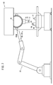
図7はタレット26へのワークホルダ14の充填、及び、タレット26からのワークホルダ14の取り外しの様子を示す模式図である。主軸16へのワークホルダ14の装着、及び、主軸16からのワークホルダ14の取り外しは、切削加工機10のタレット26により行われる。タレット26へのワークホルダ14の充填、及び、タレット26からのワークホルダ14の取り外しは、切削加工機10の外部に設けられたロボット22により行われる。タレット26へのワークホルダ14の充填、及び、タレット26からのワークホルダ14の取り外しは、作業員によって行われてもよい。タレット26は、本発明の交換器に相当する。 [Second Embodiment]
FIG. 7 is a schematic view showing a state in which thework holder 14 is filled in the turret 26 and the work holder 14 is removed from the turret 26. The work holder 14 is attached to the main shaft 16 and the work holder 14 is removed from the main shaft 16 by the turret 26 of the cutting machine 10. The filling of the work holder 14 in the turret 26 and the removal of the work holder 14 from the turret 26 are performed by a robot 22 provided outside the cutting machine 10. The filling of the work holder 14 in the turret 26 and the removal of the work holder 14 from the turret 26 may be performed by an operator. The turret 26 corresponds to the exchanger of the present invention.
図7はタレット26へのワークホルダ14の充填、及び、タレット26からのワークホルダ14の取り外しの様子を示す模式図である。主軸16へのワークホルダ14の装着、及び、主軸16からのワークホルダ14の取り外しは、切削加工機10のタレット26により行われる。タレット26へのワークホルダ14の充填、及び、タレット26からのワークホルダ14の取り外しは、切削加工機10の外部に設けられたロボット22により行われる。タレット26へのワークホルダ14の充填、及び、タレット26からのワークホルダ14の取り外しは、作業員によって行われてもよい。タレット26は、本発明の交換器に相当する。 [Second Embodiment]
FIG. 7 is a schematic view showing a state in which the
本実施形態のロボット22は多関節ロボットであるが、スカラロボット等、多関節ロボットに限らなくてもよい。ロボット22に代えて、ワークホルダ14のタレット26への充填、及び、タレット26からの取外し専用の装置が用いられてもよい。
The robot 22 of the present embodiment is an articulated robot, but it does not have to be limited to an articulated robot such as a SCARA robot. Instead of the robot 22, a device dedicated to filling the turret 26 of the work holder 14 and removing the work holder 14 from the turret 26 may be used.
図8及び図9はワーク12の加工処理の流れを示すフローチャートである。このフローチャートで示す加工処理の流れは一例であって、この流れで加工処理が行われなければならないものではない。
8 and 9 are flowcharts showing the flow of processing of the work 12. The flow of processing shown in this flowchart is an example, and the processing must not be performed in this flow.
ステップS21において、ロボット22はタレット26にワークホルダ14を充填して、ステップS22へ移行する。
In step S21, the robot 22 fills the turret 26 with the work holder 14, and proceeds to step S22.
ステップS22において、ロボット22はテーブル18にコレットチャック24を設置して、ステップS23へ移行する。
In step S22, the robot 22 installs the collet chuck 24 on the table 18 and proceeds to step S23.
ステップS23において、ロボット22はコレットチャック24に第1工具20を装着して、ステップS24へ移行する。
In step S23, the robot 22 attaches the first tool 20 to the collet chuck 24 and proceeds to step S24.
ステップS24において、ロボット22はテーブル18に第2工具21を設置して、ステップS25へ移行する。
In step S24, the robot 22 installs the second tool 21 on the table 18 and proceeds to step S25.
ステップS25において、タレット26は主軸16にワークホルダ14を装着して、ステップS26へ移行する。
In step S25, the turret 26 attaches the work holder 14 to the spindle 16 and proceeds to step S26.
ステップS26において、切削加工機10は第1加工を行って、ステップS27へ移行する。
In step S26, the cutting machine 10 performs the first processing and shifts to step S27.
ステップS27において、タレット26は主軸16からワークホルダ14を取り外して、ステップS28へ移行する。
In step S27, the turret 26 removes the work holder 14 from the spindle 16 and proceeds to step S28.
ステップS28において、第1加工を行うワーク12がある場合にはステップS25に戻り、第1加工を行うワーク12がない場合にはステップS29へ移行する。
In step S28, if there is a work 12 to be processed first, the process returns to step S25, and if there is no work 12 to be processed first, the process proceeds to step S29.
ステップS29において、ロボット22はタレット26からワークホルダ14を取り外して、ステップS30へ移行する。
In step S29, the robot 22 removes the work holder 14 from the turret 26 and proceeds to step S30.
ステップS30において、第2加工を行うワーク12がある場合にはステップS31へ移行し、第2加工を行うワーク12がない場合には加工処理を終了する。
In step S30, if there is a work 12 to be subjected to the second machining, the process proceeds to step S31, and if there is no work 12 to be subjected to the second machining, the machining process is terminated.
ステップS31において、ロボット22はタレット26に第3工具23を充填して、ステップS32へ移行する。
In step S31, the robot 22 fills the turret 26 with the third tool 23 and proceeds to step S32.
ステップS32において、タレット26は主軸16に第3工具23を装着して、ステップS33へ移行する。
In step S32, the turret 26 attaches the third tool 23 to the spindle 16 and proceeds to step S33.
ステップS33において、ロボット22はコレットチャック24にワークホルダ14を装着して、ステップS34へ移行する。
In step S33, the robot 22 attaches the work holder 14 to the collet chuck 24 and proceeds to step S34.
ステップS34において、切削加工機10は第2加工を行って、ステップS35へ移行する。
In step S34, the cutting machine 10 performs the second processing and shifts to step S35.
ステップS35において、ロボット22はコレットチャック24からワークホルダ14を取り外して、ステップS36へ移行する。
In step S35, the robot 22 removes the work holder 14 from the collet chuck 24 and proceeds to step S36.
ステップS36において、第2加工を行うワーク12がある場合にはステップS33へ戻り、第2加工を行うワーク12がない場合には加工処理を終了する。
In step S36, if there is a work 12 to be subjected to the second machining, the process returns to step S33, and if there is no work 12 to be subjected to the second machining, the machining process is terminated.
[作用効果]
本実施形態では、切削加工機10の外部に設けられたロボット22によって、切削加工機10のタレット26にワークホルダ14を充填し、タレット26が主軸16にワークホルダ14を装着する。これにより、主軸16へのワークホルダ14の装着が自動で行われる。 [Action effect]
In the present embodiment, therobot 22 provided outside the cutting machine 10 fills the turret 26 of the cutting machine 10 with the work holder 14, and the turret 26 mounts the work holder 14 on the spindle 16. As a result, the work holder 14 is automatically attached to the spindle 16.
本実施形態では、切削加工機10の外部に設けられたロボット22によって、切削加工機10のタレット26にワークホルダ14を充填し、タレット26が主軸16にワークホルダ14を装着する。これにより、主軸16へのワークホルダ14の装着が自動で行われる。 [Action effect]
In the present embodiment, the
〔第3実施形態〕
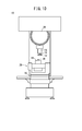
図10はワーク12の第1加工を行う様子を示す模式図である。図11はワーク12の第2加工を行う様子を示す模式図である。 [Third Embodiment]
FIG. 10 is a schematic view showing a state in which the first processing of thework 12 is performed. FIG. 11 is a schematic view showing how the work 12 is subjected to the second processing.
図10はワーク12の第1加工を行う様子を示す模式図である。図11はワーク12の第2加工を行う様子を示す模式図である。 [Third Embodiment]
FIG. 10 is a schematic view showing a state in which the first processing of the
本実施形態では、テーブル18に設置された付加軸28に、コレットチャック24が設けられている。付加軸28は、複数の異なる軸を中心にコレットチャック24を回動させることができる。
In the present embodiment, the collet chuck 24 is provided on the additional shaft 28 installed on the table 18. The additional shaft 28 can rotate the collet chuck 24 around a plurality of different shafts.
付加軸28にコレットチャック24が設けられている以外の点については、第1実施形態又は第2実施形態と同様である。
It is the same as the first embodiment or the second embodiment except that the collet chuck 24 is provided on the additional shaft 28.
[作用効果]
付加軸28によりコレットチャック24を傾けることができ、ワーク12に対して多彩な加工を行うことができる。 [Action effect]
Thecollet chuck 24 can be tilted by the additional shaft 28, and various machining can be performed on the work 12.
付加軸28によりコレットチャック24を傾けることができ、ワーク12に対して多彩な加工を行うことができる。 [Action effect]
The
〔実施形態から得られる技術的思想〕
上記実施形態から把握しうる技術的思想について、以下に記載する。 [Technical Thought Obtained from the Embodiment]
The technical ideas that can be grasped from the above embodiments are described below.
上記実施形態から把握しうる技術的思想について、以下に記載する。 [Technical Thought Obtained from the Embodiment]
The technical ideas that can be grasped from the above embodiments are described below.
ワーク(12)の加工方法であって、工作機械(10)の主軸(16)にワークを保持しているワークホルダ(14)を装着する第1装着ステップと、前記主軸を回転させて、前記工作機械のテーブル(18)に設置された工具(20)によって前記ワークの加工を行う第1加工ステップと、を有する。
In the processing method of the work (12), the first mounting step of mounting the work holder (14) holding the work on the spindle (16) of the machine tool (10) and the rotation of the spindle are described. It has a first machining step in which the workpiece is machined by a tool (20) installed on a table (18) of a machine tool.
上記のワークの加工方法であって、前記第1加工ステップ終了後に、前記工作機械の外部に設置された交換装置(22)によって前記主軸から前記ワークホルダを取り外す取り外しステップを有してもよい。
The work processing method may include a removal step of removing the work holder from the spindle by an exchange device (22) installed outside the machine tool after the completion of the first processing step.
上記のワークの加工方法であって、前記取り外しステップ終了後に、前記テーブルに設置された治具(24)に前記ワークホルダを装着する第2装着ステップと、前記主軸に装着された前記工具、又は、前記テーブルに設置された前記工具によって、前記ワークの加工を行う第2加工ステップと、を有してもよい。
In the above-mentioned machining method of the work, after the completion of the removal step, the second mounting step of mounting the work holder on the jig (24) installed on the table, the tool mounted on the spindle, or the tool. A second machining step of machining the work by the tool installed on the table may be provided.
上記のワークの加工方法であって、前記第1装着ステップにおいて、前記工作機械の外部に設けられた交換装置によって前記主軸に前記ワークホルダを装着してもよい。
In the above-mentioned machining method of the work, in the first mounting step, the work holder may be mounted on the spindle by an exchange device provided outside the machine tool.
上記のワークの加工方法であって、前記第1装着ステップの前に、前記工作機械の外部に設けられた交換装置によって、前記工作機械の交換器(26)に前記ワークホルダを充填する充填ステップを有し、前記第1装着ステップにおいて、前記交換器が前記主軸に前記ワークホルダを装着してもよい。
In the above-mentioned machining method of a work, a filling step in which the work holder is filled in the changer (26) of the machine tool by an exchange device provided outside the machine tool before the first mounting step. The work holder may be mounted on the spindle by the exchanger in the first mounting step.
Claims (5)
- ワーク(12)の加工方法であって、
工作機械(10)の主軸(16)にワークを保持しているワークホルダ(14)を装着する第1装着ステップと、
前記主軸を回転させて、前記工作機械のテーブル(18)に設置された工具(20)によって前記ワークの加工を行う第1加工ステップと、
を有する、ワークの加工方法。 It is a processing method of the work (12).
The first mounting step of mounting the work holder (14) holding the work on the spindle (16) of the machine tool (10), and
A first machining step in which the spindle is rotated and the workpiece is machined by a tool (20) installed on the table (18) of the machine tool.
A method of processing a work. - 請求項1に記載のワークの加工方法であって、
前記第1加工ステップ終了後に、前記工作機械の外部に設置された交換装置(22)によって前記主軸から前記ワークホルダを取り外す取り外しステップを有する、ワークの加工方法。 The work processing method according to claim 1.
A method of machining a work, comprising a removing step of removing the work holder from the spindle by an exchange device (22) installed outside the machine tool after the completion of the first machining step. - 請求項2に記載のワークの加工方法であって、
前記取り外しステップ終了後に、前記テーブルに設置された治具(24)に前記ワークホルダを装着する第2装着ステップと、
前記主軸に装着された前記工具、又は、前記テーブルに設置された前記工具によって、前記ワークの加工を行う第2加工ステップと、
を有する、ワークの加工方法。 The work processing method according to claim 2.
After the removal step is completed, the second mounting step of mounting the work holder on the jig (24) installed on the table, and
A second machining step in which the work is machined by the tool mounted on the spindle or the tool installed on the table.
A method of processing a work. - 請求項1~3のいずれか1項に記載のワークの加工方法であって、
前記第1装着ステップにおいて、前記工作機械の外部に設けられた交換装置によって前記主軸に前記ワークホルダを装着する、ワークの加工方法。 The work processing method according to any one of claims 1 to 3.
A method of machining a work, in which the work holder is mounted on the spindle by an exchange device provided outside the machine tool in the first mounting step. - 請求項1~3のいずれか1項に記載のワークの加工方法であって、
前記第1装着ステップの前に、前記工作機械の外部に設けられた交換装置によって、前記工作機械の交換器(26)に前記ワークホルダを充填する充填ステップを有し、
前記第1装着ステップにおいて、前記交換器が前記主軸に前記ワークホルダを装着する、ワークの加工方法。 The work processing method according to any one of claims 1 to 3.
Prior to the first mounting step, there is a filling step of filling the machine tool exchanger (26) with the work holder by an exchange device provided outside the machine tool.
A method of processing a work, in which the exchanger mounts the work holder on the spindle in the first mounting step.
Priority Applications (4)
| Application Number | Priority Date | Filing Date | Title |
|---|---|---|---|
| US17/918,376 US20230134626A1 (en) | 2020-04-16 | 2021-04-12 | Machining method for workpiece |
| CN202180028327.8A CN115461176A (en) | 2020-04-16 | 2021-04-12 | Method for machining workpiece |
| JP2022515370A JPWO2021210532A1 (en) | 2020-04-16 | 2021-04-12 | |
| DE112021001703.9T DE112021001703T5 (en) | 2020-04-16 | 2021-04-12 | processing of a workpiece |
Applications Claiming Priority (2)
| Application Number | Priority Date | Filing Date | Title |
|---|---|---|---|
| JP2020073480 | 2020-04-16 | ||
| JP2020-073480 | 2020-04-16 |
Publications (1)
| Publication Number | Publication Date |
|---|---|
| WO2021210532A1 true WO2021210532A1 (en) | 2021-10-21 |
Family
ID=78083797
Family Applications (1)
| Application Number | Title | Priority Date | Filing Date |
|---|---|---|---|
| PCT/JP2021/015163 WO2021210532A1 (en) | 2020-04-16 | 2021-04-12 | Machining method for workpiece |
Country Status (5)
| Country | Link |
|---|---|
| US (1) | US20230134626A1 (en) |
| JP (1) | JPWO2021210532A1 (en) |
| CN (1) | CN115461176A (en) |
| DE (1) | DE112021001703T5 (en) |
| WO (1) | WO2021210532A1 (en) |
Citations (5)
| Publication number | Priority date | Publication date | Assignee | Title |
|---|---|---|---|---|
| JPS58202744A (en) * | 1982-03-10 | 1983-11-26 | レニシヨウ パブリツク リミテツド カンパニ− | Machine tool |
| JPH0592302A (en) * | 1991-09-27 | 1993-04-16 | Olympus Optical Co Ltd | Composite machine tool |
| JP2001277064A (en) * | 2000-03-30 | 2001-10-09 | Nissan Motor Co Ltd | Working system |
| JP2016175152A (en) * | 2015-03-20 | 2016-10-06 | Dmg森精機株式会社 | Workpiece processing method |
| WO2019053900A1 (en) * | 2017-09-15 | 2019-03-21 | 株式会社牧野フライス製作所 | Machine tool system |
Family Cites Families (1)
| Publication number | Priority date | Publication date | Assignee | Title |
|---|---|---|---|---|
| JP5853814B2 (en) | 2012-03-27 | 2016-02-09 | ブラザー工業株式会社 | Machine Tools |
-
2021
- 2021-04-12 WO PCT/JP2021/015163 patent/WO2021210532A1/en active Application Filing
- 2021-04-12 US US17/918,376 patent/US20230134626A1/en active Pending
- 2021-04-12 JP JP2022515370A patent/JPWO2021210532A1/ja active Pending
- 2021-04-12 CN CN202180028327.8A patent/CN115461176A/en not_active Withdrawn
- 2021-04-12 DE DE112021001703.9T patent/DE112021001703T5/en active Pending
Patent Citations (5)
| Publication number | Priority date | Publication date | Assignee | Title |
|---|---|---|---|---|
| JPS58202744A (en) * | 1982-03-10 | 1983-11-26 | レニシヨウ パブリツク リミテツド カンパニ− | Machine tool |
| JPH0592302A (en) * | 1991-09-27 | 1993-04-16 | Olympus Optical Co Ltd | Composite machine tool |
| JP2001277064A (en) * | 2000-03-30 | 2001-10-09 | Nissan Motor Co Ltd | Working system |
| JP2016175152A (en) * | 2015-03-20 | 2016-10-06 | Dmg森精機株式会社 | Workpiece processing method |
| WO2019053900A1 (en) * | 2017-09-15 | 2019-03-21 | 株式会社牧野フライス製作所 | Machine tool system |
Also Published As
| Publication number | Publication date |
|---|---|
| US20230134626A1 (en) | 2023-05-04 |
| JPWO2021210532A1 (en) | 2021-10-21 |
| DE112021001703T5 (en) | 2023-01-12 |
| CN115461176A (en) | 2022-12-09 |
Similar Documents
| Publication | Publication Date | Title |
|---|---|---|
| KR101676885B1 (en) | A universal tool mounting system for a machining centre | |
| EP2353757B1 (en) | Method of workpiece boring by a 5-axis machining double-housing machine tool | |
| JPS63229233A (en) | Machine tool | |
| JP2009502521A (en) | Universal machine for bevel gear soft machining and corresponding method | |
| JPH058136A (en) | Working system having plural working elements | |
| KR101368761B1 (en) | Machining process of flange yoke | |
| CN104781037A (en) | Process for machining cross pins on lathes | |
| JP2008023611A (en) | Composite nc lathe | |
| WO2021210532A1 (en) | Machining method for workpiece | |
| CN107486681B (en) | A kind of thin and long shafts part processing technology | |
| JP2007075922A (en) | Multispindle lathe | |
| KR101016580B1 (en) | Tool magazine | |
| JP2008006570A (en) | Mounting and demounting structure of grinding wheel | |
| JP5474266B1 (en) | Internal turning attachment for machine tools | |
| KR100938081B1 (en) | Umbrella type automatic tool changer having unification structure of magazine and atc door | |
| JPH074681B2 (en) | NC lathe | |
| JP2002263909A (en) | Machine tool | |
| JP2012161904A (en) | Composite tool, machining method, and machine tool | |
| JPH1015703A (en) | Multifunctional lathe | |
| JP2001191253A (en) | Universal working jig and working method using it | |
| JP2003311501A (en) | Simultaneous machining method for opposed works on twin opposed-spindle lathe | |
| JP2604616Y2 (en) | Automatic multi-face processing machine with three Z-axis tables | |
| US5448820A (en) | Method of manufacturing flanged shafts | |
| KR200237531Y1 (en) | Multipurpose manufacturing apparatus for forming shaft for compressor of airconditioner | |
| JPH081403A (en) | Method for deburring of screw end part by machine tool having nc device |
Legal Events
| Date | Code | Title | Description |
|---|---|---|---|
| 121 | Ep: the epo has been informed by wipo that ep was designated in this application |
Ref document number: 21789228 Country of ref document: EP Kind code of ref document: A1 |
|
| ENP | Entry into the national phase |
Ref document number: 2022515370 Country of ref document: JP Kind code of ref document: A |
|
| 122 | Ep: pct application non-entry in european phase |
Ref document number: 21789228 Country of ref document: EP Kind code of ref document: A1 |