EP2353757B1 - Method of workpiece boring by a 5-axis machining double-housing machine tool - Google Patents
Method of workpiece boring by a 5-axis machining double-housing machine tool Download PDFInfo
- Publication number
- EP2353757B1 EP2353757B1 EP09830246.6A EP09830246A EP2353757B1 EP 2353757 B1 EP2353757 B1 EP 2353757B1 EP 09830246 A EP09830246 A EP 09830246A EP 2353757 B1 EP2353757 B1 EP 2353757B1
- Authority
- EP
- European Patent Office
- Prior art keywords
- axis
- spindle
- workpiece
- along
- ram
- Prior art date
- Legal status (The legal status is an assumption and is not a legal conclusion. Google has not performed a legal analysis and makes no representation as to the accuracy of the status listed.)
- Active
Links
- 238000003754 machining Methods 0.000 title claims description 47
- 238000000034 method Methods 0.000 title claims description 22
- 230000008878 coupling Effects 0.000 description 24
- 238000010168 coupling process Methods 0.000 description 24
- 238000005859 coupling reaction Methods 0.000 description 24
- 230000005611 electricity Effects 0.000 description 8
- 238000010586 diagram Methods 0.000 description 6
- 230000014509 gene expression Effects 0.000 description 6
- 230000005484 gravity Effects 0.000 description 2
- NCGICGYLBXGBGN-UHFFFAOYSA-N 3-morpholin-4-yl-1-oxa-3-azonia-2-azanidacyclopent-3-en-5-imine;hydrochloride Chemical compound Cl.[N-]1OC(=N)C=[N+]1N1CCOCC1 NCGICGYLBXGBGN-UHFFFAOYSA-N 0.000 description 1
- 230000003213 activating effect Effects 0.000 description 1
- 238000010420 art technique Methods 0.000 description 1
- 230000007423 decrease Effects 0.000 description 1
- 238000005265 energy consumption Methods 0.000 description 1
- 239000004973 liquid crystal related substance Substances 0.000 description 1
Images


Classifications
-
- B—PERFORMING OPERATIONS; TRANSPORTING
- B23—MACHINE TOOLS; METAL-WORKING NOT OTHERWISE PROVIDED FOR
- B23Q—DETAILS, COMPONENTS, OR ACCESSORIES FOR MACHINE TOOLS, e.g. ARRANGEMENTS FOR COPYING OR CONTROLLING; MACHINE TOOLS IN GENERAL CHARACTERISED BY THE CONSTRUCTION OF PARTICULAR DETAILS OR COMPONENTS; COMBINATIONS OR ASSOCIATIONS OF METAL-WORKING MACHINES, NOT DIRECTED TO A PARTICULAR RESULT
- B23Q1/00—Members which are comprised in the general build-up of a form of machine, particularly relatively large fixed members
- B23Q1/25—Movable or adjustable work or tool supports
- B23Q1/44—Movable or adjustable work or tool supports using particular mechanisms
- B23Q1/50—Movable or adjustable work or tool supports using particular mechanisms with rotating pairs only, the rotating pairs being the first two elements of the mechanism
- B23Q1/54—Movable or adjustable work or tool supports using particular mechanisms with rotating pairs only, the rotating pairs being the first two elements of the mechanism two rotating pairs only
- B23Q1/5406—Movable or adjustable work or tool supports using particular mechanisms with rotating pairs only, the rotating pairs being the first two elements of the mechanism two rotating pairs only a single rotating pair followed perpendicularly by a single rotating pair
-
- B—PERFORMING OPERATIONS; TRANSPORTING
- B23—MACHINE TOOLS; METAL-WORKING NOT OTHERWISE PROVIDED FOR
- B23B—TURNING; BORING
- B23B35/00—Methods for boring or drilling, or for working essentially requiring the use of boring or drilling machines; Use of auxiliary equipment in connection with such methods
-
- B—PERFORMING OPERATIONS; TRANSPORTING
- B23—MACHINE TOOLS; METAL-WORKING NOT OTHERWISE PROVIDED FOR
- B23B—TURNING; BORING
- B23B39/00—General-purpose boring or drilling machines or devices; Sets of boring and/or drilling machines
-
- B—PERFORMING OPERATIONS; TRANSPORTING
- B23—MACHINE TOOLS; METAL-WORKING NOT OTHERWISE PROVIDED FOR
- B23Q—DETAILS, COMPONENTS, OR ACCESSORIES FOR MACHINE TOOLS, e.g. ARRANGEMENTS FOR COPYING OR CONTROLLING; MACHINE TOOLS IN GENERAL CHARACTERISED BY THE CONSTRUCTION OF PARTICULAR DETAILS OR COMPONENTS; COMBINATIONS OR ASSOCIATIONS OF METAL-WORKING MACHINES, NOT DIRECTED TO A PARTICULAR RESULT
- B23Q2220/00—Machine tool components
- B23Q2220/006—Spindle heads
-
- Y—GENERAL TAGGING OF NEW TECHNOLOGICAL DEVELOPMENTS; GENERAL TAGGING OF CROSS-SECTIONAL TECHNOLOGIES SPANNING OVER SEVERAL SECTIONS OF THE IPC; TECHNICAL SUBJECTS COVERED BY FORMER USPC CROSS-REFERENCE ART COLLECTIONS [XRACs] AND DIGESTS
- Y10—TECHNICAL SUBJECTS COVERED BY FORMER USPC
- Y10T—TECHNICAL SUBJECTS COVERED BY FORMER US CLASSIFICATION
- Y10T29/00—Metal working
- Y10T29/51—Plural diverse manufacturing apparatus including means for metal shaping or assembling
- Y10T29/5104—Type of machine
- Y10T29/5105—Drill press
- Y10T29/5107—Drilling and other
-
- Y—GENERAL TAGGING OF NEW TECHNOLOGICAL DEVELOPMENTS; GENERAL TAGGING OF CROSS-SECTIONAL TECHNOLOGIES SPANNING OVER SEVERAL SECTIONS OF THE IPC; TECHNICAL SUBJECTS COVERED BY FORMER USPC CROSS-REFERENCE ART COLLECTIONS [XRACs] AND DIGESTS
- Y10—TECHNICAL SUBJECTS COVERED BY FORMER USPC
- Y10T—TECHNICAL SUBJECTS COVERED BY FORMER US CLASSIFICATION
- Y10T29/00—Metal working
- Y10T29/51—Plural diverse manufacturing apparatus including means for metal shaping or assembling
- Y10T29/5104—Type of machine
- Y10T29/5109—Lathe
- Y10T29/5114—Lathe and tool
-
- Y—GENERAL TAGGING OF NEW TECHNOLOGICAL DEVELOPMENTS; GENERAL TAGGING OF CROSS-SECTIONAL TECHNOLOGIES SPANNING OVER SEVERAL SECTIONS OF THE IPC; TECHNICAL SUBJECTS COVERED BY FORMER USPC CROSS-REFERENCE ART COLLECTIONS [XRACs] AND DIGESTS
- Y10—TECHNICAL SUBJECTS COVERED BY FORMER USPC
- Y10T—TECHNICAL SUBJECTS COVERED BY FORMER US CLASSIFICATION
- Y10T409/00—Gear cutting, milling, or planing
- Y10T409/30—Milling
- Y10T409/303752—Process
- Y10T409/303808—Process including infeeding
-
- Y—GENERAL TAGGING OF NEW TECHNOLOGICAL DEVELOPMENTS; GENERAL TAGGING OF CROSS-SECTIONAL TECHNOLOGIES SPANNING OVER SEVERAL SECTIONS OF THE IPC; TECHNICAL SUBJECTS COVERED BY FORMER USPC CROSS-REFERENCE ART COLLECTIONS [XRACs] AND DIGESTS
- Y10—TECHNICAL SUBJECTS COVERED BY FORMER USPC
- Y10T—TECHNICAL SUBJECTS COVERED BY FORMER US CLASSIFICATION
- Y10T409/00—Gear cutting, milling, or planing
- Y10T409/30—Milling
- Y10T409/304424—Means for internal milling
-
- Y—GENERAL TAGGING OF NEW TECHNOLOGICAL DEVELOPMENTS; GENERAL TAGGING OF CROSS-SECTIONAL TECHNOLOGIES SPANNING OVER SEVERAL SECTIONS OF THE IPC; TECHNICAL SUBJECTS COVERED BY FORMER USPC CROSS-REFERENCE ART COLLECTIONS [XRACs] AND DIGESTS
- Y10—TECHNICAL SUBJECTS COVERED BY FORMER USPC
- Y10T—TECHNICAL SUBJECTS COVERED BY FORMER US CLASSIFICATION
- Y10T409/00—Gear cutting, milling, or planing
- Y10T409/30—Milling
- Y10T409/306664—Milling including means to infeed rotary cutter toward work
- Y10T409/307672—Angularly adjustable cutter head
-
- Y—GENERAL TAGGING OF NEW TECHNOLOGICAL DEVELOPMENTS; GENERAL TAGGING OF CROSS-SECTIONAL TECHNOLOGIES SPANNING OVER SEVERAL SECTIONS OF THE IPC; TECHNICAL SUBJECTS COVERED BY FORMER USPC CROSS-REFERENCE ART COLLECTIONS [XRACs] AND DIGESTS
- Y10—TECHNICAL SUBJECTS COVERED BY FORMER USPC
- Y10T—TECHNICAL SUBJECTS COVERED BY FORMER US CLASSIFICATION
- Y10T409/00—Gear cutting, milling, or planing
- Y10T409/30—Milling
- Y10T409/306664—Milling including means to infeed rotary cutter toward work
- Y10T409/307728—Milling including means to infeed rotary cutter toward work including gantry-type cutter-carrier
-
- Y—GENERAL TAGGING OF NEW TECHNOLOGICAL DEVELOPMENTS; GENERAL TAGGING OF CROSS-SECTIONAL TECHNOLOGIES SPANNING OVER SEVERAL SECTIONS OF THE IPC; TECHNICAL SUBJECTS COVERED BY FORMER USPC CROSS-REFERENCE ART COLLECTIONS [XRACs] AND DIGESTS
- Y10—TECHNICAL SUBJECTS COVERED BY FORMER USPC
- Y10T—TECHNICAL SUBJECTS COVERED BY FORMER US CLASSIFICATION
- Y10T409/00—Gear cutting, milling, or planing
- Y10T409/30—Milling
- Y10T409/30784—Milling including means to adustably position cutter
- Y10T409/307952—Linear adjustment
- Y10T409/308232—Linear adjustment and angular adjustment
-
- Y—GENERAL TAGGING OF NEW TECHNOLOGICAL DEVELOPMENTS; GENERAL TAGGING OF CROSS-SECTIONAL TECHNOLOGIES SPANNING OVER SEVERAL SECTIONS OF THE IPC; TECHNICAL SUBJECTS COVERED BY FORMER USPC CROSS-REFERENCE ART COLLECTIONS [XRACs] AND DIGESTS
- Y10—TECHNICAL SUBJECTS COVERED BY FORMER USPC
- Y10T—TECHNICAL SUBJECTS COVERED BY FORMER US CLASSIFICATION
- Y10T409/00—Gear cutting, milling, or planing
- Y10T409/30—Milling
- Y10T409/30784—Milling including means to adustably position cutter
- Y10T409/307952—Linear adjustment
- Y10T409/308288—Linear adjustment including gantry-type cutter-carrier
-
- Y—GENERAL TAGGING OF NEW TECHNOLOGICAL DEVELOPMENTS; GENERAL TAGGING OF CROSS-SECTIONAL TECHNOLOGIES SPANNING OVER SEVERAL SECTIONS OF THE IPC; TECHNICAL SUBJECTS COVERED BY FORMER USPC CROSS-REFERENCE ART COLLECTIONS [XRACs] AND DIGESTS
- Y10—TECHNICAL SUBJECTS COVERED BY FORMER USPC
- Y10T—TECHNICAL SUBJECTS COVERED BY FORMER US CLASSIFICATION
- Y10T409/00—Gear cutting, milling, or planing
- Y10T409/30—Milling
- Y10T409/30784—Milling including means to adustably position cutter
- Y10T409/308512—Compound angular adjustment
-
- Y—GENERAL TAGGING OF NEW TECHNOLOGICAL DEVELOPMENTS; GENERAL TAGGING OF CROSS-SECTIONAL TECHNOLOGIES SPANNING OVER SEVERAL SECTIONS OF THE IPC; TECHNICAL SUBJECTS COVERED BY FORMER USPC CROSS-REFERENCE ART COLLECTIONS [XRACs] AND DIGESTS
- Y10—TECHNICAL SUBJECTS COVERED BY FORMER USPC
- Y10T—TECHNICAL SUBJECTS COVERED BY FORMER US CLASSIFICATION
- Y10T409/00—Gear cutting, milling, or planing
- Y10T409/50—Planing
- Y10T409/50082—Process
Definitions
- the present invention relates to a method of workpiece boring by a 5-axis machining double-housing machine tool according to the preamble of claim 1.
- a workpiece W shown in Fig. 12 is a large workpiece having a weight of 1160 kg.
- the machining diameter of a hole Wa to be formed through boring is 730 mm.
- the maximum diameter of the swing of the workpiece W is 2330 mm as shown in Fig. 12 (the radius from the center O1 being 1155 mm).
- the center of gravity O is at the position of 237 mm away from the revolution center, the rotation of the workpiece W is imbalanced.
- the circularity machining refers to a process in which a workpiece W fixed onto a table is moved along a hole Wa while an end mill is rotated.
- the circularity machining allows machining of other parts of the workpiece W to be performed with the same machine tool.
- the machining accuracy of the circularity machining is inferior to that of a turning process.
- a large workpiece that is difficult to rotate is machined in the following manner. That is, such a workpiece is subjected to the circularity machining by an end mill, which sacrifices machining accuracy and machined surface.
- the workpiece is also subjected to a turning process using a horizontal boring machine, or a boring process performed by rotating the workpiece with a large vertical lathe in the knowledge of a resultant imbalance. In other words, machining processes are switched, which requires setup of workpiece and tools each time.
- Patent Document 1 discloses boring by a horizontal boring machine.
- Patent Document 1 Japanese Laid-Open Patent Publication No. 58-28408
- WO 2008/050747 discloses an indexing head that can be rotated and a rotational spindle unit that is rotated.
- JP6005801 U discloses a tool that is radially moveable.
- the machine tool includes: a table and a double-housing column that are movable relative to each other along an X-axis extending horizontally; a cross rail that is either fixed on a Z-axis or movable upward and downward along the Z-axis, the Z-axis extending vertically along the column; a saddle that is movable along a Y axis extending on the cross rail along a horizontal direction; a ram supported to the saddle to be movable upward and downward along the Z-axis; a spindle unit that is attached to a lower end of the ram to be revolvable about a C-axis, which is an axis of the ram; and a spindle head that is attached to the spindle unit to be revolvable about a B-axis, which is perpendicular to the C-axis.
- the method further includes, after determining the position of the saddle in the Y-axis direction and the position of the table in the X-axis direction, moving the ram along the Z-axis direction with the spindle unit revolved about the C-axis; and, with a non-rotational cutting tool attached to the spindle head, boring a hole in a workpiece on the table, the machining diameter of the hole being determined by the position about the B-axis of the spindle head.
- the 5-axis machining double-housing machine tool performs boring by revolving a spindle unit about the C-axis, which allows the workpiece to be performed turning while being fixed.
- highly accurate and high quality boring of large workpieces is possible without a changeover to another specialized machine tool to avoid imbalance of the workpiece.
- the machining diameter of the hole can be changed by adjusting the position of the spindle head about the B-axis.
- holes of different diameters can be formed by changing the program.
- the spindle head While the ram is being moved along the Z-axis direction, the spindle head is preferably rotated about the B-axis to change the machining diameter of the workpiece.
- the machining diameter of the hole can be easily changed by changing the program, allowing holes of various shapes, for example, tapered shapes, to be formed.
- the movement amount of the ram along the Z-axis direction is preferably corrected in accordance with the movement amount of a cutting tip of the non-rotational cutting tool along the Z-axis direction when the spindle head is rotated about the B-axis.
- the spindle head can be adequately moved along the Z-axis.
- This configuration provides a 5-axis machining double-housing machine tool that can be directly used for the above described method of workpiece boring by a 5-axis machining double-housing machine tool.
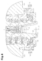
- a 5-axis machining double-housing machine tool according to the present invention which is a machining center 20 according to one embodiment, will now be described with reference to Figs. 1 to 7 .
- the machining center 20 includes a table 24 arranged on a base 22.
- the table 24 is actuated by an X-axis drive motor Mx shown in Fig. 7 , so as to move along an X-axis, which is the lateral and longitudinal direction of the table 24, with a workpiece W mounted thereon.
- a double-housing column 28 extends upward from a column base 26.
- the column 28 has a cross rail 30.
- the cross rail 30 is guided by the column 28, and actuated by a W-axis drive motor Mw shown in Fig. 7 , so as to move upward and downward along a W-axis, which is the same direction as a Z-axis direction extending vertically.
- a saddle 32 is arranged on the cross rail 30.
- the saddle 32 is movable along a Y-axis, which extends horizontally, by a ball screw (not shown) actuated by a Y-axis drive motor My shown in Fig. 7 .
- a ram 34 is attached to the saddle 32 so as to be moved upward and downward by a ball screw (not shown) actuated by a Z-axis drive motor Mz.
- a spindle unit 100 is provided at the lower end of the ram 34.
- An automatic tool changer (ATC) unit 50 is arranged on one side of the double-housing column 28.
- Devices such as a control unit 36 and a main console panel 38 manipulated by an operator are arranged in the vicinity of the base 22.
- a spindle unit 100 has an attachment flange 102 for being attached to the lower end of the ram 34, and a housing 104 integrated with the attachment flange 102.
- the attachment flange 102 is attached to the spindle unit 100 to be rotatable about a C-axis via a bearing 48.
- the ram 34 accommodates a C-axis drive motor 110, which is formed by a stator 42 fixed to a case 40 as shown in Fig. 4 , and a rotor 44 fixed to the attachment flange 102.
- the spindle unit 100 is actuated by the C-axis drive motor 110 to be revolved about the C-axis, which is the axis of the ram 34.
- a hydraulic brake 46 is provided between the rotor 44 and the case 40. The hydraulic brake 46 is capable of stopping the rotating rotor 44 and holding the rotor 44.
- a rotation pipe 60 is integrally fixed to an upper center of the attachment flange 102.
- the rotation pipe 60 extends through the stator 42 as shown in Fig. 4 and is integrally rotatable with the attachment flange 102 about the C-axis of the spindle unit 100.
- a plurality of power wires 62 formed by electric wires or busbars are inserted in the rotation pipe 60.
- Each power wire 62 in the rotation pipe 60 supplies electricity to various types of electric devices in the spindle unit 100, such as a B-axis drive motor 156 and a spindle motor 130.
- the power wires 62 in the rotation pipe 60 are connected to movable portion 73 of a slip ring 70 stored in the ram 34 as shown in Fig. 5 . To facilitate illustration, only part of the power wires are shown in Fig. 5 .
- the slip ring 70 includes a fixed portion 72 fixed to the ram 34 and a movable portion 73 that rotates relative to the fixed portion 72 about the C-axis.
- the fixed portion 72 has an insulating characteristic, and is formed as a cylinder with a lid.
- a plurality of feed elements 76 (brushes) are arranged vertically on the fixed portion 72.
- the feed elements 76 include feed elements for supplying electricity connected to a power source (not shown), and feed elements for sending control signals.
- the signal sending feed elements send control signals such as command signals from the control unit 36 to various types of electric devices such as the spindle motor 130 mounted on the spindle head 100 and the B-axis drive motor 156.
- the movable portion 73 includes an insulating cylinder 74 and a plurality of conductive contacts 75 extending from the insulating cylinder 74 in the radial direction.
- the contacts 75 include contacts that electrically contact the feed elements 76 for supplying power and contacts that contact the feed elements 76 for sending control signals.
- the insulating cylinder 74 is supported by the fixed portion 72 to be pivotable about the C-axis.
- the power wires 62 are inserted into the insulating cylinder 74 and are electrically connected to the contacts 75 for supplying electricity.
- the contacts 75 for supplying electricity are pressed by the feed elements 76 (brushes) for supplying electricity, so as to be electrically connected to the feed elements 76.
- signal lines are also inserted into the insulating cylinder 74, and are electrically connected to the contacts 75 for sending control signals.
- the contacts 75 for sending control signals are also pressed by the feed elements 76 (brushes) for sending control signals, so as to be electrically connected to the feed elements 76.
- signal lines are not shown in Figs. 4 and 5 , and only the power wires 62 for supplying electricity are shown.
- the slip ring 70 applies electricity and control signals through the power lines 62 and the signal lines to the B-axis drive motor 156, the C-axis drive motor 110, and various types of electric devices in the spindle unit 100.
- the slip ring 70 allows the spindle unit 100 to rotate by 360 degrees or a greater angle.
- a pair of fork portions 106 are formed at the lower end of the housing 104 of the spindle unit 100.
- a spindle head 118 is supported between the fork portions 106 to be rotatable about the B-axis perpendicular to the C-axis.
- the spindle head 118 includes a spindle head case 120 and a spindle 124 (main shaft), which is pivotably supported by the spindle head case 120 with a bearing 122.
- the spindle head case 120 accommodates a spindle motor 130, which includes a stator 126 fixed to the spindle head case 120 and a rotor 128 fixed to the spindle 124.
- the spindle motor 130 drives the spindle 124 so that the spindle 124 rotates about the axis thereof.
- a spindle tapered portion 132 is formed at the distal end of the spindle 124.
- a hole 134 extends through the spindle tapered portion 132.
- a known tool clamp device 136 is provided in the hole 134 to be movable along a spindle axis S.
- the right side of the spindle axis S shows a state where a tool K is attached to the tool clamp device 136
- the left side of the spindle axis S shows a state where the tool K is being attached to or detached from the tool clamp device 136.
- a pull stud Ka is provided at the proximal end of the shank of the tool K.
- the tool clamp device 136 shown on the right side of the spindle axis S pulls and fixes the pull stud Ka of the tool K fitted in the spindle tapered portion 132.
- the tool clamp device 136 shown on the left side of the spindle axis S allows the pull stud Ka on the shank of the tool K to be detached or attached.
- a coupling device 140 is provided at a part of the spindle head case 120 that corresponds to the lower part of the spindle 124.
- the coupling device 140 includes a fixed coupling 142 fixed to the spindle head case 120, a rotary coupling 144 fixed to the spindle 124, and movable coupling 146.
- the movable coupling 146 is hydraulically moved toward the fixed coupling 142 to couple the fixed coupling 142 and the rotary coupling 144 to each other.
- the fixed coupling 142 is formed as a ring having a large diameter.
- the rotary coupling 144 has a smaller diameter than the fixed coupling 142 and is coaxial with the fixed coupling 142.
- the right side of the spindle axis S shows a state in which the movable coupling 146 couples the fixed coupling 142 and the rotary coupling 144 to each other. In this coupled state, the spindle 124 cannot be pivoted.
- the movable coupling 146 When receiving no hydraulic pressure, the movable coupling 146 is disengaged from the fixed coupling 142 by the urging force of a spring (not shown). This allows the spindle 124 to rotate. This state is illustrated on the left side of the spindle axis S in Fig. 6 .
- a pair of coaxial shaft portions 148, 150 project from both sides of the spindle head case 120.
- the shaft portions 148, 150 are supported to the housing 104 via bearings 152, 154 to be revolved about the B-axis.
- the B-axis drive motor 156 is accommodated in the housing 104.
- a gear 158 is attached to the output shaft of the B-axis drive motor 156.
- the gear 158 is engaged with a roller gear cam 160 provided nearby.
- the roller gear cam 160 is engaged with a cam follower 162 attached to the shaft portion 150.
- the power wires 62 for supplying electricity to the spindle motor 130 and the electric devices accommodated in the spindle head case 120 are drawn into the spindle head case 120 through the shaft portion 148.
- a brake piston 164 is arranged in the vicinity of the shaft portion 148 in the housing 104.
- the brake piston 164 is moved by hydraulic pressure to contact a brake disc 166 attached to the shaft portion 148.
- the revolution position of the spindle head 118 is fixed and maintained.
- the brake piston 164 releases the brake disc 166, thereby allowing the spindle head 118 to revolve.
- the control unit 36 has a main control section 210, which is a CPU.
- the main control section 210 is connected, via a bus line 205, to a machining program memory 220, a system program memory 230, a buffer memory 240, a machining control section 250, a main console panel 38 having a key board, and a display portion 260 having a liquid crystal display.
- the main control section 210 is also connected, via the bus line 205, to a W-axis control section 270, an X-axis control section 280, a Y-axis control section 290, a Z-axis control section 300, a B-axis control section 310, a C-axis control section 320, and a spindle control section 330.
- the W-axis control section 270, the X-axis control section 280, the Y-axis control section 290, the Z-axis control section 300, the B-axis control section 310, and the C-axis control section 320 output movement commands for each axis output from the main control section 210 to drive circuits 272, 282, 292, 302, 312, 322, respectively.
- the drive circuits drive the motors Mw, Mx, My, Mz, 156, 110 of the axes.
- the main control section 210 is further connected, via the bus line 205, to a hydraulic pressure control section 340, which controls a hydraulic circuit for driving devices such as the coupling device 140 and the brake piston 164.
- the hydraulic pressure control section 340 controls devices such as the coupling device 140 and the brake piston 164.
- the spindle control section 330 Upon receiving a rotation command output from the main control section 210, the spindle control section 330 causes the spindle motor 130 of the spindle head 118 to rotate via the drive circuit 332.
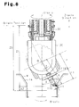
- FIG. 8 shows a state in which the ATC unit 50 (see Fig. 1 ) has replaced the tool K by a non-rotational cutting tool 170 having a cutting tip 172. That is, the non-rotational cutting tool 170 is attached to the distal end of the shank of the spindle head 118 8 as shown in Fig. 8 .
- the non-rotational cutting tool 170 has a pull stud Ka at the proximal end of the shank, as in the case of the tool K shown in Fig. 6 .
- the non-rotational cutting tool 170 is attached to the spindle 124 by clamping the pull stud Ka to the tool clamp device 136. With the non-rotational cutting tool 170 attached, the movable coupling 146 couples the fixed coupling 142 and the rotary coupling 144 to each other, so that the spindle 124 is locked against pivot.
- the order of processes for boring described below is executed by the main control section 210 in accordance with the machining program stored in the machining program memory 220.
- the workpiece W shown in Fig. 8 is fixed onto the table 24.
- the workpiece W has a center 01 like the workpiece W shown in Fig. 12 .
- the center O1 (the center of cutting) of a machining diameter of the workpiece W is set at a predetermined position (step A).
- the predetermined position is a position to which the ram 34 will be moved to align the C-axis, or the axis of the ram 34, with the center O1.
- the Y-axis drive motor My is driven so that the saddle 32 is moved on the cross rail 30 along the Y-axis direction, so that the position on the Y-axis is determined such that the C-axis coincides with the center O1 or the revolution center (step B).
- the B-axis drive motor 156 is driven so that the spindle head 118 is pivoted by a predetermined angle about the B-axis.
- the position of the spindle head 118 is thus determined (step C).
- the predetermined angle is determined in accordance with a value set by the machining program.
- step D After the spindle head 118 is pivoted, the C-axis drive motor 110 is driven, so that the spindle unit 100 is revolved about the C-axis (step D). In this state, the Z-axis drive motor Mz is driven, so that the ram 34 is moved toward the workpiece W along the Z-axis.
- the non-rotational cutting tool 170 attached to the spindle unit 100 is allowed to bore a hole in the workpiece W on the table 24. Accordingly, the workpiece W can be turned while being fixed onto the table 24. That is, a large workpiece can be machined.
- steps A to C in the above description. However, the order is not limited to this. That is, any two of the steps A, B, and C or all three steps may be performed simultaneously. The order is adequately determined in consideration of interference between the workpiece and the tool.
- step E of the above description the ram 34 is moved toward the workpiece W along the Z-axis direction.
- the spindle head 118 is pivoted about the B-axis by a predetermined angle. That is, the boring of the workpiece W is performed with the revolution angle maintained.
- the revolution angle of the spindle head 118 about the B-axis may be changed.
- the hole in the workpiece W has a tapered surface Ta such that the diameter of the hole decreases from the upper surface toward the lower end.
- the hole has a constant diameter at a lower portion.
- the cutting of the tapered surface Ta is performed by changing the revolution angle of the spindle head 118 about the B-axis to gradually reducing the machining diameter while the ram 34 is moved toward the workpiece W along the Z-axis direction. In the lower portion of the hole, the turning is performed while maintaining the revolution angle of the spindle head 118 at a certain value.
- the present embodiment enables forming of holes of different diameters such as tapered holes, by freely changing the machining diameter according to programs.
- the movement amount of the ram 34 along the Z-axis needs to be corrected in accordance with the movement amount of the cutting tip 172 of the non-rotational cutting tool 170 along the Z-axis when the spindle head 118 is rotated about the B-axis.
- a correction amount related to the movement amount in the Z-axis direction is calculated in the following manner.
- Fig. 8 The dimensional relationship shown in Fig. 8 leads to expressions (1) and (2).
- the B-axis When the B-axis is rotated from a position along the C-axis (or 0-degree position of the B-axis) by an angle [theta], the diameter of turning (that is, the machining diameter) is D.
- the revolution of the B-axis creates a movement amount ⁇ Z along the Z-axis direction. This movement amount ⁇ Z needs to be compensated for by using a correction amount.
- the B-axis is revolved downward from the position shown in Fig. 8 by the angle ⁇ , the length is extend by the movement amount ⁇ Z.
- the "origin" is a position that has been adequately set in the ram 34.
- the finished dimension D of machining is expressed by the following expression.
- D ( L ⁇ 1 + L ⁇ 2 x sin ⁇ + r ⁇ 1 x cos ⁇ 2
- a blade edge position correction amount ⁇ Z in the Z-axis direction is expressed by the following expression.
- the main control section 210 combines the correction amount with the movement command in the Z-axis direction, that is, adds or subtracts the correction amount to or from the movement command, and then sends the movement command to the Z-axis control section 300.
- the main control section 210 obtains the value [theta], which is a movement command (that is, the angle command value) to be sent to the B-axis control section 310, in accordance with the following expression (3).
- ⁇ - ⁇ + sin - 1 ⁇ D 2 ⁇ R
- R is the distance from the B-axis rotation center to the blade edge; and [alpha] is the angle defined by the center of the tool and the blade edge.
- the main control section 210 Based on the value [theta], the main control section 210 outputs an angle command value to the B-axis control section 310.
- the movement amount of the ram 34 along the Z-axis is corrected in accordance with the movement amount of the cutting tip 172 of the non-rotational cutting tool 170 along the Z-axis when the spindle head 118 is rotated about the B-axis. This allows the spindle head 118 to be adequately moved along the Z-axis direction.
- the non-rotational cutting tool 170 is directly attached to the spindle 124 shown in Fig. 6 in the previous embodiment.
- an attachment 350 may be removably attached to the end face of the spindle head 118, and the non-rotational cutting tool 170 may be attached to the attachment 350.
- a spindle head 118 has on its end face 116 (that is, on the head end) four clamp devices 180 at four corners about a spindle 124.
- the attachment 350 has an attaching portion 354 shaped as a cuboid with an attachment end face 352 conforming to the shape of the end face of the spindle head 118, and a tool attaching portion 356 shaped as a rectangular tube which is provided on the side opposite to the attachment end face 352 and receives the non-rotational cutting tool 170.
- the non-rotational cutting tool 170 is fixed to the tool attaching portion 356 such that the axis of the spindle 124 shown in Fig. 6 is parallel to the axis of the non-rotational cutting tool 170 when the attachment 350 is attached to the spindle head 118.
- the tool attaching portion 356 is configured such that the axis of the spindle 124 shown in Fig. 6 is offset by a greater amount from the blade edge of the cutting tip 172 of the non-rotational cutting tool 170 when the attachment 350 is attached to the spindle head 118, than in the previous embodiment.
- the embodiment provides four clamp seats 358 at four corners of the attaching end face of the attaching portion 354.
- the numbers of the clamp devices 180 and the clamp seats 358 are not limited, but the numbers are preferably plural.
- the attachment 350 is attached to the spindle head 118 by bringing the attachment end face 352 (see Fig. 10(a) ) into contact with the end face 116 of the spindle head 118 (see Figs. 9(a) to 9(c) ), and causing the clamp seats 358 shown in Fig. 10(a) to be clamped by the clamp devices 180 of the spindle head 118.
- the attachment 350 can be removed from the spindle head 118.
- the present embodiment configured as described so far allows boring to be performed to a workpiece W in the same method as in the previous embodiment.
- the distance r1 from the center of the spindle 124 (main shaft) to the blade tip of the cutting tip 172 which is expressed in the expressions (1), (2), and (3), is set to a greater value than that in the present embodiment.
- changes in the cutting edge angle at the boring operation can be reduced.
- the hydraulic circuit for actuating the coupling device 140 and the brake piston 164 may be replaced by a pneumatic circuit.
- the cross rail 30 is movable along the W-axis direction.
- the cross rail 30 may be immovable along the W-axis direction, and only the ram 34 may be movable along the Z-axis direction relative to the saddle 32.
Description
- The present invention relates to a method of workpiece boring by a 5-axis machining double-housing machine tool according to the preamble of claim 1.
- Conventionally, when a large workpiece is turned, a large-sized lathe is generally used. However, if the workpiece is not in good balance, the rotation rate of the workpiece is limited. This requires a great reduction in the cutting speed conditions such as the feed rate. To deal with this drawback, a counterweight may be attached to the workpiece so as to improve the balance. However, this countermeasure increases the energy consumption due to the addition of the counterweight when the workpiece is rotated, and limits the weight of the workpiece.
- Hereinafter, a prior art technique for turning a large workpiece will be described.
- A workpiece W shown in
Fig. 12 is a large workpiece having a weight of 1160 kg. The machining diameter of a hole Wa to be formed through boring is 730 mm. - When the workpiece W is machined by being revolved about a center O1 which is displaced from the center of gravity O of the workpiece W, the maximum diameter of the swing of the workpiece W is 2330 mm as shown in
Fig. 12 (the radius from the center O1 being 1155 mm). In the example of this workpiece W, since the center of gravity O is at the position of 237 mm away from the revolution center, the rotation of the workpiece W is imbalanced. - To perform such machining, a significantly large vertical lathe is necessary. In other words, the turning of the workpiece W needs to be performed by a different large vertical lathe, which significantly extends the overall machining time.
- Accordingly, to avoid such a turning process, circularity machining is performed as shown in
Fig. 13 . The circularity machining refers to a process in which a workpiece W fixed onto a table is moved along a hole Wa while an end mill is rotated. The circularity machining allows machining of other parts of the workpiece W to be performed with the same machine tool. However, the machining accuracy of the circularity machining is inferior to that of a turning process. - As described above, conventionally, a large workpiece that is difficult to rotate is machined in the following manner. That is, such a workpiece is subjected to the circularity machining by an end mill, which sacrifices machining accuracy and machined surface. The workpiece is also subjected to a turning process using a horizontal boring machine, or a boring process performed by rotating the workpiece with a large vertical lathe in the knowledge of a resultant imbalance. In other words, machining processes are switched, which requires setup of workpiece and tools each time.
- Patent Document 1 discloses boring by a horizontal boring machine.
- Patent Document 1: Japanese Laid-Open Patent Publication No.
58-28408 -
WO 2008/050747 discloses an indexing head that can be rotated and a rotational spindle unit that is rotated. -
JP6005801 U - Accordingly, it is an objective of the present invention to provide a method of workpiece boring by a 5-axis machining double-housing machine tool and a 5-axis machining double-housing machine tool that eliminate the necessity for changeovers without sacrificing machining accuracy and machined surfaces, in other words, a method and a machine tool that are capable of machining a large workpiece that is fixed to a table.
- To achieve the foregoing objective, a method of workpiece boring by a 5-axis machining double-housing machine tool is provided. The machine tool includes: a table and a double-housing column that are movable relative to each other along an X-axis extending horizontally; a cross rail that is either fixed on a Z-axis or movable upward and downward along the Z-axis, the Z-axis extending vertically along the column; a saddle that is movable along a Y axis extending on the cross rail along a horizontal direction; a ram supported to the saddle to be movable upward and downward along the Z-axis; a spindle unit that is attached to a lower end of the ram to be revolvable about a C-axis, which is an axis of the ram; and a spindle head that is attached to the spindle unit to be revolvable about a B-axis, which is perpendicular to the C-axis. The method further includes, after determining the position of the saddle in the Y-axis direction and the position of the table in the X-axis direction, moving the ram along the Z-axis direction with the spindle unit revolved about the C-axis; and, with a non-rotational cutting tool attached to the spindle head, boring a hole in a workpiece on the table, the machining diameter of the hole being determined by the position about the B-axis of the spindle head.
- In accordance with this configuration, the 5-axis machining double-housing machine tool performs boring by revolving a spindle unit about the C-axis, which allows the workpiece to be performed turning while being fixed. Thus, highly accurate and high quality boring of large workpieces is possible without a changeover to another specialized machine tool to avoid imbalance of the workpiece. Also, the machining diameter of the hole can be changed by adjusting the position of the spindle head about the B-axis. Thus, unlike a boring process with a constant machining diameter, holes of different diameters can be formed by changing the program.
- While the ram is being moved along the Z-axis direction, the spindle head is preferably rotated about the B-axis to change the machining diameter of the workpiece.
- According to this configuration, unlike a boring process with a constant machining diameter, the machining diameter of the hole can be easily changed by changing the program, allowing holes of various shapes, for example, tapered shapes, to be formed.
- When the machining diameter of the workpiece is changed by rotating the spindle head about the B-axis while the ram is being moved along the Z-axis direction, the movement amount of the ram along the Z-axis direction is preferably corrected in accordance with the movement amount of a cutting tip of the non-rotational cutting tool along the Z-axis direction when the spindle head is rotated about the B-axis.
- According to this configuration, the spindle head can be adequately moved along the Z-axis.
- This configuration provides a 5-axis machining double-housing machine tool that can be directly used for the above described method of workpiece boring by a 5-axis machining double-housing machine tool.
-
-
Fig. 1 is a schematic front perspective view illustrating a multi-face 5-axis machining double-housing machining center according to one embodiment of the present invention; -
Fig. 2 is a perspective view showing the appearance of the spindle unit; -
Fig. 3 is a cross-sectional view showing the spindle unit; -
Fig. 4 is a partial cross-sectional view showing the ram; -
Fig. 5 is a diagram showing the slip ring; -
Fig. 6 is an enlarged partial diagram showing the spindle; -
Fig. 7 is an electric block diagram showing the control unit; -
Fig. 8 is a diagram showing operation of the machining center; -
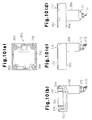
Fig. 9(a) is a front view showing a spindle unit according to another embodiment; -
Fig. 9(b) is a side view showing the spindle unit; -
Fig. 9(c) is a bottom view showing the spindle unit; -
Fig. 10(a) is a plan view showing an attachment; -
Fig. 10(b) is a cross-sectional view showing the attachment; -
Fig. 10(c) is a front view showing the attachment; -
Fig. 10(d) is a side view showing the attachment; -
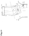
Fig. 11 is a diagram showing operation of the machining center; -
Fig. 12 is a plan view showing a workpiece; and -
Fig. 13 is a diagram showing a conventional boring operation. - A 5-axis machining double-housing machine tool according to the present invention, which is a
machining center 20 according to one embodiment, will now be described with reference toFigs. 1 to 7 . - As shown in
Fig. 1 , themachining center 20 includes a table 24 arranged on abase 22. The table 24 is actuated by an X-axis drive motor Mx shown inFig. 7 , so as to move along an X-axis, which is the lateral and longitudinal direction of the table 24, with a workpiece W mounted thereon. - A double-
housing column 28 extends upward from acolumn base 26. Thecolumn 28 has across rail 30. Thecross rail 30 is guided by thecolumn 28, and actuated by a W-axis drive motor Mw shown inFig. 7 , so as to move upward and downward along a W-axis, which is the same direction as a Z-axis direction extending vertically. Asaddle 32 is arranged on thecross rail 30. Thesaddle 32 is movable along a Y-axis, which extends horizontally, by a ball screw (not shown) actuated by a Y-axis drive motor My shown inFig. 7 . Aram 34 is attached to thesaddle 32 so as to be moved upward and downward by a ball screw (not shown) actuated by a Z-axis drive motor Mz. Aspindle unit 100 is provided at the lower end of theram 34. - An automatic tool changer (ATC)
unit 50 is arranged on one side of the double-housing column 28. Devices such as acontrol unit 36 and amain console panel 38 manipulated by an operator are arranged in the vicinity of thebase 22. - As shown in
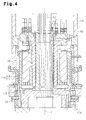
Fig. 2 , aspindle unit 100 has anattachment flange 102 for being attached to the lower end of theram 34, and ahousing 104 integrated with theattachment flange 102. As shown inFig. 4 , theattachment flange 102 is attached to thespindle unit 100 to be rotatable about a C-axis via abearing 48. Theram 34 accommodates a C-axis drive motor 110, which is formed by a stator 42 fixed to acase 40 as shown inFig. 4 , and arotor 44 fixed to theattachment flange 102. Thespindle unit 100 is actuated by the C-axis drive motor 110 to be revolved about the C-axis, which is the axis of theram 34. Ahydraulic brake 46 is provided between therotor 44 and thecase 40. Thehydraulic brake 46 is capable of stopping therotating rotor 44 and holding therotor 44. - As shown in
Fig. 4 , arotation pipe 60 is integrally fixed to an upper center of theattachment flange 102. Therotation pipe 60 extends through the stator 42 as shown inFig. 4 and is integrally rotatable with theattachment flange 102 about the C-axis of thespindle unit 100. A plurality ofpower wires 62 formed by electric wires or busbars are inserted in therotation pipe 60. Eachpower wire 62 in therotation pipe 60 supplies electricity to various types of electric devices in thespindle unit 100, such as a B-axis drive motor 156 and aspindle motor 130. - The
power wires 62 in therotation pipe 60 are connected tomovable portion 73 of aslip ring 70 stored in theram 34 as shown inFig. 5 . To facilitate illustration, only part of the power wires are shown inFig. 5 . - As shown in
Fig. 5 , theslip ring 70 includes a fixedportion 72 fixed to theram 34 and amovable portion 73 that rotates relative to the fixedportion 72 about the C-axis. The fixedportion 72 has an insulating characteristic, and is formed as a cylinder with a lid. A plurality of feed elements 76 (brushes) are arranged vertically on the fixedportion 72. - The
feed elements 76 include feed elements for supplying electricity connected to a power source (not shown), and feed elements for sending control signals. The signal sending feed elements send control signals such as command signals from thecontrol unit 36 to various types of electric devices such as thespindle motor 130 mounted on thespindle head 100 and the B-axis drive motor 156. - The
movable portion 73 includes an insulatingcylinder 74 and a plurality ofconductive contacts 75 extending from the insulatingcylinder 74 in the radial direction. Thecontacts 75 include contacts that electrically contact thefeed elements 76 for supplying power and contacts that contact thefeed elements 76 for sending control signals. The insulatingcylinder 74 is supported by the fixedportion 72 to be pivotable about the C-axis. - The
power wires 62 are inserted into the insulatingcylinder 74 and are electrically connected to thecontacts 75 for supplying electricity. Thecontacts 75 for supplying electricity are pressed by the feed elements 76 (brushes) for supplying electricity, so as to be electrically connected to thefeed elements 76. Although not illustrated, signal lines are also inserted into the insulatingcylinder 74, and are electrically connected to thecontacts 75 for sending control signals. Thecontacts 75 for sending control signals are also pressed by the feed elements 76 (brushes) for sending control signals, so as to be electrically connected to thefeed elements 76. To facilitate illustration, signal lines are not shown inFigs. 4 and5 , and only thepower wires 62 for supplying electricity are shown. - The
slip ring 70 applies electricity and control signals through thepower lines 62 and the signal lines to the B-axis drive motor 156, the C-axis drive motor 110, and various types of electric devices in thespindle unit 100. Theslip ring 70 allows thespindle unit 100 to rotate by 360 degrees or a greater angle. - As shown in
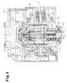
Fig. 3 , a pair offork portions 106 are formed at the lower end of thehousing 104 of thespindle unit 100. Aspindle head 118 is supported between thefork portions 106 to be rotatable about the B-axis perpendicular to the C-axis. - The
spindle head 118 includes aspindle head case 120 and a spindle 124 (main shaft), which is pivotably supported by thespindle head case 120 with abearing 122. Thespindle head case 120 accommodates aspindle motor 130, which includes astator 126 fixed to thespindle head case 120 and arotor 128 fixed to thespindle 124. Thespindle motor 130 drives thespindle 124 so that thespindle 124 rotates about the axis thereof. - As shown in
Fig. 6 , a spindle taperedportion 132 is formed at the distal end of thespindle 124. Ahole 134 extends through the spindle taperedportion 132. A knowntool clamp device 136 is provided in thehole 134 to be movable along a spindle axis S. InFig. 6 , for purposes of illustration, the right side of the spindle axis S shows a state where a tool K is attached to thetool clamp device 136, and the left side of the spindle axis S shows a state where the tool K is being attached to or detached from thetool clamp device 136. - A pull stud Ka is provided at the proximal end of the shank of the tool K. The
tool clamp device 136 shown on the right side of the spindle axis S pulls and fixes the pull stud Ka of the tool K fitted in the spindle taperedportion 132. Thetool clamp device 136 shown on the left side of the spindle axis S allows the pull stud Ka on the shank of the tool K to be detached or attached. - A
coupling device 140 is provided at a part of thespindle head case 120 that corresponds to the lower part of thespindle 124. Thecoupling device 140 includes a fixedcoupling 142 fixed to thespindle head case 120, arotary coupling 144 fixed to thespindle 124, andmovable coupling 146. Themovable coupling 146 is hydraulically moved toward the fixedcoupling 142 to couple the fixedcoupling 142 and therotary coupling 144 to each other. - The fixed
coupling 142 is formed as a ring having a large diameter. Therotary coupling 144 has a smaller diameter than the fixedcoupling 142 and is coaxial with the fixedcoupling 142. - The right side of the spindle axis S shows a state in which the
movable coupling 146 couples the fixedcoupling 142 and therotary coupling 144 to each other. In this coupled state, thespindle 124 cannot be pivoted. - When receiving no hydraulic pressure, the
movable coupling 146 is disengaged from the fixedcoupling 142 by the urging force of a spring (not shown). This allows thespindle 124 to rotate. This state is illustrated on the left side of the spindle axis S inFig. 6 . - As shown in
Fig. 3 , a pair ofcoaxial shaft portions 148, 150 project from both sides of thespindle head case 120. Theshaft portions 148, 150 are supported to thehousing 104 viabearings - The B-
axis drive motor 156 is accommodated in thehousing 104. Agear 158 is attached to the output shaft of the B-axis drive motor 156. Thegear 158 is engaged with aroller gear cam 160 provided nearby. Theroller gear cam 160 is engaged with acam follower 162 attached to theshaft portion 150. When the B-axis drive motor 156 rotates, thespindle head 118 is revolved about the B-axis via theshaft portion 150. - Although not illustrated, the
power wires 62 for supplying electricity to thespindle motor 130 and the electric devices accommodated in thespindle head case 120 are drawn into thespindle head case 120 through the shaft portion 148. - A
brake piston 164 is arranged in the vicinity of the shaft portion 148 in thehousing 104. Thebrake piston 164 is moved by hydraulic pressure to contact a brake disc 166 attached to the shaft portion 148. By activating thebrake piston 164 in this manner, the revolution position of thespindle head 118 is fixed and maintained. When the applied hydraulic pressure is cancelled, thebrake piston 164 releases the brake disc 166, thereby allowing thespindle head 118 to revolve. - As shown in
Fig. 7 , thecontrol unit 36 has amain control section 210, which is a CPU. Themain control section 210 is connected, via abus line 205, to amachining program memory 220, asystem program memory 230, abuffer memory 240, amachining control section 250, amain console panel 38 having a key board, and adisplay portion 260 having a liquid crystal display. - The
main control section 210 is also connected, via thebus line 205, to a W-axis control section 270, anX-axis control section 280, a Y-axis control section 290, a Z-axis control section 300, a B-axis control section 310, a C-axis control section 320, and aspindle control section 330. The W-axis control section 270, theX-axis control section 280, the Y-axis control section 290, the Z-axis control section 300, the B-axis control section 310, and the C-axis control section 320 output movement commands for each axis output from themain control section 210 to drivecircuits - The
main control section 210 is further connected, via thebus line 205, to a hydraulicpressure control section 340, which controls a hydraulic circuit for driving devices such as thecoupling device 140 and thebrake piston 164. The hydraulicpressure control section 340 controls devices such as thecoupling device 140 and thebrake piston 164. - Upon receiving a rotation command output from the
main control section 210, thespindle control section 330 causes thespindle motor 130 of thespindle head 118 to rotate via thedrive circuit 332. - A method for boring a hole in a workpiece W using the above described
machining center 20 will now be described. - To facilitate illustration,
Fig. 8 shows a state in which the ATC unit 50 (seeFig. 1 ) has replaced the tool K by anon-rotational cutting tool 170 having a cuttingtip 172. That is, thenon-rotational cutting tool 170 is attached to the distal end of the shank of thespindle head 118 8 as shown inFig. 8 . Thenon-rotational cutting tool 170 has a pull stud Ka at the proximal end of the shank, as in the case of the tool K shown inFig. 6 . Thenon-rotational cutting tool 170 is attached to thespindle 124 by clamping the pull stud Ka to thetool clamp device 136. With thenon-rotational cutting tool 170 attached, themovable coupling 146 couples the fixedcoupling 142 and therotary coupling 144 to each other, so that thespindle 124 is locked against pivot. - The order of processes for boring described below is executed by the
main control section 210 in accordance with the machining program stored in themachining program memory 220. The workpiece W shown inFig. 8 is fixed onto the table 24. The workpiece W has acenter 01 like the workpiece W shown inFig. 12 . - When the X-axis drive motor Mx shown in
Fig. 7 is driven and the table 24 starts moving, the center O1 (the center of cutting) of a machining diameter of the workpiece W is set at a predetermined position (step A). The predetermined position is a position to which theram 34 will be moved to align the C-axis, or the axis of theram 34, with the center O1. - Then, the Y-axis drive motor My is driven so that the
saddle 32 is moved on thecross rail 30 along the Y-axis direction, so that the position on the Y-axis is determined such that the C-axis coincides with the center O1 or the revolution center (step B). - Then, the B-
axis drive motor 156 is driven so that thespindle head 118 is pivoted by a predetermined angle about the B-axis. The position of thespindle head 118 is thus determined (step C). The predetermined angle is determined in accordance with a value set by the machining program. - After the
spindle head 118 is pivoted, the C-axis drive motor 110 is driven, so that thespindle unit 100 is revolved about the C-axis (step D). In this state, the Z-axis drive motor Mz is driven, so that theram 34 is moved toward the workpiece W along the Z-axis. - As a result, the
non-rotational cutting tool 170 attached to thespindle unit 100 is allowed to bore a hole in the workpiece W on the table 24. Accordingly, the workpiece W can be turned while being fixed onto the table 24. That is, a large workpiece can be machined. - The order of steps is A to C in the above description. However, the order is not limited to this. That is, any two of the steps A, B, and C or all three steps may be performed simultaneously. The order is adequately determined in consideration of interference between the workpiece and the tool.
- In step E of the above description, the
ram 34 is moved toward the workpiece W along the Z-axis direction. At this time, thespindle head 118 is pivoted about the B-axis by a predetermined angle. That is, the boring of the workpiece W is performed with the revolution angle maintained. However, in the step E, in which theram 34 is moved toward the workpiece W along the Z-axis direction according to the machining program, the revolution angle of thespindle head 118 about the B-axis may be changed. - For example, in the example shown in
Fig. 8 , the hole in the workpiece W has a tapered surface Ta such that the diameter of the hole decreases from the upper surface toward the lower end. The hole has a constant diameter at a lower portion. In this example, the cutting of the tapered surface Ta is performed by changing the revolution angle of thespindle head 118 about the B-axis to gradually reducing the machining diameter while theram 34 is moved toward the workpiece W along the Z-axis direction. In the lower portion of the hole, the turning is performed while maintaining the revolution angle of thespindle head 118 at a certain value. - Thus, unlike a boring process with a fixed machining diameter, the present embodiment enables forming of holes of different diameters such as tapered holes, by freely changing the machining diameter according to programs.
- When forming a hole with a larger diameter at a lower portion than in an upper portion in the workpiece W, it is possible to bore such a hole with the cutting
tip 172 under an advantageous condition. - When changing the machining diameter of the workpiece W by rotating (revolving) the
spindle head 118 about the B axis while theram 34 is moved along the Z-axis, the movement amount of theram 34 along the Z-axis needs to be corrected in accordance with the movement amount of thecutting tip 172 of thenon-rotational cutting tool 170 along the Z-axis when thespindle head 118 is rotated about the B-axis. - Specifically, a correction amount related to the movement amount in the Z-axis direction is calculated in the following manner.
- The dimensional relationship shown in
Fig. 8 leads to expressions (1) and (2). When the B-axis is rotated from a position along the C-axis (or 0-degree position of the B-axis) by an angle [theta], the diameter of turning (that is, the machining diameter) is D. The revolution of the B-axis creates a movement amount ΔZ along the Z-axis direction. This movement amount ΔZ needs to be compensated for by using a correction amount. When the B-axis is revolved downward from the position shown inFig. 8 by the angle θ, the length is extend by the movement amount ΔZ. InFig. 8 , the "origin" is a position that has been adequately set in theram 34. - The finished dimension D of machining is expressed by the following expression.

- A blade edge position correction amount ΔZ in the Z-axis direction is expressed by the following expression.

where: - D is the finished dimension of machining;
- L1 is the tool length;
- L2 is the distance from the B-axis rotation center to the spindle end face;
- r1 is the distance from the center of the spindle to the blade edge;
- θ is the control angle of the B-axis;
- Z0 is the position of the blade edge when the B-axis is at the 0-degree position; and
- Z1 is the position of the blade edge after B-axis is revolved.
- The
main control section 210 combines the correction amount with the movement command in the Z-axis direction, that is, adds or subtracts the correction amount to or from the movement command, and then sends the movement command to the Z-axis control section 300. - From the expression (1), the
main control section 210 obtains the value [theta], which is a movement command (that is, the angle command value) to be sent to the B-axis control section 310, in accordance with the following expression (3).
where: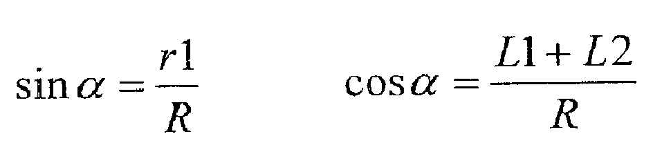

- R is the distance from the B-axis rotation center to the blade edge; and [alpha] is the angle defined by the center of the tool and the blade edge.
- Based on the value [theta], the
main control section 210 outputs an angle command value to the B-axis control section 310. - In this manner, when changing the machining diameter of the workpiece W by rotating the
spindle head 118 about the B axis while theram 34 is moved along the Z-axis, the movement amount of theram 34 along the Z-axis is corrected in accordance with the movement amount of thecutting tip 172 of thenon-rotational cutting tool 170 along the Z-axis when thespindle head 118 is rotated about the B-axis. This allows thespindle head 118 to be adequately moved along the Z-axis direction. - Next other embodiments will be described with reference to
Figs. 8 to 11 . Like or the same reference numerals are given to those components that are like or the same as the corresponding components of the above embodiment, and detailed explanations are omitted. - Descriptions will be given for different components.
- As shown in
Fig. 8 , thenon-rotational cutting tool 170 is directly attached to thespindle 124 shown inFig. 6 in the previous embodiment. However, anattachment 350 may be removably attached to the end face of thespindle head 118, and thenon-rotational cutting tool 170 may be attached to theattachment 350. - As shown in
Figs. 9(a) to 9(c) , aspindle head 118 has on its end face 116 (that is, on the head end) fourclamp devices 180 at four corners about aspindle 124. - On the other hand, as shown in
Figs. 9(a) to 9(c) andFigs. 10(a) to 10(d) , theattachment 350 has an attachingportion 354 shaped as a cuboid with anattachment end face 352 conforming to the shape of the end face of thespindle head 118, and atool attaching portion 356 shaped as a rectangular tube which is provided on the side opposite to theattachment end face 352 and receives thenon-rotational cutting tool 170. - As shown in
Fig. 11 , thenon-rotational cutting tool 170 is fixed to thetool attaching portion 356 such that the axis of thespindle 124 shown inFig. 6 is parallel to the axis of thenon-rotational cutting tool 170 when theattachment 350 is attached to thespindle head 118. As shown inFig. 11 , thetool attaching portion 356 is configured such that the axis of thespindle 124 shown inFig. 6 is offset by a greater amount from the blade edge of thecutting tip 172 of thenon-rotational cutting tool 170 when theattachment 350 is attached to thespindle head 118, than in the previous embodiment. As shown inFig. 10(a) , the embodiment provides fourclamp seats 358 at four corners of the attaching end face of the attachingportion 354. - The numbers of the
clamp devices 180 and the clamp seats 358 are not limited, but the numbers are preferably plural. - Then, as shown in
Fig. 11 , theattachment 350 is attached to thespindle head 118 by bringing the attachment end face 352 (seeFig. 10(a) ) into contact with theend face 116 of the spindle head 118 (seeFigs. 9(a) to 9(c) ), and causing the clamp seats 358 shown inFig. 10(a) to be clamped by theclamp devices 180 of thespindle head 118. When the clamping by theclamp devices 180 is cancelled, theattachment 350 can be removed from thespindle head 118. - The present embodiment configured as described so far allows boring to be performed to a workpiece W in the same method as in the previous embodiment.
- In the case of an attachment head as in the present embodiment, the distance r1 from the center of the spindle 124 (main shaft) to the blade tip of the
cutting tip 172, which is expressed in the expressions (1), (2), and (3), is set to a greater value than that in the present embodiment. Thus, changes in the cutting edge angle at the boring operation can be reduced. - In each of the above embodiments, the hydraulic circuit for actuating the
coupling device 140 and thebrake piston 164 may be replaced by a pneumatic circuit. - In each of the above embodiments, the
cross rail 30 is movable along the W-axis direction. However, thecross rail 30 may be immovable along the W-axis direction, and only theram 34 may be movable along the Z-axis direction relative to thesaddle 32. -
- 24 ... Table, 28 ... Column, 30 ... Cross rail, 32 ... Saddle
- 34 ... Ram, 70 ... Slip ring, 72 ... Fixed portion, 75 ... Contact
- 76 ... Feed element, 100 ... Spindle unit, 118 ... Spindle head
- 120 ... Spindle head case, 170 ... Non-rotational cutting tool
- 172 ... Cutting tip, 350 ... Attachment
Claims (3)
- A method of workpiece boring by a 5-axis machining double-housing machine tool, wherein the machine tool includes: a table and a double-housing column that are movable relative to each other along an X-axis extending horizontally; a cross rail (30) that is either fixed on a Z-axis or movable upward and downward along the Z-axis, the Z-axis extending vertically along the column; a saddle that is movable along a Y-axis extending on the cross rail (30) along a horizontal direction; a ram (34) supported to the saddle (32) to be movable upward and downward along the Z-axis; a spindle unit that is attached to a lower end of the ram (34) to be revolvable about a C-axis, which is an axis of the ram; and a spindle head (118) that is attached to the spindle unit (100) to be revolvable about a B-axis, which is perpendicular to the C-axis,
the method being characterized by, after determining the position of the saddle in the Y-axis direction and the position of the table in the X-axis direction, moving the ram along the Z-axis direction with the spindle unit (100) revolved about the C-axis; and, with a non-rotational cutting tool (170) attached to the spindle head, boring a hole in a workpiece on the table, the machining diameter of the hole being determined by the position about the B-axis of the spindle head (118). - The method of boring work by a 5-axis machining double-housing machine tool according to claim 1, being characterized by, while the ram is being moved along the Z-axis direction, rotating the spindle head about the B-axis to change the machining diameter of the workpiece.
- The method of boring work by a 5-axis machining double-housing machine tool according to claim 2, being characterized by, when the machining diameter of the workpiece is changed by rotating the spindle head about the B-axis while the ram is being moved along the Z-axis direction, correcting the movement amount of the ram along the Z-axis direction in accordance with the movement amount of a cutting tip of the non-rotational cutting tool along the Z-axis direction when the spindle head is rotated about the B-axis.
Applications Claiming Priority (2)
| Application Number | Priority Date | Filing Date | Title |
|---|---|---|---|
| JP2008307777 | 2008-12-02 | ||
| PCT/JP2009/065183 WO2010064478A1 (en) | 2008-12-02 | 2009-08-31 | Method of boring work by 5-axis machining double-housing machine tool and 5-axis machining double-housing machine tool |
Publications (3)
| Publication Number | Publication Date |
|---|---|
| EP2353757A1 EP2353757A1 (en) | 2011-08-10 |
| EP2353757A4 EP2353757A4 (en) | 2012-05-02 |
| EP2353757B1 true EP2353757B1 (en) | 2014-12-24 |
Family
ID=42233133
Family Applications (1)
| Application Number | Title | Priority Date | Filing Date |
|---|---|---|---|
| EP09830246.6A Active EP2353757B1 (en) | 2008-12-02 | 2009-08-31 | Method of workpiece boring by a 5-axis machining double-housing machine tool |
Country Status (5)
| Country | Link |
|---|---|
| US (1) | US8950987B2 (en) |
| EP (1) | EP2353757B1 (en) |
| JP (1) | JP5204246B2 (en) |
| CN (1) | CN102216008B (en) |
| WO (1) | WO2010064478A1 (en) |
Families Citing this family (17)
| Publication number | Priority date | Publication date | Assignee | Title |
|---|---|---|---|---|
| JP5784410B2 (en) * | 2011-08-17 | 2015-09-24 | Thk株式会社 | Five-sided processing machine and rotary table mechanism used therefor |
| USD735253S1 (en) * | 2011-12-23 | 2015-07-28 | Giesecke & Devrient, Gmbh | Working machine |
| KR101342928B1 (en) * | 2012-02-16 | 2013-12-19 | 주식회사 남선기공 | Two shaft automatic turning use Head equipment |
| CN102632266A (en) * | 2012-04-15 | 2012-08-15 | 苏州怡信光电科技有限公司 | Method for machining hand wheel square groove |
| CN104736280B (en) * | 2012-12-20 | 2016-08-17 | 山崎马扎克公司 | The internal diameter turning adnexa of lathe |
| DE102013111599A1 (en) * | 2013-10-21 | 2015-08-06 | Feinmechanik Michael Deckel Gmbh & Co Kg | Spindle of a tool grinding machine |
| CN103722207B (en) * | 2013-12-23 | 2016-04-20 | 沈阳飞机工业(集团)有限公司 | Towards automatic punching equipment and the method for drilling thereof of composite aerofoil base part |
| CN105033827B (en) * | 2015-07-09 | 2018-04-10 | 深圳蓝狐思谷科技有限公司 | A kind of full-automatic sanding polissoir |
| US20170197287A1 (en) * | 2016-01-07 | 2017-07-13 | Toshiba Kikai Kabushiki Kaisha | Machine tool and method for correcting a position of a tip of the tool |
| US20180111221A1 (en) * | 2016-10-21 | 2018-04-26 | Esab Ab | Arcuate boom for friction stir welding of arcuate work pieces |
| CN106736631A (en) * | 2017-01-13 | 2017-05-31 | 杨远双 | A kind of CNC milling machine |
| CN108857462B (en) * | 2018-07-25 | 2023-09-12 | 科益展智能装备有限公司 | Hollow harmonic platform for processing mobile phone parts |
| EP3623104B1 (en) * | 2018-09-12 | 2021-08-11 | FIDIA S.p.A. | C-axis unit for a machine tool with an electrospindle |
| CN110509108A (en) * | 2019-09-19 | 2019-11-29 | 意特利(滁州)智能数控科技有限公司 | A kind of full protection Five-axis NC Machining Center |
| CN112705748A (en) * | 2020-12-21 | 2021-04-27 | 南京肯迈得机床制造有限公司 | Multi-shaft inclined straight hole machining method |
| CN114453614A (en) * | 2022-03-11 | 2022-05-10 | 唐山学院 | Small-size drilling machine capable of adjusting position and angle |
| CN114905295A (en) * | 2022-04-26 | 2022-08-16 | 津上精密机床(浙江)有限公司 | Cutter table capable of improving machining efficiency |
Family Cites Families (28)
| Publication number | Priority date | Publication date | Assignee | Title |
|---|---|---|---|---|
| DE1552393B1 (en) * | 1966-10-31 | 1969-10-16 | Froriep Gmbh Maschf | Heavy machine tool |
| JPS5828408A (en) | 1981-08-07 | 1983-02-19 | Toshiba Mach Co Ltd | Boring machine |
| JPH071206A (en) * | 1992-02-13 | 1995-01-06 | Enshu Ltd | Rotary joint device of universal head |
| JPH065801U (en) * | 1993-02-18 | 1994-01-25 | 株式会社森精機製作所 | Detachable U-axis control unit for machine tools |
| US5584621A (en) * | 1995-06-13 | 1996-12-17 | Bertsche Engineering Corp. | Direct drive multiple axes rotary spindle head for milling machine |
| US6352496B1 (en) * | 2000-01-28 | 2002-03-05 | Imta Manufacturing Technology & Automation Company | High-speed milling machine with rotary table |
| JP4198861B2 (en) * | 2000-03-23 | 2008-12-17 | 東芝機械株式会社 | Correction method of machine error at spindle head of multi-axis machine tool |
| US6474913B2 (en) * | 2000-05-31 | 2002-11-05 | Toshiba Kikai Kabushiki Kaisha | Tool management system |
| JP3763734B2 (en) * | 2000-10-27 | 2006-04-05 | 株式会社日立製作所 | Panel member processing method |
| DE20204365U1 (en) * | 2002-03-19 | 2002-05-29 | Deckel Maho Pfronten Gmbh | Spindle head for a universal milling machine |
| JP4715081B2 (en) * | 2003-08-12 | 2011-07-06 | コニカミノルタオプト株式会社 | Processing machine |
| JP4672299B2 (en) * | 2004-07-26 | 2011-04-20 | ヤマザキマザック株式会社 | Balancer mounting angle calculation method for machine tool and machine tool |
| US7357769B2 (en) * | 2005-05-25 | 2008-04-15 | Mori Seiki Co., Ltd. | Machine tool |
| US7506423B2 (en) | 2005-06-15 | 2009-03-24 | Mori Seiki Co., Ltd. | Multi-axis turning center and turning method |
| US7172375B2 (en) * | 2005-06-23 | 2007-02-06 | Mori Seiki Co., Ltd. | Machine tool |
| ITBO20060500A1 (en) * | 2006-06-29 | 2007-12-30 | Jobs Spa | MULTIPLE TOOL MACHINE. |
| TW200810876A (en) | 2006-08-23 | 2008-03-01 | Tsudakoma Ind Co Ltd | Machining head for machine tool |
| JP5085998B2 (en) * | 2006-08-23 | 2012-11-28 | 津田駒工業株式会社 | Machining head for machine tools |
| CN200954556Y (en) | 2006-10-13 | 2007-10-03 | 沈阳新正数控机床有限责任公司 | Five-coordinate numerical-controlled oil-spraying-hole drilling machine tool |
| TW200827092A (en) * | 2006-10-18 | 2008-07-01 | Tsudakoma Ind Co Ltd | Processing head for machine tool |
| TW200821083A (en) * | 2006-10-26 | 2008-05-16 | Tsudakoma Ind Co Ltd | Angle indexing device for machine tool |
| US8641338B2 (en) * | 2006-12-27 | 2014-02-04 | Nsk Ltd. | Spindle device, machining center including the spindle device, and method for assembling the spindle device |
| JP5030606B2 (en) * | 2007-01-30 | 2012-09-19 | ヤマザキマザック株式会社 | Machining center |
| JP2008272889A (en) * | 2007-04-27 | 2008-11-13 | O M Ltd | Machine tool |
| JP5057843B2 (en) * | 2007-05-14 | 2012-10-24 | 津田駒工業株式会社 | Angle indexing device for machine tools |
| JP4327894B2 (en) * | 2007-11-30 | 2009-09-09 | ファナック株式会社 | Numerical control device for controlling a 5-axis machine |
| JP4351281B2 (en) * | 2007-12-13 | 2009-10-28 | ファナック株式会社 | Numerical control device for controlling a 5-axis machine |
| JP5246847B2 (en) * | 2008-02-08 | 2013-07-24 | 津田駒工業株式会社 | Spindle head for machine tools |
-
2009
- 2009-08-31 EP EP09830246.6A patent/EP2353757B1/en active Active
- 2009-08-31 CN CN200980146823.2A patent/CN102216008B/en active Active
- 2009-08-31 US US13/128,187 patent/US8950987B2/en active Active
- 2009-08-31 JP JP2010541263A patent/JP5204246B2/en active Active
- 2009-08-31 WO PCT/JP2009/065183 patent/WO2010064478A1/en active Application Filing
Also Published As
| Publication number | Publication date |
|---|---|
| US20110243680A1 (en) | 2011-10-06 |
| CN102216008A (en) | 2011-10-12 |
| US8950987B2 (en) | 2015-02-10 |
| EP2353757A1 (en) | 2011-08-10 |
| EP2353757A4 (en) | 2012-05-02 |
| CN102216008B (en) | 2014-09-17 |
| JPWO2010064478A1 (en) | 2012-05-10 |
| WO2010064478A1 (en) | 2010-06-10 |
| JP5204246B2 (en) | 2013-06-05 |
Similar Documents
| Publication | Publication Date | Title |
|---|---|---|
| EP2353757B1 (en) | Method of workpiece boring by a 5-axis machining double-housing machine tool | |
| JP4316850B2 (en) | Machining method in complex machine tool | |
| EP0375783B1 (en) | Machine tool | |
| JP5094465B2 (en) | Machine tool and method of machining inner surface of workpiece using the machine tool | |
| US20040231473A1 (en) | Universal machine tool | |
| US10016815B2 (en) | Machine tool and machining method | |
| US20180272530A1 (en) | Machine tool system and moving method | |
| US20110058913A1 (en) | Tool head for use in a multiaxis machine, multiaxis machine having such a tool head, and use of such a machine | |
| JP4572133B2 (en) | Internal processing equipment for hollow workpieces | |
| US20110290089A1 (en) | Turning Machine | |
| JPH11165211A (en) | Inner face machining machine | |
| JP2009072842A (en) | Working method and working device | |
| CN114670021B (en) | Numerical control machine tool for processing implant | |
| JP2606786B2 (en) | Automatic rotation positioning jig | |
| JPH1015703A (en) | Multifunctional lathe | |
| US11123804B2 (en) | Tool holder for lathe and lathe provided with the tool holder | |
| JP2002011616A (en) | Gear cutting tool and gear cutting method | |
| US20150224580A1 (en) | Machine tool | |
| CN217096609U (en) | Special component precision machining equipment of press | |
| JP5266938B2 (en) | Machine Tools | |
| JP2954879B2 (en) | Machine Tools | |
| KR20220130315A (en) | High-precision gear chamfering system for adjusting the chamfering angle and cutting amount | |
| JPH05162015A (en) | Thread grinding machine with opposed grinding wheel stock | |
| KR20020065751A (en) | machining center | |
| JP2005125473A (en) | Machining method of differential case |
Legal Events
| Date | Code | Title | Description |
|---|---|---|---|
| PUAI | Public reference made under article 153(3) epc to a published international application that has entered the european phase |
Free format text: ORIGINAL CODE: 0009012 |
|
| 17P | Request for examination filed |
Effective date: 20110503 |
|
| AK | Designated contracting states |
Kind code of ref document: A1 Designated state(s): AT BE BG CH CY CZ DE DK EE ES FI FR GB GR HR HU IE IS IT LI LT LU LV MC MK MT NL NO PL PT RO SE SI SK SM TR |
|
| DAX | Request for extension of the european patent (deleted) | ||
| A4 | Supplementary search report drawn up and despatched |
Effective date: 20120329 |
|
| RIC1 | Information provided on ipc code assigned before grant |
Ipc: B23Q 1/48 20060101ALI20120323BHEP Ipc: B23Q 1/64 20060101ALI20120323BHEP Ipc: B23Q 1/54 20060101ALI20120323BHEP Ipc: B23B 35/00 20060101AFI20120323BHEP Ipc: B23B 39/00 20060101ALI20120323BHEP |
|
| 17Q | First examination report despatched |
Effective date: 20130307 |
|
| GRAP | Despatch of communication of intention to grant a patent |
Free format text: ORIGINAL CODE: EPIDOSNIGR1 |
|
| INTG | Intention to grant announced |
Effective date: 20141002 |
|
| GRAS | Grant fee paid |
Free format text: ORIGINAL CODE: EPIDOSNIGR3 |
|
| GRAA | (expected) grant |
Free format text: ORIGINAL CODE: 0009210 |
|
| AK | Designated contracting states |
Kind code of ref document: B1 Designated state(s): AT BE BG CH CY CZ DE DK EE ES FI FR GB GR HR HU IE IS IT LI LT LU LV MC MK MT NL NO PL PT RO SE SI SK SM TR |
|
| REG | Reference to a national code |
Ref country code: GB Ref legal event code: FG4D |
|
| REG | Reference to a national code |
Ref country code: CH Ref legal event code: EP |
|
| REG | Reference to a national code |
Ref country code: IE Ref legal event code: FG4D |
|
| REG | Reference to a national code |
Ref country code: AT Ref legal event code: REF Ref document number: 702883 Country of ref document: AT Kind code of ref document: T Effective date: 20150115 |
|
| REG | Reference to a national code |
Ref country code: DE Ref legal event code: R096 Ref document number: 602009028606 Country of ref document: DE Effective date: 20150212 |
|
| REG | Reference to a national code |
Ref country code: NL Ref legal event code: VDEP Effective date: 20141224 |
|
| PG25 | Lapsed in a contracting state [announced via postgrant information from national office to epo] |
Ref country code: FI Free format text: LAPSE BECAUSE OF FAILURE TO SUBMIT A TRANSLATION OF THE DESCRIPTION OR TO PAY THE FEE WITHIN THE PRESCRIBED TIME-LIMIT Effective date: 20141224 Ref country code: NO Free format text: LAPSE BECAUSE OF FAILURE TO SUBMIT A TRANSLATION OF THE DESCRIPTION OR TO PAY THE FEE WITHIN THE PRESCRIBED TIME-LIMIT Effective date: 20150324 Ref country code: LT Free format text: LAPSE BECAUSE OF FAILURE TO SUBMIT A TRANSLATION OF THE DESCRIPTION OR TO PAY THE FEE WITHIN THE PRESCRIBED TIME-LIMIT Effective date: 20141224 |
|
| REG | Reference to a national code |
Ref country code: LT Ref legal event code: MG4D |
|
| PG25 | Lapsed in a contracting state [announced via postgrant information from national office to epo] |
Ref country code: GR Free format text: LAPSE BECAUSE OF FAILURE TO SUBMIT A TRANSLATION OF THE DESCRIPTION OR TO PAY THE FEE WITHIN THE PRESCRIBED TIME-LIMIT Effective date: 20150325 Ref country code: LV Free format text: LAPSE BECAUSE OF FAILURE TO SUBMIT A TRANSLATION OF THE DESCRIPTION OR TO PAY THE FEE WITHIN THE PRESCRIBED TIME-LIMIT Effective date: 20141224 Ref country code: HR Free format text: LAPSE BECAUSE OF FAILURE TO SUBMIT A TRANSLATION OF THE DESCRIPTION OR TO PAY THE FEE WITHIN THE PRESCRIBED TIME-LIMIT Effective date: 20141224 Ref country code: SE Free format text: LAPSE BECAUSE OF FAILURE TO SUBMIT A TRANSLATION OF THE DESCRIPTION OR TO PAY THE FEE WITHIN THE PRESCRIBED TIME-LIMIT Effective date: 20141224 |
|
| REG | Reference to a national code |
Ref country code: AT Ref legal event code: MK05 Ref document number: 702883 Country of ref document: AT Kind code of ref document: T Effective date: 20141224 |
|
| REG | Reference to a national code |
Ref country code: FR Ref legal event code: PLFP Year of fee payment: 7 |
|
| PG25 | Lapsed in a contracting state [announced via postgrant information from national office to epo] |
Ref country code: NL Free format text: LAPSE BECAUSE OF FAILURE TO SUBMIT A TRANSLATION OF THE DESCRIPTION OR TO PAY THE FEE WITHIN THE PRESCRIBED TIME-LIMIT Effective date: 20141224 |
|
| PG25 | Lapsed in a contracting state [announced via postgrant information from national office to epo] |
Ref country code: SK Free format text: LAPSE BECAUSE OF FAILURE TO SUBMIT A TRANSLATION OF THE DESCRIPTION OR TO PAY THE FEE WITHIN THE PRESCRIBED TIME-LIMIT Effective date: 20141224 Ref country code: EE Free format text: LAPSE BECAUSE OF FAILURE TO SUBMIT A TRANSLATION OF THE DESCRIPTION OR TO PAY THE FEE WITHIN THE PRESCRIBED TIME-LIMIT Effective date: 20141224 Ref country code: ES Free format text: LAPSE BECAUSE OF FAILURE TO SUBMIT A TRANSLATION OF THE DESCRIPTION OR TO PAY THE FEE WITHIN THE PRESCRIBED TIME-LIMIT Effective date: 20141224 Ref country code: RO Free format text: LAPSE BECAUSE OF FAILURE TO SUBMIT A TRANSLATION OF THE DESCRIPTION OR TO PAY THE FEE WITHIN THE PRESCRIBED TIME-LIMIT Effective date: 20141224 Ref country code: CZ Free format text: LAPSE BECAUSE OF FAILURE TO SUBMIT A TRANSLATION OF THE DESCRIPTION OR TO PAY THE FEE WITHIN THE PRESCRIBED TIME-LIMIT Effective date: 20141224 |
|
| PG25 | Lapsed in a contracting state [announced via postgrant information from national office to epo] |
Ref country code: AT Free format text: LAPSE BECAUSE OF FAILURE TO SUBMIT A TRANSLATION OF THE DESCRIPTION OR TO PAY THE FEE WITHIN THE PRESCRIBED TIME-LIMIT Effective date: 20141224 Ref country code: PL Free format text: LAPSE BECAUSE OF FAILURE TO SUBMIT A TRANSLATION OF THE DESCRIPTION OR TO PAY THE FEE WITHIN THE PRESCRIBED TIME-LIMIT Effective date: 20141224 Ref country code: IS Free format text: LAPSE BECAUSE OF FAILURE TO SUBMIT A TRANSLATION OF THE DESCRIPTION OR TO PAY THE FEE WITHIN THE PRESCRIBED TIME-LIMIT Effective date: 20150424 |
|
| REG | Reference to a national code |
Ref country code: DE Ref legal event code: R097 Ref document number: 602009028606 Country of ref document: DE |
|
| PG25 | Lapsed in a contracting state [announced via postgrant information from national office to epo] |
Ref country code: DK Free format text: LAPSE BECAUSE OF FAILURE TO SUBMIT A TRANSLATION OF THE DESCRIPTION OR TO PAY THE FEE WITHIN THE PRESCRIBED TIME-LIMIT Effective date: 20141224 |
|
| PLBE | No opposition filed within time limit |
Free format text: ORIGINAL CODE: 0009261 |
|
| STAA | Information on the status of an ep patent application or granted ep patent |
Free format text: STATUS: NO OPPOSITION FILED WITHIN TIME LIMIT |
|
| 26N | No opposition filed |
Effective date: 20150925 |
|
| PG25 | Lapsed in a contracting state [announced via postgrant information from national office to epo] |
Ref country code: SI Free format text: LAPSE BECAUSE OF FAILURE TO SUBMIT A TRANSLATION OF THE DESCRIPTION OR TO PAY THE FEE WITHIN THE PRESCRIBED TIME-LIMIT Effective date: 20141224 |
|
| PG25 | Lapsed in a contracting state [announced via postgrant information from national office to epo] |
Ref country code: MC Free format text: LAPSE BECAUSE OF FAILURE TO SUBMIT A TRANSLATION OF THE DESCRIPTION OR TO PAY THE FEE WITHIN THE PRESCRIBED TIME-LIMIT Effective date: 20141224 Ref country code: LU Free format text: LAPSE BECAUSE OF FAILURE TO SUBMIT A TRANSLATION OF THE DESCRIPTION OR TO PAY THE FEE WITHIN THE PRESCRIBED TIME-LIMIT Effective date: 20150831 |
|
| REG | Reference to a national code |
Ref country code: CH Ref legal event code: PL |
|
| PG25 | Lapsed in a contracting state [announced via postgrant information from national office to epo] |
Ref country code: CH Free format text: LAPSE BECAUSE OF NON-PAYMENT OF DUE FEES Effective date: 20150831 Ref country code: LI Free format text: LAPSE BECAUSE OF NON-PAYMENT OF DUE FEES Effective date: 20150831 |
|
| PG25 | Lapsed in a contracting state [announced via postgrant information from national office to epo] |
Ref country code: BE Free format text: LAPSE BECAUSE OF FAILURE TO SUBMIT A TRANSLATION OF THE DESCRIPTION OR TO PAY THE FEE WITHIN THE PRESCRIBED TIME-LIMIT Effective date: 20141224 |
|
| REG | Reference to a national code |
Ref country code: IE Ref legal event code: MM4A |
|
| REG | Reference to a national code |
Ref country code: FR Ref legal event code: PLFP Year of fee payment: 8 |
|
| PG25 | Lapsed in a contracting state [announced via postgrant information from national office to epo] |
Ref country code: IE Free format text: LAPSE BECAUSE OF NON-PAYMENT OF DUE FEES Effective date: 20150831 |
|
| PG25 | Lapsed in a contracting state [announced via postgrant information from national office to epo] |
Ref country code: MT Free format text: LAPSE BECAUSE OF FAILURE TO SUBMIT A TRANSLATION OF THE DESCRIPTION OR TO PAY THE FEE WITHIN THE PRESCRIBED TIME-LIMIT Effective date: 20141224 |
|
| PG25 | Lapsed in a contracting state [announced via postgrant information from national office to epo] |
Ref country code: BG Free format text: LAPSE BECAUSE OF FAILURE TO SUBMIT A TRANSLATION OF THE DESCRIPTION OR TO PAY THE FEE WITHIN THE PRESCRIBED TIME-LIMIT Effective date: 20141224 Ref country code: HU Free format text: LAPSE BECAUSE OF FAILURE TO SUBMIT A TRANSLATION OF THE DESCRIPTION OR TO PAY THE FEE WITHIN THE PRESCRIBED TIME-LIMIT; INVALID AB INITIO Effective date: 20090831 Ref country code: SM Free format text: LAPSE BECAUSE OF FAILURE TO SUBMIT A TRANSLATION OF THE DESCRIPTION OR TO PAY THE FEE WITHIN THE PRESCRIBED TIME-LIMIT Effective date: 20141224 |
|
| PG25 | Lapsed in a contracting state [announced via postgrant information from national office to epo] |
Ref country code: CY Free format text: LAPSE BECAUSE OF FAILURE TO SUBMIT A TRANSLATION OF THE DESCRIPTION OR TO PAY THE FEE WITHIN THE PRESCRIBED TIME-LIMIT Effective date: 20141224 |
|
| REG | Reference to a national code |
Ref country code: FR Ref legal event code: PLFP Year of fee payment: 9 |
|
| PG25 | Lapsed in a contracting state [announced via postgrant information from national office to epo] |
Ref country code: TR Free format text: LAPSE BECAUSE OF FAILURE TO SUBMIT A TRANSLATION OF THE DESCRIPTION OR TO PAY THE FEE WITHIN THE PRESCRIBED TIME-LIMIT Effective date: 20141224 |
|
| PG25 | Lapsed in a contracting state [announced via postgrant information from national office to epo] |
Ref country code: MK Free format text: LAPSE BECAUSE OF FAILURE TO SUBMIT A TRANSLATION OF THE DESCRIPTION OR TO PAY THE FEE WITHIN THE PRESCRIBED TIME-LIMIT Effective date: 20141224 |
|
| REG | Reference to a national code |
Ref country code: FR Ref legal event code: PLFP Year of fee payment: 10 |
|
| PG25 | Lapsed in a contracting state [announced via postgrant information from national office to epo] |
Ref country code: PT Free format text: LAPSE BECAUSE OF FAILURE TO SUBMIT A TRANSLATION OF THE DESCRIPTION OR TO PAY THE FEE WITHIN THE PRESCRIBED TIME-LIMIT Effective date: 20141224 |
|
| PGFP | Annual fee paid to national office [announced via postgrant information from national office to epo] |
Ref country code: IT Payment date: 20230711 Year of fee payment: 15 Ref country code: GB Payment date: 20230713 Year of fee payment: 15 |
|
| PGFP | Annual fee paid to national office [announced via postgrant information from national office to epo] |
Ref country code: FR Payment date: 20230703 Year of fee payment: 15 Ref country code: DE Payment date: 20230705 Year of fee payment: 15 |