WO2021210036A1 - 乗客コンベア及びそのスカートガードスイッチ装置 - Google Patents
乗客コンベア及びそのスカートガードスイッチ装置 Download PDFInfo
- Publication number
- WO2021210036A1 WO2021210036A1 PCT/JP2020/016239 JP2020016239W WO2021210036A1 WO 2021210036 A1 WO2021210036 A1 WO 2021210036A1 JP 2020016239 W JP2020016239 W JP 2020016239W WO 2021210036 A1 WO2021210036 A1 WO 2021210036A1
- Authority
- WO
- WIPO (PCT)
- Prior art keywords
- facing portion
- skirt guard
- facing
- fixed
- bracket
- Prior art date
- Legal status (The legal status is an assumption and is not a legal conclusion. Google has not performed a legal analysis and makes no representation as to the accuracy of the status listed.)
- Ceased
Links
Images



Classifications
-
- B—PERFORMING OPERATIONS; TRANSPORTING
- B66—HOISTING; LIFTING; HAULING
- B66B—ELEVATORS; ESCALATORS OR MOVING WALKWAYS
- B66B29/00—Safety devices of escalators or moving walkways
- B66B29/02—Safety devices of escalators or moving walkways responsive to, or preventing, jamming by foreign objects
Definitions
- This disclosure relates to a passenger conveyor and its skirt guard switch device.
- the skirt guard is provided with a notch.
- the base is fitted in the notch.
- the base is fixed to the skirt guard by a pair of bolts.
- the base is provided with holes.
- a movable piece is inserted in the hole.
- a support piece is fixed to the base.
- a switch is fixed to the support piece.
- the present disclosure has been made in order to solve the above-mentioned problems, and an object of the present invention is to obtain a passenger conveyor and a skirt guard switch device thereof that can suppress the complicated configuration of the skirt guard. ..
- the passenger conveyor includes a truss, an endless carrier that transports a user by circulating, and a skirt guard that is arranged with a gap on the side of the carrier. It is equipped with a bracket that is fixed to the truss and a detection switch that is supported by the bracket and detects deformation of the skirt guard in the direction away from the carrier, and the bracket is fixed on top of the skirt guard.
- the first facing portion that can be deformed integrally with the skirt guard, the second facing portion facing the first facing portion, and the first facing portion and the second facing portion are connected and fixed to the truss.
- the detection switch is provided on either the first facing portion or the second facing portion, and the other of the first facing portion and the second facing portion is provided due to the deformation of the skirt guard.
- the skirt guard switch device of the passenger conveyor according to the present disclosure is supported by the bracket and the bracket, includes a detection switch for detecting the deformation of the skirt guard, and the bracket is superposed on the skirt guard and fixed to the skirt guard.
- the detection switch is provided on either the first facing portion or the second facing portion, and is operated by the other of the first facing portion and the second facing portion due to the deformation of the skirt guard. NS.
- FIG. 3 is a cross-sectional view showing a state in which a foreign object is sandwiched between the skirt guard and the step of FIG.
- FIG. 1 is a perspective view showing a main part of the escalator according to the first embodiment.
- the endless carrier 1 transports the user by circulating.
- the transport body 1 has a plurality of steps 2.
- the plurality of steps 2 are connected in an endless manner.
- the circulation route of the carrier 1 has an outward route section, a return route section, an upper floor return section, and a lower floor return section.
- the outbound section is a section on which the user is carried.
- the return section is a section located below the outbound section.
- the upper floor turn-back section is a section connecting the outbound section and the inbound section on the upper floor.
- the lower floor turn-back section is a section connecting the outbound section and the inbound section on the lower floor.
- the outbound section has a lower horizontal portion, a lower curved portion, an intermediate inclined portion, an upper curved portion, and an upper horizontal portion.
- the lower curved portion is a portion between the lower horizontal portion and the intermediate inclined portion.
- the upper curved portion is a portion between the upper horizontal portion and the intermediate inclined portion.
- a pair of balustrades 3 are provided on both sides of the carrier 1 in the outward route section in the width direction. In FIG. 1, only one of the pair of balustrades 3 is shown.
- Each balustrade 3 is provided with an endless moving handrail 4. The moving handrail 4 circulates in synchronization with the carrier 1.
- FIG. 2 is a cross-sectional view taken along the line II-II of FIG.
- a truss 5 is erected between the upper floor and the lower floor of the building.
- the carrier 1 is provided in the truss 5. Further, the carrier 1 is supported by the truss 5.
- the pair of balustrades 3 are erected on the truss 5.
- the truss 5 has a plurality of upper chord members 6, a plurality of lower chord members (not shown), a plurality of vertical members 7, a plurality of inclined members (not shown), a plurality of upper horizontal members (not shown), and a plurality of lower horizontal members (not shown). There is.
- Each lower chord material is arranged below the corresponding upper chord material 6.
- Each vertical member 7 is fixed between the corresponding upper chord member 6 and the corresponding lower chord member.
- Each inclined member is fixed between the corresponding upper chord member 6 and the corresponding lower chord member. Further, each inclined member is inclined with respect to the adjacent vertical member.
- Each upper horizontal member is fixed between the upper chord members 6 adjacent to each other in the width direction of the truss 5.
- Each lower horizontal member is fixed between adjacent lower chord members in the width direction of the truss 5.
- the width direction of the truss 5 is the left-right direction of FIG.
- Each balustrade 3 has a balustrade panel 8, an inner deck cover 9, an outer deck cover 10, and a skirt guard 11.
- the inner deck cover 9 and the outer deck cover 10 are arranged at the lower part of the balustrade panel 8.
- the inner deck cover 9 is arranged on the transport body 1 side with respect to the balustrade panel 8.
- the outer deck cover 10 is arranged on the side opposite to the carrier 1 with respect to the balustrade panel 8.
- each skirt guard 11 is provided at the bottom of the inner deck cover 9. Further, in each balustrade 3, the skirt guard 11 is arranged with a gap 30 on the side of the carrier 1. That is, each skirt guard 11 faces the side surface of a plurality of steps 2 located in the outbound section of the carrier 1.
- the inner deck cover 9 closes the opening between the lower end of the balustrade panel 8 and the upper end of the skirt guard 11.
- Each skirt guard 11 is composed of a plurality of dividing plates.
- the plurality of dividing plates are continuously arranged along the outward path section of the carrier 1. Further, each skirt guard 11 is made of metal, for example, stainless steel.
- the escalator is provided with a plurality of skirt guard switch devices 12.
- Each skirt guard switch device 12 is provided between the vertical member 7 and the skirt guard 11. Further, in the first embodiment, the plurality of skirt guard switch devices 12 are provided at the lower bending portion and the upper bending portion in the outward path section of the circulation path of the transport body 1, respectively.
- FIG. 3 is a cross-sectional view taken along the line III-III of FIG.
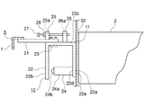
- the skirt guard switch device 12 has a flat plate-shaped connecting member 21, a bracket 22, a plurality of fixing bolts 23, a detection switch 24, a fixing piece 25, a movable piece 26, an adjusting bolt 27, and a nut 28.
- the connecting member 21 is fixed to the vertical member 7 by welding, for example. Further, the connecting member 21 projects horizontally from the vertical member 7 toward the carrier 1.
- the bracket 22 is fixed to the connecting member 21 by a plurality of fixing bolts 23. That is, the bracket 22 is fixed to the truss 5 via the connecting member 21. Further, the bracket 22 is arranged between the carrier 1 and the vertical member 7.
- the planar shape of the bracket 22 when fixed to the connecting member 21 is U-shaped.
- the bracket 22 has a first facing portion 22a, a second facing portion 22b, and a connecting portion 22c.
- the first facing portion 22a, the second facing portion 22b, and the connecting portion 22c are formed by bending a rectangular flat plate.
- the bracket 22 is made of the same metal as the skirt guard 11, for example, stainless steel.
- the shape of the first facing portion 22a, the shape of the second facing portion 22b, and the shape of the connecting portion 22c are rectangular flat plates, respectively.
- the first facing portion 22a and the second facing portion 22b project horizontally from the connecting portion 22c in the same direction.
- the first facing portion 22a and the second facing portion 22b face each other.
- the first facing portion 22a and the second facing portion 22b are parallel to each other and perpendicular to the connecting portion 22c.
- the first facing portion 22a has a facing surface 22d and an outer surface 22e.
- the facing surface 22d is a surface facing the second facing portion 22b.
- the outer side surface 22e is a surface opposite to the facing surface 22d.
- the outer surface 22e is in contact with the skirt guard 11.
- the skirt guard 11 is fixed to the outer side surface 22e, for example, by adhesion or welding. That is, the first facing portion 22a is overlapped and fixed on the skirt guard 11. Further, the first facing portion 22a can be deformed integrally with the skirt guard 11.
- the connecting portion 22c connects the first facing portion 22a and the second facing portion 22b. Further, the connecting portion 22c is fixed to the connecting member 21 by a plurality of fixing bolts 23. As a result, the connecting portion 22c is fixed to the truss 5.
- the connecting member 21 or the connecting portion 22c is provided with an elongated hole (not shown).
- a plurality of fixing bolts 23 are passed through the elongated holes. Therefore, the position of the connecting portion 22c with respect to the connecting member 21 can be adjusted in the width direction of the carrier 1 by loosening the plurality of fixing bolts 23.
- the detection switch 24 is supported by the bracket 22. Further, the detection switch 24 detects the deformation of the skirt guard 11 in the direction away from the carrier 1.
- the detection switch 24 has a switch main body 24a and an operation unit 24b.
- the base end portion of the switch body 24a is fixed to the first facing portion 22a.
- the operation unit 24b is provided at the tip of the switch body 24a. Further, the operation unit 24b faces the second facing unit 22b.
- the detection switch 24 is operated by the second facing portion 22b due to the deformation of the skirt guard 11.
- the skirt guard 11 bends in the direction away from the carrier 1. At this time, the first facing portion 22a bends integrally with the skirt guard 11.
- the connecting portion 22c since the connecting portion 22c is fixed to the connecting member 21, the second facing portion 22b does not move or deform. Therefore, when the first facing portion 22a bends, the detection switch 24 fixed to the first facing portion 22a approaches the second facing portion 22b. Then, when the amount of deflection of the first facing portion 22a exceeds the set value, the operating portion 24b is operated by the second facing portion 22b.
- the fixing piece 25 is fixed to the connecting member 21.
- the movable piece 26 is fixed to the connecting portion 22c. Further, the movable piece 26 faces the fixed piece 25.
- the adjusting bolt 27 penetrates the fixed piece 25 from the opposite side of the movable piece 26 and is screwed into the movable piece 26. That is, the adjusting bolt 27 is provided between the connecting member 21 and the bracket 22 via the fixed piece 25 and the movable piece 26.
- the fixing piece 25 is provided with a through hole 25a through which the adjusting bolt 27 is passed.
- the movable piece 26 is provided with a screw hole 26a into which the adjusting bolt 27 is screwed.
- the nut 28 is an end face of the fixed piece 25 and is in contact with the end face on the opposite side of the movable piece 26. An adjusting bolt 27 is screwed into the nut 28.
- the first facing portion 22a is overlapped and fixed on the skirt guard 11, and can be deformed integrally with the skirt guard 11.
- the second facing portion 22b faces the first facing portion 22a.
- the connecting portion 22c is fixed to the truss 5.
- the detection switch 24 is provided on the first facing portion 22a, and is operated by the second facing portion 22b due to the deformation of the skirt guard 11.
- bracket 22 can be fixed to the skirt guard 11 in advance at the factory, and the workability in the installation work of the escalator can be improved.
- the position of the connecting portion 22c with respect to the connecting member 21 can be adjusted in the width direction of the conveying body 1 by loosening the plurality of fixing bolts 23. Therefore, it is possible to easily adjust the gap between the skirt guard 11 and the carrier 1.
- adjusting bolt 27 is provided between the connecting member 21 and the bracket 22, it is possible to further easily adjust the gap between the skirt guard 11 and the carrier 1.
- the detection switch 24 may be provided on the second facing portion 22b. In this case, the detection switch 24 is operated by the first facing portion 22a.
- the position where the skirt guard switch device 12 is provided is not limited to the lower curved portion and the upper curved portion, and may be, for example, an intermediate inclined portion.
- the number of skirt guard switch devices 12 is not particularly limited.
- the passenger conveyor may be a moving walkway.
Landscapes
- Escalators And Moving Walkways (AREA)
Priority Applications (3)
| Application Number | Priority Date | Filing Date | Title |
|---|---|---|---|
| JP2022514873A JP7204994B2 (ja) | 2020-04-13 | 2020-04-13 | 乗客コンベア及びそのスカートガードスイッチ装置 |
| CN202080079998.2A CN115315405B (zh) | 2020-04-13 | 2020-04-13 | 乘客输送机及其围裙板开关装置 |
| PCT/JP2020/016239 WO2021210036A1 (ja) | 2020-04-13 | 2020-04-13 | 乗客コンベア及びそのスカートガードスイッチ装置 |
Applications Claiming Priority (1)
| Application Number | Priority Date | Filing Date | Title |
|---|---|---|---|
| PCT/JP2020/016239 WO2021210036A1 (ja) | 2020-04-13 | 2020-04-13 | 乗客コンベア及びそのスカートガードスイッチ装置 |
Publications (1)
| Publication Number | Publication Date |
|---|---|
| WO2021210036A1 true WO2021210036A1 (ja) | 2021-10-21 |
Family
ID=78084387
Family Applications (1)
| Application Number | Title | Priority Date | Filing Date |
|---|---|---|---|
| PCT/JP2020/016239 Ceased WO2021210036A1 (ja) | 2020-04-13 | 2020-04-13 | 乗客コンベア及びそのスカートガードスイッチ装置 |
Country Status (3)
| Country | Link |
|---|---|
| JP (1) | JP7204994B2 (https=) |
| CN (1) | CN115315405B (https=) |
| WO (1) | WO2021210036A1 (https=) |
Cited By (1)
| Publication number | Priority date | Publication date | Assignee | Title |
|---|---|---|---|---|
| WO2023203050A1 (de) * | 2022-04-21 | 2023-10-26 | Inventio Ag | Positionssensor für fahrtreppen und fahrsteige |
Citations (3)
| Publication number | Priority date | Publication date | Assignee | Title |
|---|---|---|---|---|
| JPS5997970U (ja) * | 1982-12-23 | 1984-07-03 | 株式会社東芝 | エスカレ−タのスカ−トガ−ド安全スイツチ |
| JPH0597373A (ja) * | 1991-10-04 | 1993-04-20 | Mitsubishi Electric Corp | マンコンベアの安全装置 |
| JP2016216148A (ja) * | 2015-05-15 | 2016-12-22 | 三菱電機株式会社 | 乗客コンベア |
Family Cites Families (4)
| Publication number | Priority date | Publication date | Assignee | Title |
|---|---|---|---|---|
| JPH07315747A (ja) * | 1994-05-31 | 1995-12-05 | Toshiba Corp | マンコンベアの安全装置 |
| JP2008201566A (ja) * | 2007-02-22 | 2008-09-04 | Mitsubishi Electric Building Techno Service Co Ltd | マンコンベア安全装置 |
| CN103010918B (zh) * | 2012-12-12 | 2015-05-27 | 成都市特种设备检验院 | 自动扶梯安全围裙板 |
| CN204549783U (zh) * | 2015-02-12 | 2015-08-12 | 江南嘉捷电梯股份有限公司 | 一种自动扶梯或自动人行道上的围裙保护装置 |
-
2020
- 2020-04-13 JP JP2022514873A patent/JP7204994B2/ja active Active
- 2020-04-13 CN CN202080079998.2A patent/CN115315405B/zh active Active
- 2020-04-13 WO PCT/JP2020/016239 patent/WO2021210036A1/ja not_active Ceased
Patent Citations (3)
| Publication number | Priority date | Publication date | Assignee | Title |
|---|---|---|---|---|
| JPS5997970U (ja) * | 1982-12-23 | 1984-07-03 | 株式会社東芝 | エスカレ−タのスカ−トガ−ド安全スイツチ |
| JPH0597373A (ja) * | 1991-10-04 | 1993-04-20 | Mitsubishi Electric Corp | マンコンベアの安全装置 |
| JP2016216148A (ja) * | 2015-05-15 | 2016-12-22 | 三菱電機株式会社 | 乗客コンベア |
Cited By (1)
| Publication number | Priority date | Publication date | Assignee | Title |
|---|---|---|---|---|
| WO2023203050A1 (de) * | 2022-04-21 | 2023-10-26 | Inventio Ag | Positionssensor für fahrtreppen und fahrsteige |
Also Published As
| Publication number | Publication date |
|---|---|
| CN115315405A (zh) | 2022-11-08 |
| CN115315405B (zh) | 2025-11-14 |
| JPWO2021210036A1 (https=) | 2021-10-21 |
| JP7204994B2 (ja) | 2023-01-16 |
Similar Documents
| Publication | Publication Date | Title |
|---|---|---|
| KR20060058144A (ko) | 승객용 컨베이어 | |
| WO2021210036A1 (ja) | 乗客コンベア及びそのスカートガードスイッチ装置 | |
| JP5114062B2 (ja) | 乗客コンベアの移動手摺り案内装置 | |
| CN100400407C (zh) | 客运输送机 | |
| JP2004196443A (ja) | 乗客コンベア | |
| JP2016166061A (ja) | 延設部材とそれを用いた乗客コンベア | |
| JP2007161447A (ja) | 乗客コンベアのスカートガード装置 | |
| JP2018108867A (ja) | 乗客コンベアの異常検出装置 | |
| JP6329877B2 (ja) | 乗客コンベア | |
| JP7118252B2 (ja) | 乗客コンベヤのトラス | |
| JP2008068961A (ja) | エレベータ用ガイドレールの継目板 | |
| JP2011219228A (ja) | 乗客コンベアの乗降部床装置 | |
| JP6353819B2 (ja) | 乗客コンベア | |
| EP0608125B1 (en) | Escalator balustrade skirt panel | |
| JP2783137B2 (ja) | 乗客コンベヤの乗降口装置 | |
| JP6367403B1 (ja) | 乗客コンベア | |
| JP6896169B2 (ja) | 乗客コンベアのコムプレート移動検出装置 | |
| JP7518028B2 (ja) | 乗客コンベア | |
| US9457996B2 (en) | Balustrade support for an escalator or a moving walkway | |
| JPWO2020230299A1 (ja) | 乗客コンベアの乗降口安全装置 | |
| JP7248193B2 (ja) | 乗客コンベアの床板、および乗客コンベア | |
| JP2007176692A (ja) | 乗客コンベアの欄干構造 | |
| JP4246936B2 (ja) | 乗客コンベアの欄干構造 | |
| US10227214B1 (en) | Passenger conveyor skirt panel positioning assembly | |
| JP2009190871A (ja) | 乗客コンベアの目地部材 |
Legal Events
| Date | Code | Title | Description |
|---|---|---|---|
| 121 | Ep: the epo has been informed by wipo that ep was designated in this application |
Ref document number: 20931689 Country of ref document: EP Kind code of ref document: A1 |
|
| ENP | Entry into the national phase |
Ref document number: 2022514873 Country of ref document: JP Kind code of ref document: A |
|
| WWE | Wipo information: entry into national phase |
Ref document number: 202080079998.2 Country of ref document: CN |
|
| NENP | Non-entry into the national phase |
Ref country code: DE |
|
| 122 | Ep: pct application non-entry in european phase |
Ref document number: 20931689 Country of ref document: EP Kind code of ref document: A1 |