WO2021200289A1 - 情報処理装置、放射線画像撮影装置、情報処理方法、及び情報処理プログラム - Google Patents
情報処理装置、放射線画像撮影装置、情報処理方法、及び情報処理プログラム Download PDFInfo
- Publication number
- WO2021200289A1 WO2021200289A1 PCT/JP2021/011505 JP2021011505W WO2021200289A1 WO 2021200289 A1 WO2021200289 A1 WO 2021200289A1 JP 2021011505 W JP2021011505 W JP 2021011505W WO 2021200289 A1 WO2021200289 A1 WO 2021200289A1
- Authority
- WO
- WIPO (PCT)
- Prior art keywords
- image
- information processing
- visible light
- radiation
- irradiation
- Prior art date
- Legal status (The legal status is an assumption and is not a legal conclusion. Google has not performed a legal analysis and makes no representation as to the accuracy of the status listed.)
- Ceased
Links
Images


Classifications
-
- G—PHYSICS
- G06—COMPUTING OR CALCULATING; COUNTING
- G06T—IMAGE DATA PROCESSING OR GENERATION, IN GENERAL
- G06T7/00—Image analysis
- G06T7/0002—Inspection of images, e.g. flaw detection
- G06T7/0012—Biomedical image inspection
- G06T7/0014—Biomedical image inspection using an image reference approach
-
- A—HUMAN NECESSITIES
- A61—MEDICAL OR VETERINARY SCIENCE; HYGIENE
- A61B—DIAGNOSIS; SURGERY; IDENTIFICATION
- A61B6/00—Apparatus or devices for radiation diagnosis; Apparatus or devices for radiation diagnosis combined with radiation therapy equipment
- A61B6/04—Positioning of patients; Tiltable beds or the like
- A61B6/0407—Supports, e.g. tables or beds, for the body or parts of the body
- A61B6/0414—Supports, e.g. tables or beds, for the body or parts of the body with compression means
-
- A—HUMAN NECESSITIES
- A61—MEDICAL OR VETERINARY SCIENCE; HYGIENE
- A61B—DIAGNOSIS; SURGERY; IDENTIFICATION
- A61B6/00—Apparatus or devices for radiation diagnosis; Apparatus or devices for radiation diagnosis combined with radiation therapy equipment
- A61B6/08—Auxiliary means for directing the radiation beam to a particular spot, e.g. using light beams
-
- A—HUMAN NECESSITIES
- A61—MEDICAL OR VETERINARY SCIENCE; HYGIENE
- A61B—DIAGNOSIS; SURGERY; IDENTIFICATION
- A61B6/00—Apparatus or devices for radiation diagnosis; Apparatus or devices for radiation diagnosis combined with radiation therapy equipment
- A61B6/10—Safety means specially adapted therefor
- A61B6/107—Protection against radiation, e.g. shielding
-
- A—HUMAN NECESSITIES
- A61—MEDICAL OR VETERINARY SCIENCE; HYGIENE
- A61B—DIAGNOSIS; SURGERY; IDENTIFICATION
- A61B6/00—Apparatus or devices for radiation diagnosis; Apparatus or devices for radiation diagnosis combined with radiation therapy equipment
- A61B6/44—Constructional features of apparatus for radiation diagnosis
- A61B6/4417—Constructional features of apparatus for radiation diagnosis related to combined acquisition of different diagnostic modalities
-
- A—HUMAN NECESSITIES
- A61—MEDICAL OR VETERINARY SCIENCE; HYGIENE
- A61B—DIAGNOSIS; SURGERY; IDENTIFICATION
- A61B6/00—Apparatus or devices for radiation diagnosis; Apparatus or devices for radiation diagnosis combined with radiation therapy equipment
- A61B6/50—Apparatus or devices for radiation diagnosis; Apparatus or devices for radiation diagnosis combined with radiation therapy equipment specially adapted for specific body parts; specially adapted for specific clinical applications
- A61B6/502—Apparatus or devices for radiation diagnosis; Apparatus or devices for radiation diagnosis combined with radiation therapy equipment specially adapted for specific body parts; specially adapted for specific clinical applications for diagnosis of breast, i.e. mammography
-
- A—HUMAN NECESSITIES
- A61—MEDICAL OR VETERINARY SCIENCE; HYGIENE
- A61B—DIAGNOSIS; SURGERY; IDENTIFICATION
- A61B6/00—Apparatus or devices for radiation diagnosis; Apparatus or devices for radiation diagnosis combined with radiation therapy equipment
- A61B6/54—Control of apparatus or devices for radiation diagnosis
- A61B6/542—Control of apparatus or devices for radiation diagnosis involving control of exposure
-
- G—PHYSICS
- G06—COMPUTING OR CALCULATING; COUNTING
- G06T—IMAGE DATA PROCESSING OR GENERATION, IN GENERAL
- G06T7/00—Image analysis
- G06T7/10—Segmentation; Edge detection
- G06T7/13—Edge detection
-
- G—PHYSICS
- G06—COMPUTING OR CALCULATING; COUNTING
- G06T—IMAGE DATA PROCESSING OR GENERATION, IN GENERAL
- G06T7/00—Image analysis
- G06T7/90—Determination of colour characteristics
-
- G—PHYSICS
- G06—COMPUTING OR CALCULATING; COUNTING
- G06V—IMAGE OR VIDEO RECOGNITION OR UNDERSTANDING
- G06V10/00—Arrangements for image or video recognition or understanding
- G06V10/20—Image preprocessing
- G06V10/22—Image preprocessing by selection of a specific region containing or referencing a pattern; Locating or processing of specific regions to guide the detection or recognition
-
- G—PHYSICS
- G06—COMPUTING OR CALCULATING; COUNTING
- G06T—IMAGE DATA PROCESSING OR GENERATION, IN GENERAL
- G06T2207/00—Indexing scheme for image analysis or image enhancement
- G06T2207/10—Image acquisition modality
- G06T2207/10024—Color image
-
- G—PHYSICS
- G06—COMPUTING OR CALCULATING; COUNTING
- G06T—IMAGE DATA PROCESSING OR GENERATION, IN GENERAL
- G06T2207/00—Indexing scheme for image analysis or image enhancement
- G06T2207/10—Image acquisition modality
- G06T2207/10028—Range image; Depth image; 3D point clouds
-
- G—PHYSICS
- G06—COMPUTING OR CALCULATING; COUNTING
- G06T—IMAGE DATA PROCESSING OR GENERATION, IN GENERAL
- G06T2207/00—Indexing scheme for image analysis or image enhancement
- G06T2207/10—Image acquisition modality
- G06T2207/10064—Fluorescence image
-
- G—PHYSICS
- G06—COMPUTING OR CALCULATING; COUNTING
- G06T—IMAGE DATA PROCESSING OR GENERATION, IN GENERAL
- G06T2207/00—Indexing scheme for image analysis or image enhancement
- G06T2207/10—Image acquisition modality
- G06T2207/10116—X-ray image
-
- G—PHYSICS
- G06—COMPUTING OR CALCULATING; COUNTING
- G06T—IMAGE DATA PROCESSING OR GENERATION, IN GENERAL
- G06T2207/00—Indexing scheme for image analysis or image enhancement
- G06T2207/10—Image acquisition modality
- G06T2207/10116—X-ray image
- G06T2207/10121—Fluoroscopy
-
- G—PHYSICS
- G06—COMPUTING OR CALCULATING; COUNTING
- G06T—IMAGE DATA PROCESSING OR GENERATION, IN GENERAL
- G06T2207/00—Indexing scheme for image analysis or image enhancement
- G06T2207/30—Subject of image; Context of image processing
- G06T2207/30004—Biomedical image processing
- G06T2207/30068—Mammography; Breast
-
- G—PHYSICS
- G06—COMPUTING OR CALCULATING; COUNTING
- G06T—IMAGE DATA PROCESSING OR GENERATION, IN GENERAL
- G06T2207/00—Indexing scheme for image analysis or image enhancement
- G06T2207/30—Subject of image; Context of image processing
- G06T2207/30168—Image quality inspection
-
- G—PHYSICS
- G06—COMPUTING OR CALCULATING; COUNTING
- G06T—IMAGE DATA PROCESSING OR GENERATION, IN GENERAL
- G06T2207/00—Indexing scheme for image analysis or image enhancement
- G06T2207/30—Subject of image; Context of image processing
- G06T2207/30196—Human being; Person
-
- G—PHYSICS
- G06—COMPUTING OR CALCULATING; COUNTING
- G06T—IMAGE DATA PROCESSING OR GENERATION, IN GENERAL
- G06T2207/00—Indexing scheme for image analysis or image enhancement
- G06T2207/30—Subject of image; Context of image processing
- G06T2207/30204—Marker
-
- G—PHYSICS
- G06—COMPUTING OR CALCULATING; COUNTING
- G06V—IMAGE OR VIDEO RECOGNITION OR UNDERSTANDING
- G06V2201/00—Indexing scheme relating to image or video recognition or understanding
- G06V2201/03—Recognition of patterns in medical or anatomical images
Definitions
- This disclosure relates to an information processing device, a radiographic imaging device, an information processing method, and an information processing program.
- a radiation image When a radiation image is taken by a radiation image capturing device, when the radiation image is taken in a state where a foreign substance such as a part other than the object to be photographed of the subject has invaded the irradiation area of the radiation emitted from the radiation source, the radiation is emitted. It may be necessary to retake the image. Therefore, in taking a radiation image, the user confirms the irradiation range of the radiation indicated by the visible light to confirm whether or not a foreign substance is present in the irradiation region of the radiation. For example, Japanese Patent Application Laid-Open No. 2018-157941 describes a technique for suggesting an irradiation field of radiation by visible light.
- the detection of foreign matter that has invaded the radiation irradiation area has been conventionally performed, but the conventional technology may not be sufficient to detect the foreign matter that has invaded the radiation irradiation area. be.
- the subject may move and a part of the subject other than the imaging target may invade the irradiation area.
- the conventional technique cannot cope with such a case, and re-shooting may be required.
- This disclosure has been made in consideration of the above circumstances, and is an information processing device, an information processing method, and an information processing program capable of appropriately detecting the presence or absence of a foreign substance other than the imaging target in the irradiation region of radiation. I will provide a.
- the information processing apparatus of the first aspect of the present disclosure includes at least one processor and a memory for storing instructions that can be executed by the processor, and the processor is used for an imaging object imaged by the radiation imaging apparatus.
- An image taken by an imaging device whose area including the irradiation area, which is the space where radiation is emitted from the radiation source, is an imageable area is acquired, and the presence or absence of foreign matter other than the object to be imaged in the irradiation area is obtained based on the image. Is detected.
- the processor acquires information representing an irradiation region and detects the presence or absence of a foreign substance in the irradiation region represented by the information. ..
- the information processing apparatus of the third aspect of the present disclosure is the information processing apparatus of the first aspect or the second aspect, in which the processor uses the space between the imaging target and the radiation source as the detection region in the irradiation region. Derived and detect the presence or absence of foreign matter in the derived detection area.
- the information processing apparatus is the information processing apparatus according to the third aspect. Of these, it is the space between the compression member that presses the breast and the radiation source.
- the information processing device of the fifth aspect of the present disclosure is the information processing device of the third aspect or the fourth aspect. It is a photographing device.
- the processor detects the presence or absence of foreign matter in the detection area by using the image corresponding to the detection area in the distance image.
- the information processing apparatus is the information processing apparatus according to the sixth aspect, wherein the processor is a distance between the photographing apparatus derived based on the position of the detection region and each position in the detection region. The presence or absence of foreign matter in the detection area is detected based on the distance between the photographing device and the photographing target represented by the image corresponding to the detection area in the distance image.
- the information processing device is the information processing device according to any one of the fifth to seventh aspects, and the distance imaging device is a distance using a TOF (Time Of Flight) method. Take an image.
- TOF Time Of Flight
- the information processing device is the information processing device according to any one of the first to fourth aspects, wherein the photographing device captures a visible light image to be photographed as a captured image. It is an optical image capturing device.
- the information processing apparatus is the information processing apparatus according to the first aspect. Is a visible light image capturing device that captures a visible light image to be captured as a captured image, and a processor detects the presence or absence of foreign matter based on the lack of an image of a compression member in the captured image.
- the processor detects the presence or absence of a foreign substance based on the chipping of the subject on the breast in the image of the compression member.
- the information processing device of the twelfth aspect of the present disclosure is the information processing device of the tenth aspect or the eleventh aspect, and the processor uses an image of an edge portion of the compression member as an image of the compression member.
- the processor acquires the compression member information indicating the type of the compression member, and includes the compression member information in the captured image based on the compression member information. Estimate at least one of the position and size of the image of the edge portion to be processed.
- the information processing apparatus is the information processing apparatus according to the twelfth or thirteenth aspect.
- the color is different from at least one of the imaging tables to be processed, and the processor extracts an image of the edge portion of the compression member from the captured image based on the color of the edge portion.
- the information processing apparatus is the information processing apparatus according to the twelfth aspect or the thirteenth aspect.
- the processing is performed so as to be distinguishable from the above, and the processor extracts the image of the edge portion from the captured image.
- the edge portion of the compression member is emphasized by at least one of the phosphorescent material and the fluorescent material.
- the information processing apparatus is the information processing apparatus according to any one of the tenth to sixteenth aspects.
- the presence or absence of foreign matter is detected based on the chipping of the image.
- the information processing apparatus is the information processing apparatus according to the first aspect. Is a visible light image capturing device that captures a visible light image obtained by capturing a projected image projected by an image projection device on an irradiation surface of a compression member that is irradiated with radiation as a captured image.
- the information processing apparatus of the 19th aspect of the present disclosure is the information processing apparatus of the 18th aspect, in which the projected image projected on the irradiation surface is projected within the range of the irradiation field of radiation.
- the projected image projected on the irradiation surface causes the range of the irradiation field of radiation to be projected by visible light. It is projected within the range of the radiation field by the irradiation field projection device without irradiating visible light.
- the information processing apparatus is the information processing apparatus according to any one of the 18th to 20th aspects. Based on this, the presence or absence of foreign matter is detected.
- the information processing apparatus is based on the comparison result of comparing the projected image and the captured image in the information processing apparatus according to any one of the 18th to 21st aspects. To detect the presence or absence of foreign matter.
- the information processing apparatus is the information processing apparatus according to any one of the 18th to 21st aspects, wherein the processor controls to project a projected image onto a region including an irradiation field of radiation. Is performed on the image projection device.
- the processor derives the size and position of the irradiation field on the irradiation surface of the compression member according to the height of the compression member. Then, control is performed to project the projected image according to the size and position of the derived irradiation field.
- the information processing apparatus is the information processing apparatus according to the first aspect. Is a visible light image capturing device that captures a state in which the range of the irradiation field is projected on the compression member as a captured image by the irradiation field projection device that projects the range of the irradiation field of radiation with visible light.
- the information processing apparatus according to the 26th aspect of the present disclosure is the information processing apparatus according to any one of the first to the twenty-fifth aspects. Irradiation is prohibited.
- the processor when the processor detects the presence of a foreign substance, the processor outputs a warning regarding the foreign substance. do.
- the information processing apparatus is the information processing apparatus according to any one of the first to 27th aspects.
- the combined imageable area of the entire plurality of imaging devices includes the irradiation area.
- the radiographic imaging apparatus includes the information processing apparatus of the present disclosure and the imaging apparatus value.
- the information processing method includes an irradiation region which is a space in which radiation is emitted from a radiation source to an imaged object photographed by a radiation imaging apparatus.
- This is a method for a computer to acquire a photographed image taken by a photographing apparatus having an area as a photographable area and to detect the presence or absence of foreign matter other than the imaged object in the irradiated area based on the photographed image.
- the information processing program is an imaging apparatus in which an region including an irradiation region, which is a space in which radiation is emitted from a radiation source to an imaging target photographed by the radiation imaging apparatus, is an imageable area. This is for causing a computer to perform a process of acquiring a photographed image photographed by the above and detecting the presence or absence of a foreign substance other than the imaged object in the irradiation area based on the photographed image.
- FIG. 1 shows a configuration diagram showing an example of the overall configuration of the radiation imaging system 1 of the present embodiment.
- the radiographic imaging system 1 of the present embodiment includes a mammography apparatus 10 and a console 12.
- the mammography apparatus 10 of the present embodiment is an example of the radiographic imaging apparatus of the present disclosure.
- the console 12 of the present embodiment is an example of the information processing apparatus of the present disclosure.
- FIG. 2 shows a side view showing an example of the appearance of the mammography apparatus 10 of the present embodiment. Note that FIG. 2 shows an example of the appearance when the mammography apparatus 10 is viewed from the right side of the subject.
- the mammography apparatus 10 of the present embodiment is an apparatus that takes a breast of a subject as a subject and irradiates the breast with radiation R (for example, X-ray) to take a radiographic image of the breast.
- the mammography apparatus 10 photographs the breast of the subject not only when the subject is standing (standing position) but also when the subject is sitting on a chair (including a wheelchair) or the like (sitting state). It may be a device that does.
- the mammography apparatus 10 of the present embodiment includes a control unit 20, a storage unit 22, and an I / F (Interface) unit 24 inside the photographing table 30.
- the control unit 20 controls the overall operation of the mammography apparatus 10 according to the control of the console 12.
- the control unit 20 includes a CPU (Central Processing Unit), a ROM (Read Only Memory), and a RAM (Random Access Memory), all of which are not shown.
- the ROM stores in advance various programs and the like, which are executed by the CPU and include an imaging processing program for controlling the imaging of radiographic images.
- the RAM temporarily stores various data.
- the storage unit 22 stores image data of a radiation image taken by the radiation detector 28, various other information, and the like. Specific examples of the storage unit 22 include HDD (Hard Disk Drive) and SSD (Solid State Drive).
- the I / F unit 24 communicates various information with the console 12 by wireless communication or wired communication.
- the image data of the radiation image taken by the radiation detector 28 by the mammography apparatus 10 is transmitted to the console 12 via the I / F unit 24 by wireless communication or wired communication.
- the operation unit 26 is provided as a plurality of switches on, for example, the imaging table 30 of the mammography apparatus 10.
- the operation unit 26 may be provided as a touch panel type switch, or may be provided as a foot switch operated by the user with his / her foot.
- the radiation detector 28 detects the radiation R that has passed through the breast, which is the subject. As shown in FIG. 2, the radiation detector 28 is arranged inside the photographing table 30. In the mammography apparatus 10 of the present embodiment, when imaging is performed, the breast of the subject is positioned on the imaging surface 30A of the imaging table 30 by a user such as a doctor or a technician.
- the radiation detector 28 detects the radiation R transmitted through the subject's breast and the imaging table 30, generates a radiation image based on the detected radiation R, and outputs image data representing the generated radiation image.
- the type of the radiation detector 28 of the present embodiment is not particularly limited, and may be, for example, an indirect conversion type radiation detector that converts radiation R into light and converts the converted light into electric charge, or radiation.
- a direct conversion type radiation detector that directly converts R into an electric charge may be used.
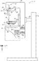
- the radiation irradiation unit 37 includes a radiation source 37R having a radiation tube (not shown) that irradiates the imaging table 30 with radiation R. Further, the radiation irradiation unit 37 includes a collimator 33. By controlling the collimator 33 by the control unit 20, the irradiation region 70 of the radiation R is set as shown in FIG. 3, and the irradiation field 71 of the radiation R on the imaging surface 30A of the imaging table 30 is defined.
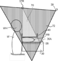
- FIG. 3 shows an example of the irradiation region 70 of the radiation R irradiated from the radiation source 37R in a state where the breast WB of the subject W photographed by the mammography apparatus 10 is compressed by the compression plate 40.
- the irradiation region 70 is a space in which the radiation R is irradiated from the radiation source 37R to the imaged object to be imaged by the mammography apparatus 10.
- the size and shape of the irradiation field 71 of the present embodiment are determined according to the size of the imaging surface (not shown) of the radiation detector 28, the size of the breast WB to be imaged, and the like, and the irradiation field 71 of the irradiation field 71.
- the control unit 20 controls the collimator 33 according to the size and shape.
- the shape of the irradiation field 71 is rectangular.
- the irradiation region 70 of the present embodiment is a quadrangular pyramid-shaped region having the focal point of the radiation tube (not shown) included in the radiation source 37R as the apex and the irradiation field 71 as the bottom surface.
- the imaging target in the present embodiment is the breast WB of the subject, but the imaging target is not limited to the breast WB, and includes those approved to be imaged on a radiographic image such as a marker.
- the compression plate 40 or the like which is recognized to be arranged in the imaging region of the radiographic image in the radiographic image capturing, is also regarded as an imaging target.
- an object other than the object to be imaged that invades the irradiation area 70 is referred to as a “foreign substance”.
- the foreign matter include a head WH of the subject W, a hand (not shown), and a foreign object other than the subject W.
- the radiation irradiation unit 37 is provided on the arm unit 32 together with the photographing table 30 and the compression unit 36.
- a face guard 38 for protecting the subject from the radiation R emitted from the radiation source 37R can be attached and detached at a position close to the subject of the arm portion 32 below the radiation irradiation portion 37. It is attached.
- a TOF (Time of Flight) camera 39 is provided at a position away from the subject of the arm portion 32, which is below the irradiation unit 37.
- the TOF camera 39 is a camera that uses the TOF method to capture a distance image representing a distance to a subject to be imaged.
- the TOF camera 39 of the present embodiment is an example of the photographing device and the distance image capturing device of the present disclosure. Specifically, the TOF camera 39 takes a picture with the TOF camera 39 based on the time until the object to be photographed is irradiated with light such as infrared rays and the reflected light is received, or the phase change between the emitted light and the received light. Measure the distance to the subject.
- the distance image captured by the TOF camera 39 has distance information representing the distance between the TOF camera 39 and the imaging target for each pixel.
- the distance image is an image from which the distance to the shooting target can be derived.
- the TOF camera 39 of the present embodiment is arranged so that the photographable area 72 includes the entire irradiation area 70. Therefore, the distance image taken by the TOF camera 39 includes an image corresponding to the irradiation region 70.
- the photographable area 72 is defined by design.
- the mammography apparatus 10 of the present embodiment includes an arm portion 32, a base 34, and a shaft portion 35.
- the arm portion 32 is movably held in the vertical direction (Z-axis direction) by the base 34.
- the shaft portion 35 connects the arm portion 32 to the base 34.
- the arm portion 32 is rotatable relative to the base 34 with the shaft portion 35 as the rotation axis.
- the arm portion 32 and the compression unit 36 can rotate separately with respect to the base 34 with the shaft portion 35 as the rotation axis.
- gears (not shown) are provided on the shaft portion 35, the arm portion 32, and the compression unit 36, respectively, and the arm portion 32 and the compression unit 36 are switched by switching between the meshed state and the non-engaged state of the gears.
- Each of the above is connected to the shaft portion 35.
- One or both of the arm portion 32 and the compression unit 36 connected to the shaft portion 35 rotate integrally with the shaft portion 35.
- the compression unit 36 is provided with a compression plate drive unit (not shown) that moves the compression plate 40 in the vertical direction (Z-axis direction).
- the compression plate 40 of the present embodiment has a function of pressing the breast of the subject.
- the support portion 46 of the compression plate 40 is detachably attached to the compression plate drive portion, moves in the vertical direction (Z-axis direction) by the compression plate drive portion, and presses the breast of the subject with the imaging table 30. ..
- the compression plate 40 of the present embodiment is an example of the compression member of the present disclosure.
- the compression plate 40 of the present embodiment includes a bottom portion 43, a wall portion 44, and a support portion 46, and the bottom portion 43 in contact with the breast of the subject is surrounded by the wall portion 44 in a cross section.
- the shape is concave.
- the compression plate 40 is not limited to the one that presses the entire breast, but may be the one that presses a part of the breast. In other words, the compression plate 40, which is smaller than the breast, may be used.
- a compression plate 40 for example, a compression plate 40 used for so-called spot imaging, which captures a radiographic image of only a region where a lesion exists, is known.
- the other type of compression plate 40 include a compression plate according to the size of the breast, a compression plate for axillary imaging, a compression plate for magnified imaging, and the like.
- the compression plate 40 is not limited to one using a plate-shaped member, and may be, for example, one using a film-shaped member.
- the console 12 of the present embodiment is performed by the user by the operation unit 56 and the like, and the shooting order and various information acquired from the RIS (Radiology Information System) 2 and the like via the wireless communication LAN (Local Area Network) and the like. It has a function of controlling the mammography apparatus 10 by using instructions and the like.
- RIS Radiology Information System
- LAN Local Area Network
- the console 12 of this embodiment is, for example, a server computer. As shown in FIG. 5, the console 12 includes a control unit 50, a storage unit 52, an I / F unit 54, an operation unit 56, and a display unit 58.
- the control unit 50, the storage unit 52, the I / F unit 54, the operation unit 56, and the display unit 58 are connected to each other via a bus 59 such as a system bus or a control bus so that various information can be exchanged.
- the control unit 50 of this embodiment controls the entire operation of the console 12.
- the control unit 50 includes a CPU 50A, a ROM 50B, and a RAM 50C.
- Various programs including the foreign matter detection processing program 51, which are executed by the CPU 50A, are stored in the ROM 50B in advance.
- the RAM 50C temporarily stores various data.
- the CPU 50A of the present embodiment is an example of the processor of the present disclosure
- the ROM 50B of the present embodiment is an example of the memory of the present disclosure.
- the foreign matter detection processing program 51 of the present embodiment is an example of the information processing program of the present disclosure.
- the storage unit 52 stores image data of a radiation image taken by the mammography apparatus 10 and various other information. Specific examples of the storage unit 52 include HDDs and SSDs.
- the operation unit 56 is used for the user to input instructions and various information related to taking a radiation image including an irradiation instruction of radiation R.
- the operation unit 56 is not particularly limited, and examples thereof include various switches, a touch panel, a touch pen, and a mouse.
- the display unit 58 displays various information.
- the operation unit 56 and the display unit 58 may be integrated into a touch panel display.
- the I / F unit 54 communicates various information with the mammography device 10 and the RIS2 by wireless communication or wired communication.
- the image data of the radiographic image taken by the mammography apparatus 10 is received by the console 12 from the mammography apparatus 10 by wireless communication or wired communication via the I / F unit 54.
- FIG. 6 shows a functional block diagram of an example of the functional configuration of the console 12 of the present embodiment.
- the console 12 includes a first acquisition unit 60, a second acquisition unit 62, and a detection unit 64.
- the CPU 50A of the control unit 50 executes the foreign matter detection processing program 51 stored in the ROM 50B, so that the CPU 50A detects the first acquisition unit 60, the second acquisition unit 62, and the detection unit 12. It functions as a unit 64.
- the first acquisition unit 60 has a function of acquiring information representing the irradiation area 70.
- the method by which the first acquisition unit 60 acquires the information representing the irradiation region 70 is not limited.
- the irradiation region 70 is determined according to the setting of the collimator 33 and the distance between the radiation source 37R and the imaging surface 30A of the imaging table 30.
- the setting of the collimator 33 and the distance between the radiation source 37R and the imaging surface 30A can be grasped by the mammography apparatus 10. Therefore, for example, first, the control unit 20 of the mammography apparatus 10 derives the irradiation region 70 based on the setting of the collimator 33 and the distance between the radiation source 37R and the imaging surface 30A.
- the first acquisition unit 60 may acquire the information representing the irradiation region 70 derived by the control unit 20 from the mammography apparatus 10.
- the console 12 acquires information indicating the setting of the collimator 33 and information indicating the distance between the radiation source 37R and the imaging surface 30A, and the console 12 uses the acquired information.
- the information representing the irradiation region 70 may be derived within the inside, and the first acquisition unit 60 may acquire the information representing the derived irradiation region 70.
- the information representing the irradiation area 70 acquired by the first acquisition unit 60 is output to the detection unit 64.
- the second acquisition unit 62 has a function of acquiring a distance image taken by the TOF camera 39.
- the second acquisition unit 62 of the present embodiment acquires image data representing a distance image taken by the TOF camera 39 from the TOF camera 39 via the I / F unit 24 and the I / F unit 54.
- the distance image acquired by the second acquisition unit 62 is output to the detection unit 64.
- the detection unit 64 has a function of detecting the presence or absence of foreign matter other than the image to be photographed in the irradiation area 70 based on the distance image.
- the detection unit 64 of the present embodiment derives the space between the imaging target and the radiation source 37R as the detection region 74 in the irradiation region 70, and the foreign matter in the derived detection region 74 is derived. Detects the presence or absence of.
- the detection region 74 of the present embodiment is the space from the upper surface (the surface on the radiation source 37R side) of the bottom 43 of the compression plate 40 to the radiation source 37R in the irradiation region 70. Is.
- the detection region 74 is determined according to the height H of the breast WB in a state of being compressed by the compression plate 40, the thickness of the bottom 43 of the compression plate 40, and the irradiation region 70.
- the detection region 74 of the present embodiment is determined by the height H of the breast WB in the state of being compressed by the compression plate 40, the size of the detection region 74 changes depending on the breast WB and the compression state thereof.
- the thickness of the bottom portion 43 is relatively thin, so that the thickness of the bottom portion 43 is ignored for convenience.
- the detection unit 64 of the present embodiment first acquires the thickness H of the breast WB in a state of being compressed by the compression plate 40.
- the method by which the detection unit 64 acquires the thickness H of the breast WB is not limited.
- a detection unit for detecting the movement amount of the compression plate 40 by the compression plate drive unit (not shown) provided in the compression unit 36 of the compression plate 40 is provided, and the movement amount of the compression plate 40 detected by this detection unit is provided.
- the thickness of the breast WB derived from the above may be acquired by the detection unit 64.
- the mammography apparatus 10 or the like is provided with a sensor or the like for detecting the height from the imaging surface 30A to the compression plate 40, that is, the thickness H of the breast WB, and the thickness H detected by this sensor is detected by the detection unit 64. May be the form acquired by.
- a marker or the like is provided in an area that does not overlap with the breast WB, such as the end of the compression plate 40, and the distance between the TOF camera 39 and the marker is measured based on the image of the marker reflected in the distance image, and the TOF camera 39 is used.
- the thickness H of the breast WB may be obtained by subtracting the distance between the TOF camera 39 and the marker from the distance between the image and the imaging surface 30A.
- the detection unit 64 derives the distance between the radiation source 37R and the bottom 43 by subtracting the thickness H of the breast WB from the distance between the radiation source 37R and the imaging surface 30A. Further, the detection unit 64 extracts a quadrangular pyramid having the apex of the irradiation region 70 as the radiation source 37R, the bottom portion 43 as the bottom surface, and the length of the perpendicular line as the distance between the radiation source 37R and the bottom portion 43.
- the detection region 74 is derived.
- the detection unit 64 corresponds to the distance between each position in the detection area 74 derived based on the position of the detection area 74 and the TOF camera 39, and the detection area 74 in the distance image acquired from the TOF camera 39.
- the presence or absence of foreign matter in the detection region 74 is detected based on the image to be used.
- the distance between the position in the detection area 74 and the TOF camera 39 can be obtained. More specifically, it is possible to obtain a pixel value (hereinafter, referred to as a pixel value of the detection area 74) when the position in the detection area 74 is represented by a distance image.
- the pixel value of the pixel representing the distance to the object in the distance image is any of the pixel values of each position in the detection area 74.
- FIG. 7B shows an example of a state in which the head WH of the subject W has invaded the detection region 74 as a foreign substance.
- the pixel value of the image corresponding to the detection area 74 in the distance image of the TOF camera 39 is the pixel value reflecting the distance measured by the infrared rays reflected by the head WH in the detection area 74. It becomes. Therefore, the detection unit 64 compares the pixel value of the image corresponding to the detection area 74 in the distance image acquired from the TOF camera 39 with the pixel value of each position in the detection area 74.
- the detection unit 64 determines that there is a foreign substance in the detection area 74. In this case, the detection unit 64 outputs a detection result indicating that there is a foreign substance.
- the detection unit 64 has a foreign object in the detection area 74. Judge that there is no. In the present embodiment, when it is determined that there is no foreign matter in the detection area 74, the detection unit 64 does not output the detection result, but unlike the present embodiment, even if the detection result indicating that there is no foreign matter is output. good.
- the CPU 50A of the control unit 50 executes the foreign matter detection processing program 51 stored in the ROM 50B to execute the foreign matter detection processing shown in FIG. 8 as an example.
- FIG. 8 shows a flowchart showing an example of the flow of the foreign matter detection process executed on the console 12 of the present embodiment.
- the timing at which the CPU 50A executes the foreign matter detection process is not limited and can be any timing, for example, the timing at which the movement of the compression plate 40 is stopped, the timing at which the irradiation instruction of the radiation R is received, and the like. Can be mentioned.
- step S100 of FIG. 8 the first acquisition unit 60 acquires information representing the irradiation region 70 as described above.
- the detection unit 64 acquires the thickness H of the breast WB as described above. Further, in the next step S104, the detection unit 64 derives the detection region 74 based on the information representing the irradiation region 70 and the thickness H of the breast WB, as described above.
- the detection unit 64 converts the distance from the TOF camera 39 to each position of the detection area 74 into the pixel value of the distance image. Specifically, the distance between the TOF camera 39 and each position in the detection area 74 is converted into a pixel value of a distance image to derive a pixel value of each position in the detection area 74.
- the second acquisition unit 62 acquires a distance image from the TOF camera 39 as described above.
- the detection unit 64 compares the pixel value of the image corresponding to the detection area 74 in the distance image acquired from the TOF camera 39 with the pixel value of each position of the detection area 74. In the next step S112, the detection unit 64 determines whether or not there is a foreign substance in the detection area 74. As described above, when the pixel value of the image corresponding to the detection area 74 in the distance image is any of the pixel values of each position of the detection area 74, the detection unit 64 determines that there is a foreign substance in the detection area 74. to decide. When the detection unit 64 determines that there is a foreign substance, step S112 becomes an affirmative determination, and the process proceeds to step S114.
- the detection unit 64 outputs a detection result indicating that there is a foreign substance and an instruction for dealing with the foreign substance.
- the output destination of these detection results and the like is not particularly limited, and may be the display unit 58 of the console 12 or the display unit (not shown) of the mammography apparatus 10. Further, it may be output to a plurality of output destinations.
- the instruction for dealing with foreign substances is not limited, and examples thereof include an instruction for prohibiting irradiation of radiation R by the radiation source 36R. Further, for example, there is an instruction for outputting information for warning the user that there is a foreign substance in the detection area 74.
- the warning method is not limited, and for example, in addition to displaying the warning on the display unit 58, the warning may be given by sound, light, or the like.
- the detection unit 64 may further output information indicating the position and size of the foreign matter in the detection area 74.
- the position, size, and the like of the foreign matter can be specified from the positions of the pixels corresponding to the pixel values of the detection area 74 among the pixels of the image corresponding to the detection area 74 in the distance image.
- the type of the foreign matter may be discriminated based on the position and size of the detected foreign matter, and information indicating the type of the discriminated foreign matter may be output.
- the method of determining the type of foreign matter based on the position and size of the detected foreign matter is not particularly limited, and image analysis such as template matching using an image representing the foreign matter based on the assumed foreign matter can be performed.
- image analysis such as template matching using an image representing the foreign matter based on the assumed foreign matter can be performed.
- a form may be used in which a trained model trained by machine learning using images representing various assumed foreign substances is used.
- step S114 When the process of step S114 is completed in this way, the foreign matter detection process shown in FIG. 8 is completed. If the detection unit 64 determines that there is no foreign matter, step S112 results in a negative determination, and the foreign matter detection process shown in FIG. 8 ends.
- the console 12 of the present embodiment it is possible to detect whether or not there is a foreign substance in the detection area 74 based on the distance image taken by the TOF camera 39. Therefore, according to the console 12 of the present embodiment, even after the positioning is completed by the user or even if it is difficult for the user to see the irradiation area 70 of the radiation R, a foreign substance other than the object to be imaged in the irradiation area 70 of the radiation R. It is possible to appropriately detect the presence or absence of.
- the irradiation region 70 of the radiation source 37R and the imageable area 72 of the TOF camera 39 have been described.
- the imageable area 72 of the TOF camera 39 is irradiated.
- the region may be substantially the same as the irradiation region 70 of the source 37R.
- the mirror 82 provided in the mammography apparatus 10 reflects the infrared rays emitted from the TOF camera 39 and the infrared rays reflected by the photographing target or foreign matter and returned to the TOF camera 39.
- the photographable area 72 is substantially the same as the irradiation area 70.
- the mirror 82 may be retracted outside the irradiation area 70 when taking a radiation image. Further, when a material that transmits radiation R, for example, a filter used for photographing a radiation image is used as the mirror 82, the radiation image may be photographed while being arranged in the irradiation area 70 without being retracted. good.
- a material that transmits radiation R for example, a filter used for photographing a radiation image
- a mode for detecting whether or not there is a foreign substance in the detection area 74 has been described using a distance image taken by the TOF camera 39.
- a mode for detecting whether or not there is a foreign substance in the detection region 74 will be described using a visible light image taken by a visible light camera.
- the details of the configuration and operation of the mammography apparatus 10 and the console 12 of the present embodiment in the same manner as those of the first embodiment will be omitted.
- FIG. 10 shows a side view showing an example of the appearance of the mammography apparatus 10 of the present embodiment.
- the mammography apparatus 10 of the present embodiment includes a visible light camera 31 in place of the TOF camera 39 included in the mammography apparatus 10 of the first embodiment.
- the visible light camera 31 is a so-called general camera, and is a camera that captures a visible light image.
- the visible light camera 31 of the present embodiment is an example of the photographing device and the visible light image capturing device of the present disclosure. Specifically, the visible light camera 31 receives the visible light reflected by the imaging target, and captures a visible light image based on the received visible light. As shown in FIG. 10, the visible light camera 31 of the present embodiment is provided in the vicinity of the collimator 33 of the irradiation unit 37, and the imageable region of the visible light camera 31 includes the detection region 74.
- the console 12 of this embodiment has the same overall configuration (see FIG. 5) as that of the first embodiment, the description of the overall configuration will be omitted. On the other hand, since the functional configuration of the console 12 is different from that of the first embodiment, the functional configuration will be described.
- the console 12 of the present embodiment includes a first acquisition unit 60, a second acquisition unit 62, and a detection unit 64, similarly to the console 12 of the first embodiment (see FIG. 6).
- the function of the first acquisition unit 60 is the same as that of the first embodiment.
- the function of the second acquisition unit 62 is different from that of the first embodiment.
- the second acquisition unit 62 of the present embodiment has a function of acquiring a visible light image taken by the visible light camera 31.
- the second acquisition unit 62 of the present embodiment transfers image data representing a visible light image taken by the visible light camera 31 from the visible light camera 31 via the I / F unit 24 and the I / F unit 54. get.
- the visible light image acquired by the detection unit 64 is output to the detection unit 64.
- the detection unit 64 of the present embodiment has a function of detecting the presence or absence of a foreign substance other than the imaging target in the irradiation region 70 based on the visible light image.
- the detection unit 64 of the present embodiment derives and derives the space between the imaging target and the radiation source 37R as the detection region 74 in the irradiation area 70, similarly to the detection unit 64 of the first embodiment. The presence or absence of foreign matter in the detection area 74 is detected.
- a visible light image taken by the visible light camera 31 when there is no foreign matter in the detection area 74 is obtained in advance as a reference visible light image.
- the device for storing the reference visible light image is not limited, and may be stored in, for example, the storage unit 22 of the mammography device 10 or the storage unit 52 of the console 12.
- the detection unit 64 compares the image corresponding to the detection area 74 in the visible light image acquired from the visible light camera 31 with the image corresponding to the detection area 74 in the reference visible light image. Specifically, comparison is performed by deriving the difference between the pixel values of each image.
- the image corresponding to the detection area 74 in the visible light image acquired from the visible light camera 31 includes the image of the foreign substance.
- the difference from the pixel value of the pixel at the same position in the reference visible light image becomes large. Therefore, the detection unit 64 has an absolute difference between the pixel value of the image corresponding to the detection area 74 in the visible light image acquired from the visible light camera 31 and the pixel value of the image corresponding to the detection area 74 in the reference visible light image.
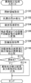
- FIG. 11 shows a flowchart showing an example of the flow of the foreign matter detection process executed on the console 12 of the present embodiment.
- the foreign matter detection process of the present embodiment includes the processes of steps S107 to S111 instead of steps S106 to S110 of the foreign matter detection process of the first embodiment (see FIG. 8).
- step S107 the detection unit 64 acquires a reference visible light image as described above.
- the second acquisition unit 62 acquires a visible light image from the visible light camera 31 as described above.
- the detection unit 64 compares the reference visible light image with the visible light image as described above. Based on the comparison result of this step, in the next step S112, the detection unit 64 determines whether or not there is a foreign substance in the detection area 74.
- the console 12 of the present embodiment it is possible to detect whether or not there is a foreign substance in the detection area 74 based on the visible light image taken by the visible light camera 31. Therefore, according to the console 12 of the present embodiment, even after the positioning is completed by the user or even if it is difficult for the user to see the irradiation area 70 of the radiation R, a foreign substance other than the object to be imaged in the irradiation area 70 of the radiation R. It is possible to appropriately detect the presence or absence of.
- the distance image taken by the TOF camera 39 and the distance image taken by the visible light camera 31 may be used to detect the presence or absence of foreign matter in the irradiation region 70.
- the detection unit 64 may issue a foreign matter handling instruction (see FIG. 8, step S114 of the foreign matter detection process).
- the irradiation region 70 may be photographed from different directions by the TOF camera 39 and the visible light camera 31, and the foreign matter may be detected from different directions.
- FIG. 12 shows a side view showing an example of the appearance of the mammography apparatus 10 of the present embodiment.
- the mammography apparatus 10 of the present embodiment is different from the mammography apparatus 10 of the second embodiment (see FIG. 10) in the position where the visible light camera 31 is provided.
- the visible light camera 31 of the present embodiment is provided on the subject W side of the irradiation unit 37.
- the imageable region 72 of the visible light camera 31 of the present embodiment includes the irradiation region 70 and includes the region provided with the compression plate 40. Further, the imageable region 72 of the visible light camera 31 of the present embodiment is defined as a region on the chest wall side of the breast WB of the subject W that can be imaged.
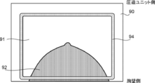
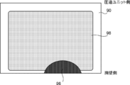
- FIG. 14 shows an example of a visible light image 90 taken by the visible light camera 31 of the present embodiment.
- the visible light image 90 taken by the visible light camera 31 includes an image corresponding to the compression plate 40.
- the bottom 43 of the compression plate 40 of the present embodiment is made of a transparent material, the breast WB is reflected in the bottom region 91 of the visible light image 90 corresponding to the bottom 43 of the compression plate 40. This results in a state in which the breast image 92 is included.
- the visible light image 90 shows the edge image 94 corresponding to the edge portion of the compression plate 40.
- the edge image 94 is an image showing the wall portion 44 of the bottom portion 43.
- the wall portion 44 of the compression plate 40 is more easily reflected in the visible light image 90 than the bottom portion 43. It is preferable that it is.
- the visible light image 90 is processed so that the bottom portion 43 and the wall portion 44 can be distinguished from each other.
- the edge portion of the compression plate 40 is emphasized as compared with the periphery.
- the material of the wall portion 44 may be a material that is easily reflected in the visible light image 90.
- the material of the wall portion 44 at least one of a material having a color different from that of the photographing table 30 and the breast WB, a phosphorescent material, and a fluorescent material may be used.
- the radiation source 37R side of the wall portion 44 of the compression plate 40 may be in a state where it can be easily reflected in the visible light image 90.
- at least one of a material having a color different from that of the photographing table 30 and the breast WB, a phosphorescent material, and a fluorescent material may be applied or attached to the surface of the wall portion 44 on the radiation source 37R side. good.
- various methods such as painting, sticking of members, coloring of the compression member on the material, and surface treatment can be adopted. Even if the bottom portion 43 and the wall portion 44 are made of materials having the same color, the apparent color may change depending on the thickness thereof.
- FIG. 15 shows a functional block diagram of an example of the functional configuration of the console 12 of the present embodiment.
- the console 12 of the present embodiment is different in that the console 12 of each of the above embodiments includes a third acquisition unit 66 instead of the first acquisition unit 60 (see FIG. 6).
- the third acquisition unit 66 has a function of acquiring compression member information indicating the type of the compression plate 40 attached to the compression unit 36.
- the size of the bottom 43 of the compression plate 40 of the present embodiment is determined according to the type of the compression plate 40. Therefore, the position and size of the edge image 94 included in the visible light image 90 are determined according to the type of the compression plate 40 attached to the compression unit 36.
- the support portion 46 of the compression plate 40 on the side attached to the compression unit 36 of the present embodiment is provided with a compression plate identifier (not shown) for identifying the type of the compression plate 40.
- the compression unit 36 is provided with an identifier sensor (not shown). The identifier sensor reads the compression plate identifier provided on the support portion 46 of the compression plate 40.
- the third acquisition unit 66 acquires the compression plate identifier read by the identifier sensor as the compression member information via the I / F unit 24 and the I / F unit 54.
- the compression member information acquired by the third acquisition unit 66 is output to the detection unit 64.
- the method by which the third acquisition unit 66 of the present embodiment acquires the compression member information is not limited to the above embodiment.
- the third acquisition unit 66 may acquire the type of photographing as the compression member information from the photographing menu or the like.
- the detection unit 64 of the present embodiment has a function of detecting the presence or absence of a foreign substance other than the imaging target in the irradiation region 70 based on the visible light image, as in the detection unit 64 of the second embodiment.
- the processing content required for is different.
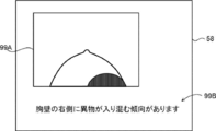
- the detection unit 64 of the present embodiment extracts the edge image 94 from the visible light image 90, and if the extracted edge image 94 is missing, determines that there is a foreign substance in the irradiation region 70. On the other hand, the detection unit 64 extracts the edge image 94 from the visible light image 90, and if the extracted edge image 94 is not missing, determines that there is no foreign matter in the irradiation region 70.
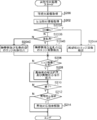
- FIG. 17 shows a flowchart showing an example of the flow of the foreign matter detection process executed on the console 12 of the present embodiment.
- step S200 the second acquisition unit 62 acquires the visible light image 90 from the visible light camera 31 as described above.
- the third acquisition unit 66 acquires the compression member information as described above.
- the detection unit 64 extracts the edge image 94 from the visible light image 90 acquired in the step S200 based on the compression member information acquired in the step S202.
- the specific method by which the detection unit 64 extracts the edge image 94 from the visible light image 90 is not particularly limited.
- the detection unit 64 may extract the edge image 94 by applying the existing image processing for edge detection.
- the detection unit 64 stores typical pattern data of the edge image 94 as a template in advance, and derives the similarity to the pattern data while searching the visible light image 90 with the template. Then, the detection unit 64 may extract the edge image 94 by applying template matching that considers that the edge image 94 exists at a place where the similarity is equal to or higher than the reference value and becomes the maximum.
- the detection unit 64 of the present embodiment estimates the shape and size of the edge image 94 according to the type of the compression plate 40 represented by the compression member information, and uses it for extracting the edge image 94. By estimating the shape and size of the edge image 94 according to the type of the compression plate 40 represented by the compression member information in this way, the edge image 94 can be extracted more accurately, and the processing for extraction is possible. The processing load on the above can be reduced.
- the detection unit 64 determines whether or not the edge image 94 extracted in the above step S204 has a chip.
- the detection unit 64 of the present embodiment determines whether or not there is a chip by comparing the reference edge image and the edge image 94.
- the visible light image 90 or the edge image 94 taken by the visible light camera 31 when there is no foreign matter in the irradiation region 70 is obtained in advance as the reference edge image.
- the device for storing the reference edge image is not limited, and may be stored in, for example, the storage unit 22 of the mammography device 10 or the storage unit 52 of the console 12.
- the detection unit 64 compares the edge image 94 extracted in step S204 with the reference edge image.
- the comparison is performed by deriving the difference between the pixel values of the extracted edge image 94 and the reference edge image. More specifically, there is a region in which a predetermined number or more of pixels in which the absolute value of the difference between the pixel value of the extracted edge image 94 and the pixel value of the reference edge image is larger than the chip detection threshold value are continuous. In this case, it is determined that the edge image 94 is chipped.
- the method by which the detection unit 64 determines whether or not the edge image 94 is chipped is not particularly limited. For example, when the outer peripheral line of the compression plate 40 recognized by the edge image 94 is interrupted by a predetermined number of pixels or more without using the reference edge image, the detection unit 64 has a chip in the edge image 94. It may be in the form of determining.
- step S206 If the edge image 94 is not chipped, the determination in step S206 becomes a negative determination, and the process proceeds to step S210. In this case, it corresponds to the case where there is no foreign matter in the irradiation area 70. On the other hand, if the edge image 94 is chipped, the determination in step S206 becomes an affirmative determination, and the process proceeds to step S208. In this case, it corresponds to the case where there is a foreign substance in the irradiation area 70.
- step S208 the detection unit 64 gives a detection result indicating the presence of foreign matter and an instruction for dealing with the foreign matter, as in S114 of the foreign matter detection processing (see FIGS. 8 and 11) of the first and second embodiments. After the output, the process proceeds to step S210.
- step S210 the detection unit 64 determines whether or not to end the foreign matter detection process being executed.
- the detection unit 64 of the present embodiment determines that the foreign matter detection process is terminated when the termination condition is satisfied. For example, as an end condition, there is a case where the user gives an irradiation instruction of radiation R by the operation unit 56 or the like. Further, for example, as an end condition, there is a case where the user instructs the end of the foreign matter detection process by the operation unit 56 or the like. If the end condition is not satisfied, the determination in step S210 becomes a negative determination, the process returns to step S200, and the above processes S200 to S208 are repeated.
- the user who recognizes that the foreign matter is present in the irradiation area 70 is in a state where the foreign matter has not invaded into the irradiation area 70 by maintaining the posture of the subject W or the like. Therefore, the above process is repeated to continue determining whether or not there is a foreign substance in the irradiation region 70.
- step S212 the detection unit 64 determines whether or not a foreign matter handling instruction is being given. Specifically, it is determined whether or not the process of step S208 has been performed. If the process of step S208 is not performed, in other words, if there is no foreign matter in the irradiation area 70, the determination of step S212 becomes a negative determination, and the foreign matter detection process shown in FIG. 17 ends. On the other hand, when the process of step S208 is performed, in other words, when there is a foreign substance in the irradiation area 70, the determination in step S212 becomes an affirmative determination, and the process proceeds to step S214.
- step S214 the detection unit 64 cancels the foreign matter handling instruction given in step S208. For example, when the detection unit 64 outputs information for warning the user that there is a foreign matter in the detection area 74 as an instruction for dealing with foreign matter, the warning is canceled by stopping the output of the information for warning. do.
- the process of step S214 is completed, the foreign matter detection process shown in FIG. 17 is completed.
- the foreign matter in the irradiation region 70 is based on the chipping of the image of the compression plate 40 included in the visible light image 90 taken by the visible light camera 31, particularly the chipping of the edge image 94. Detect the presence or absence. Therefore, according to the console 12 of the present embodiment, even after the positioning is completed by the user or even if it is difficult for the user to see the irradiation area 70 of the radiation R, a foreign substance other than the object to be imaged in the irradiation area 70 of the radiation R. It is possible to appropriately detect the presence or absence of.
- the detection unit 64 of this modification detects whether or not there is a chip in the region of the edge image 94 corresponding to the side of the subject W on the chest wall side.
- the mammography apparatus 10 can perform at least two types of photographing as the type of photographing a radiographic image. Specifically, the mammography apparatus 10 performs CC (Cranio-Caudal) imaging in which the imaging direction is the cranio-caudal direction with respect to the breast WB, and MLO (Medio-Lateral Oblique) in which the imaging direction is the medial-lateral oblique direction. At least two types of photography can be performed.
- CC Cirranio-Caudal
- MLO Medio-Lateral Oblique
- FIG. 18 shows an example of the states of the imaging table 30, the arm portion 32, and the radiation source 37R in CC imaging and MLO imaging.
- the imaging surface 30A is adjusted to face the upper side of the mammography apparatus 10 (the head WH side of the subject W) while facing the radiation source 37R. ..
- the radiation source 37R irradiates the breast WB with the radiation R from the head WH side to the foot side of the subject W, and CC imaging is performed.
- the detection unit 64 of this modification detects whether or not there is a defect in the region of the edge image 94 corresponding to the side of the subject W on the chest wall side when performing CC imaging.
- the arm portion 32 in the case of performing MLO imaging, is predetermined in the ⁇ direction or the + direction, for example, within a range of 45 degrees or more and less than 90 degrees, as compared with the case of performing CC imaging.
- the arm portion 32 is tilted with respect to the head-to-tail direction of the subject W by rotating it to a vertical angle. Specifically, when photographing the left breast, the arm portion 32 is tilted in the + direction with the imaging surface 30A and the radiation source 37R facing each other, and the imaging surface 30A is tilted to the right. ..
- the left side of the compression plate 40 is maintained in a state of being up and the right side is maintained in a state of being down.
- the left and right sides in this modification correspond to the left and right sides of the subject W facing the photographing table 30.
- foreign matter tends to easily enter from the upper side of the tilted photographing table 30. Therefore, foreign matter tends to easily enter from the upper side of the compression plate 40.
- the detection unit 64 of this modification detects whether or not there is a defect in the region of the edge image 94 corresponding to each of the chest wall side and the left side of the subject W when performing MLO imaging of the left breast WB. do.
- the arm portion 32 When photographing the right breast, the arm portion 32 is tilted in the minus direction with the imaging surface 30A and the radiation source 37R facing each other, and the imaging surface 30A is tilted to the left.
- the radiation R is irradiated from the radiation source 37R to the breast WB from the center side of the body of the subject W toward the outside (from between the breast WBs of the subject W toward the arm side), and MLO imaging is performed. Is done.
- the detection unit 64 of this modification detects whether or not there is a defect in the region of the edge image 94 corresponding to each side of the chest wall side and the right side of the subject W when performing MLO imaging of the right breast WB. do.
- FIG. 19 shows a flowchart showing an example of the flow of the foreign matter detection process executed on the console 12 of this modified example.
- the foreign matter detection process of the present modification shown in FIG. 19 includes the processes of steps S203A and S203B after step S202 of the foreign matter detection process (see FIG. 17) of the above-described embodiment, and the processes of steps S204A to S204C instead of step S204. The difference is that it has.
- the detection unit 64 determines whether or not the type of shooting is CC shooting.
- the method by which the detection unit 64 determines whether or not the type of imaging is CC imaging is not particularly limited.
- the type of shooting may be specified by referring to the shooting menu.
- step S203A When the type of shooting is CC shooting, the judgment in step S203A becomes an affirmative judgment, and the process proceeds to step S204A.
- step S204A as described above, the detection unit 64 detects whether or not there is a chip in the region of the edge image 94 corresponding to the side of the subject W on the chest wall side, and then proceeds to step S206.
- step S203A determines whether or not the image of the left breast WB is taken. In the case of photographing the left breast WB, the determination in step S203B becomes an affirmative determination, and the process proceeds to step S204B.
- step S204B the detection unit 64 detects whether or not there is a defect in the region of the edge image 94 corresponding to each side of the chest wall side and the left side of the subject W, and then proceeds to step S206.
- step S204C the detection unit 64 detects whether or not there is a defect in the region of the edge image 94 corresponding to each of the chest wall side and the right side of the subject W, and then proceeds to step S206.
- the entire edge image 94 is not used for detecting the presence or absence of foreign matter in the irradiation region 70, the foreign matter detection process can be performed faster and the processing load can be reduced. ..
- the compression plate 40 When a phosphorescent material is used for the edge portion of the compression plate 40, the compression plate 40 does not compress the subject W, does not irradiate the radiation R, and the compression plate 40 has a compression thickness. It is preferable to irradiate the edge portion with light for a certain period of time at a predetermined time interval to store the light in a state where the light is not applied. Further, when irradiating the phosphorescent material at the edge portion with light for phosphorescence, it is preferable that the compression plate 40 is located at a position away from the radiation source 37R. In other words, it is preferable to lower the height of the compression plate 40.
- the edge portion of the compression plate 40 corresponds to the wall portion 44 and has a height different from that of the bottom portion 43. Therefore, the edge portion is also taken from the distance image taken by the TOF camera 39 of the first embodiment. Image can be detected. Therefore, a distance image taken by the TOF camera 39 may be applied to the present embodiment instead of the visible light image 90.
- FIG. 20 shows a side view showing an example of the appearance of the mammography apparatus 10 of the present embodiment.
- the visible light camera 31 is provided at the same position as the mammography apparatus 10 of the third embodiment (see FIG. 12).
- the projector 29 is provided at a position of the arm portion 32 below the irradiation unit 37 and away from the subject W.
- the projector 29 of the present embodiment has a function of projecting the projected image 98 on the irradiation surface of the compression plate 40 to which the radiation R is irradiated.
- the projector 29 of the present embodiment has a function of projecting a projected image 98 on a surface (hereinafter, referred to as a projection surface 43A) on the bottom 43 of the compression plate 40 on which radiation R is irradiated.
- the projector 29 of the present embodiment is an example of the image projection device of the present disclosure.
- the projection surface 43A of the compression plate 40 is in a state where the projected image 98 can be easily displayed.
- the projection surface 43A may be formed by roughening the surface of the bottom 43 of the compression plate 40 on the radiation source 37R side.
- the projection surface 43A may be formed by attaching a specular reflection sheet to the surface of the compression plate 40.
- FIG. 22 shows an example of the visible light image 90 taken by the visible light camera 31 of the present embodiment.
- the visible light image 90 captured by the visible light camera 31 includes a projected image 98.
- the visible light image 90 includes an image of the projected image 98 displayed on the projection surface 43A, but for convenience of explanation, the projected image 98 is also included in the image due to the projected image 98 being reflected. That is.
- the projected image 98 included in the visible light image 90 of the present embodiment is an example of an image of a region corresponding to the irradiation field of the radiation of the present disclosure.
- FIG. 14 shows a functional block diagram of an example of the functional configuration of the console 12 of the present embodiment. As shown in FIG. 23, the console 12 of the present embodiment is different from the console 12 of each of the above embodiments (see FIG. 6 and the like) in that the projection control unit 68 is further provided.
- the projection control unit 68 has a function of controlling the projection image 98 to be projected onto the projector 29 in the area including the irradiation field 71 of the radiation R.
- the projected image 98 projected by the projector 29 and projected on the projection surface 43A of the compression plate 40 is the same as the range of the irradiation field 71 of the radiation R on the projection surface 43A of the compression plate 40.
- the position and size are used. Specifically, as shown in FIG. 21, the position and size of the projected image 98 are the same as the cross section of the irradiation region 70 on the projection surface 43A when the irradiation region 70 is blocked by the bottom 43.
- the projection control unit 68 has the same position and size of the projected image 98 on the projection surface 43A as the range of the irradiation field 71 of the radiation R on the projection surface 43A (hereinafter, simply referred to as “the range of the irradiation field 71”). And control for size. As described above, the size and shape of the irradiation field 71 are determined according to the size of the imaging surface (not shown) of the radiation detector 28, the size of the breast WB to be imaged, and the like. Therefore, as shown in FIG.
- the size and position of the range of the irradiation field 71 is the position of the radiation source 37R, that is, the distance between the radiation source 37R, which is a so-called SID (Source Image Distance), and the imaging surface of the radiation detector 28. It is determined according to h_s, the height h_c of the compression plate 40 corresponding to the thickness of the breast WB, and the distance h_d between the imaging surface 30A of the imaging table 30 and the imaging surface of the radiation detector 28.
- the thickness of the bottom 43 of the compression plate 40 is ignored, but more accurately, the value obtained by adding the thickness of the bottom 43 to the height h_c of the compression plate 40 is used. Further, when the projection surface 43A of the bottom portion 43 is provided with a specular reflection sheet or the like for displaying the projected image 98 as described above, a value obtained by further adding the thickness of the compression plate 40 mirror reflection sheet or the like is used.
- the projection control unit 68 of the present embodiment derives the position and size of the projected image 98 on the projection surface 43A by using the above equation (1).
- the coordinates, SID, and the like of the radiation source 37R required for using the above equation (1) are included in the information representing the irradiation area 70 acquired by the first acquisition unit.
- the projection control unit 68 controls the projector 29 to project the projected image 98 at the position and size of the projected image 98 on the derived projection surface 43A. Specifically, the projection control unit 68 outputs projected image projection information representing the position and size of the projected image 98 to the projector 29 via the I / F unit 54.
- the projector 29 projects the projected image 98 based on the projected image projection information input from the console 12.
- the method by which the projector 29 projects the projected image 98 based on the projected image projection information is not particularly limited. For example, a projected image 98 corresponding to the size and position of the imaging surface of the radiation detector 28 or the imaging surface 30A of the imaging table 30 is prepared in advance, and the prepared projected image 98 is based on the projected image projection information.
- the projected image data may be in the form of generating the projected image data for projecting the desired projected image 98 by trimming. Further, for example, the projected image data of a plurality of projected images 98 corresponding to each of the plurality of assumed positions and sizes are prepared in advance, and the projected image data of the projected image 98 according to the projected image projection information is prepared from the prepared images. May be used as a form for selecting.
- the image of the projected image 98 is not particularly limited, but it is preferable to use a single color, particularly a single color image different from the photographing surface 30A of the photographing table 30.
- the projected image 98 has the same position and size as the range of the irradiation field 71, but the position and size of the projected image 98 includes the range of the irradiation field 71.
- the size of the projected image 98 is larger than the range of the irradiation field 71, it is preferable to use the projected image 98 including an image representing the range of the irradiation field 71.
- the detection unit 64 of the present embodiment has a function of detecting the presence or absence of a foreign substance other than the imaging target in the irradiation region 70 based on the visible light image 90 acquired by the second acquisition unit, but the processing content required for the detection. Is different.
- FIG. 25 shows an example of the visible light image 90 taken by the visible light camera 31 with the projected image 98 projected on the projection surface 43A and the foreign matter invading the irradiation area 70. As shown in FIG. 25, the foreign matter image 96 is shown on the projected image 98 included in the visible light image 90.
- the detection unit 64 of the present embodiment detects whether or not the foreign matter image 96 is present on the projected image 98 included in the visible light image 90, and if the foreign matter image 96 is present on the projected image 98, it is irradiated. It is determined that there is a foreign substance in the area 70. On the other hand, when the foreign matter image 96 does not exist on the projected image 98 included in the visible light image 90, the detection unit 64 determines that there is no foreign matter in the irradiation region 70. Since the visible light image 90 captured by the visible light camera 31 is actually distorted by the lens of the visible light camera 31, the detection unit 64 considers the distortion caused by the lens and considers the distortion of the foreign matter in the irradiation region 70. It is preferable to detect the presence or absence.
- the detection unit 64 has the same range of the projected image 98 and the irradiation field 71 on the projection surface 43A, and the foreign matter image 96 is placed on the projected image 98 included in the visible light image 90. By detecting the presence or absence, it is possible to more accurately detect whether or not a foreign substance is present in the irradiation region 70.
- FIG. 26 shows a flowchart showing an example of the flow of the foreign matter detection process executed on the console 12 of the present embodiment.
- the foreign matter detection process of the present embodiment shown in FIG. 26 is different from the foreign matter detection process of the third embodiment (see FIG. 17) in that the process of steps S194 to S196 is provided before step S200.
- the projection control unit 68 first determines in step S194 whether or not to start the projection of the projected image 98.
- the projection of the visible light image 90 is started from the projector 29 when the predetermined projection start condition is satisfied.
- the projection start condition is not particularly limited, but for example, the presence or absence of a foreign substance in the irradiation region 70 is preferably detected after the positioning of the subject W is completed. Therefore, the projection start condition may be the case where the positioning of the subject W is completed. Can be mentioned. In this case, the form for determining that the positioning of the subject W is completed is not particularly limited.
- a predetermined time elapses after the movement of the compression plate 40 in the direction of pressing the breast WB is stopped or the movement speed becomes equal to or less than the threshold speed, or the height of the compression plate 40 does not change.
- a predetermined time has passed since then.
- a projection start condition for example, a case where the user instructs the start of projection by the operation unit 56 or the like can be mentioned.
- step S194 is a negative determination until the projection start condition is satisfied. On the other hand, when the projection start condition is satisfied, the determination in step S194 becomes an affirmative determination, and the process proceeds to step S196.
- step S196 the projection control unit 68 derives the position and size of the range of the irradiation field 71 on the projection surface 43A as described above.
- the projection control unit 68 of the present embodiment derives the coordinates of the projected image 98 on the projection surface 43A corresponding to the position and size of the range of the irradiation field 71 by using the above equation (1).
- the projection control unit 68 controls the projector 29 to project the projected image 98 according to the position and size of the range of the irradiation field 71 derived in the step S196, as described above.
- the projector 29 may project an image according to another purpose. For example, in order to support the positioning of the subject W, an image or the like representing the skin line of the breast WB when the ideal positioning is performed may be projected from the projector 29 on the projection surface 43A of the compression plate 40. In this way, when the projector 29 projects another image onto the projection surface 43A, the projection control unit 68 controls to end the projection of the other image and switch to the projection of the projected image 98.
- the mammography device 10 is provided with an irradiation field projection device (see FIG. 27) for displaying the range of the irradiation field 71 with visible light, and visible light is emitted from the irradiation field projection device toward the projection surface 43A. If so, the projection control unit 68 controls the irradiation field projection device to stop the irradiation of visible light.
- step S198 the visible light image 90 acquired by the second acquisition unit 62 in the next step S200 is in the state shown in FIG. 22 or the state shown in FIG. 25.
- the foreign matter detection process of the present embodiment is different in that it includes the foreign matter detection process (see FIG. 17) in the third embodiment and the process of step S207 instead of steps S204 and S206.
- step S207 the detection unit 64 determines whether or not there is a foreign substance in the irradiation area 70.
- the detection unit 64 of the present embodiment has a foreign matter in the irradiation region 70 depending on whether or not the foreign matter image 96 is present on the projection image 98 included in the visible light image 90 acquired in step S200. Judge whether or not.
- the specific method by which the detection unit 64 determines whether or not the foreign matter image 96 is present on the projected image 98 included in the visible light image 90 is not particularly limited. For example, a visible light image 90 (see FIG.
- the device for storing the reference projection image is not limited, and for example, it may be stored in the storage unit 22 of the mammography device 10 or may be stored in the storage unit 52 of the console 12.
- the detection unit 64 makes a comparison by deriving the difference between the pixel values of the projected image 98 included in the visible light image 90 and the projected image included in the reference projected image.
- a pixel in which the absolute value of the difference between the pixel value of the projected image 98 included in the visible light image 90 and the pixel value of the projected image included in the reference projected image is larger than the foreign matter detection threshold is predetermined. When there are more than a certain number of continuous regions, it is determined that there is a foreign substance in the irradiation region 70.
- the foreign matter detection process of the present embodiment is different in that the foreign matter detection process (see FIG. 17) in the third embodiment and the process of step S216 are provided after step S214.
- the projection control unit 68 controls the projector 29 to end the projection of the projected image 98. In response to this control, the projector 29 ends the projection of the projected image 98.
- the foreign matter detection process shown in FIG. 26 is completed.
- the projected image 98 is projected from the projector 29 onto the projection surface 43A of the compression plate 40, and the projected image 98 projected on the projection surface 43A by the visible light camera 31 is captured.
- the optical image 90 is acquired.
- the console 12 detects the presence or absence of foreign matter in the irradiation region 70 depending on whether or not the foreign matter image 96 is present on the projected image 98 included in the acquired visible light image 90. Therefore, according to the console 12 of the present embodiment, even after the positioning is completed by the user or even if it is difficult for the user to see the irradiation area 70 of the radiation R, a foreign substance other than the object to be imaged in the irradiation area 70 of the radiation R. It is possible to appropriately detect the presence or absence of.
- the mammography apparatus 10 of the present embodiment includes a visible light source 37V, and suggests an irradiation field 71 by projecting visible light V emitted from the visible light source 37V and reflected by the mirror 27. ..
- the visible light image 90 is acquired.
- the visible light image 90 can be acquired more clearly.
- the visible light image 90 obtained by capturing the projected image 98 projected from the projector 29 has been described, but the mammography device 10 includes an irradiation field projection device that indicates the range of the irradiation field 71 with visible light. If this is the case, a visible light image 90 obtained by capturing visible light indicating the range of the irradiation field 71 may be used instead of the projected image 98. Specifically, a visible light image 90 obtained by photographing a state in which visible light is irradiated on the projection surface 43A by an irradiation field projection device may be used.
- FIG. 27 shows a side view showing an example of the appearance of the mammography apparatus 10 in this case.
- the mammography apparatus 10 of the present embodiment includes a collimator 21, a mirror 27, and a visible light source 37V in place of the projector 29 of the mammography apparatus 10 (see FIG. 20) of the above embodiment.
- the collimator 21, the mirror 27, and the visible light source 37V of the present embodiment are examples of the irradiation field projection device of the present disclosure.
- the visible light source 37V lights up when a voltage is applied to generate visible light, and emits the generated visible light.
- the visible light source 37V is provided outside the irradiation region 70 of the radiation R.
- the mirror 27 reflects the visible light V emitted from the visible light source 37V toward the photographing surface 30A of the photographing table 30, thereby suggesting the irradiation field 71 of the radiation R by the visible light.
- the mirror 27 allows the radiation R emitted from the radiation source 37R to pass through.
- the collimator 21 has a function of limiting the radiation R and the irradiation field 71 of visible light. As shown in FIG. 27, the collimator 21 is provided between the mirror 27 and the photographing table 30. The irradiation field 71 is limited according to the opening of the collimator 21.
- the projection control unit 68 of the console 12 controls to project the projected image 98 from the projector 29, but instead of controlling the projection image 98 from the projector 29, it corresponds to the range from the visible light source 37V to the irradiation field 71. It suffices to control the irradiation of visible light.
- the visible light image 90 taken by the visible light camera 31 in a state where the projection surface 43A is irradiated with visible light from the visible light source 37V is projected instead of the projection image 98 included in the above-mentioned visible light image 90.
- An image corresponding to a region irradiated with visible light on the surface 43A (hereinafter, referred to as a “light irradiation field image”) is included. Therefore, instead of detecting whether or not the foreign matter image 96 is present on the projected image 98 included in the visible light image 90, the detection unit 64 detects the foreign matter on the light irradiation field image included in the visible light image 90. By detecting the presence or absence of the image 96, the presence or absence of foreign matter in the irradiation region 70 can be detected.
- the console 12 of each of the above forms includes a CPU 50A as at least one processor and a ROM 50B for storing instructions that can be executed by the CPU 50A.
- the CPU 50A is a TOF camera 39 or a TOF camera 39 having a region including an irradiation region 70, which is a space where radiation R is irradiated from the radiation source 37R to the breast WB of the subject imaged by the mammography apparatus 10, as a radiographic region (72).
- a distance image or a visible light image captured by the visible light camera 31 is acquired, and the presence or absence of a foreign substance other than the imaging target in the irradiation region 70 is detected based on the distance image or the visible light image.
- console 12 of each of the above forms it is possible to appropriately detect the presence or absence of a foreign substance other than the imaged object in the irradiation region 70 of the radiation R, so that the foreign substance is reflected in the radiation image captured by the mammography apparatus 10. It can suppress the crowding. As a result, re-shooting due to so-called photo loss can be suppressed.
- the detection unit 64 of the console 12 further detects whether or not the foreign matter is reflected in the photographed radiation image.
- the detection unit 64 may detect the foreign matter image included in the radiation image based on the position of the foreign matter image 96 detected from the distance image or the visible light image 90.
- the detection unit 64 may detect whether or not a foreign matter image is included in the radiographic image by using CAD (Computer-Aided Diagnosis). Further, when the radiographic image contains a foreign matter image, it is preferable to perform processing such as warning the user to that effect.
- the visible light image 90 or the distance image including the foreign matter image is associated with the position of the foreign matter image, the type of shooting, the information representing the user, the information representing the subject W, and the like, and accumulated as the foreign matter detection result information. You may leave it.
- the accumulated foreign matter detection result information By analyzing the accumulated foreign matter detection result information and performing statistical processing, for example, conditions for foreign matter to easily enter the irradiation region 70 are extracted for each user, each type of photographing, and each condition related to the subject W. be able to.
- FIG. 28 shows an example of the information displayed on the display unit 58 for supporting the positioning.
- a schematic diagram 99A and advice information 99B corresponding to typical foreign substances according to the extraction result are displayed on the display unit 58 as information for supporting positioning.
- Schematic diagram 99A is a diagram in which a foreign body image is superimposed on a breast schema diagram, a breast WB skin line image extracted from a radiographic image, a general breast diagram, or the like.
- the advice information 99B is information for presenting to the user a position or the like where a foreign substance tends to exist based on the extraction result.
- the user performs the positioning, it is possible to further suppress the invasion of foreign matter into the irradiation area 70 by displaying the information for supporting the positioning as shown in FIG. 28 on the display unit 58 or the like.
- the presence or absence of foreign matter in the irradiation region 70 is detected from the captured image captured by one imaging device, but the plurality of imaging devices are used and the imaging is performed by each of the plurality of imaging devices. It may be in the form of using the photographed image.
- TOF camera 39 1 may be in the form of using the two imaging devices 39 2.
- the one alone TOF camera 39 1 of the imaging region 72 1 and the TOF camera 39 2 of the imaging region 72 2 is useful if you do not fully encompass the irradiated region 70.
- the distance image captured by TOF camera 39 1, and a distance image captured by TOF camera 39 2, combined together position is used as a range images
- the presence or absence of foreign matter in the irradiation region 70 can be detected in the same manner as in the first embodiment.
- the TOF camera 39 is provided on the compression unit 36 side in the irradiation unit 37 of the mammography device 10
- a mode in which the visible light camera 31 is provided in the vicinity of the collimator 33 will be described.
- the positions where the TOF camera 39 and the visible light camera 31 are provided are not limited to this embodiment.
- Each of the TOF camera 39 and the visible light camera 31 may be arranged in a state in which the irradiation area 70 is included in the imageable area (photographable area 72) as described above, and the positions thereof are not limited.
- the TOF camera 39 may be provided on the face guard 38 side of the radiation irradiation unit 37.
- the TOF camera 39 or the visible light camera 31 may be provided outside the mammography apparatus 10. Further, for example, when both the TOF camera 39 and the visible light camera 31 are provided, the TOF camera 39 and the visible light camera 31 may be provided side by side at the same position or may be provided at different positions.
- a mode of capturing a distance image by a TOF method using a TOF camera has been described, but a distance image capturing device for capturing a distance image is a TOF camera.
- a distance image capturing device for capturing a distance image is a TOF camera.
- a form in which a distance image capturing device that irradiates a patterned infrared light to an imaging target and captures a distance image according to the reflected light from the imaging target is used, and a distance image is captured by applying the Structured Light method. May be.
- a DFD (Depth from Defocus) method for restoring the distance based on the degree of blurring of the edge region reflected in the distance image may be applied.
- a form using a distance image taken by a monocular camera using a color aperture filter is known.
- the form in which the mammography apparatus 10 is applied is described as an example of the radiation imaging apparatus of the present disclosure.
- the radiation imaging apparatus in the first and second embodiments is a mammography apparatus. Not limited to.
- it may be in the form of applying a radiographic imaging apparatus for performing general imaging.
- console 12 is an example of the information processing device of the present disclosure
- devices other than the console 12 may have the functions of the information processing device of the present disclosure.
- a part or all of the functions of the first acquisition unit 60, the second acquisition unit 62, and the detection unit 64 may be provided by, for example, a mammography device 10 or an external device other than the console 12.
- the hardware structure of the processing unit that executes various processes such as the first acquisition unit 60, the second acquisition unit 62, and the detection unit 64 is as follows.
- the various processors shown can be used.
- the various processors include a CPU, which is a general-purpose processor that executes software (program) and functions as various processing units, and a circuit after manufacturing an FPGA (Field Programmable Gate Array) or the like.
- Dedicated electricity which is a processor with a circuit configuration specially designed to execute specific processing such as programmable logic device (PLD), ASIC (Application Specific Integrated Circuit), which is a processor whose configuration can be changed. Circuits and the like are included.
- One processing unit may be composed of one of these various processors, or a combination of two or more processors of the same type or different types (for example, a combination of a plurality of FPGAs or a combination of a CPU and an FPGA). It may be composed of a combination). Further, a plurality of processing units may be configured by one processor.
- one processor is configured by a combination of one or more CPUs and software, as represented by a computer such as a client and a server.
- a processor functions as a plurality of processing units.
- SoC System On Chip
- the various processing units are configured by using one or more of the above-mentioned various processors as a hardware structure.
- an electric circuit in which circuit elements such as semiconductor elements are combined can be used.
- the foreign matter detection processing program 51 is provided in a form recorded on a recording medium such as a CD-ROM (Compact Disc Read Only Memory), a DVD-ROM (Digital Versatile Disc Read Only Memory), and a USB (Universal Serial Bus) memory. You may. Further, the foreign matter detection processing program 51 may be downloaded from an external device via a network.
- a recording medium such as a CD-ROM (Compact Disc Read Only Memory), a DVD-ROM (Digital Versatile Disc Read Only Memory), and a USB (Universal Serial Bus) memory. You may. Further, the foreign matter detection processing program 51 may be downloaded from an external device via a network.
Landscapes
- Engineering & Computer Science (AREA)
- Health & Medical Sciences (AREA)
- Life Sciences & Earth Sciences (AREA)
- Medical Informatics (AREA)
- Physics & Mathematics (AREA)
- General Health & Medical Sciences (AREA)
- Nuclear Medicine, Radiotherapy & Molecular Imaging (AREA)
- Radiology & Medical Imaging (AREA)
- Molecular Biology (AREA)
- Heart & Thoracic Surgery (AREA)
- Veterinary Medicine (AREA)
- Public Health (AREA)
- Biophysics (AREA)
- High Energy & Nuclear Physics (AREA)
- Optics & Photonics (AREA)
- Pathology (AREA)
- Biomedical Technology (AREA)
- Animal Behavior & Ethology (AREA)
- Surgery (AREA)
- General Physics & Mathematics (AREA)
- Theoretical Computer Science (AREA)
- Computer Vision & Pattern Recognition (AREA)
- Quality & Reliability (AREA)
- Multimedia (AREA)
- Dentistry (AREA)
- Oral & Maxillofacial Surgery (AREA)
- Apparatus For Radiation Diagnosis (AREA)
Priority Applications (3)
| Application Number | Priority Date | Filing Date | Title |
|---|---|---|---|
| EP21779051.8A EP4129183B1 (en) | 2020-03-31 | 2021-03-19 | Information processing device, radiographic imaging device, information processing method, and information processing program |
| JP2022511929A JP7430779B2 (ja) | 2020-03-31 | 2021-03-19 | 情報処理装置、放射線画像撮影装置、情報処理方法、及び情報処理プログラム |
| US17/930,720 US12387332B2 (en) | 2020-03-31 | 2022-09-09 | Information processing device, radiography apparatus, information processing method, and information processing program |
Applications Claiming Priority (4)
| Application Number | Priority Date | Filing Date | Title |
|---|---|---|---|
| JP2020-065268 | 2020-03-31 | ||
| JP2020065268 | 2020-03-31 | ||
| JP2020219603 | 2020-12-28 | ||
| JP2020-219603 | 2020-12-28 |
Related Child Applications (1)
| Application Number | Title | Priority Date | Filing Date |
|---|---|---|---|
| US17/930,720 Continuation US12387332B2 (en) | 2020-03-31 | 2022-09-09 | Information processing device, radiography apparatus, information processing method, and information processing program |
Publications (1)
| Publication Number | Publication Date |
|---|---|
| WO2021200289A1 true WO2021200289A1 (ja) | 2021-10-07 |
Family
ID=77928277
Family Applications (1)
| Application Number | Title | Priority Date | Filing Date |
|---|---|---|---|
| PCT/JP2021/011505 Ceased WO2021200289A1 (ja) | 2020-03-31 | 2021-03-19 | 情報処理装置、放射線画像撮影装置、情報処理方法、及び情報処理プログラム |
Country Status (4)
| Country | Link |
|---|---|
| US (1) | US12387332B2 (https=) |
| EP (1) | EP4129183B1 (https=) |
| JP (1) | JP7430779B2 (https=) |
| WO (1) | WO2021200289A1 (https=) |
Cited By (2)
| Publication number | Priority date | Publication date | Assignee | Title |
|---|---|---|---|---|
| JP7266334B1 (ja) | 2022-03-07 | 2023-04-28 | 株式会社アールエフ | X線撮影装置 |
| EP4671863A3 (en) * | 2021-11-22 | 2026-02-25 | J. Morita Manufacturing Corporation | Radiography image reading apparatus |
Families Citing this family (5)
| Publication number | Priority date | Publication date | Assignee | Title |
|---|---|---|---|---|
| JP7413223B2 (ja) * | 2020-09-30 | 2024-01-15 | 富士フイルム株式会社 | 制御装置、制御方法、及び制御プログラム |
| JP7321133B2 (ja) * | 2020-09-30 | 2023-08-04 | 富士フイルム株式会社 | 情報処理装置、情報処理方法及び情報処理プログラム |
| JP2024033602A (ja) * | 2022-08-30 | 2024-03-13 | 富士フイルム株式会社 | 乳房撮影装置 |
| US12251257B2 (en) * | 2022-10-19 | 2025-03-18 | GE Precision Healthcare LLC | System and method for analyzing breast support environment |
| DE102024207429A1 (de) * | 2024-08-06 | 2026-02-12 | Siemens Healthineers Ag | Mammographiesystem zum Bestimmen einer dreidimensionalen Form einer Brust |
Citations (7)
| Publication number | Priority date | Publication date | Assignee | Title |
|---|---|---|---|---|
| JP2009297273A (ja) * | 2008-06-13 | 2009-12-24 | Fujifilm Corp | 放射線画像撮影装置 |
| JP2011104149A (ja) * | 2009-11-18 | 2011-06-02 | Toshiba Corp | マンモグラフィ装置 |
| JP2017164312A (ja) * | 2016-03-16 | 2017-09-21 | キヤノン株式会社 | 放射線撮影装置、挿入状態判定方法、及びプログラム |
| JP2018157941A (ja) | 2017-03-22 | 2018-10-11 | 富士フイルム株式会社 | マンモグラフィ装置 |
| US20190021677A1 (en) * | 2017-07-18 | 2019-01-24 | Siemens Healthcare Gmbh | Methods and systems for classification and assessment using machine learning |
| JP2019536546A (ja) * | 2016-11-22 | 2019-12-19 | ゼネラル・エレクトリック・カンパニイ | 患者走査設定のための方法およびシステム |
| JP2020065268A (ja) | 2013-07-15 | 2020-04-23 | ジーイー ビデオ コンプレッション エルエルシー | 拡張機構を使用している層idの信号 |
Family Cites Families (12)
| Publication number | Priority date | Publication date | Assignee | Title |
|---|---|---|---|---|
| FI106293B (fi) * | 1998-11-27 | 2001-01-15 | Planmed Oy | Menetelmä ja laitteet kudosten kuvantamisessa |
| US10925564B2 (en) * | 2012-04-20 | 2021-02-23 | Siemens Medical Solutions Usa, Inc. | Medical imaging system with range imaging-based control |
| DE102012209190A1 (de) * | 2012-05-31 | 2013-12-05 | Siemens Aktiengesellschaft | Verfahren zu einer Erfassung von Informationen wenigstens eines auf einer Patientenlagerungsvorrichtung angeordneten Objekts in einer medizinischen Bildgebungsvorrichtung sowie eine medizinische Bildgebungsvorrichtung zur Durchführung des Verfahrens |
| JP6151029B2 (ja) | 2013-01-21 | 2017-06-21 | 東芝メディカルシステムズ株式会社 | 被曝警告装置およびx線診断装置 |
| CN106061392B (zh) | 2014-03-04 | 2020-03-31 | 皇家飞利浦有限公司 | 能够防止对目标造成非故意x射线辐射的医学成像系统 |
| US20180303440A1 (en) * | 2017-04-19 | 2018-10-25 | Digit Medical Corporation | Automatically controlled x-ray irradiation field limiting device |
| JP2019000460A (ja) * | 2017-06-16 | 2019-01-10 | キヤノン株式会社 | 放射線撮影装置、放射線撮影システム、放射線撮影方法、及びプログラム |
| EP3351180B1 (de) | 2017-08-10 | 2019-09-25 | Siemens Healthcare GmbH | Überwachungsverfahren und überwachungssystem |
| DE102018200108A1 (de) * | 2018-01-05 | 2019-07-11 | Siemens Healthcare Gmbh | Positionierung eines Untersuchungsobjekts bezüglich eines Röntgengeräts |
| US11026651B2 (en) * | 2018-01-19 | 2021-06-08 | Konica Minolta, Inc. | Radiographing control apparatus, radiographic imaging apparatus and radiographic imaging system |
| DE102018211106A1 (de) * | 2018-07-05 | 2020-01-09 | Siemens Healthcare Gmbh | Verfahren zur Reduktion eines Artefakts in einem Computertomographie-Bilddatensatz |
| US11375968B2 (en) * | 2020-04-06 | 2022-07-05 | GE Precision Healthcare LLC | Methods and systems for user and/or patient experience improvement in mammography |
-
2021
- 2021-03-19 WO PCT/JP2021/011505 patent/WO2021200289A1/ja not_active Ceased
- 2021-03-19 EP EP21779051.8A patent/EP4129183B1/en active Active
- 2021-03-19 JP JP2022511929A patent/JP7430779B2/ja active Active
-
2022
- 2022-09-09 US US17/930,720 patent/US12387332B2/en active Active
Patent Citations (7)
| Publication number | Priority date | Publication date | Assignee | Title |
|---|---|---|---|---|
| JP2009297273A (ja) * | 2008-06-13 | 2009-12-24 | Fujifilm Corp | 放射線画像撮影装置 |
| JP2011104149A (ja) * | 2009-11-18 | 2011-06-02 | Toshiba Corp | マンモグラフィ装置 |
| JP2020065268A (ja) | 2013-07-15 | 2020-04-23 | ジーイー ビデオ コンプレッション エルエルシー | 拡張機構を使用している層idの信号 |
| JP2017164312A (ja) * | 2016-03-16 | 2017-09-21 | キヤノン株式会社 | 放射線撮影装置、挿入状態判定方法、及びプログラム |
| JP2019536546A (ja) * | 2016-11-22 | 2019-12-19 | ゼネラル・エレクトリック・カンパニイ | 患者走査設定のための方法およびシステム |
| JP2018157941A (ja) | 2017-03-22 | 2018-10-11 | 富士フイルム株式会社 | マンモグラフィ装置 |
| US20190021677A1 (en) * | 2017-07-18 | 2019-01-24 | Siemens Healthcare Gmbh | Methods and systems for classification and assessment using machine learning |
Non-Patent Citations (1)
| Title |
|---|
| See also references of EP4129183A4 |
Cited By (3)
| Publication number | Priority date | Publication date | Assignee | Title |
|---|---|---|---|---|
| EP4671863A3 (en) * | 2021-11-22 | 2026-02-25 | J. Morita Manufacturing Corporation | Radiography image reading apparatus |
| JP7266334B1 (ja) | 2022-03-07 | 2023-04-28 | 株式会社アールエフ | X線撮影装置 |
| JP2023129898A (ja) * | 2022-03-07 | 2023-09-20 | 株式会社アールエフ | X線撮影装置 |
Also Published As
| Publication number | Publication date |
|---|---|
| JPWO2021200289A1 (https=) | 2021-10-07 |
| EP4129183A4 (en) | 2023-09-27 |
| US12387332B2 (en) | 2025-08-12 |
| JP7430779B2 (ja) | 2024-02-13 |
| EP4129183A1 (en) | 2023-02-08 |
| US20230005149A1 (en) | 2023-01-05 |
| EP4129183B1 (en) | 2025-09-17 |
Similar Documents
| Publication | Publication Date | Title |
|---|---|---|
| WO2021200289A1 (ja) | 情報処理装置、放射線画像撮影装置、情報処理方法、及び情報処理プログラム | |
| CN113116367B (zh) | 用于医学成像期间的患者结构估计的系统和方法 | |
| JP5145169B2 (ja) | 医用画像の撮影支援装置及びプログラム | |
| CN109381206B (zh) | 图像处理装置及其工作方法 | |
| JP2019177050A (ja) | 画像処理装置、画像処理方法、及び画像処理プログラム | |
| US11911194B2 (en) | Compression member, support member, and mammography apparatus | |
| JP7212000B2 (ja) | 情報処理装置、情報処理方法、及び情報処理プログラム | |
| US12136216B2 (en) | Image processing device and image processing program | |
| JP4380176B2 (ja) | 医用画像処理装置及び異常陰影候補の検出結果の表示方法 | |
| US11918400B2 (en) | Control device, control method, and control program | |
| US12333712B2 (en) | Control device, control method, and control program | |
| JP7370933B2 (ja) | 制御装置、放射線画像撮影システム、制御処理方法、及び制御処理プログラム | |
| US12243126B2 (en) | Information processing device, information processing method, and information processing program | |
| US11871897B2 (en) | Information processing device, information processing method, and information processing program | |
| US12121389B2 (en) | Control device, control method, and control program | |
| JP7436638B2 (ja) | 情報処理装置、情報処理方法、及び情報処理プログラム | |
| US20220096042A1 (en) | Control device and control program | |
| JP2021159422A (ja) | 情報処理装置、情報処理方法、及び情報処理プログラム | |
| JP7348361B2 (ja) | 画像処理装置 | |
| JP2022119564A (ja) | 放射線撮影システム、放射線撮影装置、情報処理装置、及び情報処理方法 | |
| JP7585334B2 (ja) | 設定装置、設定方法、及び設定プログラム |
Legal Events
| Date | Code | Title | Description |
|---|---|---|---|
| 121 | Ep: the epo has been informed by wipo that ep was designated in this application |
Ref document number: 21779051 Country of ref document: EP Kind code of ref document: A1 |
|
| ENP | Entry into the national phase |
Ref document number: 2022511929 Country of ref document: JP Kind code of ref document: A |
|
| NENP | Non-entry into the national phase |
Ref country code: DE |
|
| ENP | Entry into the national phase |
Ref document number: 2021779051 Country of ref document: EP Effective date: 20221031 |
|
| WWG | Wipo information: grant in national office |
Ref document number: 2021779051 Country of ref document: EP |