WO2021200289A1 - Information processing device, radiographic imaging device, information processing method, and information processing program - Google Patents
Information processing device, radiographic imaging device, information processing method, and information processing program Download PDFInfo
- Publication number
- WO2021200289A1 WO2021200289A1 PCT/JP2021/011505 JP2021011505W WO2021200289A1 WO 2021200289 A1 WO2021200289 A1 WO 2021200289A1 JP 2021011505 W JP2021011505 W JP 2021011505W WO 2021200289 A1 WO2021200289 A1 WO 2021200289A1
- Authority
- WO
- WIPO (PCT)
- Prior art keywords
- image
- information processing
- visible light
- radiation
- irradiation
- Prior art date
Links
- 238000003384 imaging method Methods 0.000 title claims description 137
- 230000010365 information processing Effects 0.000 title claims description 102
- 238000003672 processing method Methods 0.000 title claims description 5
- 230000005855 radiation Effects 0.000 claims abstract description 182
- 210000000481 breast Anatomy 0.000 claims abstract description 76
- 238000009607 mammography Methods 0.000 claims abstract description 74
- 239000000126 substance Substances 0.000 claims abstract description 66
- 238000001514 detection method Methods 0.000 claims description 245
- 230000006835 compression Effects 0.000 claims description 155
- 238000007906 compression Methods 0.000 claims description 155
- 238000000034 method Methods 0.000 claims description 82
- 230000008569 process Effects 0.000 claims description 65
- 239000000463 material Substances 0.000 claims description 19
- 238000012545 processing Methods 0.000 description 26
- 230000006870 function Effects 0.000 description 22
- 238000010586 diagram Methods 0.000 description 15
- 238000003860 storage Methods 0.000 description 15
- 210000000779 thoracic wall Anatomy 0.000 description 13
- 238000012986 modification Methods 0.000 description 11
- 230000004048 modification Effects 0.000 description 11
- 238000004891 communication Methods 0.000 description 9
- 239000000284 extract Substances 0.000 description 9
- 230000007547 defect Effects 0.000 description 5
- 230000033001 locomotion Effects 0.000 description 5
- 239000003550 marker Substances 0.000 description 5
- 230000008859 change Effects 0.000 description 3
- 238000000605 extraction Methods 0.000 description 3
- 238000006243 chemical reaction Methods 0.000 description 2
- 238000004195 computer-aided diagnosis Methods 0.000 description 2
- 230000001678 irradiating effect Effects 0.000 description 2
- 230000003287 optical effect Effects 0.000 description 2
- 238000003825 pressing Methods 0.000 description 2
- 238000002366 time-of-flight method Methods 0.000 description 2
- 102100025450 DNA replication factor Cdt1 Human genes 0.000 description 1
- 101000914265 Homo sapiens DNA replication factor Cdt1 Proteins 0.000 description 1
- 125000002066 L-histidyl group Chemical group [H]N1C([H])=NC(C([H])([H])[C@](C(=O)[*])([H])N([H])[H])=C1[H] 0.000 description 1
- 238000004040 coloring Methods 0.000 description 1
- 238000007796 conventional method Methods 0.000 description 1
- 238000013461 design Methods 0.000 description 1
- 238000003708 edge detection Methods 0.000 description 1
- 230000000694 effects Effects 0.000 description 1
- 230000005611 electricity Effects 0.000 description 1
- 238000005516 engineering process Methods 0.000 description 1
- 238000010191 image analysis Methods 0.000 description 1
- 230000009545 invasion Effects 0.000 description 1
- 230000003902 lesion Effects 0.000 description 1
- 238000010801 machine learning Methods 0.000 description 1
- 238000004519 manufacturing process Methods 0.000 description 1
- 238000010422 painting Methods 0.000 description 1
- 230000002093 peripheral effect Effects 0.000 description 1
- 230000004044 response Effects 0.000 description 1
- 238000007788 roughening Methods 0.000 description 1
- 239000004065 semiconductor Substances 0.000 description 1
- 239000007787 solid Substances 0.000 description 1
- 238000013403 standard screening design Methods 0.000 description 1
- 238000004381 surface treatment Methods 0.000 description 1
- 239000012780 transparent material Substances 0.000 description 1
- 238000009966 trimming Methods 0.000 description 1
Images


Classifications
-
- G—PHYSICS
- G06—COMPUTING; CALCULATING OR COUNTING
- G06T—IMAGE DATA PROCESSING OR GENERATION, IN GENERAL
- G06T7/00—Image analysis
- G06T7/0002—Inspection of images, e.g. flaw detection
- G06T7/0012—Biomedical image inspection
- G06T7/0014—Biomedical image inspection using an image reference approach
-
- A—HUMAN NECESSITIES
- A61—MEDICAL OR VETERINARY SCIENCE; HYGIENE
- A61B—DIAGNOSIS; SURGERY; IDENTIFICATION
- A61B6/00—Apparatus for radiation diagnosis, e.g. combined with radiation therapy equipment
- A61B6/04—Positioning of patients; Tiltable beds or the like
- A61B6/0407—Supports, e.g. tables or beds, for the body or parts of the body
- A61B6/0414—Supports, e.g. tables or beds, for the body or parts of the body with compression means
-
- A—HUMAN NECESSITIES
- A61—MEDICAL OR VETERINARY SCIENCE; HYGIENE
- A61B—DIAGNOSIS; SURGERY; IDENTIFICATION
- A61B6/00—Apparatus for radiation diagnosis, e.g. combined with radiation therapy equipment
- A61B6/08—Auxiliary means for directing the radiation beam to a particular spot, e.g. using light beams
-
- A—HUMAN NECESSITIES
- A61—MEDICAL OR VETERINARY SCIENCE; HYGIENE
- A61B—DIAGNOSIS; SURGERY; IDENTIFICATION
- A61B6/00—Apparatus for radiation diagnosis, e.g. combined with radiation therapy equipment
- A61B6/10—Application or adaptation of safety means
-
- A—HUMAN NECESSITIES
- A61—MEDICAL OR VETERINARY SCIENCE; HYGIENE
- A61B—DIAGNOSIS; SURGERY; IDENTIFICATION
- A61B6/00—Apparatus for radiation diagnosis, e.g. combined with radiation therapy equipment
- A61B6/10—Application or adaptation of safety means
- A61B6/107—Protection against radiation, e.g. shielding
-
- A—HUMAN NECESSITIES
- A61—MEDICAL OR VETERINARY SCIENCE; HYGIENE
- A61B—DIAGNOSIS; SURGERY; IDENTIFICATION
- A61B6/00—Apparatus for radiation diagnosis, e.g. combined with radiation therapy equipment
- A61B6/44—Constructional features of apparatus for radiation diagnosis
- A61B6/4417—Constructional features of apparatus for radiation diagnosis related to combined acquisition of different diagnostic modalities
-
- A—HUMAN NECESSITIES
- A61—MEDICAL OR VETERINARY SCIENCE; HYGIENE
- A61B—DIAGNOSIS; SURGERY; IDENTIFICATION
- A61B6/00—Apparatus for radiation diagnosis, e.g. combined with radiation therapy equipment
- A61B6/50—Clinical applications
- A61B6/502—Clinical applications involving diagnosis of breast, i.e. mammography
-
- A—HUMAN NECESSITIES
- A61—MEDICAL OR VETERINARY SCIENCE; HYGIENE
- A61B—DIAGNOSIS; SURGERY; IDENTIFICATION
- A61B6/00—Apparatus for radiation diagnosis, e.g. combined with radiation therapy equipment
- A61B6/54—Control of apparatus or devices for radiation diagnosis
- A61B6/542—Control of apparatus or devices for radiation diagnosis involving control of exposure
-
- G—PHYSICS
- G06—COMPUTING; CALCULATING OR COUNTING
- G06T—IMAGE DATA PROCESSING OR GENERATION, IN GENERAL
- G06T7/00—Image analysis
- G06T7/10—Segmentation; Edge detection
- G06T7/13—Edge detection
-
- G—PHYSICS
- G06—COMPUTING; CALCULATING OR COUNTING
- G06T—IMAGE DATA PROCESSING OR GENERATION, IN GENERAL
- G06T7/00—Image analysis
- G06T7/90—Determination of colour characteristics
-
- G—PHYSICS
- G06—COMPUTING; CALCULATING OR COUNTING
- G06V—IMAGE OR VIDEO RECOGNITION OR UNDERSTANDING
- G06V10/00—Arrangements for image or video recognition or understanding
- G06V10/20—Image preprocessing
- G06V10/22—Image preprocessing by selection of a specific region containing or referencing a pattern; Locating or processing of specific regions to guide the detection or recognition
-
- G—PHYSICS
- G06—COMPUTING; CALCULATING OR COUNTING
- G06T—IMAGE DATA PROCESSING OR GENERATION, IN GENERAL
- G06T2207/00—Indexing scheme for image analysis or image enhancement
- G06T2207/10—Image acquisition modality
- G06T2207/10024—Color image
-
- G—PHYSICS
- G06—COMPUTING; CALCULATING OR COUNTING
- G06T—IMAGE DATA PROCESSING OR GENERATION, IN GENERAL
- G06T2207/00—Indexing scheme for image analysis or image enhancement
- G06T2207/10—Image acquisition modality
- G06T2207/10028—Range image; Depth image; 3D point clouds
-
- G—PHYSICS
- G06—COMPUTING; CALCULATING OR COUNTING
- G06T—IMAGE DATA PROCESSING OR GENERATION, IN GENERAL
- G06T2207/00—Indexing scheme for image analysis or image enhancement
- G06T2207/10—Image acquisition modality
- G06T2207/10064—Fluorescence image
-
- G—PHYSICS
- G06—COMPUTING; CALCULATING OR COUNTING
- G06T—IMAGE DATA PROCESSING OR GENERATION, IN GENERAL
- G06T2207/00—Indexing scheme for image analysis or image enhancement
- G06T2207/10—Image acquisition modality
- G06T2207/10116—X-ray image
-
- G—PHYSICS
- G06—COMPUTING; CALCULATING OR COUNTING
- G06T—IMAGE DATA PROCESSING OR GENERATION, IN GENERAL
- G06T2207/00—Indexing scheme for image analysis or image enhancement
- G06T2207/10—Image acquisition modality
- G06T2207/10116—X-ray image
- G06T2207/10121—Fluoroscopy
-
- G—PHYSICS
- G06—COMPUTING; CALCULATING OR COUNTING
- G06T—IMAGE DATA PROCESSING OR GENERATION, IN GENERAL
- G06T2207/00—Indexing scheme for image analysis or image enhancement
- G06T2207/30—Subject of image; Context of image processing
- G06T2207/30004—Biomedical image processing
- G06T2207/30068—Mammography; Breast
-
- G—PHYSICS
- G06—COMPUTING; CALCULATING OR COUNTING
- G06T—IMAGE DATA PROCESSING OR GENERATION, IN GENERAL
- G06T2207/00—Indexing scheme for image analysis or image enhancement
- G06T2207/30—Subject of image; Context of image processing
- G06T2207/30168—Image quality inspection
-
- G—PHYSICS
- G06—COMPUTING; CALCULATING OR COUNTING
- G06T—IMAGE DATA PROCESSING OR GENERATION, IN GENERAL
- G06T2207/00—Indexing scheme for image analysis or image enhancement
- G06T2207/30—Subject of image; Context of image processing
- G06T2207/30196—Human being; Person
-
- G—PHYSICS
- G06—COMPUTING; CALCULATING OR COUNTING
- G06T—IMAGE DATA PROCESSING OR GENERATION, IN GENERAL
- G06T2207/00—Indexing scheme for image analysis or image enhancement
- G06T2207/30—Subject of image; Context of image processing
- G06T2207/30204—Marker
-
- G—PHYSICS
- G06—COMPUTING; CALCULATING OR COUNTING
- G06V—IMAGE OR VIDEO RECOGNITION OR UNDERSTANDING
- G06V2201/00—Indexing scheme relating to image or video recognition or understanding
- G06V2201/03—Recognition of patterns in medical or anatomical images
Definitions
- This disclosure relates to an information processing device, a radiographic imaging device, an information processing method, and an information processing program.
- a radiation image When a radiation image is taken by a radiation image capturing device, when the radiation image is taken in a state where a foreign substance such as a part other than the object to be photographed of the subject has invaded the irradiation area of the radiation emitted from the radiation source, the radiation is emitted. It may be necessary to retake the image. Therefore, in taking a radiation image, the user confirms the irradiation range of the radiation indicated by the visible light to confirm whether or not a foreign substance is present in the irradiation region of the radiation. For example, Japanese Patent Application Laid-Open No. 2018-157941 describes a technique for suggesting an irradiation field of radiation by visible light.
- the detection of foreign matter that has invaded the radiation irradiation area has been conventionally performed, but the conventional technology may not be sufficient to detect the foreign matter that has invaded the radiation irradiation area. be.
- the subject may move and a part of the subject other than the imaging target may invade the irradiation area.
- the conventional technique cannot cope with such a case, and re-shooting may be required.
- This disclosure has been made in consideration of the above circumstances, and is an information processing device, an information processing method, and an information processing program capable of appropriately detecting the presence or absence of a foreign substance other than the imaging target in the irradiation region of radiation. I will provide a.
- the information processing apparatus of the first aspect of the present disclosure includes at least one processor and a memory for storing instructions that can be executed by the processor, and the processor is used for an imaging object imaged by the radiation imaging apparatus.
- An image taken by an imaging device whose area including the irradiation area, which is the space where radiation is emitted from the radiation source, is an imageable area is acquired, and the presence or absence of foreign matter other than the object to be imaged in the irradiation area is obtained based on the image. Is detected.
- the processor acquires information representing an irradiation region and detects the presence or absence of a foreign substance in the irradiation region represented by the information. ..
- the information processing apparatus of the third aspect of the present disclosure is the information processing apparatus of the first aspect or the second aspect, in which the processor uses the space between the imaging target and the radiation source as the detection region in the irradiation region. Derived and detect the presence or absence of foreign matter in the derived detection area.
- the information processing apparatus is the information processing apparatus according to the third aspect. Of these, it is the space between the compression member that presses the breast and the radiation source.
- the information processing device of the fifth aspect of the present disclosure is the information processing device of the third aspect or the fourth aspect. It is a photographing device.
- the processor detects the presence or absence of foreign matter in the detection area by using the image corresponding to the detection area in the distance image.
- the information processing apparatus is the information processing apparatus according to the sixth aspect, wherein the processor is a distance between the photographing apparatus derived based on the position of the detection region and each position in the detection region. The presence or absence of foreign matter in the detection area is detected based on the distance between the photographing device and the photographing target represented by the image corresponding to the detection area in the distance image.
- the information processing device is the information processing device according to any one of the fifth to seventh aspects, and the distance imaging device is a distance using a TOF (Time Of Flight) method. Take an image.
- TOF Time Of Flight
- the information processing device is the information processing device according to any one of the first to fourth aspects, wherein the photographing device captures a visible light image to be photographed as a captured image. It is an optical image capturing device.
- the information processing apparatus is the information processing apparatus according to the first aspect. Is a visible light image capturing device that captures a visible light image to be captured as a captured image, and a processor detects the presence or absence of foreign matter based on the lack of an image of a compression member in the captured image.
- the processor detects the presence or absence of a foreign substance based on the chipping of the subject on the breast in the image of the compression member.
- the information processing device of the twelfth aspect of the present disclosure is the information processing device of the tenth aspect or the eleventh aspect, and the processor uses an image of an edge portion of the compression member as an image of the compression member.
- the processor acquires the compression member information indicating the type of the compression member, and includes the compression member information in the captured image based on the compression member information. Estimate at least one of the position and size of the image of the edge portion to be processed.
- the information processing apparatus is the information processing apparatus according to the twelfth or thirteenth aspect.
- the color is different from at least one of the imaging tables to be processed, and the processor extracts an image of the edge portion of the compression member from the captured image based on the color of the edge portion.
- the information processing apparatus is the information processing apparatus according to the twelfth aspect or the thirteenth aspect.
- the processing is performed so as to be distinguishable from the above, and the processor extracts the image of the edge portion from the captured image.
- the edge portion of the compression member is emphasized by at least one of the phosphorescent material and the fluorescent material.
- the information processing apparatus is the information processing apparatus according to any one of the tenth to sixteenth aspects.
- the presence or absence of foreign matter is detected based on the chipping of the image.
- the information processing apparatus is the information processing apparatus according to the first aspect. Is a visible light image capturing device that captures a visible light image obtained by capturing a projected image projected by an image projection device on an irradiation surface of a compression member that is irradiated with radiation as a captured image.
- the information processing apparatus of the 19th aspect of the present disclosure is the information processing apparatus of the 18th aspect, in which the projected image projected on the irradiation surface is projected within the range of the irradiation field of radiation.
- the projected image projected on the irradiation surface causes the range of the irradiation field of radiation to be projected by visible light. It is projected within the range of the radiation field by the irradiation field projection device without irradiating visible light.
- the information processing apparatus is the information processing apparatus according to any one of the 18th to 20th aspects. Based on this, the presence or absence of foreign matter is detected.
- the information processing apparatus is based on the comparison result of comparing the projected image and the captured image in the information processing apparatus according to any one of the 18th to 21st aspects. To detect the presence or absence of foreign matter.
- the information processing apparatus is the information processing apparatus according to any one of the 18th to 21st aspects, wherein the processor controls to project a projected image onto a region including an irradiation field of radiation. Is performed on the image projection device.
- the processor derives the size and position of the irradiation field on the irradiation surface of the compression member according to the height of the compression member. Then, control is performed to project the projected image according to the size and position of the derived irradiation field.
- the information processing apparatus is the information processing apparatus according to the first aspect. Is a visible light image capturing device that captures a state in which the range of the irradiation field is projected on the compression member as a captured image by the irradiation field projection device that projects the range of the irradiation field of radiation with visible light.
- the information processing apparatus according to the 26th aspect of the present disclosure is the information processing apparatus according to any one of the first to the twenty-fifth aspects. Irradiation is prohibited.
- the processor when the processor detects the presence of a foreign substance, the processor outputs a warning regarding the foreign substance. do.
- the information processing apparatus is the information processing apparatus according to any one of the first to 27th aspects.
- the combined imageable area of the entire plurality of imaging devices includes the irradiation area.
- the radiographic imaging apparatus includes the information processing apparatus of the present disclosure and the imaging apparatus value.
- the information processing method includes an irradiation region which is a space in which radiation is emitted from a radiation source to an imaged object photographed by a radiation imaging apparatus.
- This is a method for a computer to acquire a photographed image taken by a photographing apparatus having an area as a photographable area and to detect the presence or absence of foreign matter other than the imaged object in the irradiated area based on the photographed image.
- the information processing program is an imaging apparatus in which an region including an irradiation region, which is a space in which radiation is emitted from a radiation source to an imaging target photographed by the radiation imaging apparatus, is an imageable area. This is for causing a computer to perform a process of acquiring a photographed image photographed by the above and detecting the presence or absence of a foreign substance other than the imaged object in the irradiation area based on the photographed image.
- FIG. 1 shows a configuration diagram showing an example of the overall configuration of the radiation imaging system 1 of the present embodiment.
- the radiographic imaging system 1 of the present embodiment includes a mammography apparatus 10 and a console 12.
- the mammography apparatus 10 of the present embodiment is an example of the radiographic imaging apparatus of the present disclosure.
- the console 12 of the present embodiment is an example of the information processing apparatus of the present disclosure.
- FIG. 2 shows a side view showing an example of the appearance of the mammography apparatus 10 of the present embodiment. Note that FIG. 2 shows an example of the appearance when the mammography apparatus 10 is viewed from the right side of the subject.
- the mammography apparatus 10 of the present embodiment is an apparatus that takes a breast of a subject as a subject and irradiates the breast with radiation R (for example, X-ray) to take a radiographic image of the breast.
- the mammography apparatus 10 photographs the breast of the subject not only when the subject is standing (standing position) but also when the subject is sitting on a chair (including a wheelchair) or the like (sitting state). It may be a device that does.
- the mammography apparatus 10 of the present embodiment includes a control unit 20, a storage unit 22, and an I / F (Interface) unit 24 inside the photographing table 30.
- the control unit 20 controls the overall operation of the mammography apparatus 10 according to the control of the console 12.
- the control unit 20 includes a CPU (Central Processing Unit), a ROM (Read Only Memory), and a RAM (Random Access Memory), all of which are not shown.
- the ROM stores in advance various programs and the like, which are executed by the CPU and include an imaging processing program for controlling the imaging of radiographic images.
- the RAM temporarily stores various data.
- the storage unit 22 stores image data of a radiation image taken by the radiation detector 28, various other information, and the like. Specific examples of the storage unit 22 include HDD (Hard Disk Drive) and SSD (Solid State Drive).
- the I / F unit 24 communicates various information with the console 12 by wireless communication or wired communication.
- the image data of the radiation image taken by the radiation detector 28 by the mammography apparatus 10 is transmitted to the console 12 via the I / F unit 24 by wireless communication or wired communication.
- the operation unit 26 is provided as a plurality of switches on, for example, the imaging table 30 of the mammography apparatus 10.
- the operation unit 26 may be provided as a touch panel type switch, or may be provided as a foot switch operated by the user with his / her foot.
- the radiation detector 28 detects the radiation R that has passed through the breast, which is the subject. As shown in FIG. 2, the radiation detector 28 is arranged inside the photographing table 30. In the mammography apparatus 10 of the present embodiment, when imaging is performed, the breast of the subject is positioned on the imaging surface 30A of the imaging table 30 by a user such as a doctor or a technician.
- the radiation detector 28 detects the radiation R transmitted through the subject's breast and the imaging table 30, generates a radiation image based on the detected radiation R, and outputs image data representing the generated radiation image.
- the type of the radiation detector 28 of the present embodiment is not particularly limited, and may be, for example, an indirect conversion type radiation detector that converts radiation R into light and converts the converted light into electric charge, or radiation.
- a direct conversion type radiation detector that directly converts R into an electric charge may be used.
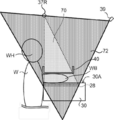
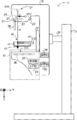
- the radiation irradiation unit 37 includes a radiation source 37R having a radiation tube (not shown) that irradiates the imaging table 30 with radiation R. Further, the radiation irradiation unit 37 includes a collimator 33. By controlling the collimator 33 by the control unit 20, the irradiation region 70 of the radiation R is set as shown in FIG. 3, and the irradiation field 71 of the radiation R on the imaging surface 30A of the imaging table 30 is defined.
- FIG. 3 shows an example of the irradiation region 70 of the radiation R irradiated from the radiation source 37R in a state where the breast WB of the subject W photographed by the mammography apparatus 10 is compressed by the compression plate 40.
- the irradiation region 70 is a space in which the radiation R is irradiated from the radiation source 37R to the imaged object to be imaged by the mammography apparatus 10.
- the size and shape of the irradiation field 71 of the present embodiment are determined according to the size of the imaging surface (not shown) of the radiation detector 28, the size of the breast WB to be imaged, and the like, and the irradiation field 71 of the irradiation field 71.
- the control unit 20 controls the collimator 33 according to the size and shape.
- the shape of the irradiation field 71 is rectangular.
- the irradiation region 70 of the present embodiment is a quadrangular pyramid-shaped region having the focal point of the radiation tube (not shown) included in the radiation source 37R as the apex and the irradiation field 71 as the bottom surface.
- the imaging target in the present embodiment is the breast WB of the subject, but the imaging target is not limited to the breast WB, and includes those approved to be imaged on a radiographic image such as a marker.
- the compression plate 40 or the like which is recognized to be arranged in the imaging region of the radiographic image in the radiographic image capturing, is also regarded as an imaging target.
- an object other than the object to be imaged that invades the irradiation area 70 is referred to as a “foreign substance”.
- the foreign matter include a head WH of the subject W, a hand (not shown), and a foreign object other than the subject W.
- the radiation irradiation unit 37 is provided on the arm unit 32 together with the photographing table 30 and the compression unit 36.
- a face guard 38 for protecting the subject from the radiation R emitted from the radiation source 37R can be attached and detached at a position close to the subject of the arm portion 32 below the radiation irradiation portion 37. It is attached.
- a TOF (Time of Flight) camera 39 is provided at a position away from the subject of the arm portion 32, which is below the irradiation unit 37.
- the TOF camera 39 is a camera that uses the TOF method to capture a distance image representing a distance to a subject to be imaged.
- the TOF camera 39 of the present embodiment is an example of the photographing device and the distance image capturing device of the present disclosure. Specifically, the TOF camera 39 takes a picture with the TOF camera 39 based on the time until the object to be photographed is irradiated with light such as infrared rays and the reflected light is received, or the phase change between the emitted light and the received light. Measure the distance to the subject.
- the distance image captured by the TOF camera 39 has distance information representing the distance between the TOF camera 39 and the imaging target for each pixel.
- the distance image is an image from which the distance to the shooting target can be derived.
- the TOF camera 39 of the present embodiment is arranged so that the photographable area 72 includes the entire irradiation area 70. Therefore, the distance image taken by the TOF camera 39 includes an image corresponding to the irradiation region 70.
- the photographable area 72 is defined by design.
- the mammography apparatus 10 of the present embodiment includes an arm portion 32, a base 34, and a shaft portion 35.
- the arm portion 32 is movably held in the vertical direction (Z-axis direction) by the base 34.
- the shaft portion 35 connects the arm portion 32 to the base 34.
- the arm portion 32 is rotatable relative to the base 34 with the shaft portion 35 as the rotation axis.
- the arm portion 32 and the compression unit 36 can rotate separately with respect to the base 34 with the shaft portion 35 as the rotation axis.
- gears (not shown) are provided on the shaft portion 35, the arm portion 32, and the compression unit 36, respectively, and the arm portion 32 and the compression unit 36 are switched by switching between the meshed state and the non-engaged state of the gears.
- Each of the above is connected to the shaft portion 35.
- One or both of the arm portion 32 and the compression unit 36 connected to the shaft portion 35 rotate integrally with the shaft portion 35.
- the compression unit 36 is provided with a compression plate drive unit (not shown) that moves the compression plate 40 in the vertical direction (Z-axis direction).
- the compression plate 40 of the present embodiment has a function of pressing the breast of the subject.
- the support portion 46 of the compression plate 40 is detachably attached to the compression plate drive portion, moves in the vertical direction (Z-axis direction) by the compression plate drive portion, and presses the breast of the subject with the imaging table 30. ..
- the compression plate 40 of the present embodiment is an example of the compression member of the present disclosure.
- the compression plate 40 of the present embodiment includes a bottom portion 43, a wall portion 44, and a support portion 46, and the bottom portion 43 in contact with the breast of the subject is surrounded by the wall portion 44 in a cross section.
- the shape is concave.
- the compression plate 40 is not limited to the one that presses the entire breast, but may be the one that presses a part of the breast. In other words, the compression plate 40, which is smaller than the breast, may be used.
- a compression plate 40 for example, a compression plate 40 used for so-called spot imaging, which captures a radiographic image of only a region where a lesion exists, is known.
- the other type of compression plate 40 include a compression plate according to the size of the breast, a compression plate for axillary imaging, a compression plate for magnified imaging, and the like.
- the compression plate 40 is not limited to one using a plate-shaped member, and may be, for example, one using a film-shaped member.
- the console 12 of the present embodiment is performed by the user by the operation unit 56 and the like, and the shooting order and various information acquired from the RIS (Radiology Information System) 2 and the like via the wireless communication LAN (Local Area Network) and the like. It has a function of controlling the mammography apparatus 10 by using instructions and the like.
- RIS Radiology Information System
- LAN Local Area Network
- the console 12 of this embodiment is, for example, a server computer. As shown in FIG. 5, the console 12 includes a control unit 50, a storage unit 52, an I / F unit 54, an operation unit 56, and a display unit 58.
- the control unit 50, the storage unit 52, the I / F unit 54, the operation unit 56, and the display unit 58 are connected to each other via a bus 59 such as a system bus or a control bus so that various information can be exchanged.
- the control unit 50 of this embodiment controls the entire operation of the console 12.
- the control unit 50 includes a CPU 50A, a ROM 50B, and a RAM 50C.
- Various programs including the foreign matter detection processing program 51, which are executed by the CPU 50A, are stored in the ROM 50B in advance.
- the RAM 50C temporarily stores various data.
- the CPU 50A of the present embodiment is an example of the processor of the present disclosure
- the ROM 50B of the present embodiment is an example of the memory of the present disclosure.
- the foreign matter detection processing program 51 of the present embodiment is an example of the information processing program of the present disclosure.
- the storage unit 52 stores image data of a radiation image taken by the mammography apparatus 10 and various other information. Specific examples of the storage unit 52 include HDDs and SSDs.
- the operation unit 56 is used for the user to input instructions and various information related to taking a radiation image including an irradiation instruction of radiation R.
- the operation unit 56 is not particularly limited, and examples thereof include various switches, a touch panel, a touch pen, and a mouse.
- the display unit 58 displays various information.
- the operation unit 56 and the display unit 58 may be integrated into a touch panel display.
- the I / F unit 54 communicates various information with the mammography device 10 and the RIS2 by wireless communication or wired communication.
- the image data of the radiographic image taken by the mammography apparatus 10 is received by the console 12 from the mammography apparatus 10 by wireless communication or wired communication via the I / F unit 54.
- FIG. 6 shows a functional block diagram of an example of the functional configuration of the console 12 of the present embodiment.
- the console 12 includes a first acquisition unit 60, a second acquisition unit 62, and a detection unit 64.
- the CPU 50A of the control unit 50 executes the foreign matter detection processing program 51 stored in the ROM 50B, so that the CPU 50A detects the first acquisition unit 60, the second acquisition unit 62, and the detection unit 12. It functions as a unit 64.
- the first acquisition unit 60 has a function of acquiring information representing the irradiation area 70.
- the method by which the first acquisition unit 60 acquires the information representing the irradiation region 70 is not limited.
- the irradiation region 70 is determined according to the setting of the collimator 33 and the distance between the radiation source 37R and the imaging surface 30A of the imaging table 30.
- the setting of the collimator 33 and the distance between the radiation source 37R and the imaging surface 30A can be grasped by the mammography apparatus 10. Therefore, for example, first, the control unit 20 of the mammography apparatus 10 derives the irradiation region 70 based on the setting of the collimator 33 and the distance between the radiation source 37R and the imaging surface 30A.
- the first acquisition unit 60 may acquire the information representing the irradiation region 70 derived by the control unit 20 from the mammography apparatus 10.
- the console 12 acquires information indicating the setting of the collimator 33 and information indicating the distance between the radiation source 37R and the imaging surface 30A, and the console 12 uses the acquired information.
- the information representing the irradiation region 70 may be derived within the inside, and the first acquisition unit 60 may acquire the information representing the derived irradiation region 70.
- the information representing the irradiation area 70 acquired by the first acquisition unit 60 is output to the detection unit 64.
- the second acquisition unit 62 has a function of acquiring a distance image taken by the TOF camera 39.
- the second acquisition unit 62 of the present embodiment acquires image data representing a distance image taken by the TOF camera 39 from the TOF camera 39 via the I / F unit 24 and the I / F unit 54.
- the distance image acquired by the second acquisition unit 62 is output to the detection unit 64.
- the detection unit 64 has a function of detecting the presence or absence of foreign matter other than the image to be photographed in the irradiation area 70 based on the distance image.
- the detection unit 64 of the present embodiment derives the space between the imaging target and the radiation source 37R as the detection region 74 in the irradiation region 70, and the foreign matter in the derived detection region 74 is derived. Detects the presence or absence of.
- the detection region 74 of the present embodiment is the space from the upper surface (the surface on the radiation source 37R side) of the bottom 43 of the compression plate 40 to the radiation source 37R in the irradiation region 70. Is.
- the detection region 74 is determined according to the height H of the breast WB in a state of being compressed by the compression plate 40, the thickness of the bottom 43 of the compression plate 40, and the irradiation region 70.
- the detection region 74 of the present embodiment is determined by the height H of the breast WB in the state of being compressed by the compression plate 40, the size of the detection region 74 changes depending on the breast WB and the compression state thereof.
- the thickness of the bottom portion 43 is relatively thin, so that the thickness of the bottom portion 43 is ignored for convenience.
- the detection unit 64 of the present embodiment first acquires the thickness H of the breast WB in a state of being compressed by the compression plate 40.
- the method by which the detection unit 64 acquires the thickness H of the breast WB is not limited.
- a detection unit for detecting the movement amount of the compression plate 40 by the compression plate drive unit (not shown) provided in the compression unit 36 of the compression plate 40 is provided, and the movement amount of the compression plate 40 detected by this detection unit is provided.
- the thickness of the breast WB derived from the above may be acquired by the detection unit 64.
- the mammography apparatus 10 or the like is provided with a sensor or the like for detecting the height from the imaging surface 30A to the compression plate 40, that is, the thickness H of the breast WB, and the thickness H detected by this sensor is detected by the detection unit 64. May be the form acquired by.
- a marker or the like is provided in an area that does not overlap with the breast WB, such as the end of the compression plate 40, and the distance between the TOF camera 39 and the marker is measured based on the image of the marker reflected in the distance image, and the TOF camera 39 is used.
- the thickness H of the breast WB may be obtained by subtracting the distance between the TOF camera 39 and the marker from the distance between the image and the imaging surface 30A.
- the detection unit 64 derives the distance between the radiation source 37R and the bottom 43 by subtracting the thickness H of the breast WB from the distance between the radiation source 37R and the imaging surface 30A. Further, the detection unit 64 extracts a quadrangular pyramid having the apex of the irradiation region 70 as the radiation source 37R, the bottom portion 43 as the bottom surface, and the length of the perpendicular line as the distance between the radiation source 37R and the bottom portion 43.
- the detection region 74 is derived.
- the detection unit 64 corresponds to the distance between each position in the detection area 74 derived based on the position of the detection area 74 and the TOF camera 39, and the detection area 74 in the distance image acquired from the TOF camera 39.
- the presence or absence of foreign matter in the detection region 74 is detected based on the image to be used.
- the distance between the position in the detection area 74 and the TOF camera 39 can be obtained. More specifically, it is possible to obtain a pixel value (hereinafter, referred to as a pixel value of the detection area 74) when the position in the detection area 74 is represented by a distance image.
- the pixel value of the pixel representing the distance to the object in the distance image is any of the pixel values of each position in the detection area 74.
- FIG. 7B shows an example of a state in which the head WH of the subject W has invaded the detection region 74 as a foreign substance.
- the pixel value of the image corresponding to the detection area 74 in the distance image of the TOF camera 39 is the pixel value reflecting the distance measured by the infrared rays reflected by the head WH in the detection area 74. It becomes. Therefore, the detection unit 64 compares the pixel value of the image corresponding to the detection area 74 in the distance image acquired from the TOF camera 39 with the pixel value of each position in the detection area 74.
- the detection unit 64 determines that there is a foreign substance in the detection area 74. In this case, the detection unit 64 outputs a detection result indicating that there is a foreign substance.
- the detection unit 64 has a foreign object in the detection area 74. Judge that there is no. In the present embodiment, when it is determined that there is no foreign matter in the detection area 74, the detection unit 64 does not output the detection result, but unlike the present embodiment, even if the detection result indicating that there is no foreign matter is output. good.
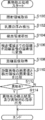
- the CPU 50A of the control unit 50 executes the foreign matter detection processing program 51 stored in the ROM 50B to execute the foreign matter detection processing shown in FIG. 8 as an example.
- FIG. 8 shows a flowchart showing an example of the flow of the foreign matter detection process executed on the console 12 of the present embodiment.
- the timing at which the CPU 50A executes the foreign matter detection process is not limited and can be any timing, for example, the timing at which the movement of the compression plate 40 is stopped, the timing at which the irradiation instruction of the radiation R is received, and the like. Can be mentioned.
- step S100 of FIG. 8 the first acquisition unit 60 acquires information representing the irradiation region 70 as described above.
- the detection unit 64 acquires the thickness H of the breast WB as described above. Further, in the next step S104, the detection unit 64 derives the detection region 74 based on the information representing the irradiation region 70 and the thickness H of the breast WB, as described above.
- the detection unit 64 converts the distance from the TOF camera 39 to each position of the detection area 74 into the pixel value of the distance image. Specifically, the distance between the TOF camera 39 and each position in the detection area 74 is converted into a pixel value of a distance image to derive a pixel value of each position in the detection area 74.
- the second acquisition unit 62 acquires a distance image from the TOF camera 39 as described above.
- the detection unit 64 compares the pixel value of the image corresponding to the detection area 74 in the distance image acquired from the TOF camera 39 with the pixel value of each position of the detection area 74. In the next step S112, the detection unit 64 determines whether or not there is a foreign substance in the detection area 74. As described above, when the pixel value of the image corresponding to the detection area 74 in the distance image is any of the pixel values of each position of the detection area 74, the detection unit 64 determines that there is a foreign substance in the detection area 74. to decide. When the detection unit 64 determines that there is a foreign substance, step S112 becomes an affirmative determination, and the process proceeds to step S114.
- the detection unit 64 outputs a detection result indicating that there is a foreign substance and an instruction for dealing with the foreign substance.
- the output destination of these detection results and the like is not particularly limited, and may be the display unit 58 of the console 12 or the display unit (not shown) of the mammography apparatus 10. Further, it may be output to a plurality of output destinations.
- the instruction for dealing with foreign substances is not limited, and examples thereof include an instruction for prohibiting irradiation of radiation R by the radiation source 36R. Further, for example, there is an instruction for outputting information for warning the user that there is a foreign substance in the detection area 74.
- the warning method is not limited, and for example, in addition to displaying the warning on the display unit 58, the warning may be given by sound, light, or the like.
- the detection unit 64 may further output information indicating the position and size of the foreign matter in the detection area 74.
- the position, size, and the like of the foreign matter can be specified from the positions of the pixels corresponding to the pixel values of the detection area 74 among the pixels of the image corresponding to the detection area 74 in the distance image.
- the type of the foreign matter may be discriminated based on the position and size of the detected foreign matter, and information indicating the type of the discriminated foreign matter may be output.
- the method of determining the type of foreign matter based on the position and size of the detected foreign matter is not particularly limited, and image analysis such as template matching using an image representing the foreign matter based on the assumed foreign matter can be performed.
- image analysis such as template matching using an image representing the foreign matter based on the assumed foreign matter can be performed.
- a form may be used in which a trained model trained by machine learning using images representing various assumed foreign substances is used.
- step S114 When the process of step S114 is completed in this way, the foreign matter detection process shown in FIG. 8 is completed. If the detection unit 64 determines that there is no foreign matter, step S112 results in a negative determination, and the foreign matter detection process shown in FIG. 8 ends.
- the console 12 of the present embodiment it is possible to detect whether or not there is a foreign substance in the detection area 74 based on the distance image taken by the TOF camera 39. Therefore, according to the console 12 of the present embodiment, even after the positioning is completed by the user or even if it is difficult for the user to see the irradiation area 70 of the radiation R, a foreign substance other than the object to be imaged in the irradiation area 70 of the radiation R. It is possible to appropriately detect the presence or absence of.
- the irradiation region 70 of the radiation source 37R and the imageable area 72 of the TOF camera 39 have been described.
- the imageable area 72 of the TOF camera 39 is irradiated.
- the region may be substantially the same as the irradiation region 70 of the source 37R.
- the mirror 82 provided in the mammography apparatus 10 reflects the infrared rays emitted from the TOF camera 39 and the infrared rays reflected by the photographing target or foreign matter and returned to the TOF camera 39.
- the photographable area 72 is substantially the same as the irradiation area 70.
- the mirror 82 may be retracted outside the irradiation area 70 when taking a radiation image. Further, when a material that transmits radiation R, for example, a filter used for photographing a radiation image is used as the mirror 82, the radiation image may be photographed while being arranged in the irradiation area 70 without being retracted. good.
- a material that transmits radiation R for example, a filter used for photographing a radiation image
- a mode for detecting whether or not there is a foreign substance in the detection area 74 has been described using a distance image taken by the TOF camera 39.
- a mode for detecting whether or not there is a foreign substance in the detection region 74 will be described using a visible light image taken by a visible light camera.
- the details of the configuration and operation of the mammography apparatus 10 and the console 12 of the present embodiment in the same manner as those of the first embodiment will be omitted.
- FIG. 10 shows a side view showing an example of the appearance of the mammography apparatus 10 of the present embodiment.
- the mammography apparatus 10 of the present embodiment includes a visible light camera 31 in place of the TOF camera 39 included in the mammography apparatus 10 of the first embodiment.
- the visible light camera 31 is a so-called general camera, and is a camera that captures a visible light image.
- the visible light camera 31 of the present embodiment is an example of the photographing device and the visible light image capturing device of the present disclosure. Specifically, the visible light camera 31 receives the visible light reflected by the imaging target, and captures a visible light image based on the received visible light. As shown in FIG. 10, the visible light camera 31 of the present embodiment is provided in the vicinity of the collimator 33 of the irradiation unit 37, and the imageable region of the visible light camera 31 includes the detection region 74.
- the console 12 of this embodiment has the same overall configuration (see FIG. 5) as that of the first embodiment, the description of the overall configuration will be omitted. On the other hand, since the functional configuration of the console 12 is different from that of the first embodiment, the functional configuration will be described.
- the console 12 of the present embodiment includes a first acquisition unit 60, a second acquisition unit 62, and a detection unit 64, similarly to the console 12 of the first embodiment (see FIG. 6).
- the function of the first acquisition unit 60 is the same as that of the first embodiment.
- the function of the second acquisition unit 62 is different from that of the first embodiment.
- the second acquisition unit 62 of the present embodiment has a function of acquiring a visible light image taken by the visible light camera 31.
- the second acquisition unit 62 of the present embodiment transfers image data representing a visible light image taken by the visible light camera 31 from the visible light camera 31 via the I / F unit 24 and the I / F unit 54. get.
- the visible light image acquired by the detection unit 64 is output to the detection unit 64.
- the detection unit 64 of the present embodiment has a function of detecting the presence or absence of a foreign substance other than the imaging target in the irradiation region 70 based on the visible light image.
- the detection unit 64 of the present embodiment derives and derives the space between the imaging target and the radiation source 37R as the detection region 74 in the irradiation area 70, similarly to the detection unit 64 of the first embodiment. The presence or absence of foreign matter in the detection area 74 is detected.
- a visible light image taken by the visible light camera 31 when there is no foreign matter in the detection area 74 is obtained in advance as a reference visible light image.
- the device for storing the reference visible light image is not limited, and may be stored in, for example, the storage unit 22 of the mammography device 10 or the storage unit 52 of the console 12.
- the detection unit 64 compares the image corresponding to the detection area 74 in the visible light image acquired from the visible light camera 31 with the image corresponding to the detection area 74 in the reference visible light image. Specifically, comparison is performed by deriving the difference between the pixel values of each image.
- the image corresponding to the detection area 74 in the visible light image acquired from the visible light camera 31 includes the image of the foreign substance.
- the difference from the pixel value of the pixel at the same position in the reference visible light image becomes large. Therefore, the detection unit 64 has an absolute difference between the pixel value of the image corresponding to the detection area 74 in the visible light image acquired from the visible light camera 31 and the pixel value of the image corresponding to the detection area 74 in the reference visible light image.
- FIG. 11 shows a flowchart showing an example of the flow of the foreign matter detection process executed on the console 12 of the present embodiment.
- the foreign matter detection process of the present embodiment includes the processes of steps S107 to S111 instead of steps S106 to S110 of the foreign matter detection process of the first embodiment (see FIG. 8).
- step S107 the detection unit 64 acquires a reference visible light image as described above.
- the second acquisition unit 62 acquires a visible light image from the visible light camera 31 as described above.
- the detection unit 64 compares the reference visible light image with the visible light image as described above. Based on the comparison result of this step, in the next step S112, the detection unit 64 determines whether or not there is a foreign substance in the detection area 74.
- the console 12 of the present embodiment it is possible to detect whether or not there is a foreign substance in the detection area 74 based on the visible light image taken by the visible light camera 31. Therefore, according to the console 12 of the present embodiment, even after the positioning is completed by the user or even if it is difficult for the user to see the irradiation area 70 of the radiation R, a foreign substance other than the object to be imaged in the irradiation area 70 of the radiation R. It is possible to appropriately detect the presence or absence of.
- the distance image taken by the TOF camera 39 and the distance image taken by the visible light camera 31 may be used to detect the presence or absence of foreign matter in the irradiation region 70.
- the detection unit 64 may issue a foreign matter handling instruction (see FIG. 8, step S114 of the foreign matter detection process).
- the irradiation region 70 may be photographed from different directions by the TOF camera 39 and the visible light camera 31, and the foreign matter may be detected from different directions.
- FIG. 12 shows a side view showing an example of the appearance of the mammography apparatus 10 of the present embodiment.
- the mammography apparatus 10 of the present embodiment is different from the mammography apparatus 10 of the second embodiment (see FIG. 10) in the position where the visible light camera 31 is provided.
- the visible light camera 31 of the present embodiment is provided on the subject W side of the irradiation unit 37.
- the imageable region 72 of the visible light camera 31 of the present embodiment includes the irradiation region 70 and includes the region provided with the compression plate 40. Further, the imageable region 72 of the visible light camera 31 of the present embodiment is defined as a region on the chest wall side of the breast WB of the subject W that can be imaged.
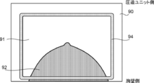
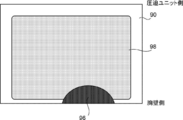
- FIG. 14 shows an example of a visible light image 90 taken by the visible light camera 31 of the present embodiment.
- the visible light image 90 taken by the visible light camera 31 includes an image corresponding to the compression plate 40.
- the bottom 43 of the compression plate 40 of the present embodiment is made of a transparent material, the breast WB is reflected in the bottom region 91 of the visible light image 90 corresponding to the bottom 43 of the compression plate 40. This results in a state in which the breast image 92 is included.
- the visible light image 90 shows the edge image 94 corresponding to the edge portion of the compression plate 40.
- the edge image 94 is an image showing the wall portion 44 of the bottom portion 43.
- the wall portion 44 of the compression plate 40 is more easily reflected in the visible light image 90 than the bottom portion 43. It is preferable that it is.
- the visible light image 90 is processed so that the bottom portion 43 and the wall portion 44 can be distinguished from each other.
- the edge portion of the compression plate 40 is emphasized as compared with the periphery.
- the material of the wall portion 44 may be a material that is easily reflected in the visible light image 90.
- the material of the wall portion 44 at least one of a material having a color different from that of the photographing table 30 and the breast WB, a phosphorescent material, and a fluorescent material may be used.
- the radiation source 37R side of the wall portion 44 of the compression plate 40 may be in a state where it can be easily reflected in the visible light image 90.
- at least one of a material having a color different from that of the photographing table 30 and the breast WB, a phosphorescent material, and a fluorescent material may be applied or attached to the surface of the wall portion 44 on the radiation source 37R side. good.
- various methods such as painting, sticking of members, coloring of the compression member on the material, and surface treatment can be adopted. Even if the bottom portion 43 and the wall portion 44 are made of materials having the same color, the apparent color may change depending on the thickness thereof.
- FIG. 15 shows a functional block diagram of an example of the functional configuration of the console 12 of the present embodiment.
- the console 12 of the present embodiment is different in that the console 12 of each of the above embodiments includes a third acquisition unit 66 instead of the first acquisition unit 60 (see FIG. 6).
- the third acquisition unit 66 has a function of acquiring compression member information indicating the type of the compression plate 40 attached to the compression unit 36.
- the size of the bottom 43 of the compression plate 40 of the present embodiment is determined according to the type of the compression plate 40. Therefore, the position and size of the edge image 94 included in the visible light image 90 are determined according to the type of the compression plate 40 attached to the compression unit 36.
- the support portion 46 of the compression plate 40 on the side attached to the compression unit 36 of the present embodiment is provided with a compression plate identifier (not shown) for identifying the type of the compression plate 40.
- the compression unit 36 is provided with an identifier sensor (not shown). The identifier sensor reads the compression plate identifier provided on the support portion 46 of the compression plate 40.
- the third acquisition unit 66 acquires the compression plate identifier read by the identifier sensor as the compression member information via the I / F unit 24 and the I / F unit 54.
- the compression member information acquired by the third acquisition unit 66 is output to the detection unit 64.
- the method by which the third acquisition unit 66 of the present embodiment acquires the compression member information is not limited to the above embodiment.
- the third acquisition unit 66 may acquire the type of photographing as the compression member information from the photographing menu or the like.
- the detection unit 64 of the present embodiment has a function of detecting the presence or absence of a foreign substance other than the imaging target in the irradiation region 70 based on the visible light image, as in the detection unit 64 of the second embodiment.
- the processing content required for is different.
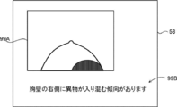
- the detection unit 64 of the present embodiment extracts the edge image 94 from the visible light image 90, and if the extracted edge image 94 is missing, determines that there is a foreign substance in the irradiation region 70. On the other hand, the detection unit 64 extracts the edge image 94 from the visible light image 90, and if the extracted edge image 94 is not missing, determines that there is no foreign matter in the irradiation region 70.
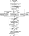
- FIG. 17 shows a flowchart showing an example of the flow of the foreign matter detection process executed on the console 12 of the present embodiment.
- step S200 the second acquisition unit 62 acquires the visible light image 90 from the visible light camera 31 as described above.
- the third acquisition unit 66 acquires the compression member information as described above.
- the detection unit 64 extracts the edge image 94 from the visible light image 90 acquired in the step S200 based on the compression member information acquired in the step S202.
- the specific method by which the detection unit 64 extracts the edge image 94 from the visible light image 90 is not particularly limited.
- the detection unit 64 may extract the edge image 94 by applying the existing image processing for edge detection.
- the detection unit 64 stores typical pattern data of the edge image 94 as a template in advance, and derives the similarity to the pattern data while searching the visible light image 90 with the template. Then, the detection unit 64 may extract the edge image 94 by applying template matching that considers that the edge image 94 exists at a place where the similarity is equal to or higher than the reference value and becomes the maximum.
- the detection unit 64 of the present embodiment estimates the shape and size of the edge image 94 according to the type of the compression plate 40 represented by the compression member information, and uses it for extracting the edge image 94. By estimating the shape and size of the edge image 94 according to the type of the compression plate 40 represented by the compression member information in this way, the edge image 94 can be extracted more accurately, and the processing for extraction is possible. The processing load on the above can be reduced.
- the detection unit 64 determines whether or not the edge image 94 extracted in the above step S204 has a chip.
- the detection unit 64 of the present embodiment determines whether or not there is a chip by comparing the reference edge image and the edge image 94.
- the visible light image 90 or the edge image 94 taken by the visible light camera 31 when there is no foreign matter in the irradiation region 70 is obtained in advance as the reference edge image.
- the device for storing the reference edge image is not limited, and may be stored in, for example, the storage unit 22 of the mammography device 10 or the storage unit 52 of the console 12.
- the detection unit 64 compares the edge image 94 extracted in step S204 with the reference edge image.
- the comparison is performed by deriving the difference between the pixel values of the extracted edge image 94 and the reference edge image. More specifically, there is a region in which a predetermined number or more of pixels in which the absolute value of the difference between the pixel value of the extracted edge image 94 and the pixel value of the reference edge image is larger than the chip detection threshold value are continuous. In this case, it is determined that the edge image 94 is chipped.
- the method by which the detection unit 64 determines whether or not the edge image 94 is chipped is not particularly limited. For example, when the outer peripheral line of the compression plate 40 recognized by the edge image 94 is interrupted by a predetermined number of pixels or more without using the reference edge image, the detection unit 64 has a chip in the edge image 94. It may be in the form of determining.
- step S206 If the edge image 94 is not chipped, the determination in step S206 becomes a negative determination, and the process proceeds to step S210. In this case, it corresponds to the case where there is no foreign matter in the irradiation area 70. On the other hand, if the edge image 94 is chipped, the determination in step S206 becomes an affirmative determination, and the process proceeds to step S208. In this case, it corresponds to the case where there is a foreign substance in the irradiation area 70.
- step S208 the detection unit 64 gives a detection result indicating the presence of foreign matter and an instruction for dealing with the foreign matter, as in S114 of the foreign matter detection processing (see FIGS. 8 and 11) of the first and second embodiments. After the output, the process proceeds to step S210.
- step S210 the detection unit 64 determines whether or not to end the foreign matter detection process being executed.
- the detection unit 64 of the present embodiment determines that the foreign matter detection process is terminated when the termination condition is satisfied. For example, as an end condition, there is a case where the user gives an irradiation instruction of radiation R by the operation unit 56 or the like. Further, for example, as an end condition, there is a case where the user instructs the end of the foreign matter detection process by the operation unit 56 or the like. If the end condition is not satisfied, the determination in step S210 becomes a negative determination, the process returns to step S200, and the above processes S200 to S208 are repeated.
- the user who recognizes that the foreign matter is present in the irradiation area 70 is in a state where the foreign matter has not invaded into the irradiation area 70 by maintaining the posture of the subject W or the like. Therefore, the above process is repeated to continue determining whether or not there is a foreign substance in the irradiation region 70.
- step S212 the detection unit 64 determines whether or not a foreign matter handling instruction is being given. Specifically, it is determined whether or not the process of step S208 has been performed. If the process of step S208 is not performed, in other words, if there is no foreign matter in the irradiation area 70, the determination of step S212 becomes a negative determination, and the foreign matter detection process shown in FIG. 17 ends. On the other hand, when the process of step S208 is performed, in other words, when there is a foreign substance in the irradiation area 70, the determination in step S212 becomes an affirmative determination, and the process proceeds to step S214.
- step S214 the detection unit 64 cancels the foreign matter handling instruction given in step S208. For example, when the detection unit 64 outputs information for warning the user that there is a foreign matter in the detection area 74 as an instruction for dealing with foreign matter, the warning is canceled by stopping the output of the information for warning. do.
- the process of step S214 is completed, the foreign matter detection process shown in FIG. 17 is completed.
- the foreign matter in the irradiation region 70 is based on the chipping of the image of the compression plate 40 included in the visible light image 90 taken by the visible light camera 31, particularly the chipping of the edge image 94. Detect the presence or absence. Therefore, according to the console 12 of the present embodiment, even after the positioning is completed by the user or even if it is difficult for the user to see the irradiation area 70 of the radiation R, a foreign substance other than the object to be imaged in the irradiation area 70 of the radiation R. It is possible to appropriately detect the presence or absence of.
- the detection unit 64 of this modification detects whether or not there is a chip in the region of the edge image 94 corresponding to the side of the subject W on the chest wall side.
- the mammography apparatus 10 can perform at least two types of photographing as the type of photographing a radiographic image. Specifically, the mammography apparatus 10 performs CC (Cranio-Caudal) imaging in which the imaging direction is the cranio-caudal direction with respect to the breast WB, and MLO (Medio-Lateral Oblique) in which the imaging direction is the medial-lateral oblique direction. At least two types of photography can be performed.
- CC Cirranio-Caudal
- MLO Medio-Lateral Oblique
- FIG. 18 shows an example of the states of the imaging table 30, the arm portion 32, and the radiation source 37R in CC imaging and MLO imaging.
- the imaging surface 30A is adjusted to face the upper side of the mammography apparatus 10 (the head WH side of the subject W) while facing the radiation source 37R. ..
- the radiation source 37R irradiates the breast WB with the radiation R from the head WH side to the foot side of the subject W, and CC imaging is performed.
- the detection unit 64 of this modification detects whether or not there is a defect in the region of the edge image 94 corresponding to the side of the subject W on the chest wall side when performing CC imaging.
- the arm portion 32 in the case of performing MLO imaging, is predetermined in the ⁇ direction or the + direction, for example, within a range of 45 degrees or more and less than 90 degrees, as compared with the case of performing CC imaging.
- the arm portion 32 is tilted with respect to the head-to-tail direction of the subject W by rotating it to a vertical angle. Specifically, when photographing the left breast, the arm portion 32 is tilted in the + direction with the imaging surface 30A and the radiation source 37R facing each other, and the imaging surface 30A is tilted to the right. ..
- the left side of the compression plate 40 is maintained in a state of being up and the right side is maintained in a state of being down.
- the left and right sides in this modification correspond to the left and right sides of the subject W facing the photographing table 30.
- foreign matter tends to easily enter from the upper side of the tilted photographing table 30. Therefore, foreign matter tends to easily enter from the upper side of the compression plate 40.
- the detection unit 64 of this modification detects whether or not there is a defect in the region of the edge image 94 corresponding to each of the chest wall side and the left side of the subject W when performing MLO imaging of the left breast WB. do.
- the arm portion 32 When photographing the right breast, the arm portion 32 is tilted in the minus direction with the imaging surface 30A and the radiation source 37R facing each other, and the imaging surface 30A is tilted to the left.
- the radiation R is irradiated from the radiation source 37R to the breast WB from the center side of the body of the subject W toward the outside (from between the breast WBs of the subject W toward the arm side), and MLO imaging is performed. Is done.
- the detection unit 64 of this modification detects whether or not there is a defect in the region of the edge image 94 corresponding to each side of the chest wall side and the right side of the subject W when performing MLO imaging of the right breast WB. do.
- FIG. 19 shows a flowchart showing an example of the flow of the foreign matter detection process executed on the console 12 of this modified example.
- the foreign matter detection process of the present modification shown in FIG. 19 includes the processes of steps S203A and S203B after step S202 of the foreign matter detection process (see FIG. 17) of the above-described embodiment, and the processes of steps S204A to S204C instead of step S204. The difference is that it has.
- the detection unit 64 determines whether or not the type of shooting is CC shooting.
- the method by which the detection unit 64 determines whether or not the type of imaging is CC imaging is not particularly limited.
- the type of shooting may be specified by referring to the shooting menu.
- step S203A When the type of shooting is CC shooting, the judgment in step S203A becomes an affirmative judgment, and the process proceeds to step S204A.
- step S204A as described above, the detection unit 64 detects whether or not there is a chip in the region of the edge image 94 corresponding to the side of the subject W on the chest wall side, and then proceeds to step S206.
- step S203A determines whether or not the image of the left breast WB is taken. In the case of photographing the left breast WB, the determination in step S203B becomes an affirmative determination, and the process proceeds to step S204B.
- step S204B the detection unit 64 detects whether or not there is a defect in the region of the edge image 94 corresponding to each side of the chest wall side and the left side of the subject W, and then proceeds to step S206.
- step S204C the detection unit 64 detects whether or not there is a defect in the region of the edge image 94 corresponding to each of the chest wall side and the right side of the subject W, and then proceeds to step S206.
- the entire edge image 94 is not used for detecting the presence or absence of foreign matter in the irradiation region 70, the foreign matter detection process can be performed faster and the processing load can be reduced. ..
- the compression plate 40 When a phosphorescent material is used for the edge portion of the compression plate 40, the compression plate 40 does not compress the subject W, does not irradiate the radiation R, and the compression plate 40 has a compression thickness. It is preferable to irradiate the edge portion with light for a certain period of time at a predetermined time interval to store the light in a state where the light is not applied. Further, when irradiating the phosphorescent material at the edge portion with light for phosphorescence, it is preferable that the compression plate 40 is located at a position away from the radiation source 37R. In other words, it is preferable to lower the height of the compression plate 40.
- the edge portion of the compression plate 40 corresponds to the wall portion 44 and has a height different from that of the bottom portion 43. Therefore, the edge portion is also taken from the distance image taken by the TOF camera 39 of the first embodiment. Image can be detected. Therefore, a distance image taken by the TOF camera 39 may be applied to the present embodiment instead of the visible light image 90.
- FIG. 20 shows a side view showing an example of the appearance of the mammography apparatus 10 of the present embodiment.
- the visible light camera 31 is provided at the same position as the mammography apparatus 10 of the third embodiment (see FIG. 12).
- the projector 29 is provided at a position of the arm portion 32 below the irradiation unit 37 and away from the subject W.
- the projector 29 of the present embodiment has a function of projecting the projected image 98 on the irradiation surface of the compression plate 40 to which the radiation R is irradiated.
- the projector 29 of the present embodiment has a function of projecting a projected image 98 on a surface (hereinafter, referred to as a projection surface 43A) on the bottom 43 of the compression plate 40 on which radiation R is irradiated.
- the projector 29 of the present embodiment is an example of the image projection device of the present disclosure.
- the projection surface 43A of the compression plate 40 is in a state where the projected image 98 can be easily displayed.
- the projection surface 43A may be formed by roughening the surface of the bottom 43 of the compression plate 40 on the radiation source 37R side.
- the projection surface 43A may be formed by attaching a specular reflection sheet to the surface of the compression plate 40.
- FIG. 22 shows an example of the visible light image 90 taken by the visible light camera 31 of the present embodiment.
- the visible light image 90 captured by the visible light camera 31 includes a projected image 98.
- the visible light image 90 includes an image of the projected image 98 displayed on the projection surface 43A, but for convenience of explanation, the projected image 98 is also included in the image due to the projected image 98 being reflected. That is.
- the projected image 98 included in the visible light image 90 of the present embodiment is an example of an image of a region corresponding to the irradiation field of the radiation of the present disclosure.
- FIG. 14 shows a functional block diagram of an example of the functional configuration of the console 12 of the present embodiment. As shown in FIG. 23, the console 12 of the present embodiment is different from the console 12 of each of the above embodiments (see FIG. 6 and the like) in that the projection control unit 68 is further provided.
- the projection control unit 68 has a function of controlling the projection image 98 to be projected onto the projector 29 in the area including the irradiation field 71 of the radiation R.
- the projected image 98 projected by the projector 29 and projected on the projection surface 43A of the compression plate 40 is the same as the range of the irradiation field 71 of the radiation R on the projection surface 43A of the compression plate 40.
- the position and size are used. Specifically, as shown in FIG. 21, the position and size of the projected image 98 are the same as the cross section of the irradiation region 70 on the projection surface 43A when the irradiation region 70 is blocked by the bottom 43.
- the projection control unit 68 has the same position and size of the projected image 98 on the projection surface 43A as the range of the irradiation field 71 of the radiation R on the projection surface 43A (hereinafter, simply referred to as “the range of the irradiation field 71”). And control for size. As described above, the size and shape of the irradiation field 71 are determined according to the size of the imaging surface (not shown) of the radiation detector 28, the size of the breast WB to be imaged, and the like. Therefore, as shown in FIG.
- the size and position of the range of the irradiation field 71 is the position of the radiation source 37R, that is, the distance between the radiation source 37R, which is a so-called SID (Source Image Distance), and the imaging surface of the radiation detector 28. It is determined according to h_s, the height h_c of the compression plate 40 corresponding to the thickness of the breast WB, and the distance h_d between the imaging surface 30A of the imaging table 30 and the imaging surface of the radiation detector 28.
- the thickness of the bottom 43 of the compression plate 40 is ignored, but more accurately, the value obtained by adding the thickness of the bottom 43 to the height h_c of the compression plate 40 is used. Further, when the projection surface 43A of the bottom portion 43 is provided with a specular reflection sheet or the like for displaying the projected image 98 as described above, a value obtained by further adding the thickness of the compression plate 40 mirror reflection sheet or the like is used.
- the projection control unit 68 of the present embodiment derives the position and size of the projected image 98 on the projection surface 43A by using the above equation (1).
- the coordinates, SID, and the like of the radiation source 37R required for using the above equation (1) are included in the information representing the irradiation area 70 acquired by the first acquisition unit.
- the projection control unit 68 controls the projector 29 to project the projected image 98 at the position and size of the projected image 98 on the derived projection surface 43A. Specifically, the projection control unit 68 outputs projected image projection information representing the position and size of the projected image 98 to the projector 29 via the I / F unit 54.
- the projector 29 projects the projected image 98 based on the projected image projection information input from the console 12.
- the method by which the projector 29 projects the projected image 98 based on the projected image projection information is not particularly limited. For example, a projected image 98 corresponding to the size and position of the imaging surface of the radiation detector 28 or the imaging surface 30A of the imaging table 30 is prepared in advance, and the prepared projected image 98 is based on the projected image projection information.
- the projected image data may be in the form of generating the projected image data for projecting the desired projected image 98 by trimming. Further, for example, the projected image data of a plurality of projected images 98 corresponding to each of the plurality of assumed positions and sizes are prepared in advance, and the projected image data of the projected image 98 according to the projected image projection information is prepared from the prepared images. May be used as a form for selecting.
- the image of the projected image 98 is not particularly limited, but it is preferable to use a single color, particularly a single color image different from the photographing surface 30A of the photographing table 30.
- the projected image 98 has the same position and size as the range of the irradiation field 71, but the position and size of the projected image 98 includes the range of the irradiation field 71.
- the size of the projected image 98 is larger than the range of the irradiation field 71, it is preferable to use the projected image 98 including an image representing the range of the irradiation field 71.
- the detection unit 64 of the present embodiment has a function of detecting the presence or absence of a foreign substance other than the imaging target in the irradiation region 70 based on the visible light image 90 acquired by the second acquisition unit, but the processing content required for the detection. Is different.
- FIG. 25 shows an example of the visible light image 90 taken by the visible light camera 31 with the projected image 98 projected on the projection surface 43A and the foreign matter invading the irradiation area 70. As shown in FIG. 25, the foreign matter image 96 is shown on the projected image 98 included in the visible light image 90.
- the detection unit 64 of the present embodiment detects whether or not the foreign matter image 96 is present on the projected image 98 included in the visible light image 90, and if the foreign matter image 96 is present on the projected image 98, it is irradiated. It is determined that there is a foreign substance in the area 70. On the other hand, when the foreign matter image 96 does not exist on the projected image 98 included in the visible light image 90, the detection unit 64 determines that there is no foreign matter in the irradiation region 70. Since the visible light image 90 captured by the visible light camera 31 is actually distorted by the lens of the visible light camera 31, the detection unit 64 considers the distortion caused by the lens and considers the distortion of the foreign matter in the irradiation region 70. It is preferable to detect the presence or absence.
- the detection unit 64 has the same range of the projected image 98 and the irradiation field 71 on the projection surface 43A, and the foreign matter image 96 is placed on the projected image 98 included in the visible light image 90. By detecting the presence or absence, it is possible to more accurately detect whether or not a foreign substance is present in the irradiation region 70.
- FIG. 26 shows a flowchart showing an example of the flow of the foreign matter detection process executed on the console 12 of the present embodiment.
- the foreign matter detection process of the present embodiment shown in FIG. 26 is different from the foreign matter detection process of the third embodiment (see FIG. 17) in that the process of steps S194 to S196 is provided before step S200.
- the projection control unit 68 first determines in step S194 whether or not to start the projection of the projected image 98.
- the projection of the visible light image 90 is started from the projector 29 when the predetermined projection start condition is satisfied.
- the projection start condition is not particularly limited, but for example, the presence or absence of a foreign substance in the irradiation region 70 is preferably detected after the positioning of the subject W is completed. Therefore, the projection start condition may be the case where the positioning of the subject W is completed. Can be mentioned. In this case, the form for determining that the positioning of the subject W is completed is not particularly limited.
- a predetermined time elapses after the movement of the compression plate 40 in the direction of pressing the breast WB is stopped or the movement speed becomes equal to or less than the threshold speed, or the height of the compression plate 40 does not change.
- a predetermined time has passed since then.
- a projection start condition for example, a case where the user instructs the start of projection by the operation unit 56 or the like can be mentioned.
- step S194 is a negative determination until the projection start condition is satisfied. On the other hand, when the projection start condition is satisfied, the determination in step S194 becomes an affirmative determination, and the process proceeds to step S196.
- step S196 the projection control unit 68 derives the position and size of the range of the irradiation field 71 on the projection surface 43A as described above.
- the projection control unit 68 of the present embodiment derives the coordinates of the projected image 98 on the projection surface 43A corresponding to the position and size of the range of the irradiation field 71 by using the above equation (1).
- the projection control unit 68 controls the projector 29 to project the projected image 98 according to the position and size of the range of the irradiation field 71 derived in the step S196, as described above.
- the projector 29 may project an image according to another purpose. For example, in order to support the positioning of the subject W, an image or the like representing the skin line of the breast WB when the ideal positioning is performed may be projected from the projector 29 on the projection surface 43A of the compression plate 40. In this way, when the projector 29 projects another image onto the projection surface 43A, the projection control unit 68 controls to end the projection of the other image and switch to the projection of the projected image 98.
- the mammography device 10 is provided with an irradiation field projection device (see FIG. 27) for displaying the range of the irradiation field 71 with visible light, and visible light is emitted from the irradiation field projection device toward the projection surface 43A. If so, the projection control unit 68 controls the irradiation field projection device to stop the irradiation of visible light.
- step S198 the visible light image 90 acquired by the second acquisition unit 62 in the next step S200 is in the state shown in FIG. 22 or the state shown in FIG. 25.
- the foreign matter detection process of the present embodiment is different in that it includes the foreign matter detection process (see FIG. 17) in the third embodiment and the process of step S207 instead of steps S204 and S206.
- step S207 the detection unit 64 determines whether or not there is a foreign substance in the irradiation area 70.
- the detection unit 64 of the present embodiment has a foreign matter in the irradiation region 70 depending on whether or not the foreign matter image 96 is present on the projection image 98 included in the visible light image 90 acquired in step S200. Judge whether or not.
- the specific method by which the detection unit 64 determines whether or not the foreign matter image 96 is present on the projected image 98 included in the visible light image 90 is not particularly limited. For example, a visible light image 90 (see FIG.
- the device for storing the reference projection image is not limited, and for example, it may be stored in the storage unit 22 of the mammography device 10 or may be stored in the storage unit 52 of the console 12.
- the detection unit 64 makes a comparison by deriving the difference between the pixel values of the projected image 98 included in the visible light image 90 and the projected image included in the reference projected image.
- a pixel in which the absolute value of the difference between the pixel value of the projected image 98 included in the visible light image 90 and the pixel value of the projected image included in the reference projected image is larger than the foreign matter detection threshold is predetermined. When there are more than a certain number of continuous regions, it is determined that there is a foreign substance in the irradiation region 70.
- the foreign matter detection process of the present embodiment is different in that the foreign matter detection process (see FIG. 17) in the third embodiment and the process of step S216 are provided after step S214.
- the projection control unit 68 controls the projector 29 to end the projection of the projected image 98. In response to this control, the projector 29 ends the projection of the projected image 98.
- the foreign matter detection process shown in FIG. 26 is completed.
- the projected image 98 is projected from the projector 29 onto the projection surface 43A of the compression plate 40, and the projected image 98 projected on the projection surface 43A by the visible light camera 31 is captured.
- the optical image 90 is acquired.
- the console 12 detects the presence or absence of foreign matter in the irradiation region 70 depending on whether or not the foreign matter image 96 is present on the projected image 98 included in the acquired visible light image 90. Therefore, according to the console 12 of the present embodiment, even after the positioning is completed by the user or even if it is difficult for the user to see the irradiation area 70 of the radiation R, a foreign substance other than the object to be imaged in the irradiation area 70 of the radiation R. It is possible to appropriately detect the presence or absence of.
- the mammography apparatus 10 of the present embodiment includes a visible light source 37V, and suggests an irradiation field 71 by projecting visible light V emitted from the visible light source 37V and reflected by the mirror 27. ..
- the visible light image 90 is acquired.
- the visible light image 90 can be acquired more clearly.
- the visible light image 90 obtained by capturing the projected image 98 projected from the projector 29 has been described, but the mammography device 10 includes an irradiation field projection device that indicates the range of the irradiation field 71 with visible light. If this is the case, a visible light image 90 obtained by capturing visible light indicating the range of the irradiation field 71 may be used instead of the projected image 98. Specifically, a visible light image 90 obtained by photographing a state in which visible light is irradiated on the projection surface 43A by an irradiation field projection device may be used.
- FIG. 27 shows a side view showing an example of the appearance of the mammography apparatus 10 in this case.
- the mammography apparatus 10 of the present embodiment includes a collimator 21, a mirror 27, and a visible light source 37V in place of the projector 29 of the mammography apparatus 10 (see FIG. 20) of the above embodiment.
- the collimator 21, the mirror 27, and the visible light source 37V of the present embodiment are examples of the irradiation field projection device of the present disclosure.
- the visible light source 37V lights up when a voltage is applied to generate visible light, and emits the generated visible light.
- the visible light source 37V is provided outside the irradiation region 70 of the radiation R.
- the mirror 27 reflects the visible light V emitted from the visible light source 37V toward the photographing surface 30A of the photographing table 30, thereby suggesting the irradiation field 71 of the radiation R by the visible light.
- the mirror 27 allows the radiation R emitted from the radiation source 37R to pass through.
- the collimator 21 has a function of limiting the radiation R and the irradiation field 71 of visible light. As shown in FIG. 27, the collimator 21 is provided between the mirror 27 and the photographing table 30. The irradiation field 71 is limited according to the opening of the collimator 21.
- the projection control unit 68 of the console 12 controls to project the projected image 98 from the projector 29, but instead of controlling the projection image 98 from the projector 29, it corresponds to the range from the visible light source 37V to the irradiation field 71. It suffices to control the irradiation of visible light.
- the visible light image 90 taken by the visible light camera 31 in a state where the projection surface 43A is irradiated with visible light from the visible light source 37V is projected instead of the projection image 98 included in the above-mentioned visible light image 90.
- An image corresponding to a region irradiated with visible light on the surface 43A (hereinafter, referred to as a “light irradiation field image”) is included. Therefore, instead of detecting whether or not the foreign matter image 96 is present on the projected image 98 included in the visible light image 90, the detection unit 64 detects the foreign matter on the light irradiation field image included in the visible light image 90. By detecting the presence or absence of the image 96, the presence or absence of foreign matter in the irradiation region 70 can be detected.
- the console 12 of each of the above forms includes a CPU 50A as at least one processor and a ROM 50B for storing instructions that can be executed by the CPU 50A.
- the CPU 50A is a TOF camera 39 or a TOF camera 39 having a region including an irradiation region 70, which is a space where radiation R is irradiated from the radiation source 37R to the breast WB of the subject imaged by the mammography apparatus 10, as a radiographic region (72).
- a distance image or a visible light image captured by the visible light camera 31 is acquired, and the presence or absence of a foreign substance other than the imaging target in the irradiation region 70 is detected based on the distance image or the visible light image.
- console 12 of each of the above forms it is possible to appropriately detect the presence or absence of a foreign substance other than the imaged object in the irradiation region 70 of the radiation R, so that the foreign substance is reflected in the radiation image captured by the mammography apparatus 10. It can suppress the crowding. As a result, re-shooting due to so-called photo loss can be suppressed.
- the detection unit 64 of the console 12 further detects whether or not the foreign matter is reflected in the photographed radiation image.
- the detection unit 64 may detect the foreign matter image included in the radiation image based on the position of the foreign matter image 96 detected from the distance image or the visible light image 90.
- the detection unit 64 may detect whether or not a foreign matter image is included in the radiographic image by using CAD (Computer-Aided Diagnosis). Further, when the radiographic image contains a foreign matter image, it is preferable to perform processing such as warning the user to that effect.
- the visible light image 90 or the distance image including the foreign matter image is associated with the position of the foreign matter image, the type of shooting, the information representing the user, the information representing the subject W, and the like, and accumulated as the foreign matter detection result information. You may leave it.
- the accumulated foreign matter detection result information By analyzing the accumulated foreign matter detection result information and performing statistical processing, for example, conditions for foreign matter to easily enter the irradiation region 70 are extracted for each user, each type of photographing, and each condition related to the subject W. be able to.
- FIG. 28 shows an example of the information displayed on the display unit 58 for supporting the positioning.
- a schematic diagram 99A and advice information 99B corresponding to typical foreign substances according to the extraction result are displayed on the display unit 58 as information for supporting positioning.
- Schematic diagram 99A is a diagram in which a foreign body image is superimposed on a breast schema diagram, a breast WB skin line image extracted from a radiographic image, a general breast diagram, or the like.
- the advice information 99B is information for presenting to the user a position or the like where a foreign substance tends to exist based on the extraction result.
- the user performs the positioning, it is possible to further suppress the invasion of foreign matter into the irradiation area 70 by displaying the information for supporting the positioning as shown in FIG. 28 on the display unit 58 or the like.
- the presence or absence of foreign matter in the irradiation region 70 is detected from the captured image captured by one imaging device, but the plurality of imaging devices are used and the imaging is performed by each of the plurality of imaging devices. It may be in the form of using the photographed image.
- TOF camera 39 1 may be in the form of using the two imaging devices 39 2.
- the one alone TOF camera 39 1 of the imaging region 72 1 and the TOF camera 39 2 of the imaging region 72 2 is useful if you do not fully encompass the irradiated region 70.
- the distance image captured by TOF camera 39 1, and a distance image captured by TOF camera 39 2, combined together position is used as a range images
- the presence or absence of foreign matter in the irradiation region 70 can be detected in the same manner as in the first embodiment.
- the TOF camera 39 is provided on the compression unit 36 side in the irradiation unit 37 of the mammography device 10
- a mode in which the visible light camera 31 is provided in the vicinity of the collimator 33 will be described.
- the positions where the TOF camera 39 and the visible light camera 31 are provided are not limited to this embodiment.
- Each of the TOF camera 39 and the visible light camera 31 may be arranged in a state in which the irradiation area 70 is included in the imageable area (photographable area 72) as described above, and the positions thereof are not limited.
- the TOF camera 39 may be provided on the face guard 38 side of the radiation irradiation unit 37.
- the TOF camera 39 or the visible light camera 31 may be provided outside the mammography apparatus 10. Further, for example, when both the TOF camera 39 and the visible light camera 31 are provided, the TOF camera 39 and the visible light camera 31 may be provided side by side at the same position or may be provided at different positions.
- a mode of capturing a distance image by a TOF method using a TOF camera has been described, but a distance image capturing device for capturing a distance image is a TOF camera.
- a distance image capturing device for capturing a distance image is a TOF camera.
- a form in which a distance image capturing device that irradiates a patterned infrared light to an imaging target and captures a distance image according to the reflected light from the imaging target is used, and a distance image is captured by applying the Structured Light method. May be.
- a DFD (Depth from Defocus) method for restoring the distance based on the degree of blurring of the edge region reflected in the distance image may be applied.
- a form using a distance image taken by a monocular camera using a color aperture filter is known.
- the form in which the mammography apparatus 10 is applied is described as an example of the radiation imaging apparatus of the present disclosure.
- the radiation imaging apparatus in the first and second embodiments is a mammography apparatus. Not limited to.
- it may be in the form of applying a radiographic imaging apparatus for performing general imaging.
- console 12 is an example of the information processing device of the present disclosure
- devices other than the console 12 may have the functions of the information processing device of the present disclosure.
- a part or all of the functions of the first acquisition unit 60, the second acquisition unit 62, and the detection unit 64 may be provided by, for example, a mammography device 10 or an external device other than the console 12.
- the hardware structure of the processing unit that executes various processes such as the first acquisition unit 60, the second acquisition unit 62, and the detection unit 64 is as follows.
- the various processors shown can be used.
- the various processors include a CPU, which is a general-purpose processor that executes software (program) and functions as various processing units, and a circuit after manufacturing an FPGA (Field Programmable Gate Array) or the like.
- Dedicated electricity which is a processor with a circuit configuration specially designed to execute specific processing such as programmable logic device (PLD), ASIC (Application Specific Integrated Circuit), which is a processor whose configuration can be changed. Circuits and the like are included.
- One processing unit may be composed of one of these various processors, or a combination of two or more processors of the same type or different types (for example, a combination of a plurality of FPGAs or a combination of a CPU and an FPGA). It may be composed of a combination). Further, a plurality of processing units may be configured by one processor.
- one processor is configured by a combination of one or more CPUs and software, as represented by a computer such as a client and a server.
- a processor functions as a plurality of processing units.
- SoC System On Chip
- the various processing units are configured by using one or more of the above-mentioned various processors as a hardware structure.
- an electric circuit in which circuit elements such as semiconductor elements are combined can be used.
- the foreign matter detection processing program 51 is provided in a form recorded on a recording medium such as a CD-ROM (Compact Disc Read Only Memory), a DVD-ROM (Digital Versatile Disc Read Only Memory), and a USB (Universal Serial Bus) memory. You may. Further, the foreign matter detection processing program 51 may be downloaded from an external device via a network.
- a recording medium such as a CD-ROM (Compact Disc Read Only Memory), a DVD-ROM (Digital Versatile Disc Read Only Memory), and a USB (Universal Serial Bus) memory. You may. Further, the foreign matter detection processing program 51 may be downloaded from an external device via a network.
Abstract
In the present invention, a CPU obtains a range image or a visible light image imaged by a TOF camera or a visible light camera with an imageable region that is a region including an irradiation region which is a space in a breast of a subject, imaged by a mammography device, that is irradiated with radiation from a radiation source, and detects whether there is a foreign substance other than the site to be imaged in the irradiation region on the basis of the range image or the visible light image.
Description
本開示は、情報処理装置、放射線画像撮影装置、情報処理方法、及び情報処理プログラムに関する。
This disclosure relates to an information processing device, a radiographic imaging device, an information processing method, and an information processing program.
放射線画像撮影装置による放射線画像の撮影において、放射線源から照射する放射線の照射領域に、例えば、被検体の撮影対象以外の部位等の異物が侵入した状態で放射線画像の撮影を行った場合、放射線画像の再撮影が必要になることがある。そのため、放射線画像の撮影において、可視光により示された放射線の照射範囲をユーザが確認することにより、放射線の照射領域に異物が存在するか否かを確認することが行われている。例えば、特開2018-157941号公報には、可視光により、放射線の照射野を示唆する技術が記載されている。
When a radiation image is taken by a radiation image capturing device, when the radiation image is taken in a state where a foreign substance such as a part other than the object to be photographed of the subject has invaded the irradiation area of the radiation emitted from the radiation source, the radiation is emitted. It may be necessary to retake the image. Therefore, in taking a radiation image, the user confirms the irradiation range of the radiation indicated by the visible light to confirm whether or not a foreign substance is present in the irradiation region of the radiation. For example, Japanese Patent Application Laid-Open No. 2018-157941 describes a technique for suggesting an irradiation field of radiation by visible light.
上記のように、従来から放射線の照射領域に侵入した異物の検出が行われているが、従来の技術では、放射線の照射領域に侵入した異物を検出するのには十分とは言えない場合がある。例えば、ユーザがポジショニングを確認した後、被検体が動いてしまうことにより撮影対象以外の被検体の部位が照射領域内に侵入してしまう場合がある。従来の技術ではこのような場合に対応できずに、再撮影が必要となる場合があった。
As described above, the detection of foreign matter that has invaded the radiation irradiation area has been conventionally performed, but the conventional technology may not be sufficient to detect the foreign matter that has invaded the radiation irradiation area. be. For example, after the user confirms the positioning, the subject may move and a part of the subject other than the imaging target may invade the irradiation area. In some cases, the conventional technique cannot cope with such a case, and re-shooting may be required.
本開示は、上記事情を考慮して成されたものであり、放射線の照射領域における撮影対象以外の異物の有無の検出を適切に行うことができる情報処理装置、情報処理方法、及び情報処理プログラムを提供する。
This disclosure has been made in consideration of the above circumstances, and is an information processing device, an information processing method, and an information processing program capable of appropriately detecting the presence or absence of a foreign substance other than the imaging target in the irradiation region of radiation. I will provide a.
本開示の第1の態様の情報処理装置は、少なくとも1つのプロセッサと、プロセッサによって実行可能な命令を記憶するメモリと、を備え、プロセッサは、放射線画像撮影装置で撮影される撮影対象に対して放射線源から放射線が照射される空間である照射領域を含む領域を撮影可能領域とする撮影装置により撮影された撮影画像を取得し、撮影画像に基づいて、照射領域における撮影対象以外の異物の有無を検出する。
The information processing apparatus of the first aspect of the present disclosure includes at least one processor and a memory for storing instructions that can be executed by the processor, and the processor is used for an imaging object imaged by the radiation imaging apparatus. An image taken by an imaging device whose area including the irradiation area, which is the space where radiation is emitted from the radiation source, is an imageable area is acquired, and the presence or absence of foreign matter other than the object to be imaged in the irradiation area is obtained based on the image. Is detected.
本開示の第2の態様の情報処理装置は、第1の態様の情報処理装置において、プロセッサは、照射領域を表す情報を取得し、情報によって表される照射領域における、異物の有無を検出する。
In the information processing apparatus of the second aspect of the present disclosure, in the information processing apparatus of the first aspect, the processor acquires information representing an irradiation region and detects the presence or absence of a foreign substance in the irradiation region represented by the information. ..
本開示の第3の態様の情報処理装置は、第1の態様または第2の態様の情報処理装置において、プロセッサは、照射領域のうち、撮影対象と放射線源との間の空間を検出領域として導出し、導出した検出領域における異物の有無を検出する。
The information processing apparatus of the third aspect of the present disclosure is the information processing apparatus of the first aspect or the second aspect, in which the processor uses the space between the imaging target and the radiation source as the detection region in the irradiation region. Derived and detect the presence or absence of foreign matter in the derived detection area.
本開示の第4の態様の情報処理装置は、第3の態様の情報処理装置において、放射線画像撮影装置は、被検体の乳房の放射線画像を撮影するマンモグラフィ装置であり、検出領域は、照射領域の内、乳房を圧迫する圧迫部材と放射線源との間の空間である。
The information processing apparatus according to the fourth aspect of the present disclosure is the information processing apparatus according to the third aspect. Of these, it is the space between the compression member that presses the breast and the radiation source.
本開示の第5の態様の情報処理装置は、第3の態様または第4の態様の情報処理装置において 撮影装置は、撮影対象との間の距離を表す距離画像を撮影画像として撮影する距離画像撮影装置である。
The information processing device of the fifth aspect of the present disclosure is the information processing device of the third aspect or the fourth aspect. It is a photographing device.
本開示の第6の態様の情報処理装置は、第5の態様の情報処理装置において、プロセッサは、距離画像における検出領域に対応する画像を用いて、検出領域における異物の有無を検出する。
In the information processing device of the sixth aspect of the present disclosure, in the information processing device of the fifth aspect, the processor detects the presence or absence of foreign matter in the detection area by using the image corresponding to the detection area in the distance image.
本開示の第7の態様の情報処理装置は、第6の態様の情報処理装置において、プロセッサは、検出領域の位置に基づいて導出された撮影装置と検出領域内の各位置との間の距離と、距離画像における検出領域に対応する画像が表す撮影装置と撮影対象との間の距離と、に基づいて、検出領域における異物の有無を検出する。
The information processing apparatus according to the seventh aspect of the present disclosure is the information processing apparatus according to the sixth aspect, wherein the processor is a distance between the photographing apparatus derived based on the position of the detection region and each position in the detection region. The presence or absence of foreign matter in the detection area is detected based on the distance between the photographing device and the photographing target represented by the image corresponding to the detection area in the distance image.
本開示の第8の態様の情報処理装置は、第5の態様から第7の態様のいずれか1態様の情報処理装置において、距離画像撮影装置は、TOF(Time Of Flight)方式を用いて距離画像を撮影する。
The information processing device according to the eighth aspect of the present disclosure is the information processing device according to any one of the fifth to seventh aspects, and the distance imaging device is a distance using a TOF (Time Of Flight) method. Take an image.
本開示の第9の態様の情報処理装置は、第1の態様から第4の態様のいずれか1態様の情報処理装置において、撮影装置は、撮影対象の可視光画像を撮影画像として撮影する可視光画像撮影装置である。
The information processing device according to the ninth aspect of the present disclosure is the information processing device according to any one of the first to fourth aspects, wherein the photographing device captures a visible light image to be photographed as a captured image. It is an optical image capturing device.
本開示の第10の態様の情報処理装置は、第1の態様の情報処理装置において、放射線画像撮影装置は、圧迫部材により圧迫状態にした乳房の放射線画像を撮影するマンモグラフィ装置であり、撮影装置は、撮影対象の可視光画像を撮影画像として撮影する可視光画像撮影装置であり、プロセッサは、撮影画像における圧迫部材の画像の欠けに基づいて、異物の有無を検出する。
The information processing apparatus according to the tenth aspect of the present disclosure is the information processing apparatus according to the first aspect. Is a visible light image capturing device that captures a visible light image to be captured as a captured image, and a processor detects the presence or absence of foreign matter based on the lack of an image of a compression member in the captured image.
本開示の第11の態様の情報処理装置は、第10の態様の情報処理装置において、プロセッサは、圧迫部材の画像における乳房にかかる被検体の欠けに基づいて、異物の有無を検出する。
In the information processing device of the eleventh aspect of the present disclosure, in the information processing device of the tenth aspect, the processor detects the presence or absence of a foreign substance based on the chipping of the subject on the breast in the image of the compression member.
本開示の第12の態様の情報処理装置は、第10の態様または第11の態様の情報処理装置において、プロセッサは、圧迫部材の画像として圧迫部材のエッジの部分の画像を用いる。
The information processing device of the twelfth aspect of the present disclosure is the information processing device of the tenth aspect or the eleventh aspect, and the processor uses an image of an edge portion of the compression member as an image of the compression member.
本開示の第13の態様の情報処理装置は、第12の態様の情報処理装置において、プロセッサは、圧迫部材の種類を表す圧迫部材情報を取得し、圧迫部材情報に基づいて、撮影画像に含まれるエッジの部分の画像の位置及び大きさの少なくとも一方を推定する。
In the information processing device of the thirteenth aspect of the present disclosure, in the information processing device of the twelfth aspect, the processor acquires the compression member information indicating the type of the compression member, and includes the compression member information in the captured image based on the compression member information. Estimate at least one of the position and size of the image of the edge portion to be processed.
本開示の第14の態様の情報処理装置は、第12の態様または第13の態様の情報処理装置において、圧迫部材のエッジの部分は、圧迫部材における乳房を圧迫する圧迫面及び乳房を載置する撮影台の少なくとも一方と異なる色であり、プロセッサは、エッジの部分の色に基づいて、撮影画像から圧迫部材のエッジの部分の画像を抽出する。
The information processing apparatus according to the fourteenth aspect of the present disclosure is the information processing apparatus according to the twelfth or thirteenth aspect. The color is different from at least one of the imaging tables to be processed, and the processor extracts an image of the edge portion of the compression member from the captured image based on the color of the edge portion.
本開示の第15の態様の情報処理装置は、第12の態様または第13の態様の情報処理装置において、圧迫部材のエッジの部分は、撮影画像において圧迫部材における乳房を圧迫する圧迫面の画像とは区別可能であるような加工がなされており、プロセッサは、撮影画像からエッジの部分の画像を抽出する。
The information processing apparatus according to the fifteenth aspect of the present disclosure is the information processing apparatus according to the twelfth aspect or the thirteenth aspect. The processing is performed so as to be distinguishable from the above, and the processor extracts the image of the edge portion from the captured image.
本開示の第16の態様の情報処理装置は、第15の態様の情報処理装置において、圧迫部材のエッジの部分は、蓄光材料及び蛍光材料の少なくとも一方により強調されている。
In the information processing apparatus of the 16th aspect of the present disclosure, in the information processing apparatus of the 15th aspect, the edge portion of the compression member is emphasized by at least one of the phosphorescent material and the fluorescent material.
本開示の第17の態様の情報処理装置は、第10の態様から第16の態様のいずれか1態様の情報処理装置において、プロセッサは、圧迫部材の画像のうち撮影の種類に応じた領域の画像の欠けに基づいて、異物の有無を検出する。
The information processing apparatus according to the seventeenth aspect of the present disclosure is the information processing apparatus according to any one of the tenth to sixteenth aspects. The presence or absence of foreign matter is detected based on the chipping of the image.
本開示の第18の態様の情報処理装置は、第1の態様の情報処理装置において、放射線画像撮影装置は、圧迫部材により圧迫状態にした乳房の放射線画像を撮影するマンモグラフィ装置であり、撮影装置は、圧迫部材における放射線が照射される照射面に画像投影装置により投影された投影画像を撮影した可視光画像を撮影画像として撮影する可視光画像撮影装置である。
The information processing apparatus according to the eighteenth aspect of the present disclosure is the information processing apparatus according to the first aspect. Is a visible light image capturing device that captures a visible light image obtained by capturing a projected image projected by an image projection device on an irradiation surface of a compression member that is irradiated with radiation as a captured image.
本開示の第19の態様の情報処理装置は、第18の態様の情報処理装置において、照射面に投影された投影画像は、放射線の照射野の範囲内に投影される。
The information processing apparatus of the 19th aspect of the present disclosure is the information processing apparatus of the 18th aspect, in which the projected image projected on the irradiation surface is projected within the range of the irradiation field of radiation.
本開示の第20の態様の情報処理装置は、第18の態様または第19の態様の情報処理装置において、照射面に投影された投影画像は、可視光により放射線の照射野の範囲を投影させる照射野投影装置により可視光が照射されない状態で放射線の照射野の範囲内に投影される。
In the information processing apparatus of the twentieth aspect of the present disclosure, in the information processing apparatus of the eighteenth aspect or the nineteenth aspect, the projected image projected on the irradiation surface causes the range of the irradiation field of radiation to be projected by visible light. It is projected within the range of the radiation field by the irradiation field projection device without irradiating visible light.
本開示の第21の態様の情報処理装置は、第18の態様から第20の態様のいずれか1態様の情報処理装置において、プロセッサは、撮影画像における放射線の照射野内に対応する領域の画像に基づいて、異物の有無を検出する。
The information processing apparatus according to the 21st aspect of the present disclosure is the information processing apparatus according to any one of the 18th to 20th aspects. Based on this, the presence or absence of foreign matter is detected.
本開示の第22の態様の情報処理装置は、第18の態様から第21の態様のいずれか1態様の情報処理装置において、プロセッサは、投影画像と、撮影画像とを比較した比較結果に基づいて、異物の有無を検出する。
The information processing apparatus according to the 22nd aspect of the present disclosure is based on the comparison result of comparing the projected image and the captured image in the information processing apparatus according to any one of the 18th to 21st aspects. To detect the presence or absence of foreign matter.
本開示の第23の態様の情報処理装置は、第18の態様から第21の態様のいずれか1態様の情報処理装置において、プロセッサは、放射線の照射野を含む領域に投影画像を投影させる制御を画像投影装置に対して行う。
The information processing apparatus according to the 23rd aspect of the present disclosure is the information processing apparatus according to any one of the 18th to 21st aspects, wherein the processor controls to project a projected image onto a region including an irradiation field of radiation. Is performed on the image projection device.
本開示の第24の態様の情報処理装置は、第23の態様の情報処理装置において、プロセッサは、圧迫部材の高さに応じて、圧迫部材の照射面における照射野の大きさ及び位置を導出し、導出した照射野の大きさ及び位置に応じて投影画像を投影させる制御を行う。
In the information processing apparatus of the 24th aspect of the present disclosure, in the information processing apparatus of the 23rd aspect, the processor derives the size and position of the irradiation field on the irradiation surface of the compression member according to the height of the compression member. Then, control is performed to project the projected image according to the size and position of the derived irradiation field.
本開示の第25の態様の情報処理装置は、第1の態様の情報処理装置において、放射線画像撮影装置は、圧迫部材により圧迫状態にした乳房の放射線画像を撮影するマンモグラフィ装置であり、撮影装置は、可視光により放射線の照射野の範囲を投影させる照射野投影装置により、圧迫部材に照射野の範囲が投影されている状態を撮影画像として撮影する可視光画像撮影装置である。
The information processing apparatus according to the 25th aspect of the present disclosure is the information processing apparatus according to the first aspect. Is a visible light image capturing device that captures a state in which the range of the irradiation field is projected on the compression member as a captured image by the irradiation field projection device that projects the range of the irradiation field of radiation with visible light.
本開示の第26の態様の情報処理装置は、第1の態様から第25の態様のいずれか1態様の情報処理装置において、プロセッサは、異物が有ることを検出した場合、放射線源による放射線の照射を禁止する。
The information processing apparatus according to the 26th aspect of the present disclosure is the information processing apparatus according to any one of the first to the twenty-fifth aspects. Irradiation is prohibited.
本開示の第27の態様の情報処理装置は、第1の態様から第26の態様のいずれか1態様の情報処理装置において、プロセッサは、異物が有ることを検出した場合、異物に関する警告を出力する。
In the information processing device according to the 27th aspect of the present disclosure, in the information processing device according to any one of the first to 26th aspects, when the processor detects the presence of a foreign substance, the processor outputs a warning regarding the foreign substance. do.
本開示の第28の態様の情報処理装置は、第1の態様から第27の態様のいずれか1態様の情報処理装置において、撮影装置は複数有り、複数の撮影装置の各々の撮影可能領域が組み合わされた、複数の撮影装置全体での撮影可能領域が、照射領域を含む。
The information processing apparatus according to the 28th aspect of the present disclosure is the information processing apparatus according to any one of the first to 27th aspects. The combined imageable area of the entire plurality of imaging devices includes the irradiation area.
本開示の第29の態様の放射線画像撮影装置は、本開示の情報処理装置と、撮影装置値と、を備える。
The radiographic imaging apparatus according to the 29th aspect of the present disclosure includes the information processing apparatus of the present disclosure and the imaging apparatus value.
また、上記目的を達成するために本開示の第30の態様の情報処理方法は、放射線画像撮影装置で撮影される撮影対象に対して放射線源から放射線が照射される空間である照射領域を含む領域を撮影可能領域とする撮影装置により撮影された撮影画像を取得し、撮影画像に基づいて、照射領域における撮影対象以外の異物の有無を検出する処理をコンピュータが実行するための方法である。
Further, in order to achieve the above object, the information processing method according to the thirtieth aspect of the present disclosure includes an irradiation region which is a space in which radiation is emitted from a radiation source to an imaged object photographed by a radiation imaging apparatus. This is a method for a computer to acquire a photographed image taken by a photographing apparatus having an area as a photographable area and to detect the presence or absence of foreign matter other than the imaged object in the irradiated area based on the photographed image.
本開示の第31の態様の情報処理プログラムは、放射線画像撮影装置で撮影される撮影対象に対して放射線源から放射線が照射される空間である照射領域を含む領域を撮影可能領域とする撮影装置により撮影された撮影画像を取得し、撮影画像に基づいて、照射領域における撮影対象以外の異物の有無を検出する処理をコンピュータに実行させるためのものである。
The information processing program according to the 31st aspect of the present disclosure is an imaging apparatus in which an region including an irradiation region, which is a space in which radiation is emitted from a radiation source to an imaging target photographed by the radiation imaging apparatus, is an imageable area. This is for causing a computer to perform a process of acquiring a photographed image photographed by the above and detecting the presence or absence of a foreign substance other than the imaged object in the irradiation area based on the photographed image.
本開示によれば、放射線の照射領域における撮影対象以外の異物の有無の検出を適切に行うことができる。
According to the present disclosure, it is possible to appropriately detect the presence or absence of foreign matter other than the imaging target in the irradiation region of radiation.
以下、図面を参照して本発明の実施形態を詳細に説明する。なお、各実施形態は本発明を限定するものではない。
Hereinafter, embodiments of the present invention will be described in detail with reference to the drawings. It should be noted that each embodiment does not limit the present invention.
[第1実施形態]
まず、本実施形態の放射線画像撮影システムにおける、全体の構成の一例について説明する。図1には、本実施形態の放射線画像撮影システム1における、全体の構成の一例を表す構成図が示されている。図1に示すように、本実施形態の放射線画像撮影システム1は、マンモグラフィ装置10及びコンソール12を備える。本実施形態のマンモグラフィ装置10が、本開示の放射線画像撮影装置の一例である。また、本実施形態のコンソール12が、本開示の情報処理装置の一例である。 [First Embodiment]
First, an example of the overall configuration of the radiation imaging system of the present embodiment will be described. FIG. 1 shows a configuration diagram showing an example of the overall configuration of the radiation imaging system 1 of the present embodiment. As shown in FIG. 1, the radiographic imaging system 1 of the present embodiment includes amammography apparatus 10 and a console 12. The mammography apparatus 10 of the present embodiment is an example of the radiographic imaging apparatus of the present disclosure. Further, the console 12 of the present embodiment is an example of the information processing apparatus of the present disclosure.
まず、本実施形態の放射線画像撮影システムにおける、全体の構成の一例について説明する。図1には、本実施形態の放射線画像撮影システム1における、全体の構成の一例を表す構成図が示されている。図1に示すように、本実施形態の放射線画像撮影システム1は、マンモグラフィ装置10及びコンソール12を備える。本実施形態のマンモグラフィ装置10が、本開示の放射線画像撮影装置の一例である。また、本実施形態のコンソール12が、本開示の情報処理装置の一例である。 [First Embodiment]
First, an example of the overall configuration of the radiation imaging system of the present embodiment will be described. FIG. 1 shows a configuration diagram showing an example of the overall configuration of the radiation imaging system 1 of the present embodiment. As shown in FIG. 1, the radiographic imaging system 1 of the present embodiment includes a
まず、本実施形態のマンモグラフィ装置10について説明する。図2には、本実施形態のマンモグラフィ装置10の外観の一例を表す側面図が示されている。なお、図2は、被検体の右側からマンモグラフィ装置10を見た場合の外観の一例を示している。
First, the mammography apparatus 10 of the present embodiment will be described. FIG. 2 shows a side view showing an example of the appearance of the mammography apparatus 10 of the present embodiment. Note that FIG. 2 shows an example of the appearance when the mammography apparatus 10 is viewed from the right side of the subject.
本実施形態のマンモグラフィ装置10は、被検体の乳房を被写体として、乳房に放射線R(例えば、X線)を照射して乳房の放射線画像を撮影する装置である。なお、マンモグラフィ装置10は、被検体が起立している状態(立位状態)のみならず、被検体が椅子(車椅子を含む)等に座った状態(座位状態)において、被検体の乳房を撮影する装置であってもよい。
The mammography apparatus 10 of the present embodiment is an apparatus that takes a breast of a subject as a subject and irradiates the breast with radiation R (for example, X-ray) to take a radiographic image of the breast. The mammography apparatus 10 photographs the breast of the subject not only when the subject is standing (standing position) but also when the subject is sitting on a chair (including a wheelchair) or the like (sitting state). It may be a device that does.
図2に示すように、本実施形態のマンモグラフィ装置10は、撮影台30内部に制御部20、記憶部22、及びI/F(Interface)部24を備える。制御部20は、コンソール12の制御に応じて、マンモグラフィ装置10の全体の動作を制御する。制御部20は、いずれも図示を省略した、CPU(Central Processing Unit)、ROM(Read Only Memory)、及びRAM(Random Access Memory)を備える。ROMには、CPUで実行される、放射線画像の撮影に関する制御を行うための撮影処理プログラムを含む各種のプログラム等が予め記憶されている。RAMは、各種データを一時的に記憶する。
As shown in FIG. 2, the mammography apparatus 10 of the present embodiment includes a control unit 20, a storage unit 22, and an I / F (Interface) unit 24 inside the photographing table 30. The control unit 20 controls the overall operation of the mammography apparatus 10 according to the control of the console 12. The control unit 20 includes a CPU (Central Processing Unit), a ROM (Read Only Memory), and a RAM (Random Access Memory), all of which are not shown. The ROM stores in advance various programs and the like, which are executed by the CPU and include an imaging processing program for controlling the imaging of radiographic images. The RAM temporarily stores various data.
記憶部22には、放射線検出器28により撮影された放射線画像の画像データや、その他の各種情報等が記憶される。記憶部22の具体例としては、HDD(Hard Disk Drive)やSSD(Solid State Drive)等が挙げられる。I/F部24は、無線通信または有線通信により、コンソール12との間で各種情報の通信を行う。マンモグラフィ装置10で放射線検出器28により撮影された放射線画像の画像データは、I/F部24を介してコンソール12に無線通信または有線通信によって送信される。
The storage unit 22 stores image data of a radiation image taken by the radiation detector 28, various other information, and the like. Specific examples of the storage unit 22 include HDD (Hard Disk Drive) and SSD (Solid State Drive). The I / F unit 24 communicates various information with the console 12 by wireless communication or wired communication. The image data of the radiation image taken by the radiation detector 28 by the mammography apparatus 10 is transmitted to the console 12 via the I / F unit 24 by wireless communication or wired communication.
また、操作部26は、例えば、マンモグラフィ装置10の撮影台30等に複数のスイッチとして設けられている。なお、操作部26は、タッチパネル式のスイッチとして設けられていてもよいし、ユーザが足で操作するフットスイッチとして設けられていてもよい。
Further, the operation unit 26 is provided as a plurality of switches on, for example, the imaging table 30 of the mammography apparatus 10. The operation unit 26 may be provided as a touch panel type switch, or may be provided as a foot switch operated by the user with his / her foot.
放射線検出器28は、被写体である乳房を通過した放射線Rを検出する。図2に示すように、放射線検出器28は、撮影台30の内部に配置されている。本実施形態のマンモグラフィ装置10では、撮影を行う場合、撮影台30の撮影面30A上には、被検体の乳房が医師及び技師等のユーザによってポジショニングされる。
The radiation detector 28 detects the radiation R that has passed through the breast, which is the subject. As shown in FIG. 2, the radiation detector 28 is arranged inside the photographing table 30. In the mammography apparatus 10 of the present embodiment, when imaging is performed, the breast of the subject is positioned on the imaging surface 30A of the imaging table 30 by a user such as a doctor or a technician.
放射線検出器28は、被検体の乳房及び撮影台30を透過した放射線Rを検出し、検出した放射線Rに基づいて放射線画像を生成し、生成した放射線画像を表す画像データを出力する。本実施形態の放射線検出器28の種類は、特に限定されず、例えば、放射線Rを光に変換し、変換した光を電荷に変換する間接変換方式の放射線検出器であってもよいし、放射線Rを直接電荷に変換する直接変換方式の放射線検出器であってもよい。
The radiation detector 28 detects the radiation R transmitted through the subject's breast and the imaging table 30, generates a radiation image based on the detected radiation R, and outputs image data representing the generated radiation image. The type of the radiation detector 28 of the present embodiment is not particularly limited, and may be, for example, an indirect conversion type radiation detector that converts radiation R into light and converts the converted light into electric charge, or radiation. A direct conversion type radiation detector that directly converts R into an electric charge may be used.
放射線照射部37は、撮影台30に対して放射線Rを照射する放射線管(図示省略)を有する放射線源37Rを備えている。また、放射線照射部37は、コリメータ33を備えている。制御部20がコリメータ33を制御することにより、図3に示すように、放射線Rの照射領域70が設定され、撮影台30の撮影面30Aにおける放射線Rの照射野71が規定される。図3には、マンモグラフィ装置10で撮影される被検体Wの乳房WBを圧迫板40により圧迫した状態において、放射線源37Rから照射する放射線Rの照射領域70の一例を示す。照射領域70は、マンモグラフィ装置10で撮影される撮影対象に対して放射線源37Rから放射線Rが照射される空間である。なお、本実施形態の照射野71の大きさ及び形状は、放射線検出器28の撮影面(図示省略)の大きさや撮影対象である乳房WBの大きさ等に応じて定められ、照射野71の大きさ及び形状に応じて、制御部20がコリメータ33を制御する。一例として本実施形態では、照射野71の形状を矩形状としている。そのため、本実施形態の照射領域70は、放射線源37Rが有する放射線管(図示省略)の焦点を頂点、照射野71を底面とした四角錐状の領域となる。
The radiation irradiation unit 37 includes a radiation source 37R having a radiation tube (not shown) that irradiates the imaging table 30 with radiation R. Further, the radiation irradiation unit 37 includes a collimator 33. By controlling the collimator 33 by the control unit 20, the irradiation region 70 of the radiation R is set as shown in FIG. 3, and the irradiation field 71 of the radiation R on the imaging surface 30A of the imaging table 30 is defined. FIG. 3 shows an example of the irradiation region 70 of the radiation R irradiated from the radiation source 37R in a state where the breast WB of the subject W photographed by the mammography apparatus 10 is compressed by the compression plate 40. The irradiation region 70 is a space in which the radiation R is irradiated from the radiation source 37R to the imaged object to be imaged by the mammography apparatus 10. The size and shape of the irradiation field 71 of the present embodiment are determined according to the size of the imaging surface (not shown) of the radiation detector 28, the size of the breast WB to be imaged, and the like, and the irradiation field 71 of the irradiation field 71. The control unit 20 controls the collimator 33 according to the size and shape. As an example, in the present embodiment, the shape of the irradiation field 71 is rectangular. Therefore, the irradiation region 70 of the present embodiment is a quadrangular pyramid-shaped region having the focal point of the radiation tube (not shown) included in the radiation source 37R as the apex and the irradiation field 71 as the bottom surface.
なお、本実施形態における撮影対象は、被検体の乳房WBであるが、乳房WBに限定されず、マーカ等の放射線画像に画像が写ることを承認されたものも含む。また、本実施形態では、放射線画像の撮影において放射線画像の撮影領域内に配置されていることが認められている圧迫板40等についても、撮影対象とみなす。また、照射領域70内に侵入する撮影対象以外のものを「異物」という。異物としては、例えば、被検体Wの頭部WHや、手(図示省略)、及び被検体W以外の物が挙げられる。
The imaging target in the present embodiment is the breast WB of the subject, but the imaging target is not limited to the breast WB, and includes those approved to be imaged on a radiographic image such as a marker. Further, in the present embodiment, the compression plate 40 or the like, which is recognized to be arranged in the imaging region of the radiographic image in the radiographic image capturing, is also regarded as an imaging target. Further, an object other than the object to be imaged that invades the irradiation area 70 is referred to as a “foreign substance”. Examples of the foreign matter include a head WH of the subject W, a hand (not shown), and a foreign object other than the subject W.
図2に示すように放射線照射部37は、撮影台30及び圧迫ユニット36と共にアーム部32に設けられている。図2に示すように、放射線照射部37の下方にあたるアーム部32の被検体に近い位置には、放射線源37Rから出射された放射線Rから被検体を保護するためのフェイスガード38が着脱可能に取り付けられている。
As shown in FIG. 2, the radiation irradiation unit 37 is provided on the arm unit 32 together with the photographing table 30 and the compression unit 36. As shown in FIG. 2, a face guard 38 for protecting the subject from the radiation R emitted from the radiation source 37R can be attached and detached at a position close to the subject of the arm portion 32 below the radiation irradiation portion 37. It is attached.
また、放射線照射部37の下方にあたるアーム部32の被検体から離れた位置には、TOF(Time of Flight)カメラ39が設けられている。TOFカメラ39は、TOF方式を用いて、撮影対象との間の距離を表す距離画像を撮影するカメラである。本実施形態のTOFカメラ39が、本開示の撮影装置及び距離画像撮影装置の一例である。具体的には、TOFカメラ39は、撮影対象に赤外線等の光を照射し、その反射光を受光するまでの時間、または出射光と受光光との位相変化に基づいて、TOFカメラ39と撮影対象との間の距離を測定する。TOFカメラ39によって撮影される距離画像は、画素毎に、TOFカメラ39と撮影対象との間の距離を表す距離情報を有する。なお、距離画像とは、その画像から、撮影対象までの距離を導出することが可能な画像のことをいう。なお、本実施形態のTOFカメラ39は、図4に示すように、撮影可能領域72に照射領域70の全体が含まれる状態に配置されている。従って、TOFカメラ39により撮影された距離画像には、照射領域70に対応する画像が含まれる。なお、本実施形態のTOFカメラ39では、撮影可能領域72が、設計上定められている。
Further, a TOF (Time of Flight) camera 39 is provided at a position away from the subject of the arm portion 32, which is below the irradiation unit 37. The TOF camera 39 is a camera that uses the TOF method to capture a distance image representing a distance to a subject to be imaged. The TOF camera 39 of the present embodiment is an example of the photographing device and the distance image capturing device of the present disclosure. Specifically, the TOF camera 39 takes a picture with the TOF camera 39 based on the time until the object to be photographed is irradiated with light such as infrared rays and the reflected light is received, or the phase change between the emitted light and the received light. Measure the distance to the subject. The distance image captured by the TOF camera 39 has distance information representing the distance between the TOF camera 39 and the imaging target for each pixel. The distance image is an image from which the distance to the shooting target can be derived. As shown in FIG. 4, the TOF camera 39 of the present embodiment is arranged so that the photographable area 72 includes the entire irradiation area 70. Therefore, the distance image taken by the TOF camera 39 includes an image corresponding to the irradiation region 70. In the TOF camera 39 of the present embodiment, the photographable area 72 is defined by design.
また、図2に示すように本実施形態のマンモグラフィ装置10は、アーム部32と、基台34と、軸部35と、を備えている。アーム部32は、基台34によって、上下方向(Z軸方向)に移動可能に保持される。軸部35は、アーム部32を基台34に連結する。またアーム部32は、軸部35を回転軸として、基台34に対して相対的に回転可能となっている。
Further, as shown in FIG. 2, the mammography apparatus 10 of the present embodiment includes an arm portion 32, a base 34, and a shaft portion 35. The arm portion 32 is movably held in the vertical direction (Z-axis direction) by the base 34. The shaft portion 35 connects the arm portion 32 to the base 34. Further, the arm portion 32 is rotatable relative to the base 34 with the shaft portion 35 as the rotation axis.
アーム部32と圧迫ユニット36とは、軸部35を回転軸として、別々に、基台34に対して相対的に回転可能となっている。本実施形態では、軸部35、アーム部32、及び圧迫ユニット36にそれぞれギア(図示省略)が設けられ、このギア同士の噛合状態及び非噛合状態を切替えることにより、アーム部32及び圧迫ユニット36の各々が軸部35に連結される。軸部35に連結されたアーム部32及び圧迫ユニット36の一方または両方が、軸部35と一体に回転する。
The arm portion 32 and the compression unit 36 can rotate separately with respect to the base 34 with the shaft portion 35 as the rotation axis. In the present embodiment, gears (not shown) are provided on the shaft portion 35, the arm portion 32, and the compression unit 36, respectively, and the arm portion 32 and the compression unit 36 are switched by switching between the meshed state and the non-engaged state of the gears. Each of the above is connected to the shaft portion 35. One or both of the arm portion 32 and the compression unit 36 connected to the shaft portion 35 rotate integrally with the shaft portion 35.
圧迫ユニット36には、圧迫板40を上下方向(Z軸方向)に移動する圧迫板駆動部(図示省略)が設けられている。本実施形態の圧迫板40は、被検体の乳房を圧迫する機能を有する。圧迫板40の支持部46は、圧迫板駆動部に着脱可能に取り付けられ、圧迫板駆動部により上下方向(Z軸方向)に移動し、撮影台30との間で被検体の乳房を圧迫する。本実施形態の圧迫板40は、本開示の圧迫部材の一例である。
The compression unit 36 is provided with a compression plate drive unit (not shown) that moves the compression plate 40 in the vertical direction (Z-axis direction). The compression plate 40 of the present embodiment has a function of pressing the breast of the subject. The support portion 46 of the compression plate 40 is detachably attached to the compression plate drive portion, moves in the vertical direction (Z-axis direction) by the compression plate drive portion, and presses the breast of the subject with the imaging table 30. .. The compression plate 40 of the present embodiment is an example of the compression member of the present disclosure.
図2に示すように、本実施形態の圧迫板40は、底部43及び壁部44と、支持部46とを含み、被検体の乳房に接触する底部43が壁部44に囲まれた、断面形状が凹型に形成されている。
As shown in FIG. 2, the compression plate 40 of the present embodiment includes a bottom portion 43, a wall portion 44, and a support portion 46, and the bottom portion 43 in contact with the breast of the subject is surrounded by the wall portion 44 in a cross section. The shape is concave.
なお、マンモグラフィ装置10に取り付けが可能な圧迫板40には、複数の種類がある。例えば、圧迫板40は、乳房全体を圧迫するものに限らず、乳房の一部を圧迫するものであってもよい。換言すると、乳房よりも小さい圧迫板40でもよい。このような圧迫板40としては、例えば、病変が存在する領域のみの放射線画像を撮影する、いわゆるスポット撮影に用いられる圧迫板40が知られている。またその他の種類の圧迫板40としては、例えば、乳房の大きさに応じた圧迫板、腋窩撮影用の圧迫板、及び拡大撮影用の圧迫板等が挙げられる。また、便宜上「圧迫板」と称しているが、圧迫板40は、板状の部材を用いたものに限定されず、例えば、フィルム状の部材を用いたものであってもよい。
There are a plurality of types of compression plates 40 that can be attached to the mammography apparatus 10. For example, the compression plate 40 is not limited to the one that presses the entire breast, but may be the one that presses a part of the breast. In other words, the compression plate 40, which is smaller than the breast, may be used. As such a compression plate 40, for example, a compression plate 40 used for so-called spot imaging, which captures a radiographic image of only a region where a lesion exists, is known. Examples of the other type of compression plate 40 include a compression plate according to the size of the breast, a compression plate for axillary imaging, a compression plate for magnified imaging, and the like. Further, although it is referred to as a "compression plate" for convenience, the compression plate 40 is not limited to one using a plate-shaped member, and may be, for example, one using a film-shaped member.
一方、本実施形態のコンソール12は、無線通信LAN(Local Area Network)等を介してRIS(Radiology Information System)2等から取得した撮影オーダ及び各種情報と、操作部56等によりユーザにより行われた指示等とを用いて、マンモグラフィ装置10の制御を行う機能を有している。
On the other hand, the console 12 of the present embodiment is performed by the user by the operation unit 56 and the like, and the shooting order and various information acquired from the RIS (Radiology Information System) 2 and the like via the wireless communication LAN (Local Area Network) and the like. It has a function of controlling the mammography apparatus 10 by using instructions and the like.
本実施形態のコンソール12は、一例として、サーバーコンピュータである。図5に示すように、コンソール12は、制御部50、記憶部52、I/F部54、操作部56、及び表示部58を備えている。制御部50、記憶部52、I/F部54、操作部56、及び表示部58はシステムバスやコントロールバス等のバス59を介して相互に各種情報の授受が可能に接続されている。
The console 12 of this embodiment is, for example, a server computer. As shown in FIG. 5, the console 12 includes a control unit 50, a storage unit 52, an I / F unit 54, an operation unit 56, and a display unit 58. The control unit 50, the storage unit 52, the I / F unit 54, the operation unit 56, and the display unit 58 are connected to each other via a bus 59 such as a system bus or a control bus so that various information can be exchanged.
本実施形態の制御部50は、コンソール12の全体の動作を制御する。制御部50は、CPU50A、ROM50B、及びRAM50Cを備える。ROM50Bには、CPU50Aで実行される、異物検出処理プログラム51を含む各種のプログラム等が予め記憶されている。RAM50Cは、各種データを一時的に記憶する。本実施形態のCPU50Aが、本開示のプロセッサの一例であり、本実施形態のROM50Bが、本開示のメモリの一例である。また、本実施形態の異物検出処理プログラム51が、本開示の情報処理プログラムの一例である。
The control unit 50 of this embodiment controls the entire operation of the console 12. The control unit 50 includes a CPU 50A, a ROM 50B, and a RAM 50C. Various programs including the foreign matter detection processing program 51, which are executed by the CPU 50A, are stored in the ROM 50B in advance. The RAM 50C temporarily stores various data. The CPU 50A of the present embodiment is an example of the processor of the present disclosure, and the ROM 50B of the present embodiment is an example of the memory of the present disclosure. Further, the foreign matter detection processing program 51 of the present embodiment is an example of the information processing program of the present disclosure.
記憶部52には、マンモグラフィ装置10で撮影された放射線画像の画像データや、その他の各種情報等が記憶される。記憶部52の具体例としては、HDDやSSD等が挙げられる。
The storage unit 52 stores image data of a radiation image taken by the mammography apparatus 10 and various other information. Specific examples of the storage unit 52 include HDDs and SSDs.
操作部56は、放射線Rの照射指示を含む放射線画像の撮影等に関する指示や各種情報等をユーザが入力するために用いられる。操作部56は特に限定されるものではなく、例えば、各種スイッチ、タッチパネル、タッチペン、及びマウス等が挙げられる。表示部58は、各種情報を表示する。なお、操作部56と表示部58とを一体化してタッチパネルディスプレイとしてもよい。
The operation unit 56 is used for the user to input instructions and various information related to taking a radiation image including an irradiation instruction of radiation R. The operation unit 56 is not particularly limited, and examples thereof include various switches, a touch panel, a touch pen, and a mouse. The display unit 58 displays various information. The operation unit 56 and the display unit 58 may be integrated into a touch panel display.
I/F部54は、無線通信または有線通信により、マンモグラフィ装置10及びRIS2との間で各種情報の通信を行う。本実施形態の放射線画像撮影システム1では、マンモグラフィ装置10で撮影された放射線画像の画像データは、コンソール12が、I/F部54を介して無線通信または有線通信によりマンモグラフィ装置10から受信する。
The I / F unit 54 communicates various information with the mammography device 10 and the RIS2 by wireless communication or wired communication. In the radiographic image capturing system 1 of the present embodiment, the image data of the radiographic image taken by the mammography apparatus 10 is received by the console 12 from the mammography apparatus 10 by wireless communication or wired communication via the I / F unit 54.
さらに、図6には、本実施形態のコンソール12の機能的な構成の一例の機能ブロック図を示す。図6に示すようにコンソール12は、第1取得部60、第2取得部62、及び検出部64を備える。一例として本実施形態のコンソール12は、制御部50のCPU50AがROM50Bに記憶されている異物検出処理プログラム51を実行することにより、CPU50Aが、第1取得部60、第2取得部62、及び検出部64として機能する。
Further, FIG. 6 shows a functional block diagram of an example of the functional configuration of the console 12 of the present embodiment. As shown in FIG. 6, the console 12 includes a first acquisition unit 60, a second acquisition unit 62, and a detection unit 64. As an example, in the console 12 of the present embodiment, the CPU 50A of the control unit 50 executes the foreign matter detection processing program 51 stored in the ROM 50B, so that the CPU 50A detects the first acquisition unit 60, the second acquisition unit 62, and the detection unit 12. It functions as a unit 64.
第1取得部60は、照射領域70を表す情報を取得する機能を有する。なお、第1取得部60が照射領域70を表す情報を取得する方法は限定されない。照射領域70は、コリメータ33の設定、及び放射線源37Rと撮影台30の撮影面30Aとの間の距離に応じて定まる。コリメータ33の設定、及び放射線源37Rと撮影面30Aとの間の距離は、マンモグラフィ装置10において把握が可能である。そのため、例えば、まず、マンモグラフィ装置10の制御部20がコリメータ33の設定、及び放射線源37Rと撮影面30Aとの間の距離に基づいて照射領域70を導出する。そして、第1取得部60は、制御部20により導出された照射領域70を表す情報をマンモグラフィ装置10から取得してもよい。なお、本形態に限定されず、コンソール12がコリメータ33の設定を表す情報、及び放射線源37Rと撮影面30Aとの間の距離を表す情報を取得し、取得したこれらの情報を用いてコンソール12内で照射領域70を表す情報を導出し、導出された照射領域70を表す情報を第1取得部60が取得してもよい。第1取得部60により取得された照射領域70を表す情報は、検出部64に出力される。
The first acquisition unit 60 has a function of acquiring information representing the irradiation area 70. The method by which the first acquisition unit 60 acquires the information representing the irradiation region 70 is not limited. The irradiation region 70 is determined according to the setting of the collimator 33 and the distance between the radiation source 37R and the imaging surface 30A of the imaging table 30. The setting of the collimator 33 and the distance between the radiation source 37R and the imaging surface 30A can be grasped by the mammography apparatus 10. Therefore, for example, first, the control unit 20 of the mammography apparatus 10 derives the irradiation region 70 based on the setting of the collimator 33 and the distance between the radiation source 37R and the imaging surface 30A. Then, the first acquisition unit 60 may acquire the information representing the irradiation region 70 derived by the control unit 20 from the mammography apparatus 10. Not limited to this embodiment, the console 12 acquires information indicating the setting of the collimator 33 and information indicating the distance between the radiation source 37R and the imaging surface 30A, and the console 12 uses the acquired information. The information representing the irradiation region 70 may be derived within the inside, and the first acquisition unit 60 may acquire the information representing the derived irradiation region 70. The information representing the irradiation area 70 acquired by the first acquisition unit 60 is output to the detection unit 64.
第2取得部62は、TOFカメラ39により撮影された距離画像を取得する機能を有する。一例として本実施形態の第2取得部62は、TOFカメラ39により撮影された距離画像を表す画像データを、I/F部24及びI/F部54を介して、TOFカメラ39から取得する。第2取得部62が取得した距離画像は、検出部64に出力される。
The second acquisition unit 62 has a function of acquiring a distance image taken by the TOF camera 39. As an example, the second acquisition unit 62 of the present embodiment acquires image data representing a distance image taken by the TOF camera 39 from the TOF camera 39 via the I / F unit 24 and the I / F unit 54. The distance image acquired by the second acquisition unit 62 is output to the detection unit 64.
検出部64は、距離画像に基づいて、照射領域70における撮影対象以外の異物の有無を検出する機能を有する。一例として本実施形態の検出部64は、図7Aに示すように、照射領域70のうち、撮影対象と放射線源37Rとの間の空間を検出領域74として導出し、導出した検出領域74における異物の有無を検出する。図7Aに示すように、本実施形態の検出領域74は、具体的には、照射領域70のうち、圧迫板40の底部43の上面(放射線源37R側の面)から放射線源37Rまでの空間である。より具体的には、照射領域70のうち、乳房WBを圧迫する圧迫板40の底部43の上面から放射線源37Rまでの空間である。従って、検出領域74は、圧迫板40により圧迫された状態の乳房WBの高さHと、圧迫板40の底部43の厚みと、照射領域70とに応じて定められる。このように本実施形態の検出領域74は、圧迫板40により圧迫された状態の乳房WBの高さHにより定まるため、検出領域74の大きさは乳房WB及びその圧迫状態により変化する。なお、本実施形態では、底部43の厚みは、比較的薄いため、底部43の厚みについては便宜上、無視することとする。
The detection unit 64 has a function of detecting the presence or absence of foreign matter other than the image to be photographed in the irradiation area 70 based on the distance image. As an example, as shown in FIG. 7A, the detection unit 64 of the present embodiment derives the space between the imaging target and the radiation source 37R as the detection region 74 in the irradiation region 70, and the foreign matter in the derived detection region 74 is derived. Detects the presence or absence of. As shown in FIG. 7A, specifically, the detection region 74 of the present embodiment is the space from the upper surface (the surface on the radiation source 37R side) of the bottom 43 of the compression plate 40 to the radiation source 37R in the irradiation region 70. Is. More specifically, it is a space from the upper surface of the bottom 43 of the compression plate 40 that presses the breast WB to the radiation source 37R in the irradiation region 70. Therefore, the detection region 74 is determined according to the height H of the breast WB in a state of being compressed by the compression plate 40, the thickness of the bottom 43 of the compression plate 40, and the irradiation region 70. As described above, since the detection region 74 of the present embodiment is determined by the height H of the breast WB in the state of being compressed by the compression plate 40, the size of the detection region 74 changes depending on the breast WB and the compression state thereof. In the present embodiment, the thickness of the bottom portion 43 is relatively thin, so that the thickness of the bottom portion 43 is ignored for convenience.
一例として本実施形態の検出部64は、検出領域74を導出するため、まず、圧迫板40により圧迫された状態の乳房WBの厚みHを取得する。なお、検出部64が乳房WBの厚みHを取得する方法は限定されない。例えば、圧迫板40の圧迫ユニット36に設けられた圧迫板駆動部(図示省略)による圧迫板40の移動量を検出する検知部を設けておき、本検知部が検知した圧迫板40の移動量から導出された乳房WBの厚みを、検出部64が取得する形態としてもよい。また例えば、マンモグラフィ装置10等に、撮影面30Aから圧迫板40までの高さ、すなわち乳房WBの厚みHを検出するためのセンサ等を設けておき、本センサが検出した厚みHを検出部64が取得する形態としてもよい。また例えば、圧迫板40の端部等の乳房WBと重ならない領域にマーカ等を設けておき、距離画像に写るマーカの画像に基づいてTOFカメラ39とマーカとの距離を測定し、TOFカメラ39と撮影面30Aとの距離からTOFカメラ39とマーカとの距離を減算することで、乳房WBの厚みHを取得してもよい。
As an example, in order to derive the detection region 74, the detection unit 64 of the present embodiment first acquires the thickness H of the breast WB in a state of being compressed by the compression plate 40. The method by which the detection unit 64 acquires the thickness H of the breast WB is not limited. For example, a detection unit for detecting the movement amount of the compression plate 40 by the compression plate drive unit (not shown) provided in the compression unit 36 of the compression plate 40 is provided, and the movement amount of the compression plate 40 detected by this detection unit is provided. The thickness of the breast WB derived from the above may be acquired by the detection unit 64. Further, for example, the mammography apparatus 10 or the like is provided with a sensor or the like for detecting the height from the imaging surface 30A to the compression plate 40, that is, the thickness H of the breast WB, and the thickness H detected by this sensor is detected by the detection unit 64. May be the form acquired by. Further, for example, a marker or the like is provided in an area that does not overlap with the breast WB, such as the end of the compression plate 40, and the distance between the TOF camera 39 and the marker is measured based on the image of the marker reflected in the distance image, and the TOF camera 39 is used. The thickness H of the breast WB may be obtained by subtracting the distance between the TOF camera 39 and the marker from the distance between the image and the imaging surface 30A.
検出部64は、放射線源37Rと撮影面30Aとの間の距離から、乳房WBの厚みHを減算することにより、放射線源37Rと底部43との距離を導出する。また、検出部64は、照射領域70のうち、頂点を放射線源37Rとし、底部43を底面とし、垂線の長さを、放射線源37Rと底部43との距離とする四角錐を抽出することで検出領域74を導出する。
The detection unit 64 derives the distance between the radiation source 37R and the bottom 43 by subtracting the thickness H of the breast WB from the distance between the radiation source 37R and the imaging surface 30A. Further, the detection unit 64 extracts a quadrangular pyramid having the apex of the irradiation region 70 as the radiation source 37R, the bottom portion 43 as the bottom surface, and the length of the perpendicular line as the distance between the radiation source 37R and the bottom portion 43. The detection region 74 is derived.
さらに、検出部64は、検出領域74の位置に基づいて導出された検出領域74内の各位置とTOFカメラ39との間の距離と、TOFカメラ39から取得した距離画像における検出領域74に対応する画像とに基づいて、検出領域74における異物の有無を検出する。具体的には、TOFカメラ39の配置された位置、具体的には3次元上の座標が、予め解っているため、検出領域74内の位置とTOFカメラ39との間の距離が得られる。より具体的には、検出領域74内の位置を距離画像で表した場合の画素値(以下、検出領域74の画素値という)を得ることができる。検出領域74内に物体が存在する場合、距離画像におけるその物体までの距離を表す画素の画素値は、検出領域74内の各位置の画素値のいずれかとなる。
Further, the detection unit 64 corresponds to the distance between each position in the detection area 74 derived based on the position of the detection area 74 and the TOF camera 39, and the detection area 74 in the distance image acquired from the TOF camera 39. The presence or absence of foreign matter in the detection region 74 is detected based on the image to be used. Specifically, since the position where the TOF camera 39 is arranged, specifically the coordinates on the three dimensions are known in advance, the distance between the position in the detection area 74 and the TOF camera 39 can be obtained. More specifically, it is possible to obtain a pixel value (hereinafter, referred to as a pixel value of the detection area 74) when the position in the detection area 74 is represented by a distance image. When an object exists in the detection area 74, the pixel value of the pixel representing the distance to the object in the distance image is any of the pixel values of each position in the detection area 74.
図7Bには、被検体Wの頭部WHが異物として検出領域74に侵入した状態の一例を示している。図7Bに示した例では、TOFカメラ39の距離画像における検出領域74に対応する画像の画素値は、検出領域74内の頭部WHにより反射した赤外線により測定された距離が反映された画素値となる。そこで、検出部64は、TOFカメラ39から取得した距離画像における検出領域74に対応する画像の画素値と検出領域74内の各位置の画素値とを比較する。検出部64は、距離画像における検出領域74に対応する画像の画素値が、検出領域74内の各位置の画素値のいずれかである場合、検出領域74内に異物が有ると判断する。この場合、検出部64は、異物が有ることを表す検出結果を出力する。一方、検出部64は、TOFカメラ39から取得した距離画像における検出領域74に対応する画像の画素値が、検出領域74内の各位置の画素値のいずれでもない場合、検出領域74内に異物が無いと判断する。なお、本実施形態では、検出領域74内に異物が無いと判断した場合、検出部64は、検出結果を出力しないが、本形態と異なり、異物が無いことを表す検出結果を出力してもよい。
FIG. 7B shows an example of a state in which the head WH of the subject W has invaded the detection region 74 as a foreign substance. In the example shown in FIG. 7B, the pixel value of the image corresponding to the detection area 74 in the distance image of the TOF camera 39 is the pixel value reflecting the distance measured by the infrared rays reflected by the head WH in the detection area 74. It becomes. Therefore, the detection unit 64 compares the pixel value of the image corresponding to the detection area 74 in the distance image acquired from the TOF camera 39 with the pixel value of each position in the detection area 74. When the pixel value of the image corresponding to the detection area 74 in the distance image is any of the pixel values of each position in the detection area 74, the detection unit 64 determines that there is a foreign substance in the detection area 74. In this case, the detection unit 64 outputs a detection result indicating that there is a foreign substance. On the other hand, when the pixel value of the image corresponding to the detection area 74 in the distance image acquired from the TOF camera 39 is not any of the pixel values of each position in the detection area 74, the detection unit 64 has a foreign object in the detection area 74. Judge that there is no. In the present embodiment, when it is determined that there is no foreign matter in the detection area 74, the detection unit 64 does not output the detection result, but unlike the present embodiment, even if the detection result indicating that there is no foreign matter is output. good.
次に、本実施形態のコンソール12の作用について図面を参照して説明する。
Next, the operation of the console 12 of the present embodiment will be described with reference to the drawings.
本実施形態のコンソール12は、制御部50のCPU50Aが、ROM50Bに記憶されている異物検出処理プログラム51を実行することにより、図8に一例を示した異物検出処理を実行する。図8には、本実施形態のコンソール12において実行される異物検出処理の流れの一例を表したフローチャートが示されている。なお、CPU50Aが、異物検出処理を実行するタイミングは、限定されず、任意のタイミングとすることができ、例えば、圧迫板40の移動が停止したタイミングや、放射線Rの照射指示を受け付けたタイミング等が挙げられる。
In the console 12 of the present embodiment, the CPU 50A of the control unit 50 executes the foreign matter detection processing program 51 stored in the ROM 50B to execute the foreign matter detection processing shown in FIG. 8 as an example. FIG. 8 shows a flowchart showing an example of the flow of the foreign matter detection process executed on the console 12 of the present embodiment. The timing at which the CPU 50A executes the foreign matter detection process is not limited and can be any timing, for example, the timing at which the movement of the compression plate 40 is stopped, the timing at which the irradiation instruction of the radiation R is received, and the like. Can be mentioned.
図8のステップS100で第1取得部60は、上述したように、照射領域70を表す情報を取得する。次のステップS102で検出部64は、上述したように、乳房WBの厚みHを取得する。また、次のステップS104で検出部64は、上述したように、照射領域70を表す情報及び乳房WBの厚みHに基づいて、検出領域74を導出する。
In step S100 of FIG. 8, the first acquisition unit 60 acquires information representing the irradiation region 70 as described above. In the next step S102, the detection unit 64 acquires the thickness H of the breast WB as described above. Further, in the next step S104, the detection unit 64 derives the detection region 74 based on the information representing the irradiation region 70 and the thickness H of the breast WB, as described above.
次のステップS106で検出部64は、TOFカメラ39から検出領域74の各位置までの距離を距離画像の画素値に変換する。具体的には、TOFカメラ39と検出領域74内の各位置との間の距離を距離画像の画素値に変換して検出領域74の各位置の画素値を導出する。次のステップS108で第2取得部62は、上述したように、TOFカメラ39から距離画像を取得する。
In the next step S106, the detection unit 64 converts the distance from the TOF camera 39 to each position of the detection area 74 into the pixel value of the distance image. Specifically, the distance between the TOF camera 39 and each position in the detection area 74 is converted into a pixel value of a distance image to derive a pixel value of each position in the detection area 74. In the next step S108, the second acquisition unit 62 acquires a distance image from the TOF camera 39 as described above.
次のステップS110で検出部64は、上述したように、TOFカメラ39から取得した距離画像における検出領域74に対応する画像の画素値と、検出領域74の各位置の画素値とを比較する。次のステップS112で検出部64は、検出領域74に異物が有るか否かを判断する。上述したように、検出部64は、距離画像における検出領域74に対応する画像の画素値が、検出領域74の各位置の画素値のいずれかである場合、検出領域74内に異物が有ると判断する。検出部64が、異物が有ると判断した場合、ステップS112が肯定判定となり、ステップS114へ移行する。
In the next step S110, as described above, the detection unit 64 compares the pixel value of the image corresponding to the detection area 74 in the distance image acquired from the TOF camera 39 with the pixel value of each position of the detection area 74. In the next step S112, the detection unit 64 determines whether or not there is a foreign substance in the detection area 74. As described above, when the pixel value of the image corresponding to the detection area 74 in the distance image is any of the pixel values of each position of the detection area 74, the detection unit 64 determines that there is a foreign substance in the detection area 74. to decide. When the detection unit 64 determines that there is a foreign substance, step S112 becomes an affirmative determination, and the process proceeds to step S114.
ステップS114で検出部64は、異物が有ることを表す検出結果、及び異物への対応の指示を出力する。なお、これら検出結果等の出力先は特に限定されず、コンソール12の表示部58であってもよいし、マンモグラフィ装置10の表示部(図示省略)であってもよい。また、複数の出力先に出力する形態としてもよい。また、異物への対応の指示は限定されず、例えば、放射線源36Rによる放射線Rの照射を禁止する指示が挙げられる。また例えば、検出領域74内に異物が有ることをユーザに警告するための情報を出力するための指示が挙げられる。このように警告を行う場合、警告方法は限定されず、例えば、表示部58に警告を表示する他、音や光等により警告を行う形態としてもよい。なお、本実施形態に限定されず、検出部64は、さらに検出領域74に有る異物の位置や大きさ等を表す情報を出力してもよい。異物の位置や大きさ等は、距離画像における検出領域74に対応する画像の画素のうち、検出領域74の画素値に相当した画素の位置から特定することができる。また、検出した異物の位置及び大きさ等に基づいて、異物の種類を判別し、判別した異物の種類を表す情報を出力してもよい。なお、検出した異物の位置及び大きさ等に基づいて、異物の種類を判別する方法は特に限定されず、想定される異物に基づいて、異物を表す画像を用いたテンプレートマッチング等の画像解析や、想定される種々の異物を表す画像を用いて機械学習させた学習済みモデルを用いる形態としてもよい。
In step S114, the detection unit 64 outputs a detection result indicating that there is a foreign substance and an instruction for dealing with the foreign substance. The output destination of these detection results and the like is not particularly limited, and may be the display unit 58 of the console 12 or the display unit (not shown) of the mammography apparatus 10. Further, it may be output to a plurality of output destinations. Further, the instruction for dealing with foreign substances is not limited, and examples thereof include an instruction for prohibiting irradiation of radiation R by the radiation source 36R. Further, for example, there is an instruction for outputting information for warning the user that there is a foreign substance in the detection area 74. When giving a warning in this way, the warning method is not limited, and for example, in addition to displaying the warning on the display unit 58, the warning may be given by sound, light, or the like. Not limited to this embodiment, the detection unit 64 may further output information indicating the position and size of the foreign matter in the detection area 74. The position, size, and the like of the foreign matter can be specified from the positions of the pixels corresponding to the pixel values of the detection area 74 among the pixels of the image corresponding to the detection area 74 in the distance image. Further, the type of the foreign matter may be discriminated based on the position and size of the detected foreign matter, and information indicating the type of the discriminated foreign matter may be output. The method of determining the type of foreign matter based on the position and size of the detected foreign matter is not particularly limited, and image analysis such as template matching using an image representing the foreign matter based on the assumed foreign matter can be performed. , A form may be used in which a trained model trained by machine learning using images representing various assumed foreign substances is used.
このようにしてステップS114の処理が終了すると、図8に示した異物検出処理が終了する。また、検出部64が、異物が無いと判断した場合、ステップS112が否定判定となり、図8に示した異物検出処理が終了する。
When the process of step S114 is completed in this way, the foreign matter detection process shown in FIG. 8 is completed. If the detection unit 64 determines that there is no foreign matter, step S112 results in a negative determination, and the foreign matter detection process shown in FIG. 8 ends.
このように、本実施形態のコンソール12では、TOFカメラ39が撮影した距離画像に基づいて、検出領域74に異物が有るか否かを検出することができる。従って、本実施形態のコンソール12によれば、ユーザによりポジショニングが終わった後や、ユーザから放射線Rの照射領域70が見難い場合であっても、放射線Rの照射領域70における撮影対象以外の異物の有無の検出を適切に行うことができる。
As described above, in the console 12 of the present embodiment, it is possible to detect whether or not there is a foreign substance in the detection area 74 based on the distance image taken by the TOF camera 39. Therefore, according to the console 12 of the present embodiment, even after the positioning is completed by the user or even if it is difficult for the user to see the irradiation area 70 of the radiation R, a foreign substance other than the object to be imaged in the irradiation area 70 of the radiation R. It is possible to appropriately detect the presence or absence of.
なお、上記異物検出処理では、図9Aに示すように、検出領域74とTOFカメラ39との間に異物80が存在した場合、異物80の影になる領域では、TOFカメラ39から照射される赤外線が届かない。そのため、異物80の影になる、検出領域74内の領域内に異物が有っても検出できない場合がある。このような場合に対し、検出領域74内に異物が有るか否かを検出したのと同様に、検出領域74とTOFカメラ39との間の領域に異物が有るか否かについても検出し、異物が有ることを検出した場合、その旨を表す情報や警告を出力する形態としてもよい。
In the foreign matter detection process, as shown in FIG. 9A, when the foreign matter 80 is present between the detection area 74 and the TOF camera 39, the infrared rays emitted from the TOF camera 39 are emitted in the region shadowed by the foreign matter 80. I haven't received it. Therefore, even if there is a foreign matter in the region in the detection region 74, which is a shadow of the foreign matter 80, it may not be detected. In such a case, in the same way as detecting whether or not there is a foreign matter in the detection area 74, it is also detected whether or not there is a foreign matter in the area between the detection area 74 and the TOF camera 39. When it is detected that there is a foreign substance, information or a warning indicating that fact may be output.
また、上記形態では、放射線源37Rの照射領域70と、TOFカメラ39の撮影可能領域72とが異なる形態について説明したが、図9Bに示すように、TOFカメラ39の撮影可能領域72を、放射線源37Rの照射領域70とほぼ同一の領域となる形態としてもよい。図9Bに示した例では、マンモグラフィ装置10に設けられたミラー82により、TOFカメラ39から照射された赤外線、及び撮影対象や異物により反射してTOFカメラ39に戻る赤外線が反射されることで、撮影可能領域72が照射領域70とほぼ同一となる。なお、ミラー82は、放射線画像の撮影を行う場合は、照射領域70外に退避する形態としてもよい。また、放射線Rを透過する材料、例えば、放射線画像の撮影に用いられるフィルタをミラー82として用いる場合は、退避させずに、照射領域70内に配置したままで、放射線画像の撮影を行ってもよい。
Further, in the above-described embodiment, the irradiation region 70 of the radiation source 37R and the imageable area 72 of the TOF camera 39 have been described. However, as shown in FIG. 9B, the imageable area 72 of the TOF camera 39 is irradiated. The region may be substantially the same as the irradiation region 70 of the source 37R. In the example shown in FIG. 9B, the mirror 82 provided in the mammography apparatus 10 reflects the infrared rays emitted from the TOF camera 39 and the infrared rays reflected by the photographing target or foreign matter and returned to the TOF camera 39. The photographable area 72 is substantially the same as the irradiation area 70. The mirror 82 may be retracted outside the irradiation area 70 when taking a radiation image. Further, when a material that transmits radiation R, for example, a filter used for photographing a radiation image is used as the mirror 82, the radiation image may be photographed while being arranged in the irradiation area 70 without being retracted. good.
[第2実施形態]
第1実施形態では、TOFカメラ39により撮影された距離画像を用いて、検出領域74に異物が有るか否かを検出する形態について説明した。これに対して、本実施形態では、可視光カメラにより撮影された可視光画像を用いて、検出領域74に異物が有るか否かを検出する形態について説明する。なお、本実施形態のマンモグラフィ装置10及びコンソール12について、第1実施形態と同様の構成及び作用については詳細な説明を省略する。 [Second Embodiment]
In the first embodiment, a mode for detecting whether or not there is a foreign substance in thedetection area 74 has been described using a distance image taken by the TOF camera 39. On the other hand, in the present embodiment, a mode for detecting whether or not there is a foreign substance in the detection region 74 will be described using a visible light image taken by a visible light camera. The details of the configuration and operation of the mammography apparatus 10 and the console 12 of the present embodiment in the same manner as those of the first embodiment will be omitted.
第1実施形態では、TOFカメラ39により撮影された距離画像を用いて、検出領域74に異物が有るか否かを検出する形態について説明した。これに対して、本実施形態では、可視光カメラにより撮影された可視光画像を用いて、検出領域74に異物が有るか否かを検出する形態について説明する。なお、本実施形態のマンモグラフィ装置10及びコンソール12について、第1実施形態と同様の構成及び作用については詳細な説明を省略する。 [Second Embodiment]
In the first embodiment, a mode for detecting whether or not there is a foreign substance in the
図10には、本実施形態のマンモグラフィ装置10の外観の一例を表す側面図が示されている。図10に示すように、本実施形態のマンモグラフィ装置10は、第1実施形態のマンモグラフィ装置10が備えていたTOFカメラ39に代えて、可視光カメラ31を備えている。
FIG. 10 shows a side view showing an example of the appearance of the mammography apparatus 10 of the present embodiment. As shown in FIG. 10, the mammography apparatus 10 of the present embodiment includes a visible light camera 31 in place of the TOF camera 39 included in the mammography apparatus 10 of the first embodiment.
可視光カメラ31は、いわゆる一般的なカメラであり、可視光画像を撮影するカメラである。本実施形態の可視光カメラ31が、本開示の撮影装置及び可視光画像撮影装置の一例である。具体的には、可視光カメラ31は、撮影対象によって反射した可視光を受光し、受光した可視光に基づいて可視光画像を撮影する。図10に示すように、本実施形態の可視光カメラ31は、放射線照射部37のコリメータ33の近傍に設けられており、可視光カメラ31の撮影可能領域には、検出領域74が含まれる。
The visible light camera 31 is a so-called general camera, and is a camera that captures a visible light image. The visible light camera 31 of the present embodiment is an example of the photographing device and the visible light image capturing device of the present disclosure. Specifically, the visible light camera 31 receives the visible light reflected by the imaging target, and captures a visible light image based on the received visible light. As shown in FIG. 10, the visible light camera 31 of the present embodiment is provided in the vicinity of the collimator 33 of the irradiation unit 37, and the imageable region of the visible light camera 31 includes the detection region 74.
本実施形態のコンソール12は、全体的な構成(図5参照)については第1実施形態と同様であるため、全体的な構成の説明を省略する。一方、コンソール12の機能的な構成については、第1実施形態と異なるため、機能的な構成について説明する。本実施形態のコンソール12は、第1実施形態のコンソール12(図6参照)と同様に、第1取得部60、第2取得部62、及び検出部64を備える。
Since the console 12 of this embodiment has the same overall configuration (see FIG. 5) as that of the first embodiment, the description of the overall configuration will be omitted. On the other hand, since the functional configuration of the console 12 is different from that of the first embodiment, the functional configuration will be described. The console 12 of the present embodiment includes a first acquisition unit 60, a second acquisition unit 62, and a detection unit 64, similarly to the console 12 of the first embodiment (see FIG. 6).
第1取得部60の機能は、第1実施形態と同様である。一方、第2取得部62の機能は、第1実施形態と異なる。本実施形態の第2取得部62は、可視光カメラ31により撮影された可視光画像を取得する機能を有する。一例として本実施形態の第2取得部62は、可視光カメラ31により撮影された可視光画像を表す画像データを、I/F部24及びI/F部54を介して、可視光カメラ31から取得する。検出部64が取得した可視光画像は、検出部64に出力される。
The function of the first acquisition unit 60 is the same as that of the first embodiment. On the other hand, the function of the second acquisition unit 62 is different from that of the first embodiment. The second acquisition unit 62 of the present embodiment has a function of acquiring a visible light image taken by the visible light camera 31. As an example, the second acquisition unit 62 of the present embodiment transfers image data representing a visible light image taken by the visible light camera 31 from the visible light camera 31 via the I / F unit 24 and the I / F unit 54. get. The visible light image acquired by the detection unit 64 is output to the detection unit 64.
また、本実施形態の検出部64は、可視光画像に基づいて、照射領域70における撮影対象以外の異物の有無を検出する機能を有する。一例として本実施形態の検出部64は、第1実施形態の検出部64と同様に、照射領域70のうち、撮影対象と放射線源37Rとの間の空間を検出領域74として導出し、導出した検出領域74における異物の有無を検出する。
Further, the detection unit 64 of the present embodiment has a function of detecting the presence or absence of a foreign substance other than the imaging target in the irradiation region 70 based on the visible light image. As an example, the detection unit 64 of the present embodiment derives and derives the space between the imaging target and the radiation source 37R as the detection region 74 in the irradiation area 70, similarly to the detection unit 64 of the first embodiment. The presence or absence of foreign matter in the detection area 74 is detected.
本実施形態では、検出領域74に異物が無い場合に可視光カメラ31によって撮影された可視光画像が、基準可視光画像として予め得られている。なお、基準可視光画像を記憶しておく装置は限定されず、例えば、マンモグラフィ装置10の記憶部22に記憶されていてもよいし、コンソール12の記憶部52に記憶されていてもよい。検出部64は、可視光カメラ31から取得した可視光画像における検出領域74に対応する画像と、基準可視光画像における検出領域74に対応する画像とを比較する。具体的には、各画像の画素値の差分を導出することで比較を行う。検出領域74に異物が有る場合、可視光カメラ31から取得した可視光画像における検出領域74に対応する画像には、異物の画像が含まれるため、異物の画像に対応する画素の画素値と、基準可視光画像における同位置の画素の画素値との差が大きくなる。そこで、検出部64は、可視光カメラ31から取得した可視光画像における検出領域74に対応する画像の画素値と、基準可視光画像における検出領域74に対応する画像の画素値との差分の絶対値が異物検出用閾値よりも大きい画素が、予め定められた数以上連続する領域が存在する場合、検出領域74に異物が有ると判断する。
In the present embodiment, a visible light image taken by the visible light camera 31 when there is no foreign matter in the detection area 74 is obtained in advance as a reference visible light image. The device for storing the reference visible light image is not limited, and may be stored in, for example, the storage unit 22 of the mammography device 10 or the storage unit 52 of the console 12. The detection unit 64 compares the image corresponding to the detection area 74 in the visible light image acquired from the visible light camera 31 with the image corresponding to the detection area 74 in the reference visible light image. Specifically, comparison is performed by deriving the difference between the pixel values of each image. When there is a foreign substance in the detection area 74, the image corresponding to the detection area 74 in the visible light image acquired from the visible light camera 31 includes the image of the foreign substance. The difference from the pixel value of the pixel at the same position in the reference visible light image becomes large. Therefore, the detection unit 64 has an absolute difference between the pixel value of the image corresponding to the detection area 74 in the visible light image acquired from the visible light camera 31 and the pixel value of the image corresponding to the detection area 74 in the reference visible light image. When there is a region in which a pixel having a value larger than the foreign matter detection threshold is continuous by a predetermined number or more, it is determined that the foreign matter is present in the detection area 74.
本実施形態のコンソール12の作用、具体的には、異物検出処理が第1実施形態と異なるため、本実施形態のコンソール12で実行される異物検出処理について説明する。
Since the operation of the console 12 of the present embodiment, specifically, the foreign matter detection process is different from that of the first embodiment, the foreign matter detection process executed by the console 12 of the present embodiment will be described.
図11には、本実施形態のコンソール12において実行される異物検出処理の流れの一例を表したフローチャートが示されている。図11に示すように、本実施形態の異物検出処理は、第1実施形態の異物検出処理(図8参照)のステップS106~S110に代わり、ステップS107~S111の処理を含む。
FIG. 11 shows a flowchart showing an example of the flow of the foreign matter detection process executed on the console 12 of the present embodiment. As shown in FIG. 11, the foreign matter detection process of the present embodiment includes the processes of steps S107 to S111 instead of steps S106 to S110 of the foreign matter detection process of the first embodiment (see FIG. 8).
ステップS107で検出部64は、上述したように、基準可視光画像を取得する。次のステップS109で第2取得部62は、上述したように、可視光カメラ31から可視光画像を取得する。次のステップS111で検出部64は、上述したように、基準可視光画像と可視光画像とを比較する。本ステップの比較結果に基づいて、次のステップS112で検出部64は、検出領域74に異物が有るか否かを判断する。
In step S107, the detection unit 64 acquires a reference visible light image as described above. In the next step S109, the second acquisition unit 62 acquires a visible light image from the visible light camera 31 as described above. In the next step S111, the detection unit 64 compares the reference visible light image with the visible light image as described above. Based on the comparison result of this step, in the next step S112, the detection unit 64 determines whether or not there is a foreign substance in the detection area 74.
このように、本実施形態のコンソール12では、可視光カメラ31が撮影した可視光画像に基づいて、検出領域74に異物が有るか否かを検出することができる。従って、本実施形態のコンソール12によれば、ユーザによりポジショニングが終わった後や、ユーザから放射線Rの照射領域70が見難い場合であっても、放射線Rの照射領域70における撮影対象以外の異物の有無の検出を適切に行うことができる。
As described above, in the console 12 of the present embodiment, it is possible to detect whether or not there is a foreign substance in the detection area 74 based on the visible light image taken by the visible light camera 31. Therefore, according to the console 12 of the present embodiment, even after the positioning is completed by the user or even if it is difficult for the user to see the irradiation area 70 of the radiation R, a foreign substance other than the object to be imaged in the irradiation area 70 of the radiation R. It is possible to appropriately detect the presence or absence of.
なお、上記第1実施形態と本実施形態とを組み合わせた形態としてもよい。換言すると、TOFカメラ39により撮影された距離画像と、可視光カメラ31により撮影された距離画像とを用いて、照射領域70における異物の有無の検出を行う形態としてもよい。この場合、例えば、TOFカメラ39により撮影された距離画像を用いた検出結果、及び可視光カメラ31により撮影された可視光画像を用いた検出結果の少なくとも一方の検出結果が、異物があるとなった場合、検出部64が異物対応指示等(図8、異物検出処理のステップS114参照)を行うこととしてもよい。また例えば、TOFカメラ39及び可視光カメラ31により異なる方向から照射領域70を撮影し、それぞれ異なる方向から異物の検出を行う形態としてもよい。
It should be noted that the first embodiment and the present embodiment may be combined. In other words, the distance image taken by the TOF camera 39 and the distance image taken by the visible light camera 31 may be used to detect the presence or absence of foreign matter in the irradiation region 70. In this case, for example, at least one of the detection result using the distance image taken by the TOF camera 39 and the detection result using the visible light image taken by the visible light camera 31 is foreign matter. In this case, the detection unit 64 may issue a foreign matter handling instruction (see FIG. 8, step S114 of the foreign matter detection process). Further, for example, the irradiation region 70 may be photographed from different directions by the TOF camera 39 and the visible light camera 31, and the foreign matter may be detected from different directions.
[第3実施形態]
本実施形態では、可視光カメラ31により撮影された可視光画像を用いて、放射線Rの照射領域70に異物が有るか否かを検出する他の形態について説明する。なお、本実施形態のマンモグラフィ装置10及びコンソール12について、第1及び第2実施形態と同様の構成及び作用については詳細な説明を省略する。 [Third Embodiment]
In this embodiment, another embodiment for detecting whether or not there is a foreign substance in theirradiation region 70 of the radiation R will be described using the visible light image taken by the visible light camera 31. Regarding the mammography apparatus 10 and the console 12 of the present embodiment, detailed description of the same configurations and operations as those of the first and second embodiments will be omitted.
本実施形態では、可視光カメラ31により撮影された可視光画像を用いて、放射線Rの照射領域70に異物が有るか否かを検出する他の形態について説明する。なお、本実施形態のマンモグラフィ装置10及びコンソール12について、第1及び第2実施形態と同様の構成及び作用については詳細な説明を省略する。 [Third Embodiment]
In this embodiment, another embodiment for detecting whether or not there is a foreign substance in the
図12には、本実施形態のマンモグラフィ装置10の外観の一例を表す側面図が示されている。図12に示すように、本実施形態のマンモグラフィ装置10は、第2実施形態のマンモグラフィ装置10(図10参照)と可視光カメラ31が設けられた位置が異なっている。図12示すように、本実施形態の可視光カメラ31は、放射線照射部37の被検体W側に設けられている。本実施形態の可視光カメラ31の撮影可能領域72は、図13に示すように照射領域70を含み、かつ圧迫板40が設けられた領域を含む。また、本実施形態の可視光カメラ31の撮影可能領域72は、被検体Wの乳房WBにおける胸壁側の領域が撮影可能な領域とされている。
FIG. 12 shows a side view showing an example of the appearance of the mammography apparatus 10 of the present embodiment. As shown in FIG. 12, the mammography apparatus 10 of the present embodiment is different from the mammography apparatus 10 of the second embodiment (see FIG. 10) in the position where the visible light camera 31 is provided. As shown in FIG. 12, the visible light camera 31 of the present embodiment is provided on the subject W side of the irradiation unit 37. As shown in FIG. 13, the imageable region 72 of the visible light camera 31 of the present embodiment includes the irradiation region 70 and includes the region provided with the compression plate 40. Further, the imageable region 72 of the visible light camera 31 of the present embodiment is defined as a region on the chest wall side of the breast WB of the subject W that can be imaged.
図14には、本実施形態の可視光カメラ31により撮影された可視光画像90の一例を示す。図14に示すように、可視光カメラ31により撮影された可視光画像90には、圧迫板40に応じた画像が含まれる。具体的には、本実施形態の圧迫板40の底部43は透明な材質でできているため、圧迫板40の底部43に対応する可視光画像90の底部領域91には、乳房WBが写ったことによる乳房画像92が含まれた状態となる。また、図14に示すように、可視光画像90には、圧迫板40のエッジの部分に対応するエッジ画像94が写った状態となる。なお、本実施形態においてエッジ画像94とは、底部43の壁部44が写った画像である。このように、本実施形態では、圧迫板40の壁部44の画像をエッジ画像94として適用するため、圧迫板40の壁部44は、底部43に比べて可視光画像90に写り易い状態とされていることが好ましい。例えば、可視光画像90において底部43と壁部44とが区別可能であるような加工がなされていることが好ましい。換言すると、圧迫板40のエッジの部分が周辺に比べて強調されていることが好ましい。壁部44の材質を可視光画像90に写りやすい材質としてもよい。具体的には、壁部44の材質として、撮影台30や乳房WBと異なる色の材質、蓄光材料、及び蛍光材料のうちの少なくとも一つ等を用いてもよい。また例えば、圧迫板40の壁部44の放射線源37R側を、可視光画像90に写り易い状態としてもよい。具体的には、壁部44の放射線源37R側の面に、撮影台30や乳房WBと異なる色の材質、蓄光材料、及び蛍光材料のうちの少なくとも一つ等を塗布、若しくは貼り付けてもよい。その他、塗装、部材貼付、前記圧迫部材の材料への着色及び表面加工等、さまざまな方法が採用できる。底部43と壁部44が同じ色味の材料であっても、その厚さに応じて見た目の色が変わるような状態であってもよい。
FIG. 14 shows an example of a visible light image 90 taken by the visible light camera 31 of the present embodiment. As shown in FIG. 14, the visible light image 90 taken by the visible light camera 31 includes an image corresponding to the compression plate 40. Specifically, since the bottom 43 of the compression plate 40 of the present embodiment is made of a transparent material, the breast WB is reflected in the bottom region 91 of the visible light image 90 corresponding to the bottom 43 of the compression plate 40. This results in a state in which the breast image 92 is included. Further, as shown in FIG. 14, the visible light image 90 shows the edge image 94 corresponding to the edge portion of the compression plate 40. In the present embodiment, the edge image 94 is an image showing the wall portion 44 of the bottom portion 43. As described above, in the present embodiment, since the image of the wall portion 44 of the compression plate 40 is applied as the edge image 94, the wall portion 44 of the compression plate 40 is more easily reflected in the visible light image 90 than the bottom portion 43. It is preferable that it is. For example, it is preferable that the visible light image 90 is processed so that the bottom portion 43 and the wall portion 44 can be distinguished from each other. In other words, it is preferable that the edge portion of the compression plate 40 is emphasized as compared with the periphery. The material of the wall portion 44 may be a material that is easily reflected in the visible light image 90. Specifically, as the material of the wall portion 44, at least one of a material having a color different from that of the photographing table 30 and the breast WB, a phosphorescent material, and a fluorescent material may be used. Further, for example, the radiation source 37R side of the wall portion 44 of the compression plate 40 may be in a state where it can be easily reflected in the visible light image 90. Specifically, at least one of a material having a color different from that of the photographing table 30 and the breast WB, a phosphorescent material, and a fluorescent material may be applied or attached to the surface of the wall portion 44 on the radiation source 37R side. good. In addition, various methods such as painting, sticking of members, coloring of the compression member on the material, and surface treatment can be adopted. Even if the bottom portion 43 and the wall portion 44 are made of materials having the same color, the apparent color may change depending on the thickness thereof.
本実施形態のコンソール12は、全体的な構成(図5参照)については第1及び第2実施形態と同様であるため、全体的な構成の説明を省略する。一方、コンソール12の機能的な構成については、第1及び第2実施形態と異なるため、機能的な構成について説明する。図15には、本実施形態のコンソール12の機能的な構成の一例の機能ブロック図を示す。図15に示すように、本実施形態のコンソール12は、上記各形態のコンソール12(図6参照)の第1取得部60に代えて第3取得部66を備える点が異なっている。
Since the console 12 of this embodiment has the same overall configuration (see FIG. 5) as the first and second embodiments, the description of the overall configuration will be omitted. On the other hand, since the functional configuration of the console 12 is different from that of the first and second embodiments, the functional configuration will be described. FIG. 15 shows a functional block diagram of an example of the functional configuration of the console 12 of the present embodiment. As shown in FIG. 15, the console 12 of the present embodiment is different in that the console 12 of each of the above embodiments includes a third acquisition unit 66 instead of the first acquisition unit 60 (see FIG. 6).
第3取得部66は、圧迫ユニット36に取り付けられている圧迫板40の種類を表す圧迫部材情報を取得する機能を有する。上述したように、マンモグラフィ装置10に取り付けが可能な圧迫板40には、スポット撮影に用いられる圧迫板40等、複数の種類がある。本実施形態の圧迫板40は、その種類に応じて底部43の大きさが定められている。そのため、圧迫ユニット36に取り付けられる圧迫板40の種類に応じて、可視光画像90に含まれるエッジ画像94の位置及び大きさが定まっている。
The third acquisition unit 66 has a function of acquiring compression member information indicating the type of the compression plate 40 attached to the compression unit 36. As described above, there are a plurality of types of the compression plate 40 that can be attached to the mammography apparatus 10, such as the compression plate 40 used for spot photography. The size of the bottom 43 of the compression plate 40 of the present embodiment is determined according to the type of the compression plate 40. Therefore, the position and size of the edge image 94 included in the visible light image 90 are determined according to the type of the compression plate 40 attached to the compression unit 36.
一例として本実施形態の圧迫ユニット36に取り付けられる側の圧迫板40の支持部46には、圧迫板40の種類を識別するための圧迫板識別子(図示省略)が設けられている。また、圧迫ユニット36には識別子センサ(図示省略)が設けられている。識別子センサは、圧迫板40の支持部46に設けられた圧迫板識別子を読み取る。第3取得部66は、I/F部24及びI/F部54を介して、識別子センサが読み取った圧迫板識別子を圧迫部材情報として取得する。第3取得部66が取得した圧迫部材情報は、検出部64に出力される。
As an example, the support portion 46 of the compression plate 40 on the side attached to the compression unit 36 of the present embodiment is provided with a compression plate identifier (not shown) for identifying the type of the compression plate 40. Further, the compression unit 36 is provided with an identifier sensor (not shown). The identifier sensor reads the compression plate identifier provided on the support portion 46 of the compression plate 40. The third acquisition unit 66 acquires the compression plate identifier read by the identifier sensor as the compression member information via the I / F unit 24 and the I / F unit 54. The compression member information acquired by the third acquisition unit 66 is output to the detection unit 64.
なお、本実施形態の第3取得部66が、圧迫部材情報を取得する方法は上記形態に限定されない。例えば、撮影の種類毎に撮影に用いる圧迫板40の種類が定められている場合、第3取得部66は、撮影メニュー等から撮影の種類を圧迫部材情報として取得する形態としてもよい。
The method by which the third acquisition unit 66 of the present embodiment acquires the compression member information is not limited to the above embodiment. For example, when the type of the compression plate 40 used for the photographing is determined for each type of photographing, the third acquisition unit 66 may acquire the type of photographing as the compression member information from the photographing menu or the like.
また、本実施形態の検出部64は、第2実施形態の検出部64と同様に、可視光画像に基づいて、照射領域70における撮影対象以外の異物の有無を検出する機能を有するが、検出に要する処理内容が異なる。
Further, the detection unit 64 of the present embodiment has a function of detecting the presence or absence of a foreign substance other than the imaging target in the irradiation region 70 based on the visible light image, as in the detection unit 64 of the second embodiment. The processing content required for is different.
上述したように異物が照射領域70に侵入する場合、図7Bを参照して説明した被検体Wの頭部WHのように、照射領域70外から照射領域70内に亘って異物が存在する場合が多い。異物が照射領域70外から照射領域70内に亘って存在する場合、圧迫板40のエッジの部分を超えて異物が存在することになる。この場合、図16に示したように、可視光画像90に写る異物に応じた異物画像96は、エッジ画像94上に存在する。換言すると、異物が存在する場合の可視光画像90に含まれるエッジ画像94は、異物画像96により欠けた状態となる。そこで、本実施形態の検出部64は、可視光画像90からエッジ画像94を抽出し、抽出したエッジ画像94が欠けている場合、照射領域70に異物が有ると判断する。一方、検出部64は、可視光画像90からエッジ画像94を抽出し、抽出したエッジ画像94が欠けていない場合、照射領域70に異物が無いと判断する。
When a foreign substance invades the irradiation area 70 as described above, when the foreign substance exists from outside the irradiation area 70 to inside the irradiation area 70 as in the head WH of the subject W described with reference to FIG. 7B. There are many. When the foreign matter is present from the outside of the irradiation region 70 to the inside of the irradiation region 70, the foreign matter is present beyond the edge portion of the compression plate 40. In this case, as shown in FIG. 16, the foreign matter image 96 corresponding to the foreign matter reflected in the visible light image 90 exists on the edge image 94. In other words, the edge image 94 included in the visible light image 90 when the foreign matter is present is in a state of being chipped by the foreign matter image 96. Therefore, the detection unit 64 of the present embodiment extracts the edge image 94 from the visible light image 90, and if the extracted edge image 94 is missing, determines that there is a foreign substance in the irradiation region 70. On the other hand, the detection unit 64 extracts the edge image 94 from the visible light image 90, and if the extracted edge image 94 is not missing, determines that there is no foreign matter in the irradiation region 70.
本実施形態のコンソール12の作用、具体的には、異物検出処理は第1及び第2実施形態と異なるため、本実施形態のコンソール12で実行される異物検出処理について説明する。
Since the operation of the console 12 of the present embodiment, specifically, the foreign matter detection process is different from that of the first and second embodiments, the foreign matter detection process executed by the console 12 of the present embodiment will be described.
図17には、本実施形態のコンソール12において実行される異物検出処理の流れの一例を表したフローチャートが示されている。
FIG. 17 shows a flowchart showing an example of the flow of the foreign matter detection process executed on the console 12 of the present embodiment.
ステップS200で第2取得部62は、上述したように、可視光カメラ31から可視光画像90を取得する。次のステップS202で第3取得部66は、上述したように、圧迫部材情報を取得する。
In step S200, the second acquisition unit 62 acquires the visible light image 90 from the visible light camera 31 as described above. In the next step S202, the third acquisition unit 66 acquires the compression member information as described above.
次のステップS204で検出部64は、上述したように、上記ステップS200で取得した可視光画像90から、上記ステップS202で取得した圧迫部材情報に基づいてエッジ画像94を抽出する。なお、検出部64が可視光画像90からエッジ画像94を抽出する具体的な方法は特に限定されない。例えば、検出部64は、既存のエッジ検出のための画像処理を適用してエッジ画像94を抽出してもよい。また例えば、検出部64は、エッジ画像94の典型的なパターンデータをテンプレートとして予め記憶しておき、可視光画像90内をテンプレートでサーチしながらパターンデータに対する類似度を導出する。そして検出部64が、類似度が基準値以上かつ最大となった場所にエッジ画像94が存在するとみなすテンプレートマッチングを適用してエッジ画像94を抽出してもよい。
In the next step S204, as described above, the detection unit 64 extracts the edge image 94 from the visible light image 90 acquired in the step S200 based on the compression member information acquired in the step S202. The specific method by which the detection unit 64 extracts the edge image 94 from the visible light image 90 is not particularly limited. For example, the detection unit 64 may extract the edge image 94 by applying the existing image processing for edge detection. Further, for example, the detection unit 64 stores typical pattern data of the edge image 94 as a template in advance, and derives the similarity to the pattern data while searching the visible light image 90 with the template. Then, the detection unit 64 may extract the edge image 94 by applying template matching that considers that the edge image 94 exists at a place where the similarity is equal to or higher than the reference value and becomes the maximum.
また、圧迫板40の壁部44が上述のように周囲と異なる色を有している場合や、蓄光材料が用いられている場合等は、可視光画像90に写るエッジ画像94の色が予め分かっている。そのため、予め分かっている色を有し、かつ予め定められた数以上の画素により形成される領域をエッジ画像94として抽出してもよい。なお、本実施形態の検出部64は、圧迫部材情報が表す圧迫板40の種類に応じて、エッジ画像94の形状及び大きさを推定してエッジ画像94の抽出に用いる。このように圧迫部材情報が表す圧迫板40の種類に応じて、エッジ画像94の形状及び大きさを推定することにより、より精度よくエッジ画像94を抽出することができ、また抽出のための処理にかかる処理負荷を軽減することができる。
Further, when the wall portion 44 of the compression plate 40 has a color different from the surroundings as described above, or when a phosphorescent material is used, the color of the edge image 94 reflected in the visible light image 90 is predetermined. I know. Therefore, a region having a known color and formed by a predetermined number or more of pixels may be extracted as the edge image 94. The detection unit 64 of the present embodiment estimates the shape and size of the edge image 94 according to the type of the compression plate 40 represented by the compression member information, and uses it for extracting the edge image 94. By estimating the shape and size of the edge image 94 according to the type of the compression plate 40 represented by the compression member information in this way, the edge image 94 can be extracted more accurately, and the processing for extraction is possible. The processing load on the above can be reduced.
次のステップS206で検出部64は、上記ステップS204で抽出したエッジ画像94に欠けが有るか否かを判定する。一例として本実施形態の検出部64は、基準エッジ画像とエッジ画像94とを比較することにより欠けがが有るか否かの判定を行う。本実施形態では、照射領域70に異物が無い場合に可視光カメラ31によって撮影された可視光画像90または、エッジ画像94が、基準エッジ画像として予め得られている。なお、基準エッジ画像を記憶しておく装置は限定されず、例えば、マンモグラフィ装置10の記憶部22に記憶されていてもよいし、コンソール12の記憶部52に記憶されていてもよい。検出部64は、上記ステップS204で抽出したエッジ画像94と、基準エッジ画像とを比較する。具体的には、抽出したエッジ画像94及び基準エッジ画像の画素値の差分を導出することで比較を行う。より具体的には、抽出したエッジ画像94の画素値と基準エッジ画像の画素値との差の絶対値が欠け検出用閾値よりも大きい画素が、予め定められた数以上連続する領域が存在する場合、エッジ画像94に欠けが有ると判定する。なお、検出部64がエッジ画像94に欠けが有るか否かを判定する方法は特に限定されない。例えば、基準エッジ画像を用いずに、エッジ画像94により認識される圧迫板40の外周となるラインが予め定められた画素数以上途切れている場合に、検出部64がエッジ画像94に欠けが有ると判定する形態としてもよい。
In the next step S206, the detection unit 64 determines whether or not the edge image 94 extracted in the above step S204 has a chip. As an example, the detection unit 64 of the present embodiment determines whether or not there is a chip by comparing the reference edge image and the edge image 94. In the present embodiment, the visible light image 90 or the edge image 94 taken by the visible light camera 31 when there is no foreign matter in the irradiation region 70 is obtained in advance as the reference edge image. The device for storing the reference edge image is not limited, and may be stored in, for example, the storage unit 22 of the mammography device 10 or the storage unit 52 of the console 12. The detection unit 64 compares the edge image 94 extracted in step S204 with the reference edge image. Specifically, the comparison is performed by deriving the difference between the pixel values of the extracted edge image 94 and the reference edge image. More specifically, there is a region in which a predetermined number or more of pixels in which the absolute value of the difference between the pixel value of the extracted edge image 94 and the pixel value of the reference edge image is larger than the chip detection threshold value are continuous. In this case, it is determined that the edge image 94 is chipped. The method by which the detection unit 64 determines whether or not the edge image 94 is chipped is not particularly limited. For example, when the outer peripheral line of the compression plate 40 recognized by the edge image 94 is interrupted by a predetermined number of pixels or more without using the reference edge image, the detection unit 64 has a chip in the edge image 94. It may be in the form of determining.
エッジ画像94に欠けが無い場合、ステップS206の判定が否定判定となり、ステップS210へ移行する。この場合は、照射領域70に異物が無い場合に対応する。一方、エッジ画像94に欠けが有る場合、ステップS206の判定が肯定判定となり、ステップS208へ移行する。この場合は、照射領域70に異物が有る場合に対応する。
If the edge image 94 is not chipped, the determination in step S206 becomes a negative determination, and the process proceeds to step S210. In this case, it corresponds to the case where there is no foreign matter in the irradiation area 70. On the other hand, if the edge image 94 is chipped, the determination in step S206 becomes an affirmative determination, and the process proceeds to step S208. In this case, it corresponds to the case where there is a foreign substance in the irradiation area 70.
ステップS208で検出部64は、第1及び第2実施形態の異物検出処理(図8及び図11参照)のS114と同様に、異物が有ることを表す検出結果、及び異物への対応の指示を出力した後、ステップS210へ移行する。
In step S208, the detection unit 64 gives a detection result indicating the presence of foreign matter and an instruction for dealing with the foreign matter, as in S114 of the foreign matter detection processing (see FIGS. 8 and 11) of the first and second embodiments. After the output, the process proceeds to step S210.
ステップS210で検出部64は、実行中の異物検出処理を終了するか否かを判定する。本実施形態の検出部64は、終了条件を満たす場合に異物検出処理を終了すると判定する。例えば、終了条件としては、放射線Rの照射指示を操作部56等によりユーザが行った場合が挙げられる。また例えば、終了条件としては、操作部56等によりユーザが異物検出処理の終了を指示した場合が挙げられる。終了条件を満たさない場合、ステップS210の判定が否定判定となり、ステップS200に戻り、上記S200~S208の処理を繰り返す。照射領域70中に異物が有ることを認識したユーザは、被検体Wの体勢を守成する等により照射領域70中に異物が侵入していない状態とする。そのため、上記処理を繰り返して照射領域70中に異物が有るか否かの判定を継続する。
In step S210, the detection unit 64 determines whether or not to end the foreign matter detection process being executed. The detection unit 64 of the present embodiment determines that the foreign matter detection process is terminated when the termination condition is satisfied. For example, as an end condition, there is a case where the user gives an irradiation instruction of radiation R by the operation unit 56 or the like. Further, for example, as an end condition, there is a case where the user instructs the end of the foreign matter detection process by the operation unit 56 or the like. If the end condition is not satisfied, the determination in step S210 becomes a negative determination, the process returns to step S200, and the above processes S200 to S208 are repeated. The user who recognizes that the foreign matter is present in the irradiation area 70 is in a state where the foreign matter has not invaded into the irradiation area 70 by maintaining the posture of the subject W or the like. Therefore, the above process is repeated to continue determining whether or not there is a foreign substance in the irradiation region 70.
一方、終了条件を満たす場合、ステップS210の判定が肯定判定となり、ステップS212へ移行する。ステップS212で検出部64は、異物対応の指示中であるか否かを判定する。具体的には、上記ステップS208の処理を行ったか否かを判定する。上記ステップS208の処理を行っていない場合、換言すると照射領域70に異物が無い場合、ステップS212の判定が否定判定となり、図17に示した異物検出処理を終了する。一方、上記ステップS208の処理を行った場合、換言すると照射領域70に異物が有る場合、ステップS212の判定が肯定判定となりステップS214へ移行する。
On the other hand, if the end condition is satisfied, the determination in step S210 becomes an affirmative determination, and the process proceeds to step S212. In step S212, the detection unit 64 determines whether or not a foreign matter handling instruction is being given. Specifically, it is determined whether or not the process of step S208 has been performed. If the process of step S208 is not performed, in other words, if there is no foreign matter in the irradiation area 70, the determination of step S212 becomes a negative determination, and the foreign matter detection process shown in FIG. 17 ends. On the other hand, when the process of step S208 is performed, in other words, when there is a foreign substance in the irradiation area 70, the determination in step S212 becomes an affirmative determination, and the process proceeds to step S214.
ステップS214で検出部64は、上記ステップS208で行った異物対応の指示を解除する。例えば、異物対応の指示として検出領域74内に異物が有ることをユーザに警告するための情報を検出部64が出力している場合、警告するための情報の出力を停止することで警告を解除する。ステップS214の処理が終了すると図17に示した異物検出処理が終了する。
In step S214, the detection unit 64 cancels the foreign matter handling instruction given in step S208. For example, when the detection unit 64 outputs information for warning the user that there is a foreign matter in the detection area 74 as an instruction for dealing with foreign matter, the warning is canceled by stopping the output of the information for warning. do. When the process of step S214 is completed, the foreign matter detection process shown in FIG. 17 is completed.
このように、本実施形態のコンソール12では、可視光カメラ31が撮影した可視光画像90に含まれる圧迫板40の画像の欠け、特にエッジ画像94の欠けに基づいて、照射領域70における異物の有無を検出する。従って、本実施形態のコンソール12によれば、ユーザによりポジショニングが終わった後や、ユーザから放射線Rの照射領域70が見難い場合であっても、放射線Rの照射領域70における撮影対象以外の異物の有無の検出を適切に行うことができる。
As described above, in the console 12 of the present embodiment, the foreign matter in the irradiation region 70 is based on the chipping of the image of the compression plate 40 included in the visible light image 90 taken by the visible light camera 31, particularly the chipping of the edge image 94. Detect the presence or absence. Therefore, according to the console 12 of the present embodiment, even after the positioning is completed by the user or even if it is difficult for the user to see the irradiation area 70 of the radiation R, a foreign substance other than the object to be imaged in the irradiation area 70 of the radiation R. It is possible to appropriately detect the presence or absence of.
なお、本実施形態は、上記形態に限定されず、例えば以下の変形例を適用するこができる。
Note that this embodiment is not limited to the above embodiment, and for example, the following modifications can be applied.
[変形例1]
本変形例では、検出部64について、エッジ画像94全体について欠けが有るか否かを検出するのに代えて、照射領域70に異物が侵入した場合に欠ける可能性が高いエッジ画像94の領域について欠けが有るか否かを検出する形態とする。 [Modification 1]
In this modification, instead of detecting whether or not theentire edge image 94 has a chip in the detection unit 64, the region of the edge image 94 that is likely to be chipped when a foreign substance invades the irradiation region 70. It is in the form of detecting whether or not there is a chip.
本変形例では、検出部64について、エッジ画像94全体について欠けが有るか否かを検出するのに代えて、照射領域70に異物が侵入した場合に欠ける可能性が高いエッジ画像94の領域について欠けが有るか否かを検出する形態とする。 [Modification 1]
In this modification, instead of detecting whether or not the
照射領域70に異物が侵入する場合、図7Bに示した被検体Wの頭部WHのように、被検体Wの胸壁側から侵入する場合が多い。そのため、図16に示したように、可視光画像90に異物に応じた異物画像96は、被検体Wの胸壁側に対応する位置に写り込むことが多い。そこで、本変形例の検出部64は、被検体Wの胸壁側の辺に対応するエッジ画像94の領域について欠けが有るか否かを検出する。
When a foreign substance invades the irradiation area 70, it often invades from the chest wall side of the subject W as in the head WH of the subject W shown in FIG. 7B. Therefore, as shown in FIG. 16, the foreign matter image 96 corresponding to the foreign matter is often reflected in the visible light image 90 at a position corresponding to the chest wall side of the subject W. Therefore, the detection unit 64 of this modification detects whether or not there is a chip in the region of the edge image 94 corresponding to the side of the subject W on the chest wall side.
また、放射線画像の撮影の種類に応じて、照射領域70に異物が侵入した場合に欠ける可能性が高いエッジ画像94の領域が異なる。マンモグラフィ装置10は、放射線画像の撮影の種類として、少なくとも2種類の撮影を行うことができる。具体的には、マンモグラフィ装置10は、乳房WBに対して、撮影方向が頭尾方向である、CC(Cranio-Caudal)撮影、及び撮影方向が内外斜位方向であるMLO(Medio-Lateral Oblique)撮影の2種類の撮影を少なくとも行うことができる。
Further, the area of the edge image 94, which is likely to be chipped when a foreign substance invades the irradiation area 70, differs depending on the type of radiographing. The mammography apparatus 10 can perform at least two types of photographing as the type of photographing a radiographic image. Specifically, the mammography apparatus 10 performs CC (Cranio-Caudal) imaging in which the imaging direction is the cranio-caudal direction with respect to the breast WB, and MLO (Medio-Lateral Oblique) in which the imaging direction is the medial-lateral oblique direction. At least two types of photography can be performed.
図18には、CC撮影及びMLO撮影における撮影台30、アーム部32、及び放射線源37Rの状態の一例が示されている。図18に示すように、CC撮影を行う場合は、放射線源37Rに対向させた状態で撮影面30Aがマンモグラフィ装置10の上側(被検体Wの頭部WH側)を向いた状態に調整される。これにより、被検体Wの頭部WH側から足側に向かって、放射線源37Rから乳房WBへ放射線Rが照射されて、CC撮影が行われる。
FIG. 18 shows an example of the states of the imaging table 30, the arm portion 32, and the radiation source 37R in CC imaging and MLO imaging. As shown in FIG. 18, when CC imaging is performed, the imaging surface 30A is adjusted to face the upper side of the mammography apparatus 10 (the head WH side of the subject W) while facing the radiation source 37R. .. As a result, the radiation source 37R irradiates the breast WB with the radiation R from the head WH side to the foot side of the subject W, and CC imaging is performed.
CC撮影を行う場合、上述したように、可視光画像90に異物に応じた異物画像96は、被検体Wの胸壁側に対応する位置に写り込むことが多い。そこで、本変形例の検出部64は、CC撮影を行う場合、被検体Wの胸壁側の辺に対応するエッジ画像94の領域について欠けが有るか否かを検出する。
When performing CC imaging, as described above, the foreign matter image 96 corresponding to the foreign matter is often reflected in the visible light image 90 at a position corresponding to the chest wall side of the subject W. Therefore, the detection unit 64 of this modification detects whether or not there is a defect in the region of the edge image 94 corresponding to the side of the subject W on the chest wall side when performing CC imaging.
一方、図18に示すように、MLO撮影を行う場合は、CC撮影を行う場合に対して、アーム部32を-方向または+方向に例えば、45度以上90度未満の範囲内の予め定められた角度まで回転させ、アーム部32を被検体Wの頭尾方向に対して傾ける。具体的には、左の乳房を撮影する場合は、撮影面30Aと放射線源37Rとを対向させた状態でアーム部32を+方向に傾けて、撮影面30Aを右側に傾斜させた状態とする。
On the other hand, as shown in FIG. 18, in the case of performing MLO imaging, the arm portion 32 is predetermined in the − direction or the + direction, for example, within a range of 45 degrees or more and less than 90 degrees, as compared with the case of performing CC imaging. The arm portion 32 is tilted with respect to the head-to-tail direction of the subject W by rotating it to a vertical angle. Specifically, when photographing the left breast, the arm portion 32 is tilted in the + direction with the imaging surface 30A and the radiation source 37R facing each other, and the imaging surface 30A is tilted to the right. ..
MLO撮影において左の乳房の撮影を行う場合、図18に示すように、圧迫板40の左側が上、右側が下となる状態に維持される。なお、本変形例における左右は、撮影台30に向かう被検体Wの左右に対応する。一般に、異物は傾いた撮影台30の上側から進入し易い傾向がある。そのため、圧迫板40の上側となった辺から異物が侵入し易い傾向がある。左の乳房WBのMLO撮影を行う場合、可視光画像90に含まれる異物画像96は、上述した被検体Wの胸壁側に対応する位置に加えて、被検体Wの左側に対応する位置に写り込むことが多い。そこで、本変形例の検出部64は、左の乳房WBのMLO撮影を行う場合、被検体Wの胸壁側及び左側各々の辺に対応するエッジ画像94の領域について欠けが有るか否かを検出する。
When the left breast is imaged in MLO imaging, as shown in FIG. 18, the left side of the compression plate 40 is maintained in a state of being up and the right side is maintained in a state of being down. The left and right sides in this modification correspond to the left and right sides of the subject W facing the photographing table 30. In general, foreign matter tends to easily enter from the upper side of the tilted photographing table 30. Therefore, foreign matter tends to easily enter from the upper side of the compression plate 40. When performing MLO imaging of the left breast WB, the foreign body image 96 included in the visible light image 90 is reflected at a position corresponding to the left side of the subject W in addition to the position corresponding to the chest wall side of the subject W described above. Often crowded. Therefore, the detection unit 64 of this modification detects whether or not there is a defect in the region of the edge image 94 corresponding to each of the chest wall side and the left side of the subject W when performing MLO imaging of the left breast WB. do.
また、右の乳房を撮影する場合は、撮影面30Aと放射線源37Rとを対向させた状態でアーム部32を-方向に傾けて撮影面30Aを左側に傾斜させた状態とする。これにより、被検体Wの胴体の中心側から外側へ向かって(被検体Wの乳房WB同士の間から腕側に向けて)、放射線源37Rから乳房WBへ放射線Rが照射されて、MLO撮影が行われる。
When photographing the right breast, the arm portion 32 is tilted in the minus direction with the imaging surface 30A and the radiation source 37R facing each other, and the imaging surface 30A is tilted to the left. As a result, the radiation R is irradiated from the radiation source 37R to the breast WB from the center side of the body of the subject W toward the outside (from between the breast WBs of the subject W toward the arm side), and MLO imaging is performed. Is done.
MLO撮影において右の乳房の撮影を行う場合、図18に示すように、圧迫板40の右側が上、左側が下となる状態に維持される。そのため上述した左の乳房WBの場合とは逆に、右の乳房WBのMLO撮影を行う場合、可視光画像90に含まれる異物画像96は、上述した被検体Wの胸壁側に対応する位置に加えて、被検体Wの右側に対応する位置に写り込むことが多い。そこで、本変形例の検出部64は、右の乳房WBのMLO撮影を行う場合、被検体Wの胸壁側及び右側各々の辺に対応するエッジ画像94の領域について欠けが有るか否かを検出する。
When the right breast is imaged in MLO imaging, the right side of the compression plate 40 is maintained at the top and the left side at the bottom, as shown in FIG. Therefore, contrary to the case of the left breast WB described above, when the MLO image of the right breast WB is performed, the foreign body image 96 included in the visible light image 90 is located at a position corresponding to the chest wall side of the subject W described above. In addition, it is often reflected in the position corresponding to the right side of the subject W. Therefore, the detection unit 64 of this modification detects whether or not there is a defect in the region of the edge image 94 corresponding to each side of the chest wall side and the right side of the subject W when performing MLO imaging of the right breast WB. do.
図19には、本変形例のコンソール12において実行される異物検出処理の流れの一例を表したフローチャートが示されている。図19に示した本変形例の異物検出処理は、上記形態の異物検出処理(図17参照)のステップS202の後にステップS203A及びS203Bの処理を備え、ステップS204の代わりにステップS204A~S204Cの処理を備える点が異なっている。
FIG. 19 shows a flowchart showing an example of the flow of the foreign matter detection process executed on the console 12 of this modified example. The foreign matter detection process of the present modification shown in FIG. 19 includes the processes of steps S203A and S203B after step S202 of the foreign matter detection process (see FIG. 17) of the above-described embodiment, and the processes of steps S204A to S204C instead of step S204. The difference is that it has.
図19に示すようにステップS203Aで検出部64は、撮影の種類がCC撮影であるか否かを判定する。なお、検出部64が撮影の種類がCC撮影であるか否かを判定する方法は特に限定されない。例えば、撮影メニューを参照することにより撮影の種類を特定する形態としてもよい。また例えば、CC撮影及びMLO撮影では、アーム部32の角度が異なるため、アーム部32の角度に基づいてCC撮影であるか否かを検出してもよい。
As shown in FIG. 19, in step S203A, the detection unit 64 determines whether or not the type of shooting is CC shooting. The method by which the detection unit 64 determines whether or not the type of imaging is CC imaging is not particularly limited. For example, the type of shooting may be specified by referring to the shooting menu. Further, for example, since the angle of the arm portion 32 is different between the CC imaging and the MLO imaging, it may be detected whether or not the CC imaging is performed based on the angle of the arm portion 32.
撮影の種類がCC撮影の場合、ステップS203Aの判定が肯定判定となり、ステップS204Aへ移行する。ステップS204Aで検出部64は、上述したように、被検体Wの胸壁側の辺に対応するエッジ画像94の領域について欠けが有るか否かを検出した後、ステップS206へ移行する。
When the type of shooting is CC shooting, the judgment in step S203A becomes an affirmative judgment, and the process proceeds to step S204A. In step S204A, as described above, the detection unit 64 detects whether or not there is a chip in the region of the edge image 94 corresponding to the side of the subject W on the chest wall side, and then proceeds to step S206.
一方、撮影の種類がCC撮影ではない場合、換言するとMLO撮影である場合、ステップS203Aの判定が否定判定となり、ステップS203Bへ移行する。ステップS203Bで検出部64は、左の乳房WBの撮影であるか否かを判定する。左の乳房WBの撮影である場合、ステップS203Bの判定が肯定判定となり、ステップS204Bへ移行する。
On the other hand, if the type of shooting is not CC shooting, in other words, if it is MLO shooting, the determination in step S203A becomes a negative determination, and the process proceeds to step S203B. In step S203B, the detection unit 64 determines whether or not the image of the left breast WB is taken. In the case of photographing the left breast WB, the determination in step S203B becomes an affirmative determination, and the process proceeds to step S204B.
ステップS204Bで検出部64は、上述したように、被検体Wの胸壁側及び左側各々の辺に対応するエッジ画像94の領域について欠けが有るか否かを検出した後、ステップS206へ移行する。
In step S204B, as described above, the detection unit 64 detects whether or not there is a defect in the region of the edge image 94 corresponding to each side of the chest wall side and the left side of the subject W, and then proceeds to step S206.
一方、ステップS203Bにおいて左の乳房WBの撮影ではない場合、換言すると、右の乳房WBの撮影である場合、判定が否定判定となり、ステップS204Cへ移行する。ステップS204Cで検出部64は、上述したように、被検体Wの胸壁側及び右各々の辺に対応するエッジ画像94の領域について欠けが有るか否かを検出した後、ステップS206へ移行する。
On the other hand, if the image is not the left breast WB in step S203B, in other words, if the image is the right breast WB, the determination is negative and the process proceeds to step S204C. In step S204C, as described above, the detection unit 64 detects whether or not there is a defect in the region of the edge image 94 corresponding to each of the chest wall side and the right side of the subject W, and then proceeds to step S206.
このように本変形例によれば、エッジ画像94全体を照射領域70における異物の有無の検出に用いないため、より速く異物検出処理をおこなうことができ、また、処理負荷を軽減することができる。
As described above, according to this modification, since the entire edge image 94 is not used for detecting the presence or absence of foreign matter in the irradiation region 70, the foreign matter detection process can be performed faster and the processing load can be reduced. ..
なお圧迫板40のエッジの部分に蓄光材料が用いられている場合、圧迫板40により被検体Wを圧迫していない状態、放射線Rの照射を行っていない状態、及び圧迫板40に圧迫厚がかかっていない状態等において、所定の時間間隔で、一定時間、エッジの部分に光を照射して、蓄光させることが好ましい。また、エッジの部分の蓄光材料に蓄光させるために光を照射させる場合、圧迫板40を放射線源37Rから離れた位置とすることが好ましい。換言すると、圧迫板40の高さを低くすることが好ましい。
When a phosphorescent material is used for the edge portion of the compression plate 40, the compression plate 40 does not compress the subject W, does not irradiate the radiation R, and the compression plate 40 has a compression thickness. It is preferable to irradiate the edge portion with light for a certain period of time at a predetermined time interval to store the light in a state where the light is not applied. Further, when irradiating the phosphorescent material at the edge portion with light for phosphorescence, it is preferable that the compression plate 40 is located at a position away from the radiation source 37R. In other words, it is preferable to lower the height of the compression plate 40.
なお、本実施形態では、可視光カメラ31により撮影された可視光画像90に含まれるエッジ画像94の欠けを検出することにより照射領域70における異物の有無を検出する形態について説明した。しかしながら、上述したように圧迫板40のエッジ部は、壁部44に対応しており、底部43と高さが異なるため、第1実施形態のTOFカメラ39により撮影された距離画像からもエッジ部分の画像を検出することができる。従って、可視光画像90に代えてTOFカメラ39により撮影された距離画像を本実施形態に適用してもよい。
In the present embodiment, a mode for detecting the presence or absence of foreign matter in the irradiation region 70 by detecting the lack of the edge image 94 included in the visible light image 90 taken by the visible light camera 31 has been described. However, as described above, the edge portion of the compression plate 40 corresponds to the wall portion 44 and has a height different from that of the bottom portion 43. Therefore, the edge portion is also taken from the distance image taken by the TOF camera 39 of the first embodiment. Image can be detected. Therefore, a distance image taken by the TOF camera 39 may be applied to the present embodiment instead of the visible light image 90.
[第4実施形態]
本実施形態では、可視光カメラ31により撮影された可視光画像90を用いて、放射線Rの照射領域70に異物が有るか否かを検出する他の形態について説明する。なお、本実施形態のマンモグラフィ装置10及びコンソール12について、第1~第3実施形態と同様の構成及び作用については詳細な説明を省略する。 [Fourth Embodiment]
In this embodiment, another embodiment for detecting whether or not there is a foreign substance in theirradiation region 70 of the radiation R will be described using the visible light image 90 captured by the visible light camera 31. The details of the configuration and operation of the mammography apparatus 10 and the console 12 of the present embodiment in the same manner as those of the first to third embodiments will be omitted.
本実施形態では、可視光カメラ31により撮影された可視光画像90を用いて、放射線Rの照射領域70に異物が有るか否かを検出する他の形態について説明する。なお、本実施形態のマンモグラフィ装置10及びコンソール12について、第1~第3実施形態と同様の構成及び作用については詳細な説明を省略する。 [Fourth Embodiment]
In this embodiment, another embodiment for detecting whether or not there is a foreign substance in the
図20には、本実施形態のマンモグラフィ装置10の外観の一例を表す側面図が示されている。図20に示すように、本実施形態のマンモグラフィ装置10は、第3実施形態のマンモグラフィ装置10(図12参照)と同様の位置に可視光カメラ31が設けられている。また、本実施形態のマンモグラフィ装置10は、放射線照射部37の下方にあたるアーム部32の被検体Wから離れた位置には、プロジェクタ29が設けられている。図21に示すように、本実施形態のプロジェクタ29は、圧迫板40における放射線Rが照射される照射面に投影画像98を投影する機能を有する。具体的には、本実施形態のプロジェクタ29は、圧迫板40の底部43における放射線Rが照射される側の面(以下、投影面43Aという)に投影画像98を投影する機能を有する。本実施形態のプロジェクタ29が、本開示の画像投影装置の一例である。
FIG. 20 shows a side view showing an example of the appearance of the mammography apparatus 10 of the present embodiment. As shown in FIG. 20, in the mammography apparatus 10 of the present embodiment, the visible light camera 31 is provided at the same position as the mammography apparatus 10 of the third embodiment (see FIG. 12). Further, in the mammography apparatus 10 of the present embodiment, the projector 29 is provided at a position of the arm portion 32 below the irradiation unit 37 and away from the subject W. As shown in FIG. 21, the projector 29 of the present embodiment has a function of projecting the projected image 98 on the irradiation surface of the compression plate 40 to which the radiation R is irradiated. Specifically, the projector 29 of the present embodiment has a function of projecting a projected image 98 on a surface (hereinafter, referred to as a projection surface 43A) on the bottom 43 of the compression plate 40 on which radiation R is irradiated. The projector 29 of the present embodiment is an example of the image projection device of the present disclosure.
なお、圧迫板40の投影面43Aは投影画像98が表示され易い状態とされていることが好ましい。例えば、投影面43Aが、光が入射した場合、光の大部分(例えば90%)は透過し、一部(例えば10%)は物体表面で入射角と反射角が等しい鏡面反射をする状態とされていてもよい。また例えば、圧迫板40の底部43における放射線源37R側の面を粗面化加工することにより投影面43Aを形成してもよい。また例えば、圧迫板40の表面に鏡面反射シートを貼り付けることにより投影面43Aを形成してもよい。なお、鏡面反射シートを貼り付ける場合等のように投影面43Aを平滑な面とした場合、乳房WB等、被検体Wに接触する圧迫板40の面を投影面43Aとすることができる。
It is preferable that the projection surface 43A of the compression plate 40 is in a state where the projected image 98 can be easily displayed. For example, when light is incident on the projection surface 43A, most of the light (for example, 90%) is transmitted, and a part (for example, 10%) is specularly reflected on the surface of the object at the same angle of incidence and reflection. It may have been done. Further, for example, the projection surface 43A may be formed by roughening the surface of the bottom 43 of the compression plate 40 on the radiation source 37R side. Further, for example, the projection surface 43A may be formed by attaching a specular reflection sheet to the surface of the compression plate 40. When the projection surface 43A is a smooth surface such as when a specular reflection sheet is attached, the surface of the compression plate 40 in contact with the subject W, such as the breast WB, can be the projection surface 43A.
図22には、本実施形態の可視光カメラ31により撮影された可視光画像90の一例を示す。図22に示すように、可視光カメラ31により撮影された可視光画像90には、投影画像98が含まれる。なお、厳密には投影面43Aに表示された状態の投影画像98が写った画像が可視光画像90に含まれるが、説明の便宜上、投影画像98が写りこんだことによる画像についても投影画像98という。本実施形態の可視光画像90に含まれる投影画像98が、本開示の放射線の照射野内に対応する領域の画像の一例である。
FIG. 22 shows an example of the visible light image 90 taken by the visible light camera 31 of the present embodiment. As shown in FIG. 22, the visible light image 90 captured by the visible light camera 31 includes a projected image 98. Strictly speaking, the visible light image 90 includes an image of the projected image 98 displayed on the projection surface 43A, but for convenience of explanation, the projected image 98 is also included in the image due to the projected image 98 being reflected. That is. The projected image 98 included in the visible light image 90 of the present embodiment is an example of an image of a region corresponding to the irradiation field of the radiation of the present disclosure.
本実施形態のコンソール12は、全体的な構成(図5参照)については上記各形態と同様であるため、全体的な構成の説明を省略する。一方、コンソール12の機能的な構成については、上記各形態と異なるため、機能的な構成について説明する。図14には、本実施形態のコンソール12の機能的な構成の一例の機能ブロック図を示す。図23に示すように、本実施形態のコンソール12は、投影制御部68をさらに備える点で、上記各形態のコンソール12(図6等参照)と異なっている。
Since the console 12 of this embodiment has the same overall configuration (see FIG. 5) as each of the above embodiments, the description of the overall configuration will be omitted. On the other hand, since the functional configuration of the console 12 is different from each of the above modes, the functional configuration will be described. FIG. 14 shows a functional block diagram of an example of the functional configuration of the console 12 of the present embodiment. As shown in FIG. 23, the console 12 of the present embodiment is different from the console 12 of each of the above embodiments (see FIG. 6 and the like) in that the projection control unit 68 is further provided.
投影制御部68は、放射線Rの照射野71を含む領域に投影画像98を投影する制御をプロジェクタ29に対して行う機能を有している。なお、一例として本実施形態では、プロジェクタ29によって投影され、圧迫板40の投影面43Aに投影される投影画像98は、圧迫板40の投影面43Aにおける放射線Rの照射野71の範囲と同様の位置及び大きさとしている。具体的には、図21に示したように、投影画像98の位置及び大きさを、照射領域70を底部43で遮った場合の投影面43Aにおける照射領域70の断面と同様としている。
The projection control unit 68 has a function of controlling the projection image 98 to be projected onto the projector 29 in the area including the irradiation field 71 of the radiation R. As an example, in the present embodiment, the projected image 98 projected by the projector 29 and projected on the projection surface 43A of the compression plate 40 is the same as the range of the irradiation field 71 of the radiation R on the projection surface 43A of the compression plate 40. The position and size are used. Specifically, as shown in FIG. 21, the position and size of the projected image 98 are the same as the cross section of the irradiation region 70 on the projection surface 43A when the irradiation region 70 is blocked by the bottom 43.
そこで、投影制御部68は、投影面43Aにおける投影画像98の位置及び大きさが投影面43Aにおける放射線Rの照射野71の範囲(以下、単に「照射野71の範囲」という)と同様の位置及び大きさとするための制御を行う。上述したように照射野71の大きさ及び形状は、放射線検出器28の撮影面(図示省略)の大きさや撮影対象である乳房WBの大きさ等に応じて定められる。そのため、図24に示すように、照射野71の範囲の大きさ及び位置は、放射線源37Rの位置、いわゆるSID(Source Image Distance)である放射線源37Rと放射線検出器28の撮影面との距離であるh_s、乳房WBの厚みに相当する圧迫板40の高さh_c、撮影台30の撮影面30Aと放射線検出器28の撮影面との距離h_dに応じて定まる。
Therefore, the projection control unit 68 has the same position and size of the projected image 98 on the projection surface 43A as the range of the irradiation field 71 of the radiation R on the projection surface 43A (hereinafter, simply referred to as “the range of the irradiation field 71”). And control for size. As described above, the size and shape of the irradiation field 71 are determined according to the size of the imaging surface (not shown) of the radiation detector 28, the size of the breast WB to be imaged, and the like. Therefore, as shown in FIG. 24, the size and position of the range of the irradiation field 71 is the position of the radiation source 37R, that is, the distance between the radiation source 37R, which is a so-called SID (Source Image Distance), and the imaging surface of the radiation detector 28. It is determined according to h_s, the height h_c of the compression plate 40 corresponding to the thickness of the breast WB, and the distance h_d between the imaging surface 30A of the imaging table 30 and the imaging surface of the radiation detector 28.
具体的には、放射線源37Rの位置を(x0,y0,z0)とし、放射線検出器28の撮影面における放射線Rが照射される領域の4隅の座標を(xdn,ydn,zdn)(n=1~4)とすると、投影面43Aにおける投影画像98の座標(xcn、ycn、zcn)は以下の(1)式により導出できる。
(xcn、ycn、zcn)=(xdn+(xdn-x0))(h_c+h_d)/h_s,(ydn+(ydn-y0))(h_c+h_d)/h_s,(zdn+(zdn-z0))(h_c+h_d)/h_s) ・・・(1) Specifically, the position of theradiation source 37R is (x 0 , y 0 , z 0 ), and the coordinates of the four corners of the region irradiated with the radiation R on the imaging surface of the radiation detector 28 are (x d n , yd n). , Zd n ) (n = 1 to 4), the coordinates (xc n , yc n , zc n ) of the projected image 98 on the projection surface 43A can be derived by the following equation (1).
(Xc n , yc n , zc n ) = (xd n + (xd n −x 0 )) (h_c + h_d) / h_s, (yd n + (yd n − y 0 )) (h_c + h_d) / h_s, (zd n + (Zd n- z 0 )) (h_c + h_d) / h_s) ... (1)
(xcn、ycn、zcn)=(xdn+(xdn-x0))(h_c+h_d)/h_s,(ydn+(ydn-y0))(h_c+h_d)/h_s,(zdn+(zdn-z0))(h_c+h_d)/h_s) ・・・(1) Specifically, the position of the
(Xc n , yc n , zc n ) = (xd n + (xd n −x 0 )) (h_c + h_d) / h_s, (yd n + (yd n − y 0 )) (h_c + h_d) / h_s, (zd n + (Zd n- z 0 )) (h_c + h_d) / h_s) ... (1)
なお、上記(1)式では、圧迫板40の底部43の厚みを無視しているが、より正確には圧迫板40の高さh_cに底部43の厚みを加算した値を用いる。また、底部43の投影面43Aに上述したように投影画像98を表示するための鏡面反射シート等を設けている場合、圧迫板40鏡面反射シート等の厚みもさらに加算した値を用いる。
In the above equation (1), the thickness of the bottom 43 of the compression plate 40 is ignored, but more accurately, the value obtained by adding the thickness of the bottom 43 to the height h_c of the compression plate 40 is used. Further, when the projection surface 43A of the bottom portion 43 is provided with a specular reflection sheet or the like for displaying the projected image 98 as described above, a value obtained by further adding the thickness of the compression plate 40 mirror reflection sheet or the like is used.
そこで、本実施形態の投影制御部68は、上記(1)式を用いて、投影面43Aにおける投影画像98の位置及び大きさを導出する。なお、上記(1)式を用いるのに必要となる放射線源37Rの座標やSID等は、第1取得部が取得する照射領域70を表す情報に含まれている。
Therefore, the projection control unit 68 of the present embodiment derives the position and size of the projected image 98 on the projection surface 43A by using the above equation (1). The coordinates, SID, and the like of the radiation source 37R required for using the above equation (1) are included in the information representing the irradiation area 70 acquired by the first acquisition unit.
投影制御部68は、導出した投影面43Aにおける投影画像98の位置及び大きさとなる状態に投影画像98を投影させるための制御をプロジェクタ29に対して行う。具体的には、投影制御部68は、I/F部54を介して、投影画像98の位置及び大きさを表す投影画像投影情報をプロジェクタ29に出力する。プロジェクタ29は、コンソール12から入力された投影画像投影情報に基づいて投影画像98を投影する。なお、プロジェクタ29が投影画像投影情報に基づいて投影画像98を投影する方法は特に限定されない。例えば、放射線検出器28の撮影面または撮影台30の撮影面30Aの大きさ及び位置に応じた投影画像98を予め用意しておき、用意されている投影画像98を投影画像投影情報に基づいてトリミングすることにより所望の投影画像98を投影させるための投影画像データを生成する形態としてもよい。また例えば、想定される複数の位置及び大きさの各々に応じた複数の投影画像98の投影画像データを予め準備しておき、その中から投影画像投影情報に応じた投影画像98の投影画像データを選択する形態としてもよい。
The projection control unit 68 controls the projector 29 to project the projected image 98 at the position and size of the projected image 98 on the derived projection surface 43A. Specifically, the projection control unit 68 outputs projected image projection information representing the position and size of the projected image 98 to the projector 29 via the I / F unit 54. The projector 29 projects the projected image 98 based on the projected image projection information input from the console 12. The method by which the projector 29 projects the projected image 98 based on the projected image projection information is not particularly limited. For example, a projected image 98 corresponding to the size and position of the imaging surface of the radiation detector 28 or the imaging surface 30A of the imaging table 30 is prepared in advance, and the prepared projected image 98 is based on the projected image projection information. It may be in the form of generating the projected image data for projecting the desired projected image 98 by trimming. Further, for example, the projected image data of a plurality of projected images 98 corresponding to each of the plurality of assumed positions and sizes are prepared in advance, and the projected image data of the projected image 98 according to the projected image projection information is prepared from the prepared images. May be used as a form for selecting.
投影画像98をどのような画像とするかは特に限定されないが、単一の色、特に撮影台30の撮影面30Aと異なる単一の色の画像とすることが好ましい。
The image of the projected image 98 is not particularly limited, but it is preferable to use a single color, particularly a single color image different from the photographing surface 30A of the photographing table 30.
なお、本実施形態では、上述のように投影画像98を、照射野71の範囲と同じ位置及び大きさとしているが、投影画像98の位置及び大きさは照射野71の範囲を含んでいれば特に限定されない。なお、投影画像98の大きさが照射野71の範囲よりも大きい場合、照射野71の範囲を表す画像を含む投影画像98とすることが好ましい。
In the present embodiment, as described above, the projected image 98 has the same position and size as the range of the irradiation field 71, but the position and size of the projected image 98 includes the range of the irradiation field 71. There is no particular limitation. When the size of the projected image 98 is larger than the range of the irradiation field 71, it is preferable to use the projected image 98 including an image representing the range of the irradiation field 71.
また、本実施形態の検出部64は、第2取得部が取得した可視光画像90に基づいて、照射領域70における撮影対象以外の異物の有無を検出する機能を有するが、検出に要する処理内容が異なる。図25には、投影面43Aに投影画像98が投影され、かつ照射領域70に異物が侵入した状態で可視光カメラ31により撮影された可視光画像90の一例を示す。図25に示すように、可視光画像90に含まれる投影画像98上には異物画像96が写っている。そこで、本実施形態の検出部64は、可視光画像90に含まれる投影画像98上に異物画像96が存在するか否かを検出し、投影画像98上に異物画像96が存在する場合、照射領域70に異物が有ると判断する。一方、検出部64は、可視光画像90に含まれる投影画像98上に異物画像96が存在しない場合、照射領域70に異物が無いと判断する。なお、可視光カメラ31により撮影された可視光画像90は、実際には可視光カメラ31のレンズによる歪曲が発生するため、検出部64は、レンズによる歪曲を考慮して照射領域70における異物の有無の検出を行うことが好ましい。
Further, the detection unit 64 of the present embodiment has a function of detecting the presence or absence of a foreign substance other than the imaging target in the irradiation region 70 based on the visible light image 90 acquired by the second acquisition unit, but the processing content required for the detection. Is different. FIG. 25 shows an example of the visible light image 90 taken by the visible light camera 31 with the projected image 98 projected on the projection surface 43A and the foreign matter invading the irradiation area 70. As shown in FIG. 25, the foreign matter image 96 is shown on the projected image 98 included in the visible light image 90. Therefore, the detection unit 64 of the present embodiment detects whether or not the foreign matter image 96 is present on the projected image 98 included in the visible light image 90, and if the foreign matter image 96 is present on the projected image 98, it is irradiated. It is determined that there is a foreign substance in the area 70. On the other hand, when the foreign matter image 96 does not exist on the projected image 98 included in the visible light image 90, the detection unit 64 determines that there is no foreign matter in the irradiation region 70. Since the visible light image 90 captured by the visible light camera 31 is actually distorted by the lens of the visible light camera 31, the detection unit 64 considers the distortion caused by the lens and considers the distortion of the foreign matter in the irradiation region 70. It is preferable to detect the presence or absence.
可視光画像90に異物画像96が写っていても照射領域70に異物が存在しない場合がある。例えば、図25に示したように、可視光画像90が照射野71の範囲よりも大きい場合、可視光画像90における照射野71の範囲に対応する領域以外に異物画像96が写っていても、照射領域70には異物が存在しない。そこで、上述のように本実施形態では、検出部64が、投影面43Aにおける投影画像98と照射野71の範囲とを同様とし、可視光画像90に含まれる投影画像98上に異物画像96が存在するか否かを検出することにより、照射領域70に異物が存在するか否かをより精度よく検出することができる。
Even if the foreign matter image 96 appears in the visible light image 90, the foreign matter may not exist in the irradiation area 70. For example, as shown in FIG. 25, when the visible light image 90 is larger than the range of the irradiation field 71, even if the foreign matter image 96 appears in a region other than the region corresponding to the range of the irradiation field 71 in the visible light image 90. There is no foreign matter in the irradiation area 70. Therefore, as described above, in the present embodiment, the detection unit 64 has the same range of the projected image 98 and the irradiation field 71 on the projection surface 43A, and the foreign matter image 96 is placed on the projected image 98 included in the visible light image 90. By detecting the presence or absence, it is possible to more accurately detect whether or not a foreign substance is present in the irradiation region 70.
本実施形態のコンソール12の作用、具体的には、異物検出処理は上記各形態と異なるため、本実施形態のコンソール12で実行される異物検出処理について説明する。
Since the operation of the console 12 of the present embodiment, specifically, the foreign matter detection process is different from each of the above embodiments, the foreign matter detection process executed by the console 12 of the present embodiment will be described.
図26には、本実施形態のコンソール12において実行される異物検出処理の流れの一例を表したフローチャートが示されている。図26に示した本実施形態の異物検出処理は、第3実施形態における異物検出処理(図17参照)と、ステップS200の前にステップS194~S196の処理を備える点が異なっている。
FIG. 26 shows a flowchart showing an example of the flow of the foreign matter detection process executed on the console 12 of the present embodiment. The foreign matter detection process of the present embodiment shown in FIG. 26 is different from the foreign matter detection process of the third embodiment (see FIG. 17) in that the process of steps S194 to S196 is provided before step S200.
図26に示すように、異物検出処理がスタートすると、まずステップS194で投影制御部68が、投影画像98の投影を開始するか否かを判定する。一例として本実施形態では、予め定められた投影開始条件を満たす場合に、プロジェクタ29から可視光画像90の投影を開始させる。投影開始条件は特に限定されないが、例えば、照射領域70における異物の有無の検出は被検体Wのポジショニングが完了した後に行うことが好ましいため、投影開始条件として被検体Wのポジショニングが完了した場合が挙げられる。この場合、被検体Wのポジショニングが完了したことを判断する形態も特に限定されない。例えば、圧迫板40の乳房WBを圧迫する方向への移動が停止してから若しくは移動速度が閾値速度以下となってから所定時間が経過した場合や、圧迫板40の高さが変化しなくなってから所定時間が経過した場合等が挙げられる。また、投影開始条件としては、例えば、操作部56等によりユーザが投影開始を指示した場合が挙げられる。
As shown in FIG. 26, when the foreign matter detection process is started, the projection control unit 68 first determines in step S194 whether or not to start the projection of the projected image 98. As an example, in the present embodiment, the projection of the visible light image 90 is started from the projector 29 when the predetermined projection start condition is satisfied. The projection start condition is not particularly limited, but for example, the presence or absence of a foreign substance in the irradiation region 70 is preferably detected after the positioning of the subject W is completed. Therefore, the projection start condition may be the case where the positioning of the subject W is completed. Can be mentioned. In this case, the form for determining that the positioning of the subject W is completed is not particularly limited. For example, when a predetermined time elapses after the movement of the compression plate 40 in the direction of pressing the breast WB is stopped or the movement speed becomes equal to or less than the threshold speed, or the height of the compression plate 40 does not change. For example, when a predetermined time has passed since then. Further, as a projection start condition, for example, a case where the user instructs the start of projection by the operation unit 56 or the like can be mentioned.
投影開始条件を満たすまでステップS194の判定が否定判定となる。一方、投影開始条件を満たす場合、ステップS194の判定が肯定判定となり、ステップS196へ移行する。
The determination in step S194 is a negative determination until the projection start condition is satisfied. On the other hand, when the projection start condition is satisfied, the determination in step S194 becomes an affirmative determination, and the process proceeds to step S196.
ステップS196で投影制御部68は、上述したように、投影面43Aにおける照射野71の範囲の位置及び大きさを導出する。本実施形態の投影制御部68は、上記(1)式を用いて、照射野71の範囲の位置及び大きさに対応する、投影面43Aにおける投影画像98の座標を導出する。
In step S196, the projection control unit 68 derives the position and size of the range of the irradiation field 71 on the projection surface 43A as described above. The projection control unit 68 of the present embodiment derives the coordinates of the projected image 98 on the projection surface 43A corresponding to the position and size of the range of the irradiation field 71 by using the above equation (1).
次のステップS198で投影制御部68は、上述したように、上記ステップS196で導出した照射野71の範囲の位置及び大きさに応じて投影画像98を投影させる制御をプロジェクタ29に対して行う。なお、プロジェクタ29から異物の検出のためとは別に、他の目的に応じた画像を投影している場合がある。例えば、被検体Wのポジショニングを支援するために、理想的なポジショニングが行われた場合の乳房WBのスキンラインを表す画像等を圧迫板40の投影面43Aにプロジェクタ29から投影させる場合がある。このように、プロジェクタ29が他の画像を投影面43Aに投影させている場合、投影制御部68は、他の画像の投影を終了し、投影画像98の投影に切り替えさせる制御を行う。また、マンモグラフィ装置10が、照射野71の範囲を可視光により表示させるための照射野投影装置(図27参照)を備えており、照射野投影装置から可視光が投影面43Aに向けて照射されている場合、投影制御部68は、照射野投影装置に対して可視光の照射を停止させる制御を行う。
In the next step S198, the projection control unit 68 controls the projector 29 to project the projected image 98 according to the position and size of the range of the irradiation field 71 derived in the step S196, as described above. In addition to detecting foreign matter, the projector 29 may project an image according to another purpose. For example, in order to support the positioning of the subject W, an image or the like representing the skin line of the breast WB when the ideal positioning is performed may be projected from the projector 29 on the projection surface 43A of the compression plate 40. In this way, when the projector 29 projects another image onto the projection surface 43A, the projection control unit 68 controls to end the projection of the other image and switch to the projection of the projected image 98. Further, the mammography device 10 is provided with an irradiation field projection device (see FIG. 27) for displaying the range of the irradiation field 71 with visible light, and visible light is emitted from the irradiation field projection device toward the projection surface 43A. If so, the projection control unit 68 controls the irradiation field projection device to stop the irradiation of visible light.
ステップS198の処理により、次のステップS200で第2取得部62により取得される可視光画像90は、図22に示した状態、または図25に示した状態となる。
By the process of step S198, the visible light image 90 acquired by the second acquisition unit 62 in the next step S200 is in the state shown in FIG. 22 or the state shown in FIG. 25.
また、図26に示すように本実施形態の異物検出処理は、第3実施形態における異物検出処理(図17参照)とステップS204及びS206に代えてステップS207の処理を備える点が異なっている。
Further, as shown in FIG. 26, the foreign matter detection process of the present embodiment is different in that it includes the foreign matter detection process (see FIG. 17) in the third embodiment and the process of step S207 instead of steps S204 and S206.
ステップS207で検出部64は、照射領域70に異物が有るか否かを判定する。上述したように本実施形態の検出部64は、上記ステップS200で取得した可視光画像90に含まれる投影画像98上に異物画像96が存在するか否かにより、照射領域70に異物が有るか否かを判定する。なお、検出部64が可視光画像90に含まれる投影画像98上に異物画像96が存在するか否かを判断する具体的な方法は特に限定されない。例えば、照射領域70に異物が存在しない状態で可視光カメラ31により撮影された可視光画像90(図22参照)を基準投影画像とし、基準投影画像に含まれる投影画像と、上記ステップS200で取得した可視光画像90に含まれる投影画像98とを比較する形態としてもよい。この場合、基準投影画像を記憶しておく装置は限定されず、例えば、マンモグラフィ装置10の記憶部22に記憶されていてもよいし、コンソール12の記憶部52に記憶されていてもよい。具体的には、検出部64は、可視光画像90に含まれる投影画像98及び基準投影画像に含まれる投影画像の画素値の差分を導出することで比較を行う。より具体的には、可視光画像90に含まれる投影画像98の画素値と基準投影画像に含まれる投影画像の画素値との差の絶対値が異物検出用閾値よりも大きい画素が、予め定められた数以上連続する領域が存在する場合、照射領域70に異物が有ると判定する。
In step S207, the detection unit 64 determines whether or not there is a foreign substance in the irradiation area 70. As described above, the detection unit 64 of the present embodiment has a foreign matter in the irradiation region 70 depending on whether or not the foreign matter image 96 is present on the projection image 98 included in the visible light image 90 acquired in step S200. Judge whether or not. The specific method by which the detection unit 64 determines whether or not the foreign matter image 96 is present on the projected image 98 included in the visible light image 90 is not particularly limited. For example, a visible light image 90 (see FIG. 22) taken by the visible light camera 31 in a state where no foreign matter is present in the irradiation region 70 is used as a reference projection image, and the projection image included in the reference projection image is acquired in step S200. It may be in the form of comparison with the projected image 98 included in the visible light image 90. In this case, the device for storing the reference projection image is not limited, and for example, it may be stored in the storage unit 22 of the mammography device 10 or may be stored in the storage unit 52 of the console 12. Specifically, the detection unit 64 makes a comparison by deriving the difference between the pixel values of the projected image 98 included in the visible light image 90 and the projected image included in the reference projected image. More specifically, a pixel in which the absolute value of the difference between the pixel value of the projected image 98 included in the visible light image 90 and the pixel value of the projected image included in the reference projected image is larger than the foreign matter detection threshold is predetermined. When there are more than a certain number of continuous regions, it is determined that there is a foreign substance in the irradiation region 70.
さらに、図26に示すように、本実施形態の異物検出処理は、第3実施形態における異物検出処理(図17参照)とステップS214の後にステップS216の処理を備える点が異なっている。ステップS216で投影制御部68は、プロジェクタ29に対して投影画像98の投影を終了させる制御を行う。本制御に応じてプロジェクタ29は、投影画像98の投影を終了する。ステップS216の処理が終了すると図26に示した異物検出処理が終了する。
Further, as shown in FIG. 26, the foreign matter detection process of the present embodiment is different in that the foreign matter detection process (see FIG. 17) in the third embodiment and the process of step S216 are provided after step S214. In step S216, the projection control unit 68 controls the projector 29 to end the projection of the projected image 98. In response to this control, the projector 29 ends the projection of the projected image 98. When the process of step S216 is completed, the foreign matter detection process shown in FIG. 26 is completed.
このように、本実施形態のコンソール12では、プロジェクタ29から投影画像98を圧迫板40の投影面43Aに投影させ、可視光カメラ31により投影面43Aに投影された投影画像98が撮影された可視光画像90を取得する。コンソール12は、取得した可視光画像90に含まれる投影画像98上に異物画像96が存在するか否かにより、照射領域70における異物の有無を検出する。従って、本実施形態のコンソール12によれば、ユーザによりポジショニングが終わった後や、ユーザから放射線Rの照射領域70が見難い場合であっても、放射線Rの照射領域70における撮影対象以外の異物の有無の検出を適切に行うことができる。
As described above, in the console 12 of the present embodiment, the projected image 98 is projected from the projector 29 onto the projection surface 43A of the compression plate 40, and the projected image 98 projected on the projection surface 43A by the visible light camera 31 is captured. The optical image 90 is acquired. The console 12 detects the presence or absence of foreign matter in the irradiation region 70 depending on whether or not the foreign matter image 96 is present on the projected image 98 included in the acquired visible light image 90. Therefore, according to the console 12 of the present embodiment, even after the positioning is completed by the user or even if it is difficult for the user to see the irradiation area 70 of the radiation R, a foreign substance other than the object to be imaged in the irradiation area 70 of the radiation R. It is possible to appropriately detect the presence or absence of.
なお、図20に示すように本実施形態のマンモグラフィ装置10は、可視光源37Vを備え、可視光源37Vから出射され、ミラー27により反射させた可視光Vを投影することで照射野71を示唆する。この場合、プロジェクタ29から投影画像98を圧迫板40の投影面43Aに投影させ、可視光カメラ31により投影面43Aに投影された投影画像98が撮影された可視光画像90を取得する際に、可視光源37Vの照射を止めることで、可視光画像90をより鮮明に取得することができる。
As shown in FIG. 20, the mammography apparatus 10 of the present embodiment includes a visible light source 37V, and suggests an irradiation field 71 by projecting visible light V emitted from the visible light source 37V and reflected by the mirror 27. .. In this case, when the projected image 98 is projected from the projector 29 onto the projection surface 43A of the compression plate 40 and the visible light image 90 obtained by the projected image 98 projected on the projection surface 43A by the visible light camera 31 is acquired, the visible light image 90 is acquired. By stopping the irradiation of the visible light source 37V, the visible light image 90 can be acquired more clearly.
なお、上記形態では、プロジェクタ29から投影させた投影画像98を撮影した可視光画像90を用いる形態について説明したが、マンモグラフィ装置10が照射野71の範囲を可視光により示す照射野投影装置を備えている場合、投影画像98に代えて照射野71の範囲を示す可視光を撮影した可視光画像90を用いる形態としてもよい。具体的には、照射野投影装置により可視光が投影面43Aに照射された状態を撮影した可視光画像90を用いる形態としてもよい。
In the above embodiment, the visible light image 90 obtained by capturing the projected image 98 projected from the projector 29 has been described, but the mammography device 10 includes an irradiation field projection device that indicates the range of the irradiation field 71 with visible light. If this is the case, a visible light image 90 obtained by capturing visible light indicating the range of the irradiation field 71 may be used instead of the projected image 98. Specifically, a visible light image 90 obtained by photographing a state in which visible light is irradiated on the projection surface 43A by an irradiation field projection device may be used.
図27には、この場合のマンモグラフィ装置10の外観の一例を表す側面図が示されている。図27に示すように、本実施形態のマンモグラフィ装置10は、上記形態のマンモグラフィ装置10(図20参照)のプロジェクタ29に代えて、コリメータ21、ミラー27、及び可視光源37Vを備えている。本実施形態のコリメータ21、ミラー27、及び可視光源37Vが、本開示の照射野投影装置の一例である。
FIG. 27 shows a side view showing an example of the appearance of the mammography apparatus 10 in this case. As shown in FIG. 27, the mammography apparatus 10 of the present embodiment includes a collimator 21, a mirror 27, and a visible light source 37V in place of the projector 29 of the mammography apparatus 10 (see FIG. 20) of the above embodiment. The collimator 21, the mirror 27, and the visible light source 37V of the present embodiment are examples of the irradiation field projection device of the present disclosure.
可視光源37Vは、電圧が印加されることによって点灯して可視光を発生し、発生した可視光を出射する。一例として本実施形態のマンモグラフィ装置10では、可視光源37Vは、放射線Rの照射領域70の外側に設けられている。
The visible light source 37V lights up when a voltage is applied to generate visible light, and emits the generated visible light. As an example, in the mammography apparatus 10 of the present embodiment, the visible light source 37V is provided outside the irradiation region 70 of the radiation R.
ミラー27は、可視光源37Vから出射された可視光Vを、撮影台30の撮影面30Aに向けて反射することにより、可視光により、放射線Rの照射野71を示唆する。ミラー27は、放射線源37Rから出射された放射線Rは透過させる。
The mirror 27 reflects the visible light V emitted from the visible light source 37V toward the photographing surface 30A of the photographing table 30, thereby suggesting the irradiation field 71 of the radiation R by the visible light. The mirror 27 allows the radiation R emitted from the radiation source 37R to pass through.
コリメータ21は、放射線R及び可視光の照射野71を制限する機能を有する。図27に示すようにコリメータ21は、ミラー27と、撮影台30との間に設けられている。コリメータ21の開口部に応じて照射野71を制限する。
The collimator 21 has a function of limiting the radiation R and the irradiation field 71 of visible light. As shown in FIG. 27, the collimator 21 is provided between the mirror 27 and the photographing table 30. The irradiation field 71 is limited according to the opening of the collimator 21.
図27に示したマンモグラフィ装置10の場合、コンソール12の投影制御部68は、プロジェクタ29から投影画像98を投影させる制御を行っていたのに代えて、可視光源37Vから照射野71の範囲に応じた可視光を照射させる制御を行えばよい。
In the case of the mammography apparatus 10 shown in FIG. 27, the projection control unit 68 of the console 12 controls to project the projected image 98 from the projector 29, but instead of controlling the projection image 98 from the projector 29, it corresponds to the range from the visible light source 37V to the irradiation field 71. It suffices to control the irradiation of visible light.
また、可視光源37Vから投影面43Aに可視光が照射された状態で可視光カメラ31により撮影された可視光画像90には、上述した可視光画像90に含まれる投影画像98に代えて、投影面43Aにおいて可視光が照射された領域に対応する画像(以下、「光照射野画像」という)が含まれている。そのため、検出部64は、可視光画像90に含まれる投影画像98上に異物画像96が存在するか否かを検出したのに代えて、可視光画像90に含まれる光照射野画像上に異物画像96が存在するか否かを検出することで、照射領域70における異物の有無を検出することができる。
Further, the visible light image 90 taken by the visible light camera 31 in a state where the projection surface 43A is irradiated with visible light from the visible light source 37V is projected instead of the projection image 98 included in the above-mentioned visible light image 90. An image corresponding to a region irradiated with visible light on the surface 43A (hereinafter, referred to as a “light irradiation field image”) is included. Therefore, instead of detecting whether or not the foreign matter image 96 is present on the projected image 98 included in the visible light image 90, the detection unit 64 detects the foreign matter on the light irradiation field image included in the visible light image 90. By detecting the presence or absence of the image 96, the presence or absence of foreign matter in the irradiation region 70 can be detected.
以上説明したように、上記各形態のコンソール12は、少なくとも1つのプロセッサとしてCPU50Aと、CPU50Aによって実行可能な命令を記憶するROM50Bと、を備える。CPU50Aは、マンモグラフィ装置10で撮影される被検体の乳房WBに対して放射線源37Rから放射線Rが照射される空間である照射領域70を含む領域を撮影可能領域(72)とするTOFカメラ39または可視光カメラ31により撮影された距離画像または可視光画像を取得し、距離画像または可視光画像に基づいて、照射領域70における撮影対象以外の異物の有無を検出する。
As described above, the console 12 of each of the above forms includes a CPU 50A as at least one processor and a ROM 50B for storing instructions that can be executed by the CPU 50A. The CPU 50A is a TOF camera 39 or a TOF camera 39 having a region including an irradiation region 70, which is a space where radiation R is irradiated from the radiation source 37R to the breast WB of the subject imaged by the mammography apparatus 10, as a radiographic region (72). A distance image or a visible light image captured by the visible light camera 31 is acquired, and the presence or absence of a foreign substance other than the imaging target in the irradiation region 70 is detected based on the distance image or the visible light image.
このように、上記各形態のコンソール12では、TOFカメラ39が撮影した距離画像に基づいて、または可視光カメラ31が撮影した可視光画像に基づいて、検出領域74に異物が有るか否かを検出することができる。そのため、上記各実施形態のコンソール12によれば、ユーザによりポジショニングが終わった後に被検体Wが動いた場合や、ユーザから放射線Rの照射領域70が見難い場合であっても、放射線Rの照射領域70における撮影対象以外の異物の有無の検出を適切に行うことができる。従って、上記実施形態のコンソール12によれば、放射線Rの照射領域70における撮影対象以外の異物の有無の検出を適切に行うことができる。
As described above, in the console 12 of each of the above forms, whether or not there is a foreign substance in the detection area 74 is determined based on the distance image taken by the TOF camera 39 or the visible light image taken by the visible light camera 31. Can be detected. Therefore, according to the console 12 of each of the above embodiments, even if the subject W moves after the positioning is completed by the user or the irradiation region 70 of the radiation R is difficult for the user to see, the irradiation of the radiation R is performed. The presence or absence of foreign matter other than the imaging target in the region 70 can be appropriately detected. Therefore, according to the console 12 of the above-described embodiment, it is possible to appropriately detect the presence or absence of foreign matter other than the imaging target in the irradiation region 70 of the radiation R.
また、上記各形態のコンソール12によれば、放射線Rの照射領域70における撮影対象以外の異物の有無の検出を適切に行うことができるため、マンモグラフィ装置10により撮影された放射線画像に異物が写り込むのを抑制することができる。これにより、いわゆる写損による再撮影を抑制することができる。
Further, according to the console 12 of each of the above forms, it is possible to appropriately detect the presence or absence of a foreign substance other than the imaged object in the irradiation region 70 of the radiation R, so that the foreign substance is reflected in the radiation image captured by the mammography apparatus 10. It can suppress the crowding. As a result, re-shooting due to so-called photo loss can be suppressed.
なお、上記各形態において、照射領域70に異物が有ることを検出した場合であっても、放射線画像の撮影が行われる場合がある。そのため、コンソール12の検出部64は、照射領域70に異物が有ることを検出した後に、放射線画像の撮影が行われた場合、撮影された放射線画像に異物が写っているか否かをさらに検出することが好ましい。この場合、検出部64は、距離画像または可視光画像90から検出した異物画像96の位置に基づいて、放射線画像に含まれる異物画像を検出するとよい。例えば、検出部64は、CAD(Computer-Aided Diagnosis)を用いて放射線画像に異物画像が含まれているか否かを検出してもよい。また、放射線画像に異物画像が含まれている場合、その旨をユーザに対して警告する等の処理を行うことが好ましい。
In each of the above forms, even when it is detected that a foreign substance is present in the irradiation area 70, a radiation image may be taken. Therefore, when the radiation image is taken after detecting the presence of foreign matter in the irradiation area 70, the detection unit 64 of the console 12 further detects whether or not the foreign matter is reflected in the photographed radiation image. Is preferable. In this case, the detection unit 64 may detect the foreign matter image included in the radiation image based on the position of the foreign matter image 96 detected from the distance image or the visible light image 90. For example, the detection unit 64 may detect whether or not a foreign matter image is included in the radiographic image by using CAD (Computer-Aided Diagnosis). Further, when the radiographic image contains a foreign matter image, it is preferable to perform processing such as warning the user to that effect.
また、検出部64が照射領域70に異物が有ることを検出した検出結果を異物検出結果情報として蓄積しておき、蓄積された異物検出結果情報に基づき、被検体Wのポジショニングを行うユーザに対してアドバイス等を行ってもよい。例えば、異物画像が含まれる可視光画像90や距離画像に、異物画像の位置、撮影の種類、ユーザを表す情報、及び被検体Wを表す情報等を対応付けて異物検出結果情報として蓄積しておいてもよい。蓄積された異物検出結果情報を解析して統計処理を行うことにより、例えば、ユーザ毎、撮影の種類毎、及び被検体Wに関する条件毎に、照射領域70に異物が侵入しやすい条件を抽出することができる。また、コンソール12では、抽出した異物が侵入しやすい条件に応じて、ユーザに対してポジショニングを支援するための情報を表示部58に表示させてもよい。この場合に、表示部58に表示される、ポジショニングを支援するための情報の一例を図28に示す。図28に示した例では、抽出結果に応じた典型的な異物に対応した模式図99A及びアドバイス情報99Bがポジショニングを支援するための情報として表示部58に表示された一例を示している。模式図99Aは、乳房のシェーマ図、放射線画像から抽出した乳房WBのスキンラインの画像、または一般的な乳房の図等に対して、異物画像を重畳した図である。また、アドバイス情報99Bは、抽出結果に基づいて、異物が存在する傾向がある位置等をユーザに対して提示するための情報である。ユーザがポジショニングを行う場合、図28に示したようなポジショニングを支援するための情報を表示部58等に表示させることにより、照射領域70に異物が侵入するのを、より抑制することができる。
Further, for a user who stores the detection result of the detection unit 64 detecting the presence of foreign matter in the irradiation region 70 as foreign matter detection result information and positions the subject W based on the accumulated foreign matter detection result information. You may give advice etc. For example, the visible light image 90 or the distance image including the foreign matter image is associated with the position of the foreign matter image, the type of shooting, the information representing the user, the information representing the subject W, and the like, and accumulated as the foreign matter detection result information. You may leave it. By analyzing the accumulated foreign matter detection result information and performing statistical processing, for example, conditions for foreign matter to easily enter the irradiation region 70 are extracted for each user, each type of photographing, and each condition related to the subject W. be able to. Further, on the console 12, information for assisting the user in positioning may be displayed on the display unit 58 according to the conditions under which the extracted foreign matter is likely to enter. In this case, FIG. 28 shows an example of the information displayed on the display unit 58 for supporting the positioning. In the example shown in FIG. 28, a schematic diagram 99A and advice information 99B corresponding to typical foreign substances according to the extraction result are displayed on the display unit 58 as information for supporting positioning. Schematic diagram 99A is a diagram in which a foreign body image is superimposed on a breast schema diagram, a breast WB skin line image extracted from a radiographic image, a general breast diagram, or the like. Further, the advice information 99B is information for presenting to the user a position or the like where a foreign substance tends to exist based on the extraction result. When the user performs the positioning, it is possible to further suppress the invasion of foreign matter into the irradiation area 70 by displaying the information for supporting the positioning as shown in FIG. 28 on the display unit 58 or the like.
なお、上記各形態では、1台の撮影装置により撮影された撮影画像により照射領域70における異物の有無を検出する形態について説明したが、複数の撮影装置を用い、複数の撮影装置の各々により撮影された撮影画像を用いる形態としてもよい。例えば、図29に示すように、TOFカメラ391、及び392の2台の撮影装置を用いる形態としてもよい。この場合、TOFカメラ391の撮影可能領域721と、TOFカメラ392の撮影可能領域722とが組み合わされた、TOFカメラ391及び392全体での撮影可能領域72が、照射領域70を含んでいればよい。そのため、TOFカメラ391の撮影可能領域721及びTOFカメラ392の撮影可能領域722の一方のみでは、照射領域70を包含しきれない場合に有効である。図29に示した例の場合、例えば、TOFカメラ391により撮影された距離画像と、TOFカメラ392により撮影された距離画像とを、位置を合わせて組み合わせて、1枚の距離画像として用いることにより、第1実施形態と同様にして、照射領域70における異物の有無の検出を行うことができる。
In each of the above modes, the presence or absence of foreign matter in the irradiation region 70 is detected from the captured image captured by one imaging device, but the plurality of imaging devices are used and the imaging is performed by each of the plurality of imaging devices. It may be in the form of using the photographed image. For example, as shown in FIG. 29, TOF camera 39 1, and may be in the form of using the two imaging devices 39 2. In this case, the imaging region 72 1 of the TOF camera 39 1, TOF camera 39 2 of the imaging region 72 2 and are combined, TOF camera 39 1 and 39 2 in total imaging area 72 of the irradiation region 70 Should be included. Therefore, the one alone TOF camera 39 1 of the imaging region 72 1 and the TOF camera 39 2 of the imaging region 72 2 is useful if you do not fully encompass the irradiated region 70. In the example shown in FIG. 29, for example, the distance image captured by TOF camera 39 1, and a distance image captured by TOF camera 39 2, combined together position, is used as a range images As a result, the presence or absence of foreign matter in the irradiation region 70 can be detected in the same manner as in the first embodiment.
また、上記第1実施形態ではマンモグラフィ装置10の放射線照射部37における圧迫ユニット36側にTOFカメラ39を設ける形態について説明し、第2実施形態ではコリメータ33の近傍に可視光カメラ31を設ける形態について説明したが、TOFカメラ39及び可視光カメラ31の各々を設ける位置は、本形態に限定されない。TOFカメラ39及び可視光カメラ31の各々は、上述したように撮影可能領域(撮影可能領域72)に照射領域70が含まれる状態に配置されていればよく、その位置は限定されない。例えば、放射線照射部37におけるフェイスガード38側にTOFカメラ39を設けてもよい。また例えば、TOFカメラ39または可視光カメラ31をマンモグラフィ装置10の外部に設けてもよい。また例えば、TOFカメラ39及び可視光カメラ31の両方を備える形態とする場合、TOFカメラ39及び可視光カメラ31を同じ位置に並べて設けてもよいし、異なる位置に設けてもよい。
Further, in the first embodiment, a mode in which the TOF camera 39 is provided on the compression unit 36 side in the irradiation unit 37 of the mammography device 10 will be described, and in the second embodiment, a mode in which the visible light camera 31 is provided in the vicinity of the collimator 33 will be described. As described above, the positions where the TOF camera 39 and the visible light camera 31 are provided are not limited to this embodiment. Each of the TOF camera 39 and the visible light camera 31 may be arranged in a state in which the irradiation area 70 is included in the imageable area (photographable area 72) as described above, and the positions thereof are not limited. For example, the TOF camera 39 may be provided on the face guard 38 side of the radiation irradiation unit 37. Further, for example, the TOF camera 39 or the visible light camera 31 may be provided outside the mammography apparatus 10. Further, for example, when both the TOF camera 39 and the visible light camera 31 are provided, the TOF camera 39 and the visible light camera 31 may be provided side by side at the same position or may be provided at different positions.
また、上記各実施形態では、距離画像を撮影する形態の一例として、TOFカメラを用い、TOF方式により距離画像を撮影する形態について説明したが、距離画像を撮影する距離画像撮影装置はTOFカメラに限定されない。例えば、パターンがついた赤外光を撮影対象に照射し、撮影対象からの反射光に応じた距離画像を撮影する距離画像撮影装置を用い、Structured Light方式を適用して距離画像を撮影する形態としてもよい。また、例えば、距離画像に写り込んでいるエッジ領域のボケ具合を基に距離を復元するDFD(Depth from Defocus)方式を適用した形態としてもよい。この形態の場合、例えば、カラー開口フィルタを用いて単眼のカメラで撮影した距離画像を用いる形態が知られている。
Further, in each of the above embodiments, as an example of a mode of capturing a distance image, a mode of capturing a distance image by a TOF method using a TOF camera has been described, but a distance image capturing device for capturing a distance image is a TOF camera. Not limited. For example, a form in which a distance image capturing device that irradiates a patterned infrared light to an imaging target and captures a distance image according to the reflected light from the imaging target is used, and a distance image is captured by applying the Structured Light method. May be. Further, for example, a DFD (Depth from Defocus) method for restoring the distance based on the degree of blurring of the edge region reflected in the distance image may be applied. In the case of this form, for example, a form using a distance image taken by a monocular camera using a color aperture filter is known.
また、上記第1及び第2実施形態では、本開示の放射線画像撮影装置の一例として、マンモグラフィ装置10を適用した形態について説明した、第1及び第2実施形態における放射線画像撮影装置は、マンモグラフィ装置に限定されない。例えば、一般撮影を行うための放射線画像撮影装置を適用する形態であってもよい。
Further, in the first and second embodiments, the form in which the mammography apparatus 10 is applied is described as an example of the radiation imaging apparatus of the present disclosure. The radiation imaging apparatus in the first and second embodiments is a mammography apparatus. Not limited to. For example, it may be in the form of applying a radiographic imaging apparatus for performing general imaging.
また、上記各実施形態では、コンソール12が本開示の情報処理装置の一例である形態について説明したが、コンソール12以外の装置が本開示の情報処理装置の機能を備えていてもよい。換言すると、第1取得部60、第2取得部62、及び検出部64の機能の一部または全部をコンソール12以外の、例えばマンモグラフィ装置10や、外部の装置が備えていてもよい。
Further, in each of the above embodiments, the embodiment in which the console 12 is an example of the information processing device of the present disclosure has been described, but devices other than the console 12 may have the functions of the information processing device of the present disclosure. In other words, a part or all of the functions of the first acquisition unit 60, the second acquisition unit 62, and the detection unit 64 may be provided by, for example, a mammography device 10 or an external device other than the console 12.
また、上記各実施形態において、例えば、第1取得部60、第2取得部62、及び検出部64といった各種の処理を実行する処理部(processing unit)のハードウェア的な構造としては、次に示す各種のプロセッサ(processor)を用いることができる。上記各種のプロセッサには、前述したように、ソフトウェア(プログラム)を実行して各種の処理部として機能する汎用的なプロセッサであるCPUに加えて、FPGA(Field Programmable Gate Array)等の製造後に回路構成を変更可能なプロセッサであるプログラマブルロジックデバイス(Programmable Logic Device:PLD)、ASIC(Application Specific Integrated Circuit)等の特定の処理を実行させるために専用に設計された回路構成を有するプロセッサである専用電気回路等が含まれる。
Further, in each of the above embodiments, for example, the hardware structure of the processing unit that executes various processes such as the first acquisition unit 60, the second acquisition unit 62, and the detection unit 64 is as follows. The various processors shown can be used. As described above, the various processors include a CPU, which is a general-purpose processor that executes software (program) and functions as various processing units, and a circuit after manufacturing an FPGA (Field Programmable Gate Array) or the like. Dedicated electricity, which is a processor with a circuit configuration specially designed to execute specific processing such as programmable logic device (PLD), ASIC (Application Specific Integrated Circuit), which is a processor whose configuration can be changed. Circuits and the like are included.
1つの処理部は、これらの各種のプロセッサのうちの1つで構成されてもよいし、同種又は異種の2つ以上のプロセッサの組み合わせ(例えば、複数のFPGAの組み合わせや、CPUとFPGAとの組み合わせ)で構成されてもよい。また、複数の処理部を1つのプロセッサで構成してもよい。
One processing unit may be composed of one of these various processors, or a combination of two or more processors of the same type or different types (for example, a combination of a plurality of FPGAs or a combination of a CPU and an FPGA). It may be composed of a combination). Further, a plurality of processing units may be configured by one processor.
複数の処理部を1つのプロセッサで構成する例としては、第1に、クライアント及びサーバ等のコンピュータに代表されるように、1つ以上のCPUとソフトウェアの組み合わせで1つのプロセッサを構成し、このプロセッサが複数の処理部として機能する形態がある。第2に、システムオンチップ(System On Chip:SoC)等に代表されるように、複数の処理部を含むシステム全体の機能を1つのIC(Integrated Circuit)チップで実現するプロセッサを使用する形態がある。このように、各種の処理部は、ハードウェア的な構造として、上記各種のプロセッサの1つ以上を用いて構成される。
As an example of configuring a plurality of processing units with one processor, first, one processor is configured by a combination of one or more CPUs and software, as represented by a computer such as a client and a server. There is a form in which a processor functions as a plurality of processing units. Second, as typified by System On Chip (SoC), there is a form that uses a processor that realizes the functions of the entire system including multiple processing units with a single IC (Integrated Circuit) chip. be. As described above, the various processing units are configured by using one or more of the above-mentioned various processors as a hardware structure.
更に、これらの各種のプロセッサのハードウェア的な構造としては、より具体的には、半導体素子などの回路素子を組み合わせた電気回路(circuitry)を用いることができる。
Further, as the hardware structure of these various processors, more specifically, an electric circuit (circuitry) in which circuit elements such as semiconductor elements are combined can be used.
また、上記各実施形態では、異物検出処理プログラム51が記憶部52に予め記憶(インストール)されている態様を説明したが、これに限定されない。異物検出処理プログラム51は、CD-ROM(Compact Disc Read Only Memory)、DVD-ROM(Digital Versatile Disc Read Only Memory)、及びUSB(Universal Serial Bus)メモリ等の記録媒体に記録された形態で提供されてもよい。また、異物検出処理プログラム51は、ネットワークを介して外部装置からダウンロードされる形態としてもよい。
Further, in each of the above embodiments, the mode in which the foreign matter detection processing program 51 is stored (installed) in the storage unit 52 in advance has been described, but the present invention is not limited to this. The foreign matter detection processing program 51 is provided in a form recorded on a recording medium such as a CD-ROM (Compact Disc Read Only Memory), a DVD-ROM (Digital Versatile Disc Read Only Memory), and a USB (Universal Serial Bus) memory. You may. Further, the foreign matter detection processing program 51 may be downloaded from an external device via a network.
2020年3月31日出願の日本国特許出願2020-065268号の開示、及び2020年12月28日出願の日本国特許出願2020-219603号の開示は、その全体が参照により本明細書に取り込まれる。
The disclosure of Japanese Patent Application No. 2020-065268 filed on March 31, 2020 and the disclosure of Japanese Patent Application No. 2020-219603 filed on December 28, 2020 are incorporated herein by reference in their entirety. Is done.
本明細書に記載された全ての文献、特許出願、及び技術規格は、個々の文献、特許出願、及び技術規格が参照により取り込まれることが具体的かつ個々に記された場合と同程度に、本明細書中に参照により取り込まれる。
All documents, patent applications, and technical standards described herein are to the same extent as if the individual documents, patent applications, and technical standards were specifically and individually stated to be incorporated by reference. Incorporated herein by reference.
1 放射線画像撮影システム
2 RIS
10 マンモグラフィ装置
12 コンソール
20、50 制御部
21 コリメータ
22、52 記憶部
24、54 I/F部
26、56 操作部
27 ミラー
28 放射線検出器
29 プロジェクタ
30 撮影台、30A 撮影面
31 可視光カメラ
32 アーム部
33 コリメータ
34 基台
35 軸部
36 圧迫ユニット
37 放射線照射部、37R 放射線源、37V 可視光源
38 フェイスガード
39、391、392 TOFカメラ
40 圧迫板
43 底部
44 壁部
46 支持部
47 取付部
48 腕
50A CPU、50B ROM、50C RAM
51 異物検出処理プログラム
58 表示部
59 バス
60 第1取得部
62 第2取得部
64 検出部
66 第3取得部
68 投影制御部
70 照射領域
71 照射野
72、721、722 撮影可能領域
74 検出領域
80 異物
82 ミラー
90 可視光画像
91 底部領域
92 乳房画像
94 エッジ画像
96 異物画像
98 投影画像
99A 模式図
99B アドバイス情報
H 厚み
R 放射線
W 被検体
WB 乳房
WH 頭部
h_c 圧迫板の高さ
h_d 撮影台の撮影面と放射線検出器の撮影面との距離
h_s SID 1 Radiation imaging system 2 RIS
10Mammography device 12 Console 20, 50 Control unit 21 Collimeter 22, 52 Storage unit 24, 54 I / F unit 26, 56 Operation unit 27 Mirror 28 Radiation detector 29 Projector 30 Shooting table, 30A Shooting surface 31 Visible light camera 32 Arm part 33 collimator 34 base plate 35 the shaft portion 36 compression unit 37 irradiated portion, 37R radiation source, 37V visible light source 38 face guard 39,39 1, 39 2 TOF camera 40 compression plate 43 the bottom 44 wall portion 46 the support portion 47 mounting portion 48 Arm 50A CPU, 50B ROM, 50C RAM
51 Foreign matterdetection processing program 58 Display unit 59 Bus 60 1st acquisition unit 62 2nd acquisition unit 64 Detection unit 66 3rd acquisition unit 68 Projection control unit 70 Irradiation area 71 Irradiation field 72, 72 1 , 72 2 Capable area 74 Detection Area 80 Foreign matter 82 Mirror 90 Visible light image 91 Bottom area 92 Breast image 94 Edge image 96 Foreign matter image 98 Projection image 99A Schematic diagram 99B Advice information H Thickness R Radiation W Subject WB Breast WH Head h_c Pressure plate height h_d Distance between the imaging surface of the table and the imaging surface of the radiation detector h_s SID
2 RIS
10 マンモグラフィ装置
12 コンソール
20、50 制御部
21 コリメータ
22、52 記憶部
24、54 I/F部
26、56 操作部
27 ミラー
28 放射線検出器
29 プロジェクタ
30 撮影台、30A 撮影面
31 可視光カメラ
32 アーム部
33 コリメータ
34 基台
35 軸部
36 圧迫ユニット
37 放射線照射部、37R 放射線源、37V 可視光源
38 フェイスガード
39、391、392 TOFカメラ
40 圧迫板
43 底部
44 壁部
46 支持部
47 取付部
48 腕
50A CPU、50B ROM、50C RAM
51 異物検出処理プログラム
58 表示部
59 バス
60 第1取得部
62 第2取得部
64 検出部
66 第3取得部
68 投影制御部
70 照射領域
71 照射野
72、721、722 撮影可能領域
74 検出領域
80 異物
82 ミラー
90 可視光画像
91 底部領域
92 乳房画像
94 エッジ画像
96 異物画像
98 投影画像
99A 模式図
99B アドバイス情報
H 厚み
R 放射線
W 被検体
WB 乳房
WH 頭部
h_c 圧迫板の高さ
h_d 撮影台の撮影面と放射線検出器の撮影面との距離
h_s SID 1 Radiation imaging system 2 RIS
10
51 Foreign matter
Claims (31)
- 少なくとも1つのプロセッサと、
前記プロセッサによって実行可能な命令を記憶するメモリと、を備え、
前記プロセッサは、
放射線画像撮影装置で撮影される撮影対象に対して放射線源から放射線が照射される空間である照射領域を含む領域を撮影可能領域とする撮影装置により撮影された撮影画像を取得し、
前記撮影画像に基づいて、前記照射領域における前記撮影対象以外の異物の有無を検出する
情報処理装置。 With at least one processor
It comprises a memory for storing instructions that can be executed by the processor.
The processor
Acquires a photographed image taken by an imaging device in which an area including an irradiation area, which is a space where radiation is emitted from a radiation source to an imaged object photographed by the radiation imaging device, is a photographable area.
An information processing device that detects the presence or absence of foreign matter other than the imaging target in the irradiation region based on the captured image. - 前記プロセッサは、
前記照射領域を表す情報を取得し、
前記情報によって表される前記照射領域における、前記異物の有無を検出する
請求項1に記載の情報処理装置。 The processor
Obtain information representing the irradiation area and
The information processing apparatus according to claim 1, wherein the presence or absence of the foreign matter in the irradiation region represented by the information is detected. - 前記プロセッサは、
前記照射領域のうち、前記撮影対象と前記放射線源との間の空間を検出領域として導出し、
導出した前記検出領域における前記異物の有無を検出する
請求項1または請求項2に記載の情報処理装置。 The processor
Of the irradiation region, the space between the imaging target and the radiation source is derived as a detection region.
The information processing apparatus according to claim 1 or 2, which detects the presence or absence of the foreign matter in the derived detection region. - 前記放射線画像撮影装置は、被検体の乳房の放射線画像を撮影するマンモグラフィ装置であり、
前記検出領域は、前記照射領域のうち、前記乳房を圧迫する圧迫部材と前記放射線源との間の空間である
請求項3に記載の情報処理装置。 The radiographic imaging device is a mammography device that captures a radiographic image of the breast of a subject.
The information processing device according to claim 3, wherein the detection region is a space in the irradiation region between the compression member that presses the breast and the radiation source. - 前記撮影装置は、撮影対象との間の距離を表す距離画像を前記撮影画像として撮影する距離画像撮影装置である
請求項3または請求項4に記載の情報処理装置。 The information processing device according to claim 3 or 4, wherein the photographing device is a distance image capturing device that captures a distance image representing a distance to a photographing target as the captured image. - 前記プロセッサは、
前記距離画像における前記検出領域に対応する画像を用いて、前記検出領域における前記異物の有無を検出する
請求項5に記載の情報処理装置。 The processor
The information processing apparatus according to claim 5, wherein the presence or absence of the foreign matter in the detection region is detected by using an image corresponding to the detection region in the distance image. - 前記プロセッサは、
前記検出領域の位置に基づいて導出された前記撮影装置と前記検出領域内の各位置との間の距離と、前記距離画像における前記検出領域に対応する画像が表す前記撮影装置と撮影対象との間の距離と、に基づいて、前記検出領域における前記異物の有無を検出する
請求項6に記載の情報処理装置。 The processor
The distance between the imaging device and each position in the detection region derived based on the position of the detection region, and the imaging device and the imaging target represented by the image corresponding to the detection region in the distance image. The information processing apparatus according to claim 6, wherein the presence or absence of the foreign matter in the detection region is detected based on the distance between the two. - 前記距離画像撮影装置は、TOF(Time Of Flight)方式を用いて前記距離画像を撮影する
請求項5から請求項7のいずれか1項に記載の情報処理装置。 The information processing device according to any one of claims 5 to 7, wherein the distance image capturing device captures the distance image using a TOF (Time Of Flight) method. - 前記撮影装置は、撮影対象の可視光画像を前記撮影画像として撮影する可視光画像撮影装置である
請求項1から請求項4のいずれか1項に記載の情報処理装置。 The information processing device according to any one of claims 1 to 4, wherein the photographing device is a visible light image capturing device that captures a visible light image to be captured as the captured image. - 前記放射線画像撮影装置は、圧迫部材により圧迫状態にした乳房の放射線画像を撮影するマンモグラフィ装置であり、
前記撮影装置は、撮影対象の可視光画像を前記撮影画像として撮影する可視光画像撮影装置であり、
前記プロセッサは、
前記撮影画像における前記圧迫部材の画像の欠けに基づいて、前記異物の有無を検出する
請求項1に記載の情報処理装置。 The radiographic imaging device is a mammography device that captures a radiographic image of a breast compressed by a compression member.
The photographing device is a visible light image capturing device that captures a visible light image to be captured as the captured image.
The processor
The information processing device according to claim 1, wherein the presence or absence of the foreign matter is detected based on the lack of an image of the compression member in the captured image. - 前記プロセッサは、
前記圧迫部材の画像における前記乳房にかかる被検体の欠けに基づいて、前記異物の有無を検出する
請求項10に記載の情報処理装置。 The processor
The information processing device according to claim 10, wherein the presence or absence of the foreign substance is detected based on the chipping of the subject on the breast in the image of the compression member. - 前記プロセッサは、
前記圧迫部材の画像として前記圧迫部材のエッジの部分の画像を用いる
請求項10または請求項11に記載の情報処理装置。 The processor
The information processing device according to claim 10 or 11, wherein an image of an edge portion of the compression member is used as an image of the compression member. - 前記プロセッサは、
前記圧迫部材の種類を表す圧迫部材情報を取得し、
前記圧迫部材情報に基づいて、前記撮影画像に含まれる前記エッジの部分の画像の位置及び大きさの少なくとも一方を推定する
請求項12に記載の情報処理装置。 The processor
The compression member information indicating the type of the compression member is acquired, and the compression member information is acquired.
The information processing apparatus according to claim 12, wherein at least one of the position and the size of the image of the edge portion included in the captured image is estimated based on the compression member information. - 前記圧迫部材の前記エッジの部分は、前記圧迫部材における前記乳房を圧迫する圧迫面及び前記乳房を載置する撮影台の少なくとも一方と異なる色であり、
前記プロセッサは、
前記エッジの部分の色に基づいて、前記撮影画像から前記圧迫部材の前記エッジの部分の画像を抽出する
請求項12または請求項13に記載の情報処理装置。 The edge portion of the compression member has a different color from at least one of the compression surface that compresses the breast in the compression member and the imaging table on which the breast is placed.
The processor
The information processing apparatus according to claim 12 or 13, wherein an image of the edge portion of the compression member is extracted from the captured image based on the color of the edge portion. - 前記圧迫部材の前記エッジの部分は、前記撮影画像において前記圧迫部材における前記乳房を圧迫する圧迫面の画像とは区別可能であるような加工がなされており、
前記プロセッサは、
前記撮影画像から前記エッジの部分の画像を抽出する
請求項12または請求項13に記載の情報処理装置。 The edge portion of the compression member is processed so as to be distinguishable from the image of the compression surface that compresses the breast in the compression member in the captured image.
The processor
The information processing apparatus according to claim 12 or 13, wherein an image of the edge portion is extracted from the captured image. - 前記圧迫部材の前記エッジの部分は、蓄光材料及び蛍光材料の少なくとも一方により強調されている
請求項15に記載の情報処理装置。 The information processing apparatus according to claim 15, wherein the edge portion of the compression member is emphasized by at least one of a phosphorescent material and a fluorescent material. - 前記プロセッサは、
前記圧迫部材の画像のうち前記撮影の種類に応じた領域の画像の欠けに基づいて、前記異物の有無を検出する
請求項10から請求項16のいずれか1項に記載の情報処理装置。 The processor
The information processing apparatus according to any one of claims 10 to 16, which detects the presence or absence of the foreign matter based on the lack of an image of a region corresponding to the type of photographing in the image of the compression member. - 前記放射線画像撮影装置は、圧迫部材により圧迫状態にした乳房の放射線画像を撮影するマンモグラフィ装置であり、
前記撮影装置は、前記圧迫部材における前記放射線が照射される照射面に画像投影装置により投影された投影画像を撮影した可視光画像を前記撮影画像として撮影する可視光画像撮影装置である
請求項1に記載の情報処理装置。 The radiographic imaging device is a mammography device that captures a radiographic image of a breast compressed by a compression member.
The imaging device is a visible light image capturing device that captures a visible light image obtained by capturing a projected image projected by an image projection device on an irradiation surface of the compression member that is irradiated with the radiation as the captured image. The information processing device described in. - 前記照射面に投影された前記投影画像は、前記放射線の照射野の範囲内に投影される
請求項18に記載の情報処理装置。 The information processing device according to claim 18, wherein the projected image projected on the irradiation surface is projected within the range of the irradiation field of the radiation. - 前記照射面に投影された前記投影画像は、可視光により前記放射線の照射野の範囲を投影させる照射野投影装置により可視光が照射されない状態で前記放射線の照射野の範囲内に投影される
請求項18または請求項19に記載の情報処理装置。 The projected image projected on the irradiation surface is projected within the range of the irradiation field of the radiation in a state where the visible light is not irradiated by the irradiation field projection device that projects the range of the irradiation field of the radiation with visible light. The information processing apparatus according to claim 18 or 19. - 前記プロセッサは、
前記撮影画像における前記放射線の照射野内に対応する領域の画像に基づいて、前記異物の有無を検出する
請求項18から請求項20のいずれか1項に記載の情報処理装置。 The processor
The information processing apparatus according to any one of claims 18 to 20, which detects the presence or absence of the foreign matter based on an image of a region corresponding to the irradiation field of the radiation in the captured image. - 前記プロセッサは、
前記投影画像と、前記撮影画像とを比較した比較結果に基づいて、前記異物の有無を検出する
請求項18から請求項21のいずれか1項に記載の情報処理装置。 The processor
The information processing apparatus according to any one of claims 18 to 21, which detects the presence or absence of the foreign matter based on a comparison result of comparing the projected image with the captured image. - 前記プロセッサは、
前記放射線の照射野を含む領域に前記投影画像を投影させる制御を前記画像投影装置に対して行う
請求項18から請求項21のいずれか1項に記載の情報処理装置。 The processor
The information processing device according to any one of claims 18 to 21, wherein the image projection device is controlled to project the projected image onto a region including an irradiation field of radiation. - 前記プロセッサは、
前記圧迫部材の高さに応じて、前記圧迫部材の前記照射面における前記照射野の大きさ及び位置を導出し、
導出した前記照射野の大きさ及び位置に応じて前記投影画像を投影させる制御を行う
請求項23に記載の情報処理装置。 The processor
The size and position of the irradiation field on the irradiation surface of the compression member are derived according to the height of the compression member.
The information processing apparatus according to claim 23, which controls the projection of the projected image according to the size and position of the derived irradiation field. - 前記放射線画像撮影装置は、圧迫部材により圧迫状態にした乳房の放射線画像を撮影するマンモグラフィ装置であり、
前記撮影装置は、可視光により前記放射線の照射野の範囲を投影させる照射野投影装置により、前記圧迫部材に前記照射野の範囲が投影されている状態を前記撮影画像として撮影する可視光画像撮影装置である
請求項1に記載の情報処理装置。 The radiographic imaging device is a mammography device that captures a radiographic image of a breast compressed by a compression member.
The imaging device captures a state in which the range of the irradiation field is projected on the compression member as the captured image by the irradiation field projection device that projects the range of the irradiation field of the radiation with visible light. The information processing device according to claim 1, which is a device. - 前記プロセッサは、
前記異物が有ることを検出した場合、
前記放射線源による前記放射線の照射を禁止する
請求項1から請求項25のいずれか1項に記載の情報処理装置。 The processor
When it is detected that the foreign matter is present,
The information processing apparatus according to any one of claims 1 to 25, which prohibits irradiation of the radiation by the radiation source. - 前記プロセッサは、
前記異物が有ることを検出した場合、
前記異物に関する警告を出力する
請求項1から請求項26のいずれか1項に記載の情報処理装置。 The processor
When it is detected that the foreign matter is present,
The information processing apparatus according to any one of claims 1 to 26, which outputs a warning regarding the foreign matter. - 前記撮影装置は複数有り、
複数の前記撮影装置の各々の撮影可能領域が組み合わされた、複数の撮影装置全体での撮影可能領域が、前記照射領域を含む
請求項1から請求項27のいずれか1項に記載の情報処理装置。 There are multiple imaging devices,
The information processing according to any one of claims 1 to 27, wherein the imageable area of the plurality of image pickup devices, which is a combination of the imagelable areas of each of the plurality of image pickup devices, includes the irradiation area. Device. - 請求項1から請求項28のいずれか1項に記載の情報処理装置と、
前記撮影装置と、を備えた、
放射線画像撮影装置。 The information processing apparatus according to any one of claims 1 to 28,
The imaging device and
Radiation imaging device. - 放射線画像撮影装置で撮影される撮影対象に対して放射線源から放射線が照射される空間である照射領域を含む領域を撮影可能領域とする撮影装置により撮影された撮影画像を取得し、
前記撮影画像に基づいて、前記照射領域における前記撮影対象以外の異物の有無を検出する
処理をコンピュータが実行する情報処理方法。 Acquires a photographed image taken by an imaging device in which an area including an irradiation area, which is a space where radiation is emitted from a radiation source to an imaged object photographed by the radiation imaging device, is a photographable area.
An information processing method in which a computer executes a process of detecting the presence or absence of a foreign substance other than the imaged object in the irradiated area based on the photographed image. - 放射線画像撮影装置で撮影される撮影対象に対して放射線源から放射線が照射される空間である照射領域を含む領域を撮影可能領域とする撮影装置により撮影された撮影画像を取得し、
前記撮影画像に基づいて、前記照射領域における前記撮影対象以外の異物の有無を検出する
処理をコンピュータに実行させるための情報処理プログラム。 Acquires a photographed image taken by an imaging device in which an area including an irradiation area, which is a space where radiation is emitted from a radiation source to an imaged object photographed by the radiation imaging device, is a photographable area.
An information processing program for causing a computer to execute a process of detecting the presence or absence of a foreign substance other than the imaged object in the irradiated area based on the photographed image.
Priority Applications (3)
| Application Number | Priority Date | Filing Date | Title |
|---|---|---|---|
| JP2022511929A JP7430779B2 (en) | 2020-03-31 | 2021-03-19 | Information processing device, radiation imaging device, information processing method, and information processing program |
| EP21779051.8A EP4129183A4 (en) | 2020-03-31 | 2021-03-19 | Information processing device, radiographic imaging device, information processing method, and information processing program |
| US17/930,720 US20230005149A1 (en) | 2020-03-31 | 2022-09-09 | Information processing device, radiography apparatus, information processing method, and information processing program |
Applications Claiming Priority (4)
| Application Number | Priority Date | Filing Date | Title |
|---|---|---|---|
| JP2020065268 | 2020-03-31 | ||
| JP2020-065268 | 2020-03-31 | ||
| JP2020-219603 | 2020-12-28 | ||
| JP2020219603 | 2020-12-28 |
Related Child Applications (1)
| Application Number | Title | Priority Date | Filing Date |
|---|---|---|---|
| US17/930,720 Continuation US20230005149A1 (en) | 2020-03-31 | 2022-09-09 | Information processing device, radiography apparatus, information processing method, and information processing program |
Publications (1)
| Publication Number | Publication Date |
|---|---|
| WO2021200289A1 true WO2021200289A1 (en) | 2021-10-07 |
Family
ID=77928277
Family Applications (1)
| Application Number | Title | Priority Date | Filing Date |
|---|---|---|---|
| PCT/JP2021/011505 WO2021200289A1 (en) | 2020-03-31 | 2021-03-19 | Information processing device, radiographic imaging device, information processing method, and information processing program |
Country Status (4)
| Country | Link |
|---|---|
| US (1) | US20230005149A1 (en) |
| EP (1) | EP4129183A4 (en) |
| JP (1) | JP7430779B2 (en) |
| WO (1) | WO2021200289A1 (en) |
Cited By (1)
| Publication number | Priority date | Publication date | Assignee | Title |
|---|---|---|---|---|
| JP7266334B1 (en) | 2022-03-07 | 2023-04-28 | 株式会社アールエフ | X-ray equipment |
Families Citing this family (1)
| Publication number | Priority date | Publication date | Assignee | Title |
|---|---|---|---|---|
| JP7321133B2 (en) * | 2020-09-30 | 2023-08-04 | 富士フイルム株式会社 | Information processing device, information processing method and information processing program |
Citations (7)
| Publication number | Priority date | Publication date | Assignee | Title |
|---|---|---|---|---|
| JP2009297273A (en) * | 2008-06-13 | 2009-12-24 | Fujifilm Corp | Radiographic imaging device |
| JP2011104149A (en) * | 2009-11-18 | 2011-06-02 | Toshiba Corp | Mammography apparatus |
| JP2017164312A (en) * | 2016-03-16 | 2017-09-21 | キヤノン株式会社 | Radiographic apparatus, insertion state determination method, and program |
| JP2018157941A (en) | 2017-03-22 | 2018-10-11 | 富士フイルム株式会社 | Mammography apparatus |
| US20190021677A1 (en) * | 2017-07-18 | 2019-01-24 | Siemens Healthcare Gmbh | Methods and systems for classification and assessment using machine learning |
| JP2019536546A (en) * | 2016-11-22 | 2019-12-19 | ゼネラル・エレクトリック・カンパニイ | Method and system for patient scan settings |
| JP2020065268A (en) | 2013-07-15 | 2020-04-23 | ジーイー ビデオ コンプレッション エルエルシー | Signal of layer ID using extension mechanism |
Family Cites Families (8)
| Publication number | Priority date | Publication date | Assignee | Title |
|---|---|---|---|---|
| US10925564B2 (en) * | 2012-04-20 | 2021-02-23 | Siemens Medical Solutions Usa, Inc. | Medical imaging system with range imaging-based control |
| DE102012209190A1 (en) * | 2012-05-31 | 2013-12-05 | Siemens Aktiengesellschaft | Method for detecting information of at least one object arranged on a patient support device in a medical imaging device and a medical imaging device for carrying out the method |
| JP6151029B2 (en) | 2013-01-21 | 2017-06-21 | 東芝メディカルシステムズ株式会社 | Exposure warning device and X-ray diagnostic device |
| JP6554112B2 (en) | 2014-03-04 | 2019-07-31 | コーニンクレッカ フィリップス エヌ ヴェKoninklijke Philips N.V. | Medical imaging system capable of preventing unintentional X-ray emission to objects |
| JP2019000460A (en) * | 2017-06-16 | 2019-01-10 | キヤノン株式会社 | Radiographic apparatus, radiographic system, radiographic method, and program |
| EP3351180B1 (en) | 2017-08-10 | 2019-09-25 | Siemens Healthcare GmbH | Monitoring method and monitoring system |
| DE102018200108A1 (en) * | 2018-01-05 | 2019-07-11 | Siemens Healthcare Gmbh | Positioning of an examination object with respect to an X-ray device |
| DE102018211106A1 (en) * | 2018-07-05 | 2020-01-09 | Siemens Healthcare Gmbh | Method for reducing an artifact in a computed tomography image data set |
-
2021
- 2021-03-19 JP JP2022511929A patent/JP7430779B2/en active Active
- 2021-03-19 EP EP21779051.8A patent/EP4129183A4/en active Pending
- 2021-03-19 WO PCT/JP2021/011505 patent/WO2021200289A1/en unknown
-
2022
- 2022-09-09 US US17/930,720 patent/US20230005149A1/en active Pending
Patent Citations (7)
| Publication number | Priority date | Publication date | Assignee | Title |
|---|---|---|---|---|
| JP2009297273A (en) * | 2008-06-13 | 2009-12-24 | Fujifilm Corp | Radiographic imaging device |
| JP2011104149A (en) * | 2009-11-18 | 2011-06-02 | Toshiba Corp | Mammography apparatus |
| JP2020065268A (en) | 2013-07-15 | 2020-04-23 | ジーイー ビデオ コンプレッション エルエルシー | Signal of layer ID using extension mechanism |
| JP2017164312A (en) * | 2016-03-16 | 2017-09-21 | キヤノン株式会社 | Radiographic apparatus, insertion state determination method, and program |
| JP2019536546A (en) * | 2016-11-22 | 2019-12-19 | ゼネラル・エレクトリック・カンパニイ | Method and system for patient scan settings |
| JP2018157941A (en) | 2017-03-22 | 2018-10-11 | 富士フイルム株式会社 | Mammography apparatus |
| US20190021677A1 (en) * | 2017-07-18 | 2019-01-24 | Siemens Healthcare Gmbh | Methods and systems for classification and assessment using machine learning |
Non-Patent Citations (1)
| Title |
|---|
| See also references of EP4129183A4 |
Cited By (1)
| Publication number | Priority date | Publication date | Assignee | Title |
|---|---|---|---|---|
| JP7266334B1 (en) | 2022-03-07 | 2023-04-28 | 株式会社アールエフ | X-ray equipment |
Also Published As
| Publication number | Publication date |
|---|---|
| JPWO2021200289A1 (en) | 2021-10-07 |
| US20230005149A1 (en) | 2023-01-05 |
| EP4129183A4 (en) | 2023-09-27 |
| EP4129183A1 (en) | 2023-02-08 |
| JP7430779B2 (en) | 2024-02-13 |
Similar Documents
| Publication | Publication Date | Title |
|---|---|---|
| JP7135064B2 (en) | System and method for patient structure estimation during medical imaging | |
| WO2021200289A1 (en) | Information processing device, radiographic imaging device, information processing method, and information processing program | |
| US11083423B2 (en) | Image processing device and method for operating image processing device | |
| JP6921779B2 (en) | Image processing equipment, image processing method, and image processing program | |
| JP7212000B2 (en) | Information processing device, information processing method, and information processing program | |
| JP4380176B2 (en) | MEDICAL IMAGE PROCESSING DEVICE AND METHOD FOR DISPLAYING DETECTION RESULT OF ANOTHER SHAPE CANDIDATE | |
| US11871897B2 (en) | Information processing device, information processing method, and information processing program | |
| JP7354080B2 (en) | Control device, control method, and control program | |
| US20220101571A1 (en) | Information processing device, information processing method, and information processing program | |
| US11911194B2 (en) | Compression member, support member, and mammography apparatus | |
| US11826193B2 (en) | Control device and control program | |
| US20220096037A1 (en) | Control device, control method, and control program | |
| US20220101529A1 (en) | Image processing device and image processing program | |
| JP7321131B2 (en) | Control device, control method, and control program | |
| JP2021159422A (en) | Information processor, information processing method, and information processing program | |
| JP7348361B2 (en) | Image processing device | |
| JP7436638B2 (en) | Information processing device, information processing method, and information processing program | |
| EP4183346A1 (en) | Image processing apparatus, image processing method, and image processing program | |
| WO2022064844A1 (en) | Setting device, setting method, and setting program |
Legal Events
| Date | Code | Title | Description |
|---|---|---|---|
| 121 | Ep: the epo has been informed by wipo that ep was designated in this application |
Ref document number: 21779051 Country of ref document: EP Kind code of ref document: A1 |
|
| ENP | Entry into the national phase |
Ref document number: 2022511929 Country of ref document: JP Kind code of ref document: A |
|
| NENP | Non-entry into the national phase |
Ref country code: DE |
|
| ENP | Entry into the national phase |
Ref document number: 2021779051 Country of ref document: EP Effective date: 20221031 |