WO2021199615A1 - 鞍乗り型車両 - Google Patents
鞍乗り型車両 Download PDFInfo
- Publication number
- WO2021199615A1 WO2021199615A1 PCT/JP2021/002488 JP2021002488W WO2021199615A1 WO 2021199615 A1 WO2021199615 A1 WO 2021199615A1 JP 2021002488 W JP2021002488 W JP 2021002488W WO 2021199615 A1 WO2021199615 A1 WO 2021199615A1
- Authority
- WO
- WIPO (PCT)
- Prior art keywords
- seat
- storage space
- space
- hinge
- wall portion
- Prior art date
- Legal status (The legal status is an assumption and is not a legal conclusion. Google has not performed a legal analysis and makes no representation as to the accuracy of the status listed.)
- Ceased
Links
Images






Classifications
-
- B—PERFORMING OPERATIONS; TRANSPORTING
- B62—LAND VEHICLES FOR TRAVELLING OTHERWISE THAN ON RAILS
- B62J—CYCLE SADDLES OR SEATS; AUXILIARY DEVICES OR ACCESSORIES SPECIALLY ADAPTED TO CYCLES AND NOT OTHERWISE PROVIDED FOR, e.g. ARTICLE CARRIERS OR CYCLE PROTECTORS
- B62J1/00—Saddles or other seats for cycles; Arrangement thereof; Component parts
- B62J1/12—Box-shaped seats; Bench-type seats, e.g. dual or twin seats
-
- B—PERFORMING OPERATIONS; TRANSPORTING
- B62—LAND VEHICLES FOR TRAVELLING OTHERWISE THAN ON RAILS
- B62J—CYCLE SADDLES OR SEATS; AUXILIARY DEVICES OR ACCESSORIES SPECIALLY ADAPTED TO CYCLES AND NOT OTHERWISE PROVIDED FOR, e.g. ARTICLE CARRIERS OR CYCLE PROTECTORS
- B62J9/00—Containers specially adapted for cycles, e.g. panniers or saddle bags
- B62J9/10—Containers specially adapted for cycles, e.g. panniers or saddle bags integrated with the cycle
- B62J9/14—Containers specially adapted for cycles, e.g. panniers or saddle bags integrated with the cycle under the saddle
Definitions
- the present invention relates to a saddle-riding vehicle.
- a storage box is arranged under the seat, and a storage space is formed by the space behind the seat and the storage box (see, for example, Patent Document 1).
- An object of the present invention is to provide a saddle-riding vehicle capable of effectively utilizing the storage space under the seat, increasing the storage space, and arranging the storage space closer to the front of the vehicle.
- the seats (16,136) are attached to the vehicle body side so as to be openable and closable via a hinge (85), and the outer space (94,134) is at least partially above the hinge (85). It may be provided in.
- the outer space (94, 134) is a peripheral wall portion (81e) provided at the end portion of the sheet base material (81) provided in the sheet (16, 136) and the peripheral wall portion (81e). It is formed from a bottom wall portion (81 g) extending from the lower end to above the edge portion (44q) of the opening (44a) provided in the upper part of the storage space under the seat (92), and is formed on the bottom wall portion (81 g).
- the hinge member (107) constituting the hinge (85) may be provided.
- the hinge member (107) is attached to the lower surface of the bottom wall portion (81 g) by a plurality of fastening members (108, 109), and the plurality of said members are attached to the upper surface of the bottom wall portion (81 g).
- a plurality of ribs (81 m) for supporting the fastening member (108) are provided, and the space (95) between the plurality of ribs (81 m) is located outside the vehicle with respect to the storage space under the seat (92).
- a part of the outer space (94,134) may be formed.
- the sheet (16, 136) is a sheet base material (81) constituting the skeleton of the sheet (16, 136) and a skin member provided on the outside of the sheet base material (81).
- the outer space (94,134) is provided in the front portion on the back side of the sheet (16, 136), and the upper portion and the side portion of the sheet (16, 136) are provided with the sheet.
- a cushion member (82) having a cushioning property higher than that of the seat base material (83) is provided between the base material (81) and the skin member (83), and the front portion of the seat (16, 136) is provided with a cushion member (82).
- the skin member (82) may be provided directly on the outer surface of the sheet base material (81).
- the outer space (94,134) includes a plurality of diffusers (88b) provided in the helmet (88) when the helmet (88) is stored in the storage space (93,133). It may be stored in the space (95) between the ribs (81 m).
- the storage space under the seat (92) is formed in the storage box (44) arranged on the vehicle body side, and the hinge shaft (101) of the hinge (85) is the storage box (44). ) May be placed below the edge (44q) of the opening (44a) provided above.
- the storage space behind the seat is provided with an outer space located outside the vehicle than the storage space under the seat.
- the storage space can be arranged closer to the front of the vehicle.
- the seat is attached to the vehicle body side via a hinge so as to be openable and closable, and at least a part of the outer space is provided above the hinge. Occasionally, interference with the storage space can be prevented or suppressed. In addition, at least the space above the hinge can be effectively used.
- the outer space extends from the peripheral wall portion provided at the end of the sheet base material provided in the seat and the lower end of the peripheral wall portion to above the edge portion of the opening provided in the upper part of the storage space under the seat. Since the hinge member formed from the bottom wall portion and forming the hinge is provided on the bottom wall portion, it is not necessary to provide a special part for providing the hinge member on the seat base material, and the seat base material has a simpler shape. can.
- the hinge member is attached to the lower surface of the bottom wall portion by a plurality of fastening members, and a plurality of ribs for supporting the fastening member are provided on the upper surface of the bottom wall portion, and the space between the plurality of ribs is provided. Since it is located on the outside of the vehicle from the storage space under the seat and forms a part of the outside space, the bottom wall can be reinforced with multiple ribs, and the multiple ribs do not narrow the storage space, so the storage space can be used. Capacity can be secured.
- the seat includes a sheet base material constituting the skeleton of the seat and a skin member provided on the outside of the seat base material, and an outer space is provided on the front portion on the back side of the seat.
- the upper part and the side part of the seat are provided with a cushion member having a higher cushioning property than the seat base material between the seat base material and the skin member, and the front part of the seat is directly on the outer surface of the seat base material. Since the skin member is provided, the storage space can be increased and the cushion member can be reduced to reduce the cost without impairing the cushioning property when the occupant sits on the seat.
- the diffuser provided in the helmet can be stored in the space between the plurality of ribs in the outer space. Since it can be stored on the outside of the vehicle, the storage space under the seat can be effectively used, and as a result, a space for storing more stored items can be secured.
- the storage space under the seat is formed in the storage box arranged on the vehicle body side, and the hinge shaft of the hinge is arranged below the edge of the opening provided in the upper part of the storage box. Therefore, when the sheet is opened, it is possible to prevent a part of the sheet from interfering with the stored items in the outer space.
- FIG. 1 is a left side view showing a motorcycle according to a first embodiment of the present invention.
- FIG. 2 is a cross-sectional view of the storage box and its periphery cut vertically in the front-rear direction through the center in the vehicle width direction.
- FIG. 3 is a perspective view showing the lower surface of the sheet base material.
- FIG. 4 is a cross-sectional view showing a state in which the helmet is stored in the large storage portion of the storage box.
- FIG. 5 is an enlarged view showing a main part of FIG.
- FIG. 6 is an enlarged view showing a main part of FIG.
- FIG. 7 is a perspective view showing the storage box and its surroundings.
- FIG. 8 is a plan view showing the storage box.
- FIG. 9 is a perspective view showing the hinge and its surroundings.
- FIG. 10 is a perspective view illustrating a box-side hinge portion of the storage box.
- FIG. 11 is a perspective view illustrating the seat side hinge of the seat.
- FIG. 12 is a cross-sectional view showing a hinge when the seat is opened and closed.
- FIG. 13 is a schematic view showing the positional relationship between the seat back storage space, the box storage space, and the hinge in a plan view.
- FIG. 14 is a schematic view showing the outer space of the second embodiment of the present invention.
- FIG. 1 is a left side view showing a motorcycle 10 according to a first embodiment of the present invention.
- the front wheels 13 are supported at the front end of the body frame 11 via the front fork 12, and the rear wheels 15 are supported at the lower part of the body frame 11 via the power unit 14.
- the motorcycle 10 is a saddle-riding vehicle that rides on a seat 16 arranged above the body frame 11.
- the body frame 11 includes a head pipe 18, a pair of left and right down frames 19A, a pair of left and right lower frames 19B, a center frame 20, a pair of left and right rear frames 21, and a pair of left and right floor frames 22.
- the seat 16 includes a front seat 16a on which the driver sits and a rear seat 16b on which the passenger sits.
- storage boxes 44 supported by the left and right rear frames 21 are arranged below the storage box 44.
- a fuel tank 97 supported by the vehicle body frame 11 is arranged below and behind the storage box 44.
- An opening 44a (see FIG. 2) is provided at the upper end of the storage box 44, and the opening 44a is opened or closed by a seat 16 swingably attached to the front end of the storage box 44.
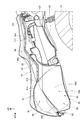
- FIG. 2 is a cross-sectional view of the seat 16, the storage box 44, and the periphery thereof cut vertically in the front-rear direction through the center in the vehicle width direction.
- the sheet 16 wraps the seat base material 81 constituting the skeleton of the seat 16, the cushion member 82 arranged on the upper surface 81a which is the front surface surface of the seat base material 81, and the cushion member 82 from above, and the peripheral portion thereof is a seat. It is composed of a skin member 83 fixed to the peripheral edge of the base material 81.
- the seat 16 is supported by the front end of the storage box 44 so as to be openable and closable via a hinge 85, and opens or closes the opening 44a provided in the upper part of the storage box 44.
- the storage box 44 is arranged so as to be covered from above by the seat 16, and is arranged above the engine 35 (see FIG. 1) provided in the power unit 14 (see FIG. 1) and the rear end of the main body 44b.
- An extension portion 44c extending rearward from the portion is integrally provided.
- the main body 44b has a large storage unit 44d that can store a large item such as a helmet 88 (see FIG. 3) as a storage item, and a vertically flat small storage unit that is arranged behind the large storage unit 44d and can store small items.
- a unit 44e is provided.
- the small storage portion 44e covers the fuel tank 97 from above.
- the extension portion 44c covers the fuel tank 97 from above, and an accessory storage portion 44f capable of storing tools and the like is provided at the rear portion of the extension portion 44c.
- the sheet 16 includes a seat back storage space 91 formed by an upwardly concave lower surface 81b, which is a surface on the back side of the sheet base material 81.
- the storage box 44 includes a box storage space 92 as a storage space under the seat formed by a portion recessed downward from the entire peripheral edge forming the contour in a plan view.
- the box storage space 92 is arranged below the seat back storage space 91, and the seat back storage space 91 and the box storage space 92 form a spatially continuous storage space 93.
- the seat back storage space 91 and the box storage space 92 may partially overlap.
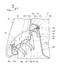
- FIG. 3 is a perspective view showing the lower surface 81b of the sheet base material 81
- FIG. 4 is a cross-sectional view showing a state in which the helmet 88 is stored in the large storage portion 44d of the storage box 44
- FIG. It is an enlarged view which shows.
- the sheet base material 81 extends downward from the upper wall portion 81c constituting the upper portion and the leading edge, left and right side edges, and trailing edge of the upper wall portion 81c and is continuous in the circumferential direction.
- the sheet base material peripheral wall portion 81d formed so as to be provided is integrally provided.
- the sheet base material peripheral wall portion 81d includes a front peripheral wall portion 81e as a peripheral wall portion extending downward from the front edge of the upper wall portion 81c, and a pair of left and right side peripheral wall portions extending downward from the left and right side edges of the upper wall portion 81c, respectively. It includes 81f.
- the front peripheral wall portion 81e is not provided with the cushion member 82 (see FIG. 2), and the skin member 83 (see FIG. 2) is adjacent to the front peripheral wall portion 81e, or the front peripheral wall portion 81e has the upper wall portion 81c and the side portion.
- the cushion member 82 is provided thinner than the peripheral wall portion 81f.
- the large storage portion 44d includes a bottom wall portion 44g as a bottom portion, and a box peripheral wall portion 44h formed so as to be raised from the leading edge, the left and right side edges, and the trailing edge of the bottom wall portion 44g and continuously formed in the circumferential direction. Is provided as one.
- the box peripheral wall portion 44h includes a front peripheral wall portion 44j as a vertical wall raised from the front edge of the bottom wall portion 44g, and a side peripheral wall portion 44k raised from the left and right side edges of the bottom wall portion 44g.
- the box-side hinge portion 44n which is the upper portion of the front surface 44m of the front peripheral wall portion 44j and constitutes the hinge 85 in the vehicle width direction, is integrally formed.
- the helmet 88 can be stored in the large storage unit 44d as a storage item.
- a diffuser 88b is provided at the rear of the helmet 88 to discharge and diffuse the air that has entered the helmet 88 to the outside.
- the helmet 88 is housed in the large storage section 44d with its rear end facing forward, and the diffuser 88b is located above the hinge 85.
- the sheet base material 81 integrally includes a front bottom wall portion 81g as a bottom wall portion extending from the lower portion of the front peripheral wall portion 81e to above the edge portion 44q of the opening 44a of the storage box 44.
- An annular groove 81j that opens downward is formed in the trailing edge portion 81h of the front bottom wall portion 81g, and a sealing member 103 made of an elastic member such as rubber is fitted in the annular groove 81j.
- a seat-side hinge 107 as a hinge member constituting the hinge 85 is screwed to a plurality of bolts 108 provided on the front bottom wall portion 81g and a plurality of bolts 108, respectively. It is attached to the front bottom wall portion 81 g with a plurality of nuts 109.
- the hinge 85 includes the box-side hinge portion 44n, the seat-side hinge 107, and the hinge shaft 101.
- the bolt 108 described above is embedded in a pair of left and right vertical ribs 81 m (see also FIG. 11) protruding into the outer space 94 from the front peripheral wall portion 81e and the front bottom wall portion 81 g.
- the left and right vertical ribs 81m are integrally formed with the front peripheral wall portion 81e and the upper surface 81n of the front bottom wall portion 81g, and extend in the vertical direction.
- the bolt 108 is supported by the front bottom wall portion 81 g and the vertical rib 81 m.
- the box storage space An outer space 94 is formed on the outer side of the vertical plane 105 with respect to 92.
- the outer space 94 is included in the seat back storage space 91. That is, the outer space 94 is formed in front of the front peripheral wall portion 44j (specifically, the inner surface 44r).
- the diffuser 88b of the helmet 88 is arranged in the outer space 94 (specifically, the inter-rib space 95 formed between the left and right vertical ribs 81 m arranged in the outer space 94).
- the helmet 88 can be arranged more forward than when there is no outer space 94 in the seat back storage space 91.
- the storage space 91 on the back of the seat and the storage space 93 can be effectively used, and a large number of stored items can be stored in the storage space 93.
- FIG. 6 is an enlarged view showing a main part of FIG. 2, and is a view showing the rear part of the seat 16 and the storage box 44 shown in FIG. 2 and the periphery of the fuel tank 97.
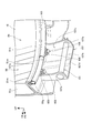
- FIG. 7 is a perspective view showing the storage box 44 and its surroundings
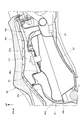
- FIG. 8 is a plan view showing the storage box 44.
- the extension portion 44c has a rear opening 44u formed in the front portion, and a fuel filler port 97a and a fuel filler port provided above the fuel tank 97 from the rear opening 44u.
- the fuel cap 111 that closes 97a is exposed upward.
- the front peripheral wall portion 44j and the left and right side peripheral wall portions 44k of the large storage portion 44d are formed so as to gradually expand to the outside of the storage box 44 from the bottom wall portion 44g upward.
- FIG. 9 is a perspective view showing the hinge 85 and its surroundings
- FIG. 10 is a perspective view for explaining the box-side hinge portion 44n of the storage box 44
- FIG. 11 is a perspective view for explaining the seat-side hinge 107 of the seat 16. be.
- the box-side hinge portion 44n integrally protrudes forward from the front peripheral wall portion 44j of the storage box 44 at a position below the edge portion 44q of the opening 44a of the storage box 44. It is formed like this.
- the box-side hinge portion 44n includes a tubular portion 45f in which a hinge shaft insertion hole 44p is formed, and a plurality of rib portions 45g extending from the upper and lower portions of the tubular portion 45f to the front peripheral wall portion 44j. From the edge portion 44q of the opening portion 44a, an outer peripheral wall portion 45h that gradually extends outward from the box peripheral wall portion 44h as it goes downward is formed, and further, an outer flange portion that extends outward from the lower edge of the outer peripheral wall portion 45h. 45j is formed.
- the outer flange portion 45j includes a notch portion 45k notched at the center in the vehicle width direction, and a box-side hinge portion 44n is provided inside the notch portion 45k in the vehicle width direction.
- the seat-side hinge 107 is formed of a metal plate and includes an upper wall 107a, a front wall 107b, and left and right side walls 107c.
- the upper wall 107a is fastened to the front bottom wall portion 81g with a plurality of bolts 108 and a plurality of nuts 109.
- the front wall 107b is a portion that is bent downward from the front edge of the upper wall 107a, and includes a convex portion 107d for reinforcement that extends vertically in the center in the vehicle width direction and projects rearward.
- a shaft insertion hole 107e through which the hinge shaft 101 is passed is formed in the lower portion of each of the left and right side wall 107c.
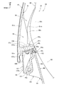
- FIG. 12 is a cross-sectional view showing a hinge 85 when the seat 16 is opened and closed.
- the seat 16 rotates about the hinge shaft 101 of the hinge 85 as shown by the arrow.
- the front peripheral wall portion 81e, the front bottom wall portion 81g, the seat side hinge 107, and the like rotate.
- the seat-side hinge 107 hits the lower end of the stopper portion 45n protruding downward from the tubular portion 45f of the box-side hinge portion 44n, and the rotation is stopped.
- the diffuser 88b as a protruding portion of the helmet 88 arranged in the outer space 94 before opening the seat 16 was closest to the trailing edge portion 81h of the front bottom wall portion 81g. However, by arranging the hinge shaft 101 below the edge portion 44q of the opening 44a, the trailing edge portion 81h is shown by the rotation locus 130 (the portion shown by the broken line). Immediately after opening the seat 16, it descends and separates from the helmet 88, so that it does not interfere with the helmet 88.
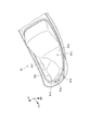
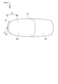
- FIG. 13 is a schematic view showing the positional relationship of the seat back storage space 91, the box storage space 92, and the hinge 85 in a plan view.
- the box storage space 92 is indicated by a solid line
- the outer space 94 of the seat back storage space 91 is indicated by a two-dot chain line drawn in front of the box storage space 92.
- An outer space 94 provided above the hinge 85 is arranged at the front end of the seat back storage space 91.
- the outer space 94 is provided outside the storage box 44 with respect to the box storage space 92, that is, in front of the box storage space 92.
- the motorcycle 10 as a saddle-riding vehicle has a seat back storage space 91 on the back side of the seat 16 and a box storage space below the seat 16 in the vehicle body in a state where the seat 16 is closed.
- a storage space 93 that is spatially continuous with the 92 is provided.
- the seat back storage space 91 includes an outer space 94 located outside the vehicle with respect to the box storage space 92. According to this configuration, the storage space 93 under the seat can be effectively utilized, the storage space 93 can be made larger, and the storage space 93 can be arranged closer to the front of the vehicle.
- the seat 16 is attached to the vehicle body side so as to be openable and closable via the hinge 85, and at least a part of the outer space 94 is provided above the hinge 85.
- the hinge 85 is also arranged on the outer side, it is possible to prevent interference with the storage space when opening and closing the seat. Further, at least the space above the hinge 85 can be effectively utilized.
- the outer space 94 is formed in the front peripheral wall portion 81e provided at the end of the sheet base material 81 provided in the sheet 16 and the upper portion of the box storage space 92 from the lower end of the front peripheral wall portion 81e.
- the front bottom wall portion 81g is formed from the front bottom wall portion 81g extending above the edge portion 44q of the opening 44a, and the front bottom wall portion 81g is provided with a seat side hinge 107 forming a portion of the hinge 85 on the seat 16 side. According to this configuration, it is not necessary to provide the seat base material 81 with a special portion for providing the seat side hinge 107, and the seat base material 81 can be made into a simpler shape.
- the seat side hinge 107 is attached to the lower surface of the front bottom wall portion 81 g by a plurality of bolts 108 and nuts 109, and a plurality of vertical ribs 81 m for supporting the plurality of bolts 108 are provided on the upper surface of the front bottom wall portion 81 g.
- the rib-to-rib space 95 between the plurality of vertical ribs 81 m is located outside the vehicle storage space 92 and forms a part of the outer space 94.
- the front bottom wall portion 81 g can be reinforced by a plurality of vertical ribs 81 m, and the capacity of the box storage space 92 can be secured without the plurality of vertical ribs 81 m narrowing the box storage space 92. ..
- the sheet 16 includes a sheet base material 81 constituting the skeleton of the seat 16 and a skin member 83 provided on the outside of the seat base material 81, and the outer space 94 is provided on the front portion on the back side of the seat 16.
- a cushion member 82 having a cushioning property higher than that of the seat base material 83 is provided between the seat base material 81 and the skin member 83 on the upper portion and the side portion of the seat 16, and a seat is provided on the front portion of the seat 16.
- the skin member 82 is provided directly on the outer surface of the base material 81. According to this configuration, the storage space 93 can be increased and the cushion member 82 can be reduced to reduce the cost without impairing the cushioning property when the occupant sits on the seat 16.
- the diffuser 88b provided in the helmet 88 can be stored in the rib space 95 between the plurality of vertical ribs 81 m. According to this configuration, when the helmet 88 is stored, the diffuser 88b of the helmet 88 can be stored more outside the vehicle, so that the storage space 93 under the seat can be effectively utilized, thereby increasing the amount. A space for storing stored items can be secured.
- the box storage space 92 is formed in the storage box 44 arranged on the vehicle body side, and the hinge shaft 101 of the hinge 85 is an opening 44a provided in the upper part of the storage box 44. It is arranged below the edge 44q of the. According to this configuration, when the sheet 16 is opened, it is possible to prevent a part of the sheet 16 from interfering with the stored items in the outer space 94.
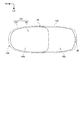
- FIG. 14 is a schematic view showing the outer space 134 of the second embodiment of the present invention.
- a seat 136 is supported on the rear end of the storage box 44 via a hinge 85 so as to be openable and closable.
- the sheet 136 includes a seat back storage space 131 formed by a concave lower surface which is a back surface of the sheet base material.
- the seat back storage space 131 is indicated by a two-dot chain line drawn around the box storage space 92.
- the seat back storage space 131 includes an outer space 134 that bulges forward, left and right sides, and rearward with respect to the box storage space 92.
- the seat back storage space 131 and the box storage space 92 constitute a storage space 133.
- the outer space 134 may be provided so as to bulge only to the left and right sides, only to the left or right side, only to the rear, or only to the front and the rear with respect to the box storage space 92.
- the position of the hinge 85 may be set so that the outer space 134 is arranged above the hinge 85.
- the above-described embodiment shows only one aspect of the present invention, and can be arbitrarily modified and applied without departing from the gist of the present invention.
- the outer spaces 94 and 134 are provided above the hinge 85, but the present invention is not limited to this, and the outer spaces 94 and 134 may be provided in the seat back storage spaces 91 and 131 other than above the hinge 85.
- the present invention is not limited to the case where it is applied to the motorcycle 10, and can be applied to a saddle-riding vehicle including other than the motorcycle 10.
Landscapes
- Engineering & Computer Science (AREA)
- Mechanical Engineering (AREA)
- Automatic Cycles, And Cycles In General (AREA)
Priority Applications (1)
| Application Number | Priority Date | Filing Date | Title |
|---|---|---|---|
| JP2022511571A JP7367184B2 (ja) | 2020-03-31 | 2021-01-25 | 鞍乗り型車両 |
Applications Claiming Priority (2)
| Application Number | Priority Date | Filing Date | Title |
|---|---|---|---|
| JP2020-062624 | 2020-03-31 | ||
| JP2020062624 | 2020-03-31 |
Publications (1)
| Publication Number | Publication Date |
|---|---|
| WO2021199615A1 true WO2021199615A1 (ja) | 2021-10-07 |
Family
ID=77929064
Family Applications (1)
| Application Number | Title | Priority Date | Filing Date |
|---|---|---|---|
| PCT/JP2021/002488 Ceased WO2021199615A1 (ja) | 2020-03-31 | 2021-01-25 | 鞍乗り型車両 |
Country Status (2)
| Country | Link |
|---|---|
| JP (1) | JP7367184B2 (https=) |
| WO (1) | WO2021199615A1 (https=) |
Cited By (1)
| Publication number | Priority date | Publication date | Assignee | Title |
|---|---|---|---|---|
| EP4212419A1 (en) * | 2022-01-13 | 2023-07-19 | Yamaha Hatsudoki Kabushiki Kaisha | Straddled vehicle |
Citations (6)
| Publication number | Priority date | Publication date | Assignee | Title |
|---|---|---|---|---|
| JP2008056009A (ja) * | 2006-08-30 | 2008-03-13 | Honda Motor Co Ltd | 自動二輪車のシート構造 |
| JP2012116361A (ja) * | 2010-12-01 | 2012-06-21 | Honda Motor Co Ltd | 鞍乗り型車両のシート |
| JP2012214064A (ja) * | 2011-03-31 | 2012-11-08 | Honda Motor Co Ltd | 鞍乗型車両のシート構造 |
| JP2013199205A (ja) * | 2012-03-26 | 2013-10-03 | Honda Motor Co Ltd | スクータ型自動二輪車 |
| JP2014043191A (ja) * | 2012-08-28 | 2014-03-13 | Honda Motor Co Ltd | 鞍乗り型車両の配索構造 |
| JP2014213816A (ja) * | 2013-04-30 | 2014-11-17 | スズキ株式会社 | 二輪車の荷物収納構造 |
-
2021
- 2021-01-25 WO PCT/JP2021/002488 patent/WO2021199615A1/ja not_active Ceased
- 2021-01-25 JP JP2022511571A patent/JP7367184B2/ja active Active
Patent Citations (6)
| Publication number | Priority date | Publication date | Assignee | Title |
|---|---|---|---|---|
| JP2008056009A (ja) * | 2006-08-30 | 2008-03-13 | Honda Motor Co Ltd | 自動二輪車のシート構造 |
| JP2012116361A (ja) * | 2010-12-01 | 2012-06-21 | Honda Motor Co Ltd | 鞍乗り型車両のシート |
| JP2012214064A (ja) * | 2011-03-31 | 2012-11-08 | Honda Motor Co Ltd | 鞍乗型車両のシート構造 |
| JP2013199205A (ja) * | 2012-03-26 | 2013-10-03 | Honda Motor Co Ltd | スクータ型自動二輪車 |
| JP2014043191A (ja) * | 2012-08-28 | 2014-03-13 | Honda Motor Co Ltd | 鞍乗り型車両の配索構造 |
| JP2014213816A (ja) * | 2013-04-30 | 2014-11-17 | スズキ株式会社 | 二輪車の荷物収納構造 |
Cited By (1)
| Publication number | Priority date | Publication date | Assignee | Title |
|---|---|---|---|---|
| EP4212419A1 (en) * | 2022-01-13 | 2023-07-19 | Yamaha Hatsudoki Kabushiki Kaisha | Straddled vehicle |
Also Published As
| Publication number | Publication date |
|---|---|
| JP7367184B2 (ja) | 2023-10-23 |
| JPWO2021199615A1 (https=) | 2021-10-07 |
Similar Documents
| Publication | Publication Date | Title |
|---|---|---|
| JP2918116B2 (ja) | スクータ型自動二,三輪車の燃料供給部構造 | |
| US8727058B2 (en) | Saddle type vehicle | |
| JP3879437B2 (ja) | 自動二輪車の物品収納装置 | |
| JP5738163B2 (ja) | 車体構造 | |
| JP5078469B2 (ja) | 鞍乗り型車両 | |
| JP7367184B2 (ja) | 鞍乗り型車両 | |
| JP6902380B2 (ja) | 鞍乗り型車両のシートキャッチ取付構造 | |
| JP5560059B2 (ja) | 鞍乗り型車両 | |
| JP5588701B2 (ja) | 鞍乗り型車両のカバー構造 | |
| US10266047B2 (en) | Valve protection structure for vehicle | |
| JP5869889B2 (ja) | 鞍乗型車両 | |
| JP7015464B2 (ja) | 車両の収納ボックス | |
| JPS633915Y2 (https=) | ||
| JP4726558B2 (ja) | 自動二輪車の燃料タンク取付構造 | |
| JP6982184B2 (ja) | 鞍乗型車両 | |
| JP4571033B2 (ja) | 車両の燃料タンク配置構造 | |
| JPH09301247A (ja) | スクータ型車両におけるリヤカバー取付構造 | |
| JP2006315503A5 (https=) | ||
| JP2006315503A (ja) | 自動二輪車の燃料タンク及び収納ボックスの配置構造 | |
| JP5681620B2 (ja) | 自動二輪車用フィラキャップの拘束構造 | |
| EP4420965B1 (en) | Straddled vehicle | |
| JP6855517B2 (ja) | 鞍乗型車両の給油口構造 | |
| JP2552222B2 (ja) | スクータ型車両のヘルメット収納箱装置 | |
| JP7214683B2 (ja) | 鞍乗り型車両 | |
| JP2700467B2 (ja) | スクータ型車両 |
Legal Events
| Date | Code | Title | Description |
|---|---|---|---|
| 121 | Ep: the epo has been informed by wipo that ep was designated in this application |
Ref document number: 21779147 Country of ref document: EP Kind code of ref document: A1 |
|
| ENP | Entry into the national phase |
Ref document number: 2022511571 Country of ref document: JP Kind code of ref document: A |
|
| WWE | Wipo information: entry into national phase |
Ref document number: 202217059861 Country of ref document: IN |
|
| NENP | Non-entry into the national phase |
Ref country code: DE |
|
| 122 | Ep: pct application non-entry in european phase |
Ref document number: 21779147 Country of ref document: EP Kind code of ref document: A1 |