WO2021199615A1 - Saddle-type vehicle - Google Patents
Saddle-type vehicle Download PDFInfo
- Publication number
- WO2021199615A1 WO2021199615A1 PCT/JP2021/002488 JP2021002488W WO2021199615A1 WO 2021199615 A1 WO2021199615 A1 WO 2021199615A1 JP 2021002488 W JP2021002488 W JP 2021002488W WO 2021199615 A1 WO2021199615 A1 WO 2021199615A1
- Authority
- WO
- WIPO (PCT)
- Prior art keywords
- seat
- storage space
- space
- hinge
- wall portion
- Prior art date
Links
Images


Classifications
-
- B—PERFORMING OPERATIONS; TRANSPORTING
- B62—LAND VEHICLES FOR TRAVELLING OTHERWISE THAN ON RAILS
- B62J—CYCLE SADDLES OR SEATS; AUXILIARY DEVICES OR ACCESSORIES SPECIALLY ADAPTED TO CYCLES AND NOT OTHERWISE PROVIDED FOR, e.g. ARTICLE CARRIERS OR CYCLE PROTECTORS
- B62J1/00—Saddles or other seats for cycles; Arrangement thereof; Component parts
- B62J1/12—Box-shaped seats; Bench-type seats, e.g. dual or twin seats
-
- B—PERFORMING OPERATIONS; TRANSPORTING
- B62—LAND VEHICLES FOR TRAVELLING OTHERWISE THAN ON RAILS
- B62J—CYCLE SADDLES OR SEATS; AUXILIARY DEVICES OR ACCESSORIES SPECIALLY ADAPTED TO CYCLES AND NOT OTHERWISE PROVIDED FOR, e.g. ARTICLE CARRIERS OR CYCLE PROTECTORS
- B62J9/00—Containers specially adapted for cycles, e.g. panniers or saddle bags
- B62J9/10—Containers specially adapted for cycles, e.g. panniers or saddle bags integrated with the cycle
- B62J9/14—Containers specially adapted for cycles, e.g. panniers or saddle bags integrated with the cycle under the saddle
Definitions
- the present invention relates to a saddle-riding vehicle.
- a storage box is arranged under the seat, and a storage space is formed by the space behind the seat and the storage box (see, for example, Patent Document 1).
- An object of the present invention is to provide a saddle-riding vehicle capable of effectively utilizing the storage space under the seat, increasing the storage space, and arranging the storage space closer to the front of the vehicle.
- the seats (16,136) are attached to the vehicle body side so as to be openable and closable via a hinge (85), and the outer space (94,134) is at least partially above the hinge (85). It may be provided in.
- the outer space (94, 134) is a peripheral wall portion (81e) provided at the end portion of the sheet base material (81) provided in the sheet (16, 136) and the peripheral wall portion (81e). It is formed from a bottom wall portion (81 g) extending from the lower end to above the edge portion (44q) of the opening (44a) provided in the upper part of the storage space under the seat (92), and is formed on the bottom wall portion (81 g).
- the hinge member (107) constituting the hinge (85) may be provided.
- the hinge member (107) is attached to the lower surface of the bottom wall portion (81 g) by a plurality of fastening members (108, 109), and the plurality of said members are attached to the upper surface of the bottom wall portion (81 g).
- a plurality of ribs (81 m) for supporting the fastening member (108) are provided, and the space (95) between the plurality of ribs (81 m) is located outside the vehicle with respect to the storage space under the seat (92).
- a part of the outer space (94,134) may be formed.
- the sheet (16, 136) is a sheet base material (81) constituting the skeleton of the sheet (16, 136) and a skin member provided on the outside of the sheet base material (81).
- the outer space (94,134) is provided in the front portion on the back side of the sheet (16, 136), and the upper portion and the side portion of the sheet (16, 136) are provided with the sheet.
- a cushion member (82) having a cushioning property higher than that of the seat base material (83) is provided between the base material (81) and the skin member (83), and the front portion of the seat (16, 136) is provided with a cushion member (82).
- the skin member (82) may be provided directly on the outer surface of the sheet base material (81).
- the outer space (94,134) includes a plurality of diffusers (88b) provided in the helmet (88) when the helmet (88) is stored in the storage space (93,133). It may be stored in the space (95) between the ribs (81 m).
- the storage space under the seat (92) is formed in the storage box (44) arranged on the vehicle body side, and the hinge shaft (101) of the hinge (85) is the storage box (44). ) May be placed below the edge (44q) of the opening (44a) provided above.
- the storage space behind the seat is provided with an outer space located outside the vehicle than the storage space under the seat.
- the storage space can be arranged closer to the front of the vehicle.
- the seat is attached to the vehicle body side via a hinge so as to be openable and closable, and at least a part of the outer space is provided above the hinge. Occasionally, interference with the storage space can be prevented or suppressed. In addition, at least the space above the hinge can be effectively used.
- the outer space extends from the peripheral wall portion provided at the end of the sheet base material provided in the seat and the lower end of the peripheral wall portion to above the edge portion of the opening provided in the upper part of the storage space under the seat. Since the hinge member formed from the bottom wall portion and forming the hinge is provided on the bottom wall portion, it is not necessary to provide a special part for providing the hinge member on the seat base material, and the seat base material has a simpler shape. can.
- the hinge member is attached to the lower surface of the bottom wall portion by a plurality of fastening members, and a plurality of ribs for supporting the fastening member are provided on the upper surface of the bottom wall portion, and the space between the plurality of ribs is provided. Since it is located on the outside of the vehicle from the storage space under the seat and forms a part of the outside space, the bottom wall can be reinforced with multiple ribs, and the multiple ribs do not narrow the storage space, so the storage space can be used. Capacity can be secured.
- the seat includes a sheet base material constituting the skeleton of the seat and a skin member provided on the outside of the seat base material, and an outer space is provided on the front portion on the back side of the seat.
- the upper part and the side part of the seat are provided with a cushion member having a higher cushioning property than the seat base material between the seat base material and the skin member, and the front part of the seat is directly on the outer surface of the seat base material. Since the skin member is provided, the storage space can be increased and the cushion member can be reduced to reduce the cost without impairing the cushioning property when the occupant sits on the seat.
- the diffuser provided in the helmet can be stored in the space between the plurality of ribs in the outer space. Since it can be stored on the outside of the vehicle, the storage space under the seat can be effectively used, and as a result, a space for storing more stored items can be secured.
- the storage space under the seat is formed in the storage box arranged on the vehicle body side, and the hinge shaft of the hinge is arranged below the edge of the opening provided in the upper part of the storage box. Therefore, when the sheet is opened, it is possible to prevent a part of the sheet from interfering with the stored items in the outer space.
- FIG. 1 is a left side view showing a motorcycle according to a first embodiment of the present invention.
- FIG. 2 is a cross-sectional view of the storage box and its periphery cut vertically in the front-rear direction through the center in the vehicle width direction.
- FIG. 3 is a perspective view showing the lower surface of the sheet base material.
- FIG. 4 is a cross-sectional view showing a state in which the helmet is stored in the large storage portion of the storage box.
- FIG. 5 is an enlarged view showing a main part of FIG.
- FIG. 6 is an enlarged view showing a main part of FIG.
- FIG. 7 is a perspective view showing the storage box and its surroundings.
- FIG. 8 is a plan view showing the storage box.
- FIG. 9 is a perspective view showing the hinge and its surroundings.
- FIG. 10 is a perspective view illustrating a box-side hinge portion of the storage box.
- FIG. 11 is a perspective view illustrating the seat side hinge of the seat.
- FIG. 12 is a cross-sectional view showing a hinge when the seat is opened and closed.
- FIG. 13 is a schematic view showing the positional relationship between the seat back storage space, the box storage space, and the hinge in a plan view.
- FIG. 14 is a schematic view showing the outer space of the second embodiment of the present invention.
- FIG. 1 is a left side view showing a motorcycle 10 according to a first embodiment of the present invention.
- the front wheels 13 are supported at the front end of the body frame 11 via the front fork 12, and the rear wheels 15 are supported at the lower part of the body frame 11 via the power unit 14.
- the motorcycle 10 is a saddle-riding vehicle that rides on a seat 16 arranged above the body frame 11.
- the body frame 11 includes a head pipe 18, a pair of left and right down frames 19A, a pair of left and right lower frames 19B, a center frame 20, a pair of left and right rear frames 21, and a pair of left and right floor frames 22.
- the seat 16 includes a front seat 16a on which the driver sits and a rear seat 16b on which the passenger sits.
- storage boxes 44 supported by the left and right rear frames 21 are arranged below the storage box 44.
- a fuel tank 97 supported by the vehicle body frame 11 is arranged below and behind the storage box 44.
- An opening 44a (see FIG. 2) is provided at the upper end of the storage box 44, and the opening 44a is opened or closed by a seat 16 swingably attached to the front end of the storage box 44.
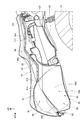
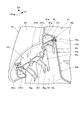
- FIG. 2 is a cross-sectional view of the seat 16, the storage box 44, and the periphery thereof cut vertically in the front-rear direction through the center in the vehicle width direction.
- the sheet 16 wraps the seat base material 81 constituting the skeleton of the seat 16, the cushion member 82 arranged on the upper surface 81a which is the front surface surface of the seat base material 81, and the cushion member 82 from above, and the peripheral portion thereof is a seat. It is composed of a skin member 83 fixed to the peripheral edge of the base material 81.
- the seat 16 is supported by the front end of the storage box 44 so as to be openable and closable via a hinge 85, and opens or closes the opening 44a provided in the upper part of the storage box 44.
- the storage box 44 is arranged so as to be covered from above by the seat 16, and is arranged above the engine 35 (see FIG. 1) provided in the power unit 14 (see FIG. 1) and the rear end of the main body 44b.
- An extension portion 44c extending rearward from the portion is integrally provided.
- the main body 44b has a large storage unit 44d that can store a large item such as a helmet 88 (see FIG. 3) as a storage item, and a vertically flat small storage unit that is arranged behind the large storage unit 44d and can store small items.
- a unit 44e is provided.
- the small storage portion 44e covers the fuel tank 97 from above.
- the extension portion 44c covers the fuel tank 97 from above, and an accessory storage portion 44f capable of storing tools and the like is provided at the rear portion of the extension portion 44c.
- the sheet 16 includes a seat back storage space 91 formed by an upwardly concave lower surface 81b, which is a surface on the back side of the sheet base material 81.
- the storage box 44 includes a box storage space 92 as a storage space under the seat formed by a portion recessed downward from the entire peripheral edge forming the contour in a plan view.
- the box storage space 92 is arranged below the seat back storage space 91, and the seat back storage space 91 and the box storage space 92 form a spatially continuous storage space 93.
- the seat back storage space 91 and the box storage space 92 may partially overlap.
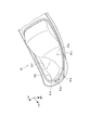
- FIG. 3 is a perspective view showing the lower surface 81b of the sheet base material 81
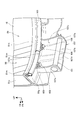
- FIG. 4 is a cross-sectional view showing a state in which the helmet 88 is stored in the large storage portion 44d of the storage box 44
- FIG. It is an enlarged view which shows.
- the sheet base material 81 extends downward from the upper wall portion 81c constituting the upper portion and the leading edge, left and right side edges, and trailing edge of the upper wall portion 81c and is continuous in the circumferential direction.
- the sheet base material peripheral wall portion 81d formed so as to be provided is integrally provided.
- the sheet base material peripheral wall portion 81d includes a front peripheral wall portion 81e as a peripheral wall portion extending downward from the front edge of the upper wall portion 81c, and a pair of left and right side peripheral wall portions extending downward from the left and right side edges of the upper wall portion 81c, respectively. It includes 81f.
- the front peripheral wall portion 81e is not provided with the cushion member 82 (see FIG. 2), and the skin member 83 (see FIG. 2) is adjacent to the front peripheral wall portion 81e, or the front peripheral wall portion 81e has the upper wall portion 81c and the side portion.
- the cushion member 82 is provided thinner than the peripheral wall portion 81f.
- the large storage portion 44d includes a bottom wall portion 44g as a bottom portion, and a box peripheral wall portion 44h formed so as to be raised from the leading edge, the left and right side edges, and the trailing edge of the bottom wall portion 44g and continuously formed in the circumferential direction. Is provided as one.
- the box peripheral wall portion 44h includes a front peripheral wall portion 44j as a vertical wall raised from the front edge of the bottom wall portion 44g, and a side peripheral wall portion 44k raised from the left and right side edges of the bottom wall portion 44g.
- the box-side hinge portion 44n which is the upper portion of the front surface 44m of the front peripheral wall portion 44j and constitutes the hinge 85 in the vehicle width direction, is integrally formed.
- the helmet 88 can be stored in the large storage unit 44d as a storage item.
- a diffuser 88b is provided at the rear of the helmet 88 to discharge and diffuse the air that has entered the helmet 88 to the outside.
- the helmet 88 is housed in the large storage section 44d with its rear end facing forward, and the diffuser 88b is located above the hinge 85.
- the sheet base material 81 integrally includes a front bottom wall portion 81g as a bottom wall portion extending from the lower portion of the front peripheral wall portion 81e to above the edge portion 44q of the opening 44a of the storage box 44.
- An annular groove 81j that opens downward is formed in the trailing edge portion 81h of the front bottom wall portion 81g, and a sealing member 103 made of an elastic member such as rubber is fitted in the annular groove 81j.
- a seat-side hinge 107 as a hinge member constituting the hinge 85 is screwed to a plurality of bolts 108 provided on the front bottom wall portion 81g and a plurality of bolts 108, respectively. It is attached to the front bottom wall portion 81 g with a plurality of nuts 109.
- the hinge 85 includes the box-side hinge portion 44n, the seat-side hinge 107, and the hinge shaft 101.
- the bolt 108 described above is embedded in a pair of left and right vertical ribs 81 m (see also FIG. 11) protruding into the outer space 94 from the front peripheral wall portion 81e and the front bottom wall portion 81 g.
- the left and right vertical ribs 81m are integrally formed with the front peripheral wall portion 81e and the upper surface 81n of the front bottom wall portion 81g, and extend in the vertical direction.
- the bolt 108 is supported by the front bottom wall portion 81 g and the vertical rib 81 m.
- the box storage space An outer space 94 is formed on the outer side of the vertical plane 105 with respect to 92.
- the outer space 94 is included in the seat back storage space 91. That is, the outer space 94 is formed in front of the front peripheral wall portion 44j (specifically, the inner surface 44r).
- the diffuser 88b of the helmet 88 is arranged in the outer space 94 (specifically, the inter-rib space 95 formed between the left and right vertical ribs 81 m arranged in the outer space 94).
- the helmet 88 can be arranged more forward than when there is no outer space 94 in the seat back storage space 91.
- the storage space 91 on the back of the seat and the storage space 93 can be effectively used, and a large number of stored items can be stored in the storage space 93.
- FIG. 6 is an enlarged view showing a main part of FIG. 2, and is a view showing the rear part of the seat 16 and the storage box 44 shown in FIG. 2 and the periphery of the fuel tank 97.
- FIG. 7 is a perspective view showing the storage box 44 and its surroundings
- FIG. 8 is a plan view showing the storage box 44.
- the extension portion 44c has a rear opening 44u formed in the front portion, and a fuel filler port 97a and a fuel filler port provided above the fuel tank 97 from the rear opening 44u.
- the fuel cap 111 that closes 97a is exposed upward.
- the front peripheral wall portion 44j and the left and right side peripheral wall portions 44k of the large storage portion 44d are formed so as to gradually expand to the outside of the storage box 44 from the bottom wall portion 44g upward.
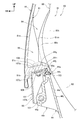
- FIG. 9 is a perspective view showing the hinge 85 and its surroundings
- FIG. 10 is a perspective view for explaining the box-side hinge portion 44n of the storage box 44
- FIG. 11 is a perspective view for explaining the seat-side hinge 107 of the seat 16. be.
- the box-side hinge portion 44n integrally protrudes forward from the front peripheral wall portion 44j of the storage box 44 at a position below the edge portion 44q of the opening 44a of the storage box 44. It is formed like this.
- the box-side hinge portion 44n includes a tubular portion 45f in which a hinge shaft insertion hole 44p is formed, and a plurality of rib portions 45g extending from the upper and lower portions of the tubular portion 45f to the front peripheral wall portion 44j. From the edge portion 44q of the opening portion 44a, an outer peripheral wall portion 45h that gradually extends outward from the box peripheral wall portion 44h as it goes downward is formed, and further, an outer flange portion that extends outward from the lower edge of the outer peripheral wall portion 45h. 45j is formed.
- the outer flange portion 45j includes a notch portion 45k notched at the center in the vehicle width direction, and a box-side hinge portion 44n is provided inside the notch portion 45k in the vehicle width direction.
- the seat-side hinge 107 is formed of a metal plate and includes an upper wall 107a, a front wall 107b, and left and right side walls 107c.
- the upper wall 107a is fastened to the front bottom wall portion 81g with a plurality of bolts 108 and a plurality of nuts 109.
- the front wall 107b is a portion that is bent downward from the front edge of the upper wall 107a, and includes a convex portion 107d for reinforcement that extends vertically in the center in the vehicle width direction and projects rearward.
- a shaft insertion hole 107e through which the hinge shaft 101 is passed is formed in the lower portion of each of the left and right side wall 107c.
- FIG. 12 is a cross-sectional view showing a hinge 85 when the seat 16 is opened and closed.
- the seat 16 rotates about the hinge shaft 101 of the hinge 85 as shown by the arrow.
- the front peripheral wall portion 81e, the front bottom wall portion 81g, the seat side hinge 107, and the like rotate.
- the seat-side hinge 107 hits the lower end of the stopper portion 45n protruding downward from the tubular portion 45f of the box-side hinge portion 44n, and the rotation is stopped.
- the diffuser 88b as a protruding portion of the helmet 88 arranged in the outer space 94 before opening the seat 16 was closest to the trailing edge portion 81h of the front bottom wall portion 81g. However, by arranging the hinge shaft 101 below the edge portion 44q of the opening 44a, the trailing edge portion 81h is shown by the rotation locus 130 (the portion shown by the broken line). Immediately after opening the seat 16, it descends and separates from the helmet 88, so that it does not interfere with the helmet 88.
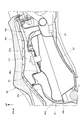
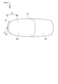
- FIG. 13 is a schematic view showing the positional relationship of the seat back storage space 91, the box storage space 92, and the hinge 85 in a plan view.
- the box storage space 92 is indicated by a solid line
- the outer space 94 of the seat back storage space 91 is indicated by a two-dot chain line drawn in front of the box storage space 92.
- An outer space 94 provided above the hinge 85 is arranged at the front end of the seat back storage space 91.
- the outer space 94 is provided outside the storage box 44 with respect to the box storage space 92, that is, in front of the box storage space 92.
- the motorcycle 10 as a saddle-riding vehicle has a seat back storage space 91 on the back side of the seat 16 and a box storage space below the seat 16 in the vehicle body in a state where the seat 16 is closed.
- a storage space 93 that is spatially continuous with the 92 is provided.
- the seat back storage space 91 includes an outer space 94 located outside the vehicle with respect to the box storage space 92. According to this configuration, the storage space 93 under the seat can be effectively utilized, the storage space 93 can be made larger, and the storage space 93 can be arranged closer to the front of the vehicle.
- the seat 16 is attached to the vehicle body side so as to be openable and closable via the hinge 85, and at least a part of the outer space 94 is provided above the hinge 85.
- the hinge 85 is also arranged on the outer side, it is possible to prevent interference with the storage space when opening and closing the seat. Further, at least the space above the hinge 85 can be effectively utilized.
- the outer space 94 is formed in the front peripheral wall portion 81e provided at the end of the sheet base material 81 provided in the sheet 16 and the upper portion of the box storage space 92 from the lower end of the front peripheral wall portion 81e.
- the front bottom wall portion 81g is formed from the front bottom wall portion 81g extending above the edge portion 44q of the opening 44a, and the front bottom wall portion 81g is provided with a seat side hinge 107 forming a portion of the hinge 85 on the seat 16 side. According to this configuration, it is not necessary to provide the seat base material 81 with a special portion for providing the seat side hinge 107, and the seat base material 81 can be made into a simpler shape.
- the seat side hinge 107 is attached to the lower surface of the front bottom wall portion 81 g by a plurality of bolts 108 and nuts 109, and a plurality of vertical ribs 81 m for supporting the plurality of bolts 108 are provided on the upper surface of the front bottom wall portion 81 g.
- the rib-to-rib space 95 between the plurality of vertical ribs 81 m is located outside the vehicle storage space 92 and forms a part of the outer space 94.
- the front bottom wall portion 81 g can be reinforced by a plurality of vertical ribs 81 m, and the capacity of the box storage space 92 can be secured without the plurality of vertical ribs 81 m narrowing the box storage space 92. ..
- the sheet 16 includes a sheet base material 81 constituting the skeleton of the seat 16 and a skin member 83 provided on the outside of the seat base material 81, and the outer space 94 is provided on the front portion on the back side of the seat 16.
- a cushion member 82 having a cushioning property higher than that of the seat base material 83 is provided between the seat base material 81 and the skin member 83 on the upper portion and the side portion of the seat 16, and a seat is provided on the front portion of the seat 16.
- the skin member 82 is provided directly on the outer surface of the base material 81. According to this configuration, the storage space 93 can be increased and the cushion member 82 can be reduced to reduce the cost without impairing the cushioning property when the occupant sits on the seat 16.
- the diffuser 88b provided in the helmet 88 can be stored in the rib space 95 between the plurality of vertical ribs 81 m. According to this configuration, when the helmet 88 is stored, the diffuser 88b of the helmet 88 can be stored more outside the vehicle, so that the storage space 93 under the seat can be effectively utilized, thereby increasing the amount. A space for storing stored items can be secured.
- the box storage space 92 is formed in the storage box 44 arranged on the vehicle body side, and the hinge shaft 101 of the hinge 85 is an opening 44a provided in the upper part of the storage box 44. It is arranged below the edge 44q of the. According to this configuration, when the sheet 16 is opened, it is possible to prevent a part of the sheet 16 from interfering with the stored items in the outer space 94.
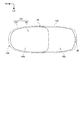
- FIG. 14 is a schematic view showing the outer space 134 of the second embodiment of the present invention.
- a seat 136 is supported on the rear end of the storage box 44 via a hinge 85 so as to be openable and closable.
- the sheet 136 includes a seat back storage space 131 formed by a concave lower surface which is a back surface of the sheet base material.
- the seat back storage space 131 is indicated by a two-dot chain line drawn around the box storage space 92.
- the seat back storage space 131 includes an outer space 134 that bulges forward, left and right sides, and rearward with respect to the box storage space 92.
- the seat back storage space 131 and the box storage space 92 constitute a storage space 133.
- the outer space 134 may be provided so as to bulge only to the left and right sides, only to the left or right side, only to the rear, or only to the front and the rear with respect to the box storage space 92.
- the position of the hinge 85 may be set so that the outer space 134 is arranged above the hinge 85.
- the above-described embodiment shows only one aspect of the present invention, and can be arbitrarily modified and applied without departing from the gist of the present invention.
- the outer spaces 94 and 134 are provided above the hinge 85, but the present invention is not limited to this, and the outer spaces 94 and 134 may be provided in the seat back storage spaces 91 and 131 other than above the hinge 85.
- the present invention is not limited to the case where it is applied to the motorcycle 10, and can be applied to a saddle-riding vehicle including other than the motorcycle 10.
Abstract
Provided is a saddle-type vehicle in which it is possible to further increase storage space by efficiently utilizing the storage space under a seat and to provide the storage space on the front side of the vehicle. A motorcycle according to the present invention includes a storage space 93 in which a seat-back storage space 91 on the back of a seat 16 and a box storage space 92 located below the seat 16 in a vehicle body are spatially continuous with each other in a state in which the seat 16 is closed. The seat-back storage space 91 includes an outside space 94 that is located on the side of the vehicle farther outward than the box storage space 92 is in a state in which the seat 16 is closed.
Description
本発明は、鞍乗り型車両に関する。
The present invention relates to a saddle-riding vehicle.
従来、スクーター型の鞍乗り型車両では、シート下に収納ボックスを配置し、シート裏側の空間と収納ボックスとで収納スペースを形成している(例えば、特許文献1参照)。
Conventionally, in a scooter-type saddle-riding vehicle, a storage box is arranged under the seat, and a storage space is formed by the space behind the seat and the storage box (see, for example, Patent Document 1).
上記した鞍乗り型車両の車両積載性を向上するために、シート下の空間を有効活用して収納スペースをより大きくすることが望まれる。
また、上記した鞍乗り型車両には、収納スペースの後方に燃料タンク等の重量物を配置したものがあり、重量物をできるだけ車両中心に配置するために、収納スペースをより車両前方に配置することが望まれる。
本発明の目的は、シート下の収納スペースを有効活用し、収納スペースをより大きくするとともに、収納スペースを車両前方寄りに配置することが可能な鞍乗り型車両を提供することにある。 In order to improve the vehicle loadability of the saddle-riding vehicle described above, it is desired to effectively utilize the space under the seat to increase the storage space.
In addition, some of the above-mentioned saddle-riding vehicles have heavy objects such as fuel tanks arranged behind the storage space, and the storage space is arranged further in front of the vehicle in order to arrange the heavy objects in the center of the vehicle as much as possible. Is desired.
An object of the present invention is to provide a saddle-riding vehicle capable of effectively utilizing the storage space under the seat, increasing the storage space, and arranging the storage space closer to the front of the vehicle.
この明細書には、2020年3月31日に出願された日本国特許出願・特願2020-062624の全ての内容が含まれる。
鞍乗り型車両は、シート(16,136)を閉じた状態で、前記シート(16,136)の裏側のシート裏収納空間(91,131)と、車体における前記シート(16,136)の下方のシート下収納空間(92)とが空間的に連続する収納スペース(93,133)を備える鞍乗り型車両において、前記シート(16,136)を閉じた状態で、前記シート裏収納空間(91,131)は、前記シート下収納空間(92)よりも車両外側に位置する外側空間(94,134)を備えることを特徴とする。 This specification includes all the contents of the Japanese patent application and Japanese Patent Application No. 2020-62624 filed on March 31, 2020.
In the saddle-riding vehicle, with the seat (16,136) closed, the seat back storage space (91,131) on the back side of the seat (16,136) and the lower part of the seat (16,136) in the vehicle body. In a saddle-riding vehicle having a storage space (93,133) that is spatially continuous with the storage space under the seat (92), the seat back storage space (91) is closed. , 131) is characterized by including an outer space (94, 134) located outside the vehicle with respect to the under-seat storage space (92).
上記構成において、前記シート(16,136)は、ヒンジ(85)を介して車体側に開閉可能に取付けられ、前記外側空間(94,134)は、少なくとも一部が前記ヒンジ(85)の上方に設けられても良い。
In the above configuration, the seats (16,136) are attached to the vehicle body side so as to be openable and closable via a hinge (85), and the outer space (94,134) is at least partially above the hinge (85). It may be provided in.
また、上記構成において、前記外側空間(94,134)は、前記シート(16,136)に備えるシート基材(81)の端部に設けられる周壁部(81e)と、周壁部(81e)の下端から前記シート下収納空間(92)の上部に設けられた開口部(44a)の縁部(44q)の上方まで延びる底壁部(81g)とから形成され、前記底壁部(81g)に、前記ヒンジ(85)を構成するヒンジ部材(107)が設けられても良い。
Further, in the above configuration, the outer space (94, 134) is a peripheral wall portion (81e) provided at the end portion of the sheet base material (81) provided in the sheet (16, 136) and the peripheral wall portion (81e). It is formed from a bottom wall portion (81 g) extending from the lower end to above the edge portion (44q) of the opening (44a) provided in the upper part of the storage space under the seat (92), and is formed on the bottom wall portion (81 g). , The hinge member (107) constituting the hinge (85) may be provided.
また、上記構成において、前記ヒンジ部材(107)は、前記底壁部(81g)の下面に複数の締結部材(108,109)により取付けられ、前記底壁部(81g)の上面に複数の前記締結部材(108)を支持する複数のリブ(81m)が設けられ、複数の前記リブ(81m)の間の空間(95)は、前記シート下収納空間(92)よりも車両外側に位置し、前記外側空間(94,134)の一部を構成しても良い。
Further, in the above configuration, the hinge member (107) is attached to the lower surface of the bottom wall portion (81 g) by a plurality of fastening members (108, 109), and the plurality of said members are attached to the upper surface of the bottom wall portion (81 g). A plurality of ribs (81 m) for supporting the fastening member (108) are provided, and the space (95) between the plurality of ribs (81 m) is located outside the vehicle with respect to the storage space under the seat (92). A part of the outer space (94,134) may be formed.
また、上記構成において、前記シート(16,136)は、前記シート(16,136)の骨格を構成するシート基材(81)と、前記シート基材(81)の外側に設けられた表皮部材(83)とを備え、前記外側空間(94,134)は、前記シート(16,136)の裏側における前部に設けられ、前記シート(16,136)の上部及び側部には、前記シート基材(81)と前記表皮部材(83)との間に前記シート基材(83)よりも高いクッション性を有するクッション部材(82)を備え、前記シート(16,136)の前部には、前記シート基材(81)の外側の面に直接に前記表皮部材(82)が設けられても良い。
Further, in the above configuration, the sheet (16, 136) is a sheet base material (81) constituting the skeleton of the sheet (16, 136) and a skin member provided on the outside of the sheet base material (81). The outer space (94,134) is provided in the front portion on the back side of the sheet (16, 136), and the upper portion and the side portion of the sheet (16, 136) are provided with the sheet. A cushion member (82) having a cushioning property higher than that of the seat base material (83) is provided between the base material (81) and the skin member (83), and the front portion of the seat (16, 136) is provided with a cushion member (82). The skin member (82) may be provided directly on the outer surface of the sheet base material (81).
また、上記構成において、前記外側空間(94,134)は、前記収納スペース(93,133)にヘルメット(88)を収納した場合に、前記ヘルメット(88)に備えるディフューザー(88b)を複数の前記リブ(81m)の間の空間(95)に収納可能であっても良い。
また、上記構成において、前記シート下収納空間(92)は、車体側に配置された収納ボックス(44)内に形成され、前記ヒンジ(85)のヒンジ軸(101)は、前記収納ボックス(44)の上部に設けられた開口部(44a)の縁部(44q)よりも下方に配置されても良い。 Further, in the above configuration, the outer space (94,134) includes a plurality of diffusers (88b) provided in the helmet (88) when the helmet (88) is stored in the storage space (93,133). It may be stored in the space (95) between the ribs (81 m).
Further, in the above configuration, the storage space under the seat (92) is formed in the storage box (44) arranged on the vehicle body side, and the hinge shaft (101) of the hinge (85) is the storage box (44). ) May be placed below the edge (44q) of the opening (44a) provided above.
鞍乗り型車両は、シートを閉じた状態で、シート裏収納空間は、シート下収納空間よりも車両外側に位置する外側空間を備えるので、シート下の収納スペースを有効活用し、収納スペースをより大きくするとともに、収納スペースを車両前方寄りに配置することができる。
In the saddle-riding vehicle, when the seat is closed, the storage space behind the seat is provided with an outer space located outside the vehicle than the storage space under the seat. In addition to being large, the storage space can be arranged closer to the front of the vehicle.
上記構成において、シートは、ヒンジを介して車体側に開閉可能に取付けられ、外側空間は、少なくとも一部がヒンジの上方に設けられるので、ヒンジも、より外側に配置されるため、シートの開閉時に、収納スペースへの干渉を防止又は抑制できる。また、少なくともヒンジの上方のスペースを有効活用できる。
In the above configuration, the seat is attached to the vehicle body side via a hinge so as to be openable and closable, and at least a part of the outer space is provided above the hinge. Occasionally, interference with the storage space can be prevented or suppressed. In addition, at least the space above the hinge can be effectively used.
また、上記構成において、外側空間は、シートに備えるシート基材の端部に設けられる周壁部と、周壁部の下端からシート下収納空間の上部に設けられた開口部の縁部の上方まで延びる底壁部とから形成され、底壁部に、ヒンジを構成するヒンジ部材が設けられるので、特別にヒンジ部材を設ける部位をシート基材に設けなくて済み、シート基材をより単純な形状にできる。
Further, in the above configuration, the outer space extends from the peripheral wall portion provided at the end of the sheet base material provided in the seat and the lower end of the peripheral wall portion to above the edge portion of the opening provided in the upper part of the storage space under the seat. Since the hinge member formed from the bottom wall portion and forming the hinge is provided on the bottom wall portion, it is not necessary to provide a special part for providing the hinge member on the seat base material, and the seat base material has a simpler shape. can.
また、上記構成において、ヒンジ部材は、底壁部の下面に複数の締結部材により取付けられ、底壁部の上面に締結部材を支持する複数のリブが設けられ、複数のリブの間の空間は、シート下収納空間よりも車両外側に位置し、外側空間の一部を構成するので、底壁部を複数のリブで補強できるとともに、複数のリブが収納スペースを狭めることがなく、収納スペースの容量を確保することができる。
Further, in the above configuration, the hinge member is attached to the lower surface of the bottom wall portion by a plurality of fastening members, and a plurality of ribs for supporting the fastening member are provided on the upper surface of the bottom wall portion, and the space between the plurality of ribs is provided. Since it is located on the outside of the vehicle from the storage space under the seat and forms a part of the outside space, the bottom wall can be reinforced with multiple ribs, and the multiple ribs do not narrow the storage space, so the storage space can be used. Capacity can be secured.
また、上記構成において、シートは、シートの骨格を構成するシート基材と、シート基材の外側に設けられた表皮部材とを備え、外側空間は、シートの裏側における前部に設けられ、シートの上部及び側部には、シート基材と表皮部材との間にシート基材よりも高いクッション性を有するクッション部材を備え、シートの前部には、シート基材の外側の面に直接に表皮部材が設けられるので、乗員がシートに着座した際のクッション性を損なうことなしに、収納スペースを大きくできるとともにクッション部材を減らしてコストを削減できる。
Further, in the above configuration, the seat includes a sheet base material constituting the skeleton of the seat and a skin member provided on the outside of the seat base material, and an outer space is provided on the front portion on the back side of the seat. The upper part and the side part of the seat are provided with a cushion member having a higher cushioning property than the seat base material between the seat base material and the skin member, and the front part of the seat is directly on the outer surface of the seat base material. Since the skin member is provided, the storage space can be increased and the cushion member can be reduced to reduce the cost without impairing the cushioning property when the occupant sits on the seat.
また、上記構成において、外側空間は、収納スペースにヘルメットを収納した場合に、ヘルメットに備えるディフューザーを複数のリブの間の空間に収納可能であるので、ヘルメットを収納する場合、ヘルメットのディフューザーをより車両外側に収納することができるため、シート下の収納スペースを有効活用することができ、これによって、より多くの収納物を収納するスペースを確保できる。
Further, in the above configuration, when the helmet is stored in the storage space, the diffuser provided in the helmet can be stored in the space between the plurality of ribs in the outer space. Since it can be stored on the outside of the vehicle, the storage space under the seat can be effectively used, and as a result, a space for storing more stored items can be secured.
また、上記構成において、シート下収納空間は、車体側に配置された収納ボックス内に形成され、ヒンジのヒンジ軸は、収納ボックスの上部に設けられた開口部の縁部よりも下方に配置されるので、シートを開けたときに、シートの一部が外側空間内の収納物に干渉するのを防止できる。
Further, in the above configuration, the storage space under the seat is formed in the storage box arranged on the vehicle body side, and the hinge shaft of the hinge is arranged below the edge of the opening provided in the upper part of the storage box. Therefore, when the sheet is opened, it is possible to prevent a part of the sheet from interfering with the stored items in the outer space.
以下、図面を参照して本発明の各実施形態について説明する。なお、説明中、前後左右及び上下といった方向の記載は、特に記載がなければ車体に対する方向と同一とする。また、各図に示す符号FRは車体前方を示し、符号UPは車体上方を示し、符号LHは車体左方を示している。
<第1実施形態>
図1は、本発明の第1実施形態の自動二輪車10を示す左側面図である。
自動二輪車10は、車体フレーム11の前端部にフロントフォーク12を介して前輪13が支持され、車体フレーム11の下部にパワーユニット14を介して後輪15が支持されている。
自動二輪車10は、車体フレーム11の上方に配置されたシート16に跨って乗車する鞍乗り型車両である。 Hereinafter, embodiments of the present invention will be described with reference to the drawings. In the explanation, the directions such as front / rear / left / right and up / down are the same as the directions with respect to the vehicle body unless otherwise specified. Further, the reference numerals FR shown in each figure indicate the front of the vehicle body, the reference numerals UP indicate the upper part of the vehicle body, and the reference numerals LH indicate the left side of the vehicle body.
<First Embodiment>
FIG. 1 is a left side view showing amotorcycle 10 according to a first embodiment of the present invention.
In themotorcycle 10, the front wheels 13 are supported at the front end of the body frame 11 via the front fork 12, and the rear wheels 15 are supported at the lower part of the body frame 11 via the power unit 14.
Themotorcycle 10 is a saddle-riding vehicle that rides on a seat 16 arranged above the body frame 11.
<第1実施形態>
図1は、本発明の第1実施形態の自動二輪車10を示す左側面図である。
自動二輪車10は、車体フレーム11の前端部にフロントフォーク12を介して前輪13が支持され、車体フレーム11の下部にパワーユニット14を介して後輪15が支持されている。
自動二輪車10は、車体フレーム11の上方に配置されたシート16に跨って乗車する鞍乗り型車両である。 Hereinafter, embodiments of the present invention will be described with reference to the drawings. In the explanation, the directions such as front / rear / left / right and up / down are the same as the directions with respect to the vehicle body unless otherwise specified. Further, the reference numerals FR shown in each figure indicate the front of the vehicle body, the reference numerals UP indicate the upper part of the vehicle body, and the reference numerals LH indicate the left side of the vehicle body.
<First Embodiment>
FIG. 1 is a left side view showing a
In the
The
車体フレーム11は、ヘッドパイプ18、左右一対のダウンフレーム19A、左右一対のロアフレーム19B、センターフレーム20、左右一対のリアフレーム21、左右一対のフロアフレーム22を備える。
The body frame 11 includes a head pipe 18, a pair of left and right down frames 19A, a pair of left and right lower frames 19B, a center frame 20, a pair of left and right rear frames 21, and a pair of left and right floor frames 22.
シート16は、運転者が座る前側シート16aと、同乗者が座る後側シート16bとを備える。シート16の下方には、左右のリアフレーム21に支持された収納ボックス44が配置されている。また、収納ボックス44の下方及び後方には、車体フレーム11に支持された燃料タンク97が配置されている。
収納ボックス44の上端部には開口部44a(図2参照)が設けられ、この開口部44aは、収納ボックス44の前端部に揺動可能に取付けられたシート16によって開放又は閉塞される。 Theseat 16 includes a front seat 16a on which the driver sits and a rear seat 16b on which the passenger sits. Below the seat 16, storage boxes 44 supported by the left and right rear frames 21 are arranged. Further, a fuel tank 97 supported by the vehicle body frame 11 is arranged below and behind the storage box 44.
Anopening 44a (see FIG. 2) is provided at the upper end of the storage box 44, and the opening 44a is opened or closed by a seat 16 swingably attached to the front end of the storage box 44.
収納ボックス44の上端部には開口部44a(図2参照)が設けられ、この開口部44aは、収納ボックス44の前端部に揺動可能に取付けられたシート16によって開放又は閉塞される。 The
An
図2は、シート16、収納ボックス44及びその周囲を車幅方向中央を通って前後方向に縦に切断した断面図である。
シート16は、シート16の骨格を構成するシート基材81と、シート基材81の表側の面である上面81aに配置されたクッション部材82と、クッション部材82を上方から包み込んで周縁部がシート基材81の周縁部に固定された表皮部材83とから構成される。シート16は、収納ボックス44の前端部にヒンジ85を介して開閉可能に支持され、収納ボックス44の上部に設けられた開口部44aを開放又は閉塞する。 FIG. 2 is a cross-sectional view of theseat 16, the storage box 44, and the periphery thereof cut vertically in the front-rear direction through the center in the vehicle width direction.
Thesheet 16 wraps the seat base material 81 constituting the skeleton of the seat 16, the cushion member 82 arranged on the upper surface 81a which is the front surface surface of the seat base material 81, and the cushion member 82 from above, and the peripheral portion thereof is a seat. It is composed of a skin member 83 fixed to the peripheral edge of the base material 81. The seat 16 is supported by the front end of the storage box 44 so as to be openable and closable via a hinge 85, and opens or closes the opening 44a provided in the upper part of the storage box 44.
シート16は、シート16の骨格を構成するシート基材81と、シート基材81の表側の面である上面81aに配置されたクッション部材82と、クッション部材82を上方から包み込んで周縁部がシート基材81の周縁部に固定された表皮部材83とから構成される。シート16は、収納ボックス44の前端部にヒンジ85を介して開閉可能に支持され、収納ボックス44の上部に設けられた開口部44aを開放又は閉塞する。 FIG. 2 is a cross-sectional view of the
The
収納ボックス44は、シート16に上方から覆われるように配置され、パワーユニット14(図1参照)に備えるエンジン35(図1参照)の上方に配置された本体部44bと、本体部44bの後端部から後方に延びる延長部44cとを一体に備える。
本体部44bは、収納物としてのヘルメット88(図3参照)等の大物を収納可能な大収納部44dと、大収納部44dの後方に配置されて小物を収納可能な上下に扁平な小収納部44eとを備える。小収納部44eは、燃料タンク97を上方から覆う。
延長部44cは、燃料タンク97を上方から覆い、延長部44cの後部には、工具等を収納可能な小物収納部44fが設けられている。 Thestorage box 44 is arranged so as to be covered from above by the seat 16, and is arranged above the engine 35 (see FIG. 1) provided in the power unit 14 (see FIG. 1) and the rear end of the main body 44b. An extension portion 44c extending rearward from the portion is integrally provided.
Themain body 44b has a large storage unit 44d that can store a large item such as a helmet 88 (see FIG. 3) as a storage item, and a vertically flat small storage unit that is arranged behind the large storage unit 44d and can store small items. A unit 44e is provided. The small storage portion 44e covers the fuel tank 97 from above.
Theextension portion 44c covers the fuel tank 97 from above, and an accessory storage portion 44f capable of storing tools and the like is provided at the rear portion of the extension portion 44c.
本体部44bは、収納物としてのヘルメット88(図3参照)等の大物を収納可能な大収納部44dと、大収納部44dの後方に配置されて小物を収納可能な上下に扁平な小収納部44eとを備える。小収納部44eは、燃料タンク97を上方から覆う。
延長部44cは、燃料タンク97を上方から覆い、延長部44cの後部には、工具等を収納可能な小物収納部44fが設けられている。 The
The
The
シート16は、シート基材81の裏側の面である上方向に凹形状の下面81bによって出来るシート裏収納空間91を備える。また、収納ボックス44は、その平面視での輪郭を形成する全周縁から下方に凹んだ部分で出来るシート下収納空間としてのボックス収納空間92を備える。
シート16を閉じた状態では、シート裏収納空間91の下方にボックス収納空間92が配置され、シート裏収納空間91とボックス収納空間92とは、空間的に連続する収納スペース93を形成する。シート裏収納空間91とボックス収納空間92とは、部分的に重複しても良い。 Thesheet 16 includes a seat back storage space 91 formed by an upwardly concave lower surface 81b, which is a surface on the back side of the sheet base material 81. Further, the storage box 44 includes a box storage space 92 as a storage space under the seat formed by a portion recessed downward from the entire peripheral edge forming the contour in a plan view.
When theseat 16 is closed, the box storage space 92 is arranged below the seat back storage space 91, and the seat back storage space 91 and the box storage space 92 form a spatially continuous storage space 93. The seat back storage space 91 and the box storage space 92 may partially overlap.
シート16を閉じた状態では、シート裏収納空間91の下方にボックス収納空間92が配置され、シート裏収納空間91とボックス収納空間92とは、空間的に連続する収納スペース93を形成する。シート裏収納空間91とボックス収納空間92とは、部分的に重複しても良い。 The
When the
図3は、シート基材81の下面81bを示す斜視図、図4は、収納ボックス44の大収納部44dにヘルメット88を収納した状態を示す断面図、図5は、図4の要部を示す拡大図である。
図3及び図4に示すように、シート基材81は、上部を構成する上壁部81cと、上壁部81cの前縁、左右の側縁及び後縁から下方に延びて周方向に連続するように形成されたシート基材周壁部81dとを一体に備える。
シート基材周壁部81dは、上壁部81cの前縁から下方に延びる周壁部としての前周壁部81eと、上壁部81cの左右の側縁からそれぞれ下方に延びる左右一対の側部周壁部81fとを備える。前周壁部81eにはクッション部材82(図2参照)が設けられず、前周壁部81eに表皮部材83(図2参照)が隣接する、又は前周壁部81eには上壁部81c及び側部周壁部81fよりもクッション部材82が薄く設けられる。 FIG. 3 is a perspective view showing thelower surface 81b of the sheet base material 81, FIG. 4 is a cross-sectional view showing a state in which the helmet 88 is stored in the large storage portion 44d of the storage box 44, and FIG. It is an enlarged view which shows.
As shown in FIGS. 3 and 4, thesheet base material 81 extends downward from the upper wall portion 81c constituting the upper portion and the leading edge, left and right side edges, and trailing edge of the upper wall portion 81c and is continuous in the circumferential direction. The sheet base material peripheral wall portion 81d formed so as to be provided is integrally provided.
The sheet base materialperipheral wall portion 81d includes a front peripheral wall portion 81e as a peripheral wall portion extending downward from the front edge of the upper wall portion 81c, and a pair of left and right side peripheral wall portions extending downward from the left and right side edges of the upper wall portion 81c, respectively. It includes 81f. The front peripheral wall portion 81e is not provided with the cushion member 82 (see FIG. 2), and the skin member 83 (see FIG. 2) is adjacent to the front peripheral wall portion 81e, or the front peripheral wall portion 81e has the upper wall portion 81c and the side portion. The cushion member 82 is provided thinner than the peripheral wall portion 81f.
図3及び図4に示すように、シート基材81は、上部を構成する上壁部81cと、上壁部81cの前縁、左右の側縁及び後縁から下方に延びて周方向に連続するように形成されたシート基材周壁部81dとを一体に備える。
シート基材周壁部81dは、上壁部81cの前縁から下方に延びる周壁部としての前周壁部81eと、上壁部81cの左右の側縁からそれぞれ下方に延びる左右一対の側部周壁部81fとを備える。前周壁部81eにはクッション部材82(図2参照)が設けられず、前周壁部81eに表皮部材83(図2参照)が隣接する、又は前周壁部81eには上壁部81c及び側部周壁部81fよりもクッション部材82が薄く設けられる。 FIG. 3 is a perspective view showing the
As shown in FIGS. 3 and 4, the
The sheet base material
大収納部44dは、底部となる底壁部44gと、底壁部44gの前縁、左右の側縁及び後縁から立ち上げられて周方向に連続するように形成されたボックス周壁部44hとを一体に備える。
ボックス周壁部44hは、底壁部44gの前縁から立ち上げられた縦壁としての前周壁部44jと、底壁部44gの左右の側縁から立ち上げられた側部周壁部44kとを備え、前周壁部44jの前面44mの上部であって車幅方向中央にヒンジ85を構成するボックス側ヒンジ部44nが一体に形成されている。 Thelarge storage portion 44d includes a bottom wall portion 44g as a bottom portion, and a box peripheral wall portion 44h formed so as to be raised from the leading edge, the left and right side edges, and the trailing edge of the bottom wall portion 44g and continuously formed in the circumferential direction. Is provided as one.
The boxperipheral wall portion 44h includes a front peripheral wall portion 44j as a vertical wall raised from the front edge of the bottom wall portion 44g, and a side peripheral wall portion 44k raised from the left and right side edges of the bottom wall portion 44g. The box-side hinge portion 44n, which is the upper portion of the front surface 44m of the front peripheral wall portion 44j and constitutes the hinge 85 in the vehicle width direction, is integrally formed.
ボックス周壁部44hは、底壁部44gの前縁から立ち上げられた縦壁としての前周壁部44jと、底壁部44gの左右の側縁から立ち上げられた側部周壁部44kとを備え、前周壁部44jの前面44mの上部であって車幅方向中央にヒンジ85を構成するボックス側ヒンジ部44nが一体に形成されている。 The
The box
大収納部44dには、収納物としてヘルメット88を収納可能である。ヘルメット88の後部には、ヘルメット88内に入り込んだ空気を外部に排出して拡散させるディフューザー88bが設けられる。
ヘルメット88は、後部が前方に向けて大収納部44dに収納され、ディフューザー88bは、ヒンジ85の上方に位置する。 Thehelmet 88 can be stored in the large storage unit 44d as a storage item. A diffuser 88b is provided at the rear of the helmet 88 to discharge and diffuse the air that has entered the helmet 88 to the outside.
Thehelmet 88 is housed in the large storage section 44d with its rear end facing forward, and the diffuser 88b is located above the hinge 85.
ヘルメット88は、後部が前方に向けて大収納部44dに収納され、ディフューザー88bは、ヒンジ85の上方に位置する。 The
The
図5に示すように、ボックス側ヒンジ部44nは、ヒンジ85を構成するヒンジ軸101が挿入されるヒンジ軸挿通穴44pが車幅方向に延びるように開けられている。
シート基材81は、前周壁部81eの下部から収納ボックス44の開口部44aの縁部44qの上方まで延びる底壁部としての前底壁部81gを一体に備える。 As shown in FIG. 5, the box-side hinge portion 44n is opened so that the hinge shaft insertion hole 44p into which the hinge shaft 101 constituting the hinge 85 is inserted extends in the vehicle width direction.
Thesheet base material 81 integrally includes a front bottom wall portion 81g as a bottom wall portion extending from the lower portion of the front peripheral wall portion 81e to above the edge portion 44q of the opening 44a of the storage box 44.
シート基材81は、前周壁部81eの下部から収納ボックス44の開口部44aの縁部44qの上方まで延びる底壁部としての前底壁部81gを一体に備える。 As shown in FIG. 5, the box-
The
前底壁部81gの後縁部81hには、下方に開放する環状溝81jが形成され、環状溝81jにラバー等の弾性部材で構成されるシール部材103が嵌められている。シート16を閉じた状態では、シール部材103は、その下部が開口部44aの縁部44qに当たって撓み、収納ボックス44とシート基材81との間が密封される。
前底壁部81gの下面81kには、ヒンジ85を構成するヒンジ部材としてのシート側ヒンジ107が、前底壁部81gに設けられた複数のボルト108と、複数のボルト108にそれぞれねじ結合される複数のナット109とで前底壁部81gに取付けられている。 Anannular groove 81j that opens downward is formed in the trailing edge portion 81h of the front bottom wall portion 81g, and a sealing member 103 made of an elastic member such as rubber is fitted in the annular groove 81j. When the sheet 16 is closed, the lower portion of the sealing member 103 bends against the edge 44q of the opening 44a, and the space between the storage box 44 and the sheet base material 81 is sealed.
On thelower surface 81k of the front bottom wall portion 81g, a seat-side hinge 107 as a hinge member constituting the hinge 85 is screwed to a plurality of bolts 108 provided on the front bottom wall portion 81g and a plurality of bolts 108, respectively. It is attached to the front bottom wall portion 81 g with a plurality of nuts 109.
前底壁部81gの下面81kには、ヒンジ85を構成するヒンジ部材としてのシート側ヒンジ107が、前底壁部81gに設けられた複数のボルト108と、複数のボルト108にそれぞれねじ結合される複数のナット109とで前底壁部81gに取付けられている。 An
On the
ヒンジ85は、上記したボックス側ヒンジ部44nと、シート側ヒンジ107と、ヒンジ軸101とから構成される。
上記したボルト108は、詳しくは、前周壁部81eから外側空間94内に突出する左右一対の縦リブ81m(図11も参照)と前底壁部81gとに埋め込まれている。左右の縦リブ81mは、前周壁部81eと前底壁部81gの上面81nとに一体に形成され、上下方向に延びている。ボルト108は、前底壁部81g及び縦リブ81mに支持されている。 Thehinge 85 includes the box-side hinge portion 44n, the seat-side hinge 107, and the hinge shaft 101.
Specifically, thebolt 108 described above is embedded in a pair of left and right vertical ribs 81 m (see also FIG. 11) protruding into the outer space 94 from the front peripheral wall portion 81e and the front bottom wall portion 81 g. The left and right vertical ribs 81m are integrally formed with the front peripheral wall portion 81e and the upper surface 81n of the front bottom wall portion 81g, and extend in the vertical direction. The bolt 108 is supported by the front bottom wall portion 81 g and the vertical rib 81 m.
上記したボルト108は、詳しくは、前周壁部81eから外側空間94内に突出する左右一対の縦リブ81m(図11も参照)と前底壁部81gとに埋め込まれている。左右の縦リブ81mは、前周壁部81eと前底壁部81gの上面81nとに一体に形成され、上下方向に延びている。ボルト108は、前底壁部81g及び縦リブ81mに支持されている。 The
Specifically, the
開口部44aの縁部44qにおいて、前周壁部44jの内面44r側の角部44tから上方に鉛直に鉛直面105(二点鎖線で示した部分である。)を延ばした場合に、ボックス収納空間92に対して鉛直面105よりも外側に外側空間94が形成される。外側空間94は、シート裏収納空間91に含まれる。即ち、前周壁部44j(詳しくは、内面44r)よりも前方に外側空間94が形成される。
ヘルメット88のディフューザー88bは、外側空間94(詳しくは、外側空間94内に配置された左右の縦リブ81mの間に形成されたリブ間空間95)に配置されている。これにより、シート裏収納空間91に外側空間94が無い場合に比べて、ヘルメット88をより前方に配置できる。これにより、シート裏収納空間91、ひいては収納スペース93を有効利用でき、収納スペース93に多くの収納物を収納可能となる。 In theedge portion 44q of the opening portion 44a, when the vertical plane 105 (the portion indicated by the alternate long and short dash line) is extended vertically upward from the corner portion 44t on the inner surface 44r side of the front peripheral wall portion 44j, the box storage space An outer space 94 is formed on the outer side of the vertical plane 105 with respect to 92. The outer space 94 is included in the seat back storage space 91. That is, the outer space 94 is formed in front of the front peripheral wall portion 44j (specifically, the inner surface 44r).
Thediffuser 88b of the helmet 88 is arranged in the outer space 94 (specifically, the inter-rib space 95 formed between the left and right vertical ribs 81 m arranged in the outer space 94). As a result, the helmet 88 can be arranged more forward than when there is no outer space 94 in the seat back storage space 91. As a result, the storage space 91 on the back of the seat and the storage space 93 can be effectively used, and a large number of stored items can be stored in the storage space 93.
ヘルメット88のディフューザー88bは、外側空間94(詳しくは、外側空間94内に配置された左右の縦リブ81mの間に形成されたリブ間空間95)に配置されている。これにより、シート裏収納空間91に外側空間94が無い場合に比べて、ヘルメット88をより前方に配置できる。これにより、シート裏収納空間91、ひいては収納スペース93を有効利用でき、収納スペース93に多くの収納物を収納可能となる。 In the
The
図6は、図2の要部を示す拡大図であり、図2に示したシート16及び収納ボックス44の後部と、燃料タンク97の周囲とを示す図である。図7は、収納ボックス44及びその周囲を示す斜視図、図8は、収納ボックス44を示す平面図である。
図6、図7及び図8に示すように、延長部44cは、前部に後開口部44uが形成され、後開口部44uから燃料タンク97の上部に設けられた給油口97aと、給油口97aを塞ぐ燃料キャップ111とが上方に露出する。
大収納部44dの前周壁部44j及び左右の側部周壁部44kは、底壁部44gから上方に向かうにつれて次第に収納ボックス44の外側に広がるように形成されている。 FIG. 6 is an enlarged view showing a main part of FIG. 2, and is a view showing the rear part of theseat 16 and the storage box 44 shown in FIG. 2 and the periphery of the fuel tank 97. FIG. 7 is a perspective view showing the storage box 44 and its surroundings, and FIG. 8 is a plan view showing the storage box 44.
As shown in FIGS. 6, 7 and 8, theextension portion 44c has a rear opening 44u formed in the front portion, and a fuel filler port 97a and a fuel filler port provided above the fuel tank 97 from the rear opening 44u. The fuel cap 111 that closes 97a is exposed upward.
The frontperipheral wall portion 44j and the left and right side peripheral wall portions 44k of the large storage portion 44d are formed so as to gradually expand to the outside of the storage box 44 from the bottom wall portion 44g upward.
図6、図7及び図8に示すように、延長部44cは、前部に後開口部44uが形成され、後開口部44uから燃料タンク97の上部に設けられた給油口97aと、給油口97aを塞ぐ燃料キャップ111とが上方に露出する。
大収納部44dの前周壁部44j及び左右の側部周壁部44kは、底壁部44gから上方に向かうにつれて次第に収納ボックス44の外側に広がるように形成されている。 FIG. 6 is an enlarged view showing a main part of FIG. 2, and is a view showing the rear part of the
As shown in FIGS. 6, 7 and 8, the
The front
図9は、ヒンジ85及びその周囲を示す斜視図、図10は、収納ボックス44のボックス側ヒンジ部44nを説明する斜視図、図11は、シート16のシート側ヒンジ107を説明する斜視図である。
図9及び図10に示すように、ボックス側ヒンジ部44nは、収納ボックス44の開口部44aの縁部44qよりも下方の位置で、収納ボックス44の前周壁部44jから一体に前方に突出するように形成されている。 9 is a perspective view showing thehinge 85 and its surroundings, FIG. 10 is a perspective view for explaining the box-side hinge portion 44n of the storage box 44, and FIG. 11 is a perspective view for explaining the seat-side hinge 107 of the seat 16. be.
As shown in FIGS. 9 and 10, the box-side hinge portion 44n integrally protrudes forward from the front peripheral wall portion 44j of the storage box 44 at a position below the edge portion 44q of the opening 44a of the storage box 44. It is formed like this.
図9及び図10に示すように、ボックス側ヒンジ部44nは、収納ボックス44の開口部44aの縁部44qよりも下方の位置で、収納ボックス44の前周壁部44jから一体に前方に突出するように形成されている。 9 is a perspective view showing the
As shown in FIGS. 9 and 10, the box-
ボックス側ヒンジ部44nは、ヒンジ軸挿通穴44pが開けられた筒部45fと、筒部45fの上部及び下部から前周壁部44jに延びる複数のリブ部45gとからなる。
開口部44aの縁部44qからは、下方に向かうにつれて次第にボックス周壁部44hから外側に離れるように延びる外周壁部45hが形成され、更に、外周壁部45hの下縁から外側に延びる外フランジ部45jが形成されている。
外フランジ部45jは、車幅方向中央で切り欠かれた切欠き部45kを備え、切欠き部45kの車幅方向内側にボックス側ヒンジ部44nが設けられる。 The box-side hinge portion 44n includes a tubular portion 45f in which a hinge shaft insertion hole 44p is formed, and a plurality of rib portions 45g extending from the upper and lower portions of the tubular portion 45f to the front peripheral wall portion 44j.
From theedge portion 44q of the opening portion 44a, an outer peripheral wall portion 45h that gradually extends outward from the box peripheral wall portion 44h as it goes downward is formed, and further, an outer flange portion that extends outward from the lower edge of the outer peripheral wall portion 45h. 45j is formed.
Theouter flange portion 45j includes a notch portion 45k notched at the center in the vehicle width direction, and a box-side hinge portion 44n is provided inside the notch portion 45k in the vehicle width direction.
開口部44aの縁部44qからは、下方に向かうにつれて次第にボックス周壁部44hから外側に離れるように延びる外周壁部45hが形成され、更に、外周壁部45hの下縁から外側に延びる外フランジ部45jが形成されている。
外フランジ部45jは、車幅方向中央で切り欠かれた切欠き部45kを備え、切欠き部45kの車幅方向内側にボックス側ヒンジ部44nが設けられる。 The box-
From the
The
図5、図9及び図11に示すように、シート側ヒンジ107は、金属製の板材から形成され、上壁107a、前壁107b、左右の側壁107cを備える。
上壁107aは、前底壁部81gに複数のボルト108及び複数のナット109で締結されている。前壁107bは、上壁107aの前縁から下方に折り曲げられた部分であり、車幅方向中央に縦に延びて後方に突出する補強のための凸状部107dを備える。
左右の側壁107cのそれぞれの下部には、ヒンジ軸101を通す軸挿通穴107eが開けられている。 As shown in FIGS. 5, 9 and 11, the seat-side hinge 107 is formed of a metal plate and includes an upper wall 107a, a front wall 107b, and left and right side walls 107c.
Theupper wall 107a is fastened to the front bottom wall portion 81g with a plurality of bolts 108 and a plurality of nuts 109. The front wall 107b is a portion that is bent downward from the front edge of the upper wall 107a, and includes a convex portion 107d for reinforcement that extends vertically in the center in the vehicle width direction and projects rearward.
Ashaft insertion hole 107e through which the hinge shaft 101 is passed is formed in the lower portion of each of the left and right side wall 107c.
上壁107aは、前底壁部81gに複数のボルト108及び複数のナット109で締結されている。前壁107bは、上壁107aの前縁から下方に折り曲げられた部分であり、車幅方向中央に縦に延びて後方に突出する補強のための凸状部107dを備える。
左右の側壁107cのそれぞれの下部には、ヒンジ軸101を通す軸挿通穴107eが開けられている。 As shown in FIGS. 5, 9 and 11, the seat-
The
A
図12は、シート16の開閉時のヒンジ85を示す断面図である。
シート16を閉じた状態(二点鎖線で示す状態)から前方に開けると、シート16は、矢印で示すように、ヒンジ85のヒンジ軸101を中心にして回動する。詳しくは、前周壁部81e、前底壁部81g、シート側ヒンジ107等が回動する。そして、シート側ヒンジ107が、ボックス側ヒンジ部44nの筒部45fから下方に突出するストッパ部45nの下端に当たって回動が停止する。 FIG. 12 is a cross-sectional view showing ahinge 85 when the seat 16 is opened and closed.
When theseat 16 is opened forward from the closed state (the state indicated by the alternate long and short dash line), the seat 16 rotates about the hinge shaft 101 of the hinge 85 as shown by the arrow. Specifically, the front peripheral wall portion 81e, the front bottom wall portion 81g, the seat side hinge 107, and the like rotate. Then, the seat-side hinge 107 hits the lower end of the stopper portion 45n protruding downward from the tubular portion 45f of the box-side hinge portion 44n, and the rotation is stopped.
シート16を閉じた状態(二点鎖線で示す状態)から前方に開けると、シート16は、矢印で示すように、ヒンジ85のヒンジ軸101を中心にして回動する。詳しくは、前周壁部81e、前底壁部81g、シート側ヒンジ107等が回動する。そして、シート側ヒンジ107が、ボックス側ヒンジ部44nの筒部45fから下方に突出するストッパ部45nの下端に当たって回動が停止する。 FIG. 12 is a cross-sectional view showing a
When the
シート16を開ける前に外側空間94に配置されていたヘルメット88の突出部としてのディフューザー88bは、前底壁部81gの後縁部81hに最も接近していた。
しかし、ヒンジ軸101を、開口部44aの縁部44qよりも下方に配置したことで、後縁部81hは、その回動の軌跡130(破線で示した部分である。)で示すように、シート16を開けた直後から下降してヘルメット88から離れるため、ヘルメット88に干渉しない。 Thediffuser 88b as a protruding portion of the helmet 88 arranged in the outer space 94 before opening the seat 16 was closest to the trailing edge portion 81h of the front bottom wall portion 81g.
However, by arranging thehinge shaft 101 below the edge portion 44q of the opening 44a, the trailing edge portion 81h is shown by the rotation locus 130 (the portion shown by the broken line). Immediately after opening the seat 16, it descends and separates from the helmet 88, so that it does not interfere with the helmet 88.
しかし、ヒンジ軸101を、開口部44aの縁部44qよりも下方に配置したことで、後縁部81hは、その回動の軌跡130(破線で示した部分である。)で示すように、シート16を開けた直後から下降してヘルメット88から離れるため、ヘルメット88に干渉しない。 The
However, by arranging the
図13は、シート裏収納空間91、ボックス収納空間92及びヒンジ85の平面視の位置関係を示す模式図である。
なお、ボックス収納空間92を実線で示し、シート裏収納空間91のうち、外側空間94をボックス収納空間92の前方に描かれた二点鎖線とで示す。
シート裏収納空間91の前端部には、ヒンジ85の上方に設けられた外側空間94が配置される。外側空間94は、ボックス収納空間92よりも収納ボックス44の外側、即ちボックス収納空間92よりも前方に設けられる。
このように、外側空間94を設けることで、外側空間94を有効活用して車両の収納スペース93をより大きくできる。
スクーター型の車両では、シート16の前方に空間が存在するため、シート16の前方に外側空間94及びヒンジ85を設けやすい。 FIG. 13 is a schematic view showing the positional relationship of the seat backstorage space 91, the box storage space 92, and the hinge 85 in a plan view.
Thebox storage space 92 is indicated by a solid line, and the outer space 94 of the seat back storage space 91 is indicated by a two-dot chain line drawn in front of the box storage space 92.
Anouter space 94 provided above the hinge 85 is arranged at the front end of the seat back storage space 91. The outer space 94 is provided outside the storage box 44 with respect to the box storage space 92, that is, in front of the box storage space 92.
By providing theouter space 94 in this way, the storage space 93 of the vehicle can be made larger by effectively utilizing the outer space 94.
In a scooter type vehicle, since a space exists in front of theseat 16, it is easy to provide an outer space 94 and a hinge 85 in front of the seat 16.
なお、ボックス収納空間92を実線で示し、シート裏収納空間91のうち、外側空間94をボックス収納空間92の前方に描かれた二点鎖線とで示す。
シート裏収納空間91の前端部には、ヒンジ85の上方に設けられた外側空間94が配置される。外側空間94は、ボックス収納空間92よりも収納ボックス44の外側、即ちボックス収納空間92よりも前方に設けられる。
このように、外側空間94を設けることで、外側空間94を有効活用して車両の収納スペース93をより大きくできる。
スクーター型の車両では、シート16の前方に空間が存在するため、シート16の前方に外側空間94及びヒンジ85を設けやすい。 FIG. 13 is a schematic view showing the positional relationship of the seat back
The
An
By providing the
In a scooter type vehicle, since a space exists in front of the
上記図4に示したように、鞍乗り型車両としての自動二輪車10は、シート16を閉じた状態で、シート16の裏側のシート裏収納空間91と、車体におけるシート16の下方のボックス収納空間92とが空間的に連続する収納スペース93を備える。
シート16を閉じた状態で、シート裏収納空間91は、ボックス収納空間92よりも車両外側に位置する外側空間94を備える。
この構成によれば、シート下の収納スペース93を有効活用し、収納スペース93をより大きくするとともに、収納スペース93を車両前方寄りに配置することができる。 As shown in FIG. 4, themotorcycle 10 as a saddle-riding vehicle has a seat back storage space 91 on the back side of the seat 16 and a box storage space below the seat 16 in the vehicle body in a state where the seat 16 is closed. A storage space 93 that is spatially continuous with the 92 is provided.
With theseat 16 closed, the seat back storage space 91 includes an outer space 94 located outside the vehicle with respect to the box storage space 92.
According to this configuration, thestorage space 93 under the seat can be effectively utilized, the storage space 93 can be made larger, and the storage space 93 can be arranged closer to the front of the vehicle.
シート16を閉じた状態で、シート裏収納空間91は、ボックス収納空間92よりも車両外側に位置する外側空間94を備える。
この構成によれば、シート下の収納スペース93を有効活用し、収納スペース93をより大きくするとともに、収納スペース93を車両前方寄りに配置することができる。 As shown in FIG. 4, the
With the
According to this configuration, the
また、シート16は、ヒンジ85を介して車体側に開閉可能に取付けられ、外側空間94は、少なくとも一部がヒンジ85の上方に設けられる。
この構成によれば、ヒンジ85も、より外側に配置されるため、シートの開閉時に、収納スペースへの干渉を防止できる。また、少なくともヒンジ85の上方のスペースを有効活用できる。 Further, theseat 16 is attached to the vehicle body side so as to be openable and closable via the hinge 85, and at least a part of the outer space 94 is provided above the hinge 85.
According to this configuration, since thehinge 85 is also arranged on the outer side, it is possible to prevent interference with the storage space when opening and closing the seat. Further, at least the space above the hinge 85 can be effectively utilized.
この構成によれば、ヒンジ85も、より外側に配置されるため、シートの開閉時に、収納スペースへの干渉を防止できる。また、少なくともヒンジ85の上方のスペースを有効活用できる。 Further, the
According to this configuration, since the
また、図5に示したように、外側空間94は、シート16に備えるシート基材81の端部に設けられる前周壁部81eと、前周壁部81eの下端からボックス収納空間92の上部に形成された開口部44aの縁部44qの上方まで延びる前底壁部81gとから形成され、前底壁部81gに、ヒンジ85のシート16側の部分を構成するシート側ヒンジ107が設けられる。
この構成によれば、特別にシート側ヒンジ107を設ける部位をシート基材81に設けなくて済み、シート基材81をより単純な形状にできる。 Further, as shown in FIG. 5, theouter space 94 is formed in the front peripheral wall portion 81e provided at the end of the sheet base material 81 provided in the sheet 16 and the upper portion of the box storage space 92 from the lower end of the front peripheral wall portion 81e. The front bottom wall portion 81g is formed from the front bottom wall portion 81g extending above the edge portion 44q of the opening 44a, and the front bottom wall portion 81g is provided with a seat side hinge 107 forming a portion of the hinge 85 on the seat 16 side.
According to this configuration, it is not necessary to provide theseat base material 81 with a special portion for providing the seat side hinge 107, and the seat base material 81 can be made into a simpler shape.
この構成によれば、特別にシート側ヒンジ107を設ける部位をシート基材81に設けなくて済み、シート基材81をより単純な形状にできる。 Further, as shown in FIG. 5, the
According to this configuration, it is not necessary to provide the
また、シート側ヒンジ107は、前底壁部81gの下面に複数のボルト108・ナット109により取付けられ、前底壁部81gの上面に複数のボルト108を支持する複数の縦リブ81mが設けられ、複数の縦リブ81mの間のリブ間空間95は、ボックス収納空間92よりも車両外側に位置し、外側空間94の一部を構成する。
この構成によれば、前底壁部81gを複数の縦リブ81mで補強できるとともに、複数の縦リブ81mがボックス収納空間92を狭めることがなく、ボックス収納空間92の容量を確保することができる。 Further, theseat side hinge 107 is attached to the lower surface of the front bottom wall portion 81 g by a plurality of bolts 108 and nuts 109, and a plurality of vertical ribs 81 m for supporting the plurality of bolts 108 are provided on the upper surface of the front bottom wall portion 81 g. The rib-to-rib space 95 between the plurality of vertical ribs 81 m is located outside the vehicle storage space 92 and forms a part of the outer space 94.
According to this configuration, the frontbottom wall portion 81 g can be reinforced by a plurality of vertical ribs 81 m, and the capacity of the box storage space 92 can be secured without the plurality of vertical ribs 81 m narrowing the box storage space 92. ..
この構成によれば、前底壁部81gを複数の縦リブ81mで補強できるとともに、複数の縦リブ81mがボックス収納空間92を狭めることがなく、ボックス収納空間92の容量を確保することができる。 Further, the
According to this configuration, the front
また、シート16は、シート16の骨格を構成するシート基材81と、シート基材81の外側に設けられた表皮部材83とを備え、外側空間94は、シート16の裏側における前部に設けられ、シート16の上部及び側部には、シート基材81と表皮部材83との間にシート基材83よりも高いクッション性を有するクッション部材82を備え、シート16の前部には、シート基材81の外側の面に直接に表皮部材82が設けられる。
この構成によれば、乗員がシート16に着座した際のクッション性を損なうことなしに、収納スペース93を大きくできるとともにクッション部材82を減らしてコストを削減できる。 Further, thesheet 16 includes a sheet base material 81 constituting the skeleton of the seat 16 and a skin member 83 provided on the outside of the seat base material 81, and the outer space 94 is provided on the front portion on the back side of the seat 16. A cushion member 82 having a cushioning property higher than that of the seat base material 83 is provided between the seat base material 81 and the skin member 83 on the upper portion and the side portion of the seat 16, and a seat is provided on the front portion of the seat 16. The skin member 82 is provided directly on the outer surface of the base material 81.
According to this configuration, thestorage space 93 can be increased and the cushion member 82 can be reduced to reduce the cost without impairing the cushioning property when the occupant sits on the seat 16.
この構成によれば、乗員がシート16に着座した際のクッション性を損なうことなしに、収納スペース93を大きくできるとともにクッション部材82を減らしてコストを削減できる。 Further, the
According to this configuration, the
また、外側空間94は、収納スペース93にヘルメット88を収納した場合に、ヘルメット88に備えるディフューザー88bを複数の縦リブ81mの間のリブ間空間95に収納可能である。
この構成によれば、ヘルメット88を収納する場合、ヘルメット88のディフューザー88bをより車両外側に収納することができるため、シート下の収納スペース93を有効活用することができ、これによって、より多くの収納物を収納するスペースを確保できる。 Further, in theouter space 94, when the helmet 88 is stored in the storage space 93, the diffuser 88b provided in the helmet 88 can be stored in the rib space 95 between the plurality of vertical ribs 81 m.
According to this configuration, when thehelmet 88 is stored, the diffuser 88b of the helmet 88 can be stored more outside the vehicle, so that the storage space 93 under the seat can be effectively utilized, thereby increasing the amount. A space for storing stored items can be secured.
この構成によれば、ヘルメット88を収納する場合、ヘルメット88のディフューザー88bをより車両外側に収納することができるため、シート下の収納スペース93を有効活用することができ、これによって、より多くの収納物を収納するスペースを確保できる。 Further, in the
According to this configuration, when the
また、図5に示したように、ボックス収納空間92は、車体側に配置された収納ボックス44内に形成され、ヒンジ85のヒンジ軸101は、収納ボックス44の上部に設けられた開口部44aの縁部44qよりも下方に配置される。
この構成によれば、シート16を開けたときに、シート16の一部が外側空間94内の収納物に干渉するのを防止できる。 Further, as shown in FIG. 5, thebox storage space 92 is formed in the storage box 44 arranged on the vehicle body side, and the hinge shaft 101 of the hinge 85 is an opening 44a provided in the upper part of the storage box 44. It is arranged below the edge 44q of the.
According to this configuration, when thesheet 16 is opened, it is possible to prevent a part of the sheet 16 from interfering with the stored items in the outer space 94.
この構成によれば、シート16を開けたときに、シート16の一部が外側空間94内の収納物に干渉するのを防止できる。 Further, as shown in FIG. 5, the
According to this configuration, when the
<第2実施形態>
図14は、本発明の第2実施形態の外側空間134を示す模式図である。
第2実施形態において、第1実施形態と同一構成については同一符号を付け、詳細説明は省略する。
収納ボックス44の後端部にはヒンジ85を介してシート136が開閉可能に支持されている。シート136は、そのシート基材の裏側の面である凹形状の下面によって出来るシート裏収納空間131を備える。なお、シート裏収納空間131を、ボックス収納空間92の周囲に描かれた二点鎖線で示す。 <Second Embodiment>
FIG. 14 is a schematic view showing theouter space 134 of the second embodiment of the present invention.
In the second embodiment, the same components as those in the first embodiment are designated by the same reference numerals, and detailed description thereof will be omitted.
Aseat 136 is supported on the rear end of the storage box 44 via a hinge 85 so as to be openable and closable. The sheet 136 includes a seat back storage space 131 formed by a concave lower surface which is a back surface of the sheet base material. The seat back storage space 131 is indicated by a two-dot chain line drawn around the box storage space 92.
図14は、本発明の第2実施形態の外側空間134を示す模式図である。
第2実施形態において、第1実施形態と同一構成については同一符号を付け、詳細説明は省略する。
収納ボックス44の後端部にはヒンジ85を介してシート136が開閉可能に支持されている。シート136は、そのシート基材の裏側の面である凹形状の下面によって出来るシート裏収納空間131を備える。なお、シート裏収納空間131を、ボックス収納空間92の周囲に描かれた二点鎖線で示す。 <Second Embodiment>
FIG. 14 is a schematic view showing the
In the second embodiment, the same components as those in the first embodiment are designated by the same reference numerals, and detailed description thereof will be omitted.
A
シート裏収納空間131は、ボックス収納空間92に対して前方、左右の側方及び後方に膨出する外側空間134を備える。シート裏収納空間131及びボックス収納空間92は、収納スペース133を構成する。
このように、外側空間134を設けることで、外側空間134を有効活用して車両の収納スペース133をより大きくできる。
なお、外側空間134を、ボックス収納空間92に対して左右の側方のみ、左右いずれかの側方のみ、後方のみ、又は前方及び後方のみに膨出するように設けても良く、これに伴って、ヒンジ85の上方に外側空間134が配置されるようにヒンジ85の位置を設定しても良い。 The seat backstorage space 131 includes an outer space 134 that bulges forward, left and right sides, and rearward with respect to the box storage space 92. The seat back storage space 131 and the box storage space 92 constitute a storage space 133.
By providing theouter space 134 in this way, the storage space 133 of the vehicle can be made larger by effectively utilizing the outer space 134.
Theouter space 134 may be provided so as to bulge only to the left and right sides, only to the left or right side, only to the rear, or only to the front and the rear with respect to the box storage space 92. Alternatively, the position of the hinge 85 may be set so that the outer space 134 is arranged above the hinge 85.
このように、外側空間134を設けることで、外側空間134を有効活用して車両の収納スペース133をより大きくできる。
なお、外側空間134を、ボックス収納空間92に対して左右の側方のみ、左右いずれかの側方のみ、後方のみ、又は前方及び後方のみに膨出するように設けても良く、これに伴って、ヒンジ85の上方に外側空間134が配置されるようにヒンジ85の位置を設定しても良い。 The seat back
By providing the
The
上述した実施形態は、あくまでも本発明の一態様を示すものであり、本発明の主旨を逸脱しない範囲で任意に変形及び応用が可能である。
例えば、外側空間94,134を、ヒンジ85の上方に設けたが、これに限らず、外側空間94,134を、ヒンジ85の上方以外のシート裏収納空間91,131に備えても良い。
また、本発明は、自動二輪車10に適用する場合に限らず、自動二輪車10以外も含む鞍乗り型車両に適用可能である。 The above-described embodiment shows only one aspect of the present invention, and can be arbitrarily modified and applied without departing from the gist of the present invention.
For example, the outer spaces 94 and 134 are provided above the hinge 85, but the present invention is not limited to this, and the outer spaces 94 and 134 may be provided in the seat back storage spaces 91 and 131 other than above the hinge 85.
Further, the present invention is not limited to the case where it is applied to themotorcycle 10, and can be applied to a saddle-riding vehicle including other than the motorcycle 10.
例えば、外側空間94,134を、ヒンジ85の上方に設けたが、これに限らず、外側空間94,134を、ヒンジ85の上方以外のシート裏収納空間91,131に備えても良い。
また、本発明は、自動二輪車10に適用する場合に限らず、自動二輪車10以外も含む鞍乗り型車両に適用可能である。 The above-described embodiment shows only one aspect of the present invention, and can be arbitrarily modified and applied without departing from the gist of the present invention.
For example, the
Further, the present invention is not limited to the case where it is applied to the
10 自動二輪車(鞍乗り型車両)
16,136 シート
44 収納ボックス
44a 開口部
44q 縁部
81 シート基材
81e 前周壁部(周壁部)
81g 前底壁部(底壁部)
81m 縦リブ(リブ)
82 クッション部材
83 表皮部材
85 ヒンジ
88 ヘルメット
88b ディフューザー
91,131 シート裏収納空間
92 ボックス収納空間(シート下収納空間)
93,133 収納スペース
94,134 外側空間
95 リブ間空間(空間)
101 ヒンジ軸
107 シート側ヒンジ(ヒンジ部材)
108 ボルト(締結部材)
109 ナット(締結部材) 10 Motorcycles (saddle-riding vehicles)
16,136Sheet 44 Storage box 44a Opening 44q Edge 81 Sheet base material 81e Front peripheral wall (peripheral wall)
81g Front bottom wall (bottom wall)
81m vertical rib (rib)
82Cushion member 83 Skin member 85 Hinge 88 Helmet 88b Diffuser 91,131 Seat back storage space 92 Box storage space (seat storage space)
93,133 Storage space 94,134Outer space 95 Rib space (space)
101Hinge shaft 107 Seat side hinge (hinge member)
108 bolts (fastening member)
109 nut (fastening member)
16,136 シート
44 収納ボックス
44a 開口部
44q 縁部
81 シート基材
81e 前周壁部(周壁部)
81g 前底壁部(底壁部)
81m 縦リブ(リブ)
82 クッション部材
83 表皮部材
85 ヒンジ
88 ヘルメット
88b ディフューザー
91,131 シート裏収納空間
92 ボックス収納空間(シート下収納空間)
93,133 収納スペース
94,134 外側空間
95 リブ間空間(空間)
101 ヒンジ軸
107 シート側ヒンジ(ヒンジ部材)
108 ボルト(締結部材)
109 ナット(締結部材) 10 Motorcycles (saddle-riding vehicles)
16,136
81g Front bottom wall (bottom wall)
81m vertical rib (rib)
82
93,133 Storage space 94,134
101
108 bolts (fastening member)
109 nut (fastening member)
Claims (7)
- シート(16,136)を閉じた状態で、前記シート(16,136)の裏側のシート裏収納空間(91,131)と、車体における前記シート(16,136)の下方のシート下収納空間(92)とが空間的に連続する収納スペース(93,133)を備える鞍乗り型車両において、
前記シート(16,136)を閉じた状態で、前記シート裏収納空間(91,131)は、前記シート下収納空間(92)よりも車両外側に位置する外側空間(94,134)を備えることを特徴とする鞍乗り型車両。 With the seat (16,136) closed, the seat back storage space (91,131) on the back side of the seat (16,136) and the under-seat storage space (16,136) below the seat (16,136) in the vehicle body. In a saddle-riding vehicle having a storage space (93,133) that is spatially continuous with 92)
With the seats (16,136) closed, the seat back storage space (91,131) includes an outer space (94,134) located outside the vehicle with respect to the seat underseat storage space (92). A saddle-riding vehicle featuring. - 前記シート(16,136)は、ヒンジ(85)を介して車体側に開閉可能に取付けられ、前記外側空間(94,134)は、少なくとも一部が前記ヒンジ(85)の上方に設けられることを特徴とする請求項1に記載の鞍乗り型車両。 The seats (16, 136) are attached to the vehicle body side so as to be openable and closable via a hinge (85), and at least a part of the outer space (94, 134) is provided above the hinge (85). The saddle-riding vehicle according to claim 1.
- 前記外側空間(94,134)は、前記シート(16,136)に備えるシート基材(81)の端部に設けられる周壁部(81e)と、前記周壁部(81e)の下端から前記シート下収納空間(92)の上部に設けられた開口部(44a)の縁部(44q)の上方まで延びる底壁部(81g)とから形成され、前記底壁部(81g)に、前記ヒンジ(85)を構成するヒンジ部材(107)が設けられることを特徴とする請求項2に記載の鞍乗り型車両。 The outer space (94,134) includes a peripheral wall portion (81e) provided at the end of the sheet base material (81) provided in the sheet (16,136) and a lower end of the peripheral wall portion (81e) under the sheet. It is formed from a bottom wall portion (81 g) extending above the edge portion (44q) of the opening (44a) provided in the upper part of the storage space (92), and the hinge (85) is attached to the bottom wall portion (81 g). The saddle-riding vehicle according to claim 2, wherein the hinge member (107) constituting the) is provided.
- 前記ヒンジ部材(107)は、前記底壁部(81g)の下面に複数の締結部材(108,109)により取付けられ、前記底壁部(81g)の上面に複数の前記締結部材(108)を支持する複数のリブ(81m)が設けられ、複数の前記リブ(81m)の間の空間(95)は、前記シート下収納空間(92)よりも車両外側に位置し、前記外側空間(94,134)の一部を構成することを特徴とする請求項3に記載の鞍乗り型車両。 The hinge member (107) is attached to the lower surface of the bottom wall portion (81 g) by a plurality of fastening members (108, 109), and the plurality of fastening members (108) are attached to the upper surface of the bottom wall portion (81 g). A plurality of supporting ribs (81 m) are provided, and the space (95) between the plurality of ribs (81 m) is located outside the vehicle with respect to the storage space under the seat (92), and the outer space (94, The saddle-riding vehicle according to claim 3, further comprising a part of 134).
- 前記シート(16,136)は、前記シート(16,136)の骨格を構成するシート基材(81)と、前記シート基材(81)の外側に設けられた表皮部材(83)とを備え、前記外側空間(94,134)は、前記シート(16,136)の裏側における前部に設けられ、前記シート(16,136)の上部及び側部には、前記シート基材(81)と前記表皮部材(83)との間に前記シート基材(83)よりも高いクッション性を有するクッション部材(82)を備え、前記シート(16,136)の前部には、前記シート基材(81)の外側の面に直接に前記表皮部材(82)が設けられることを特徴とする請求項1乃至4のいずれか一項に記載の鞍乗り型車両。 The sheet (16,136) includes a sheet base material (81) constituting the skeleton of the sheet (16,136) and a skin member (83) provided on the outside of the sheet base material (81). The outer space (94,134) is provided in the front portion on the back side of the sheet (16, 136), and the upper portion and the side portion of the sheet (16, 136) are formed with the sheet base material (81). A cushion member (82) having a cushioning property higher than that of the seat base material (83) is provided between the skin member (83) and the seat base material (83). The saddle-riding vehicle according to any one of claims 1 to 4, wherein the skin member (82) is provided directly on the outer surface of the 81).
- 前記外側空間(94,134)は、前記収納スペース(93,133)にヘルメット(88)を収納した場合に、前記ヘルメット(88)に備えるディフューザー(88b)を複数の前記リブ(81m)の間の空間(95)に収納可能であることを特徴とする請求項4に記載の鞍乗り型車両。 In the outer space (94,134), when the helmet (88) is stored in the storage space (93,133), the diffuser (88b) provided in the helmet (88) is placed between the plurality of ribs (81m). The saddle-riding vehicle according to claim 4, wherein the helmet can be stored in the space (95).
- 前記シート下収納空間(92)は、車体側に配置された収納ボックス(44)内に形成され、前記ヒンジ(85)のヒンジ軸(101)は、前記収納ボックス(44)の上部に設けられた開口部(44a)の縁部(44q)よりも下方に配置されることを特徴とする請求項2乃至4のいずれか一項に記載の鞍乗り型車両。 The under-seat storage space (92) is formed in a storage box (44) arranged on the vehicle body side, and a hinge shaft (101) of the hinge (85) is provided above the storage box (44). The saddle-riding vehicle according to any one of claims 2 to 4, wherein the saddle-mounted vehicle is arranged below the edge (44q) of the opening (44a).
Priority Applications (1)
| Application Number | Priority Date | Filing Date | Title |
|---|---|---|---|
| JP2022511571A JP7367184B2 (en) | 2020-03-31 | 2021-01-25 | saddle type vehicle |
Applications Claiming Priority (2)
| Application Number | Priority Date | Filing Date | Title |
|---|---|---|---|
| JP2020-062624 | 2020-03-31 | ||
| JP2020062624 | 2020-03-31 |
Publications (1)
| Publication Number | Publication Date |
|---|---|
| WO2021199615A1 true WO2021199615A1 (en) | 2021-10-07 |
Family
ID=77929064
Family Applications (1)
| Application Number | Title | Priority Date | Filing Date |
|---|---|---|---|
| PCT/JP2021/002488 WO2021199615A1 (en) | 2020-03-31 | 2021-01-25 | Saddle-type vehicle |
Country Status (2)
| Country | Link |
|---|---|
| JP (1) | JP7367184B2 (en) |
| WO (1) | WO2021199615A1 (en) |
Cited By (1)
| Publication number | Priority date | Publication date | Assignee | Title |
|---|---|---|---|---|
| EP4212419A1 (en) * | 2022-01-13 | 2023-07-19 | Yamaha Hatsudoki Kabushiki Kaisha | Straddled vehicle |
Citations (6)
| Publication number | Priority date | Publication date | Assignee | Title |
|---|---|---|---|---|
| JP2008056009A (en) * | 2006-08-30 | 2008-03-13 | Honda Motor Co Ltd | Seat structure for motorcycle |
| JP2012116361A (en) * | 2010-12-01 | 2012-06-21 | Honda Motor Co Ltd | Seat of saddle riding type vehicle |
| JP2012214064A (en) * | 2011-03-31 | 2012-11-08 | Honda Motor Co Ltd | Seat structure of saddle-riding type vehicle |
| JP2013199205A (en) * | 2012-03-26 | 2013-10-03 | Honda Motor Co Ltd | Motor scooter type motorbike |
| JP2014043191A (en) * | 2012-08-28 | 2014-03-13 | Honda Motor Co Ltd | Routing structure for saddle type vehicle |
| JP2014213816A (en) * | 2013-04-30 | 2014-11-17 | スズキ株式会社 | Baggage storage structure for two-wheel barrow |
-
2021
- 2021-01-25 JP JP2022511571A patent/JP7367184B2/en active Active
- 2021-01-25 WO PCT/JP2021/002488 patent/WO2021199615A1/en active Application Filing
Patent Citations (6)
| Publication number | Priority date | Publication date | Assignee | Title |
|---|---|---|---|---|
| JP2008056009A (en) * | 2006-08-30 | 2008-03-13 | Honda Motor Co Ltd | Seat structure for motorcycle |
| JP2012116361A (en) * | 2010-12-01 | 2012-06-21 | Honda Motor Co Ltd | Seat of saddle riding type vehicle |
| JP2012214064A (en) * | 2011-03-31 | 2012-11-08 | Honda Motor Co Ltd | Seat structure of saddle-riding type vehicle |
| JP2013199205A (en) * | 2012-03-26 | 2013-10-03 | Honda Motor Co Ltd | Motor scooter type motorbike |
| JP2014043191A (en) * | 2012-08-28 | 2014-03-13 | Honda Motor Co Ltd | Routing structure for saddle type vehicle |
| JP2014213816A (en) * | 2013-04-30 | 2014-11-17 | スズキ株式会社 | Baggage storage structure for two-wheel barrow |
Cited By (1)
| Publication number | Priority date | Publication date | Assignee | Title |
|---|---|---|---|---|
| EP4212419A1 (en) * | 2022-01-13 | 2023-07-19 | Yamaha Hatsudoki Kabushiki Kaisha | Straddled vehicle |
Also Published As
| Publication number | Publication date |
|---|---|
| JP7367184B2 (en) | 2023-10-23 |
| JPWO2021199615A1 (en) | 2021-10-07 |
Similar Documents
| Publication | Publication Date | Title |
|---|---|---|
| JP3879437B2 (en) | Motorcycle article storage device | |
| JPH0325091A (en) | Fuel supply part structure for motorcycle and motor tricycle | |
| JP5692506B2 (en) | Instrument panel box support structure | |
| WO2021199615A1 (en) | Saddle-type vehicle | |
| JP5078469B2 (en) | Saddle riding | |
| JP2013124023A (en) | Vehicle body structure | |
| US8919487B2 (en) | Fuel tank support structure for a saddle-type vehicle, and body frame incorporating the fuel tank support structure | |
| JP2011156932A (en) | Saddle riding type vehicle | |
| US10266047B2 (en) | Valve protection structure for vehicle | |
| JP4726558B2 (en) | Motorcycle fuel tank mounting structure | |
| JP6902380B2 (en) | Seat catch mounting structure for saddle-riding vehicles | |
| JP2006315503A (en) | Layout structure of motorcycle fuel tank and storage box | |
| JPS633915Y2 (en) | ||
| JP6982184B2 (en) | Saddle-type vehicle | |
| JP4571033B2 (en) | Vehicle fuel tank arrangement structure | |
| JP2011183949A (en) | Cover structure for saddle-riding type vehicle | |
| JP7015464B2 (en) | Vehicle storage box | |
| JP6298358B2 (en) | Front end structure of the vehicle | |
| JP5681620B2 (en) | Restraint structure of filler cap for motorcycle | |
| JP6855517B2 (en) | Refueling port structure for saddle-mounted vehicles | |
| JP3676798B2 (en) | Scooter-type vehicle body structure | |
| CN110402219B (en) | Storage structure for saddle-ride type vehicle | |
| JPS636397B2 (en) | ||
| JP6830499B2 (en) | Refueling port structure for saddle-mounted vehicles | |
| JP2700467B2 (en) | Scooter type vehicle |
Legal Events
| Date | Code | Title | Description |
|---|---|---|---|
| 121 | Ep: the epo has been informed by wipo that ep was designated in this application |
Ref document number: 21779147 Country of ref document: EP Kind code of ref document: A1 |
|
| ENP | Entry into the national phase |
Ref document number: 2022511571 Country of ref document: JP Kind code of ref document: A |
|
| NENP | Non-entry into the national phase |
Ref country code: DE |
|
| 122 | Ep: pct application non-entry in european phase |
Ref document number: 21779147 Country of ref document: EP Kind code of ref document: A1 |