WO2021192921A1 - コネクタ - Google Patents
コネクタ Download PDFInfo
- Publication number
- WO2021192921A1 WO2021192921A1 PCT/JP2021/008659 JP2021008659W WO2021192921A1 WO 2021192921 A1 WO2021192921 A1 WO 2021192921A1 JP 2021008659 W JP2021008659 W JP 2021008659W WO 2021192921 A1 WO2021192921 A1 WO 2021192921A1
- Authority
- WO
- WIPO (PCT)
- Prior art keywords
- housing
- retainer
- circuit board
- locking
- terminal fitting
- Prior art date
- Legal status (The legal status is an assumption and is not a legal conclusion. Google has not performed a legal analysis and makes no representation as to the accuracy of the status listed.)
- Ceased
Links
Images


Classifications
-
- H—ELECTRICITY
- H01—ELECTRIC ELEMENTS
- H01R—ELECTRICALLY-CONDUCTIVE CONNECTIONS; STRUCTURAL ASSOCIATIONS OF A PLURALITY OF MUTUALLY-INSULATED ELECTRICAL CONNECTING ELEMENTS; COUPLING DEVICES; CURRENT COLLECTORS
- H01R13/00—Details of coupling devices of the kinds covered by groups H01R12/70 or H01R24/00 - H01R33/00
- H01R13/40—Securing contact members in or to a base or case; Insulating of contact members
- H01R13/42—Securing in a demountable manner
- H01R13/436—Securing a plurality of contact members by one locking piece or operation
- H01R13/4364—Insertion of locking piece from the front
- H01R13/4365—Insertion of locking piece from the front comprising a temporary and a final locking position
-
- H—ELECTRICITY
- H01—ELECTRIC ELEMENTS
- H01R—ELECTRICALLY-CONDUCTIVE CONNECTIONS; STRUCTURAL ASSOCIATIONS OF A PLURALITY OF MUTUALLY-INSULATED ELECTRICAL CONNECTING ELEMENTS; COUPLING DEVICES; CURRENT COLLECTORS
- H01R12/00—Structural associations of a plurality of mutually-insulated electrical connecting elements, specially adapted for printed circuits, e.g. printed circuit boards [PCB], flat or ribbon cables, or like generally planar structures, e.g. terminal strips, terminal blocks; Coupling devices specially adapted for printed circuits, flat or ribbon cables, or like generally planar structures; Terminals specially adapted for contact with, or insertion into, printed circuits, flat or ribbon cables, or like generally planar structures
- H01R12/50—Fixed connections
- H01R12/59—Fixed connections for flexible printed circuits, flat or ribbon cables or like structures
- H01R12/65—Fixed connections for flexible printed circuits, flat or ribbon cables or like structures characterised by the terminal
- H01R12/69—Fixed connections for flexible printed circuits, flat or ribbon cables or like structures characterised by the terminal deformable terminals, e.g. crimping terminals
-
- H—ELECTRICITY
- H01—ELECTRIC ELEMENTS
- H01R—ELECTRICALLY-CONDUCTIVE CONNECTIONS; STRUCTURAL ASSOCIATIONS OF A PLURALITY OF MUTUALLY-INSULATED ELECTRICAL CONNECTING ELEMENTS; COUPLING DEVICES; CURRENT COLLECTORS
- H01R12/00—Structural associations of a plurality of mutually-insulated electrical connecting elements, specially adapted for printed circuits, e.g. printed circuit boards [PCB], flat or ribbon cables, or like generally planar structures, e.g. terminal strips, terminal blocks; Coupling devices specially adapted for printed circuits, flat or ribbon cables, or like generally planar structures; Terminals specially adapted for contact with, or insertion into, printed circuits, flat or ribbon cables, or like generally planar structures
- H01R12/70—Coupling devices
- H01R12/71—Coupling devices for rigid printing circuits or like structures
- H01R12/72—Coupling devices for rigid printing circuits or like structures coupling with the edge of the rigid printed circuits or like structures
- H01R12/721—Coupling devices for rigid printing circuits or like structures coupling with the edge of the rigid printed circuits or like structures cooperating directly with the edge of the rigid printed circuits
-
- H—ELECTRICITY
- H01—ELECTRIC ELEMENTS
- H01R—ELECTRICALLY-CONDUCTIVE CONNECTIONS; STRUCTURAL ASSOCIATIONS OF A PLURALITY OF MUTUALLY-INSULATED ELECTRICAL CONNECTING ELEMENTS; COUPLING DEVICES; CURRENT COLLECTORS
- H01R12/00—Structural associations of a plurality of mutually-insulated electrical connecting elements, specially adapted for printed circuits, e.g. printed circuit boards [PCB], flat or ribbon cables, or like generally planar structures, e.g. terminal strips, terminal blocks; Coupling devices specially adapted for printed circuits, flat or ribbon cables, or like generally planar structures; Terminals specially adapted for contact with, or insertion into, printed circuits, flat or ribbon cables, or like generally planar structures
- H01R12/70—Coupling devices
- H01R12/77—Coupling devices for flexible printed circuits, flat or ribbon cables or like structures
- H01R12/79—Coupling devices for flexible printed circuits, flat or ribbon cables or like structures connecting to rigid printed circuits or like structures
-
- H—ELECTRICITY
- H01—ELECTRIC ELEMENTS
- H01R—ELECTRICALLY-CONDUCTIVE CONNECTIONS; STRUCTURAL ASSOCIATIONS OF A PLURALITY OF MUTUALLY-INSULATED ELECTRICAL CONNECTING ELEMENTS; COUPLING DEVICES; CURRENT COLLECTORS
- H01R12/00—Structural associations of a plurality of mutually-insulated electrical connecting elements, specially adapted for printed circuits, e.g. printed circuit boards [PCB], flat or ribbon cables, or like generally planar structures, e.g. terminal strips, terminal blocks; Coupling devices specially adapted for printed circuits, flat or ribbon cables, or like generally planar structures; Terminals specially adapted for contact with, or insertion into, printed circuits, flat or ribbon cables, or like generally planar structures
- H01R12/70—Coupling devices
- H01R12/82—Coupling devices connected with low or zero insertion force
- H01R12/85—Coupling devices connected with low or zero insertion force contact pressure producing means, contacts activated after insertion of printed circuits or like structures
- H01R12/88—Coupling devices connected with low or zero insertion force contact pressure producing means, contacts activated after insertion of printed circuits or like structures acting manually by rotating or pivoting connector housing parts
-
- H—ELECTRICITY
- H01—ELECTRIC ELEMENTS
- H01R—ELECTRICALLY-CONDUCTIVE CONNECTIONS; STRUCTURAL ASSOCIATIONS OF A PLURALITY OF MUTUALLY-INSULATED ELECTRICAL CONNECTING ELEMENTS; COUPLING DEVICES; CURRENT COLLECTORS
- H01R13/00—Details of coupling devices of the kinds covered by groups H01R12/70 or H01R24/00 - H01R33/00
- H01R13/02—Contact members
- H01R13/22—Contacts for co-operating by abutting
- H01R13/24—Contacts for co-operating by abutting resilient; resiliently-mounted
- H01R13/2407—Contacts for co-operating by abutting resilient; resiliently-mounted characterized by the resilient means
-
- H—ELECTRICITY
- H01—ELECTRIC ELEMENTS
- H01R—ELECTRICALLY-CONDUCTIVE CONNECTIONS; STRUCTURAL ASSOCIATIONS OF A PLURALITY OF MUTUALLY-INSULATED ELECTRICAL CONNECTING ELEMENTS; COUPLING DEVICES; CURRENT COLLECTORS
- H01R13/00—Details of coupling devices of the kinds covered by groups H01R12/70 or H01R24/00 - H01R33/00
- H01R13/62—Means for facilitating engagement or disengagement of coupling parts or for holding them in engagement
- H01R13/639—Additional means for holding or locking coupling parts together, after engagement, e.g. separate keylock, retainer strap
-
- H—ELECTRICITY
- H01—ELECTRIC ELEMENTS
- H01R—ELECTRICALLY-CONDUCTIVE CONNECTIONS; STRUCTURAL ASSOCIATIONS OF A PLURALITY OF MUTUALLY-INSULATED ELECTRICAL CONNECTING ELEMENTS; COUPLING DEVICES; CURRENT COLLECTORS
- H01R13/00—Details of coupling devices of the kinds covered by groups H01R12/70 or H01R24/00 - H01R33/00
- H01R13/40—Securing contact members in or to a base or case; Insulating of contact members
- H01R13/42—Securing in a demountable manner
- H01R13/436—Securing a plurality of contact members by one locking piece or operation
- H01R13/4361—Insertion of locking piece perpendicular to direction of contact insertion
- H01R13/4362—Insertion of locking piece perpendicular to direction of contact insertion comprising a temporary and a final locking position
Definitions
- This disclosure relates to connectors.
- the connector disclosed in Patent Document 1 is a card edge connector, which is a terminal fitting connected to a circuit board, a housing for accommodating the terminal fitting, and a board insertion groove for inserting a circuit board provided in the housing (hereinafter referred to as a substrate insertion groove). , Called a substrate accommodating portion).
- Elastic contact pieces of terminal fittings are projected and arranged in the substrate housing portion of the housing. When the circuit board is inserted into the substrate housing, the elastic contact pieces come into contact with the circuit board.
- the connector disclosed in Patent Document 2 includes a retainer attached to the housing.
- the retainer locks the terminal fitting housed in the housing.
- Patent Document 1 and Patent Document 2 when the coefficient of thermal expansion of the housing and the coefficient of thermal expansion of the circuit board are significantly different and the environmental temperature of the connector changes, the housing and the circuit board are deformed at different expansion rates and are displaced from each other. There is a concern. If the housing and the circuit board are largely misaligned, there is a problem that the contacts of the elastic contact pieces slide on the circuit board and the connection resistance increases.
- the housing is made of the same material as the circuit board, the difference in thermal expansion between the housing and the circuit board can be eliminated.
- many of the materials constituting the circuit board are relatively expensive and brittle, such as LCP (Liquid Crystal Polymer) resin. Therefore, in a connector including a retainer as in Patent Document 2, if the retainer is made of the same material as the circuit board in addition to the housing, the cost may increase and the mechanical strength may decrease, which is not preferable.
- an object of the present disclosure is to provide a connector having improved connection reliability between a circuit board and a terminal fitting.
- the connector of the present disclosure includes a terminal fitting connected to a circuit board, a housing for accommodating the terminal fitting, a substrate accommodating portion for accommodating the circuit board in the housing, and a retainer mounting hole provided in the housing.
- a retainer that is inserted into the retainer mounting hole to lock the terminal fitting is provided, and the thermal expansion difference between the retainer and the circuit board is set to be larger than the thermal expansion difference between the housing and the circuit board. ing.
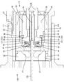
- FIG. 1 is a perspective view showing a state in which the housing is held in the second posture with respect to the outer member in the connector according to the first embodiment.
- FIG. 2 is a perspective view showing a state in which the housing is held in the first posture with respect to the outer member.
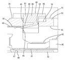
- FIG. 3 is a side sectional view showing a state in which the retainer is held in the main locking position with respect to the housing and the housing is held in the second posture with respect to the outer member.
- FIG. 4 is a side sectional view showing a state in which the retainer is held in a semi-inserted state with respect to the housing and the housing is restricted from reaching the second posture with respect to the outer member.
- FIG. 5 is a side sectional view showing a state in which the connector is fitted with the mating connector and the terminal fitting is connected to the circuit board.
- FIG. 6 is a perspective view of the outer member.
- FIG. 7 is a perspective view of the guide member.
- FIG. 8 is a perspective view of a pair of housings on the top and bottom.
- FIG. 9 is a view of the housing as viewed from the connection surface side.
- FIG. 10 is a perspective view of a pair of retainers on the top and bottom.
- FIG. 11 is an enlarged cross-sectional view showing a state in which the retainer is held in the temporarily locked position with respect to the housing.
- FIG. 12 is an enlarged cross-sectional view showing a state in which the locking portion of the outer member is locked to the standby locking receiving portion of the guide member.
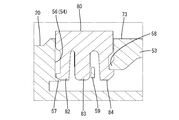
- FIG. 13 is an enlarged cross-sectional view showing a state in which the terminal fitting is temporarily locked by the lance of the retainer when the retainer is in the temporary locking position in the connector according to the second embodiment.
- the connectors of the present disclosure are (1) A terminal fitting connected to a circuit board, a housing for accommodating the terminal fitting, a substrate accommodating portion for accommodating the circuit board in the housing, a retainer mounting hole provided in the housing, and the retainer mounting. A retainer that is inserted into the hole to lock the terminal fitting is provided, and the thermal expansion difference between the retainer and the circuit board is set to be larger than the thermal expansion difference between the housing and the circuit board. According to the above configuration, since the difference in thermal expansion between the housing and the circuit board can be reduced or eliminated, it is possible to prevent the housing and the circuit board from being displaced due to the difference in thermal expansion.
- the retainer can be designed independently of the circuit board, the degree of freedom in designing the retainer can be increased, and the cost of the connector can be reduced and the mechanical strength can be improved.
- the housing and the circuit board are made of the same material. According to this configuration, the difference in thermal expansion between the housing and the circuit board is eliminated, and the housing and the circuit board can be deformed in the same manner in a thermal environment, so that the connection resistance between the circuit board and the terminal fitting increases. It can be reliably prevented.
- the retainer is preferably made of a material having tougher than the housing. According to this configuration, there is little concern that the retainer will be damaged when the terminal fitting is locked, and the locked state of the retainer and the terminal fitting can be maintained satisfactorily.
- the housing has a cavity into which the terminal fitting is inserted, and the retainer is movably held at a temporary locking position and a main locking position with respect to the housing, and the temporary locking position. Then, it is inserted shallowly into the retainer mounting hole, is inserted deeper into the retainer mounting hole than the temporary locking position at the main locking position, and the retainer protrudes into the cavity at the temporary locking position. It is preferable to have a flexible and deformable lance that temporarily locks the terminal fittings located in the cavity, and a retaining portion that secondarily locks the terminal fittings at the main locking position. ..
- the housing is made of the same LCP (liquid crystal polymer) resin as the circuit board, it is difficult to provide the housing with a lance that temporarily locks the terminal fittings due to the vulnerability of the LCP. be.
- the lance of the retainer can temporarily lock the terminal fitting when the retainer is in the temporary locking position.
- the retainer is made of a material having tougher than the housing, the lance can be formed with good moldability.
- the connector 10 includes a housing 20, an outer member 21, a terminal fitting 60, and a retainer 80.
- the outer member 21 can be fitted to the mating connector 100.
- the front side is the side on which the connector 10 and the mating side connector 100 (hereinafter, referred to as both connectors 10 and 100) face each other at the start of fitting.
- the mating side connector 100 has a hood portion 110 and a circuit board 120.
- the circuit board 120 is made of an LCP (Liquid Crystal Polymer) resin or the like as a base material, except for the conductive portion 121.
- the material constituting the circuit board 120 may be an LCP resin as a base material to which glass fibers or other additives are added.
- the hood portion 110 is made of synthetic resin.
- a hole-shaped lock receiving portion 111 is provided so as to penetrate through the front end side of the upper wall portion of the hood portion 110.
- the hood portion 110 and the circuit board 120 are attached to a case (not shown). The relative positions of the hood portion 110 and the circuit board 120 are maintained constant via the case.
- the circuit board 120 is arranged in the hood portion 110.
- the conductive portion 121 has a connecting member 122 formed by bending a metal plate material.
- the connecting member 122 is fitted to a protruding portion projecting by molding or the like on the plate surface (surface) of the circuit board 120.
- the connecting member 122 is connected to a conductive path (not shown) of the circuit board 120.
- a plurality of connecting members 122 are arranged upright on the plate surface of the circuit board 120 in a state of being arranged side by side.
- the housing 20 is arranged inside the outer member 21.
- the housings 20 are provided in pairs in the vertical direction (vertical direction in FIG. 1).
- the housing 20 is displaceably incorporated into the outer member 21 in a first posture (state shown in FIG. 2) and a second posture (state shown in FIG. 1).
- the first posture is a posture in which the housing 20 is arranged horizontally along the front-rear direction.
- the second posture is a posture in which the housing 20 is arranged so as to be inclined in a direction intersecting the front-rear direction.
- a guide member 22 is provided between the outer member 21 and the housing 20 to ensure the stability of the displacement operation of the housing 20.
- the retainer 80 is attached to the housing 20.
- the retainers 80 are provided in pairs in the vertical direction so as to correspond to the housing 20.
- a plurality of terminal fittings 60 are housed in the housing 20.
- the retainer 80 locks the terminal fitting 60 and restricts the terminal fitting 60 from coming out of the housing 20.
- the terminal fitting 60 is electrically connected to the conductive portion 121 of the circuit board 120.
- the terminal fitting 60 is displaced from the position facing the plate surface of the circuit board 120 toward the conductive portion 121.
- the outer member 21 is made of synthetic resin, and as shown in FIG. 6, has a box shape that is open to the front and rear as a whole.
- the outer member 21 is made of the same material as the housing 20 (a material based on LCP resin as described later). However, in consideration of cost and the like, the same material as the retainer 80 (a material based on a PBT (Polybutylene terephthate) resin) or a material different from the retainer 80 and the housing 20 may be used.
- the outer member 21 has a pair of side walls 23 facing each other on the left and right sides, an upper wall 24 erected between the upper ends of both side walls 23, and a lower wall 25 erected between the lower ends of both side walls 23. There is.
- a housing accommodation space 26 is provided inside the outer member 21.
- the side walls 23 are provided with a pair of upper and lower guide grooves 27 for guiding the displacement operation of the housing 20.
- the guide groove 27 penetrates the corresponding side wall 23 in the wall thickness direction and communicates with the housing accommodation space 26 inside.
- the guide groove 27 is arranged shortly along the front-rear direction from the separation region, a straight region arranged along the front-rear direction at the rear portion, a separation region inclined so as to be separated in the vertical direction from the straight region to the front, and a separation region. It has an apex region to be formed and an approach region that is inclined forward from the apex region so as to approach the upper and lower central portions of the side wall 23.
- the straight line region is open at the rear end of the outer member 21.
- a pair of upper and lower insertion grooves 28 are provided at both upper and lower ends of the inner surface of both side walls 23.
- the insertion groove 28 is a bottomed groove that is closed to the outer surface of the side wall 23, extends in the front-rear direction, and opens at the front end of the side wall 23.
- Elastic locking portions 29 are provided at both upper and lower ends of both side walls 23 so as to cut out the bottom surface of the insertion groove 28.
- the elastic locking portion 29 can be flexed and deformed inward and outward (left and right) with the rear end portion as a fulcrum. As shown in FIG. 12, the front end portion (tip portion) of the elastic locking portion 29 is provided with a locking projection 31 projecting inward.
- An insertion portion 41, which will be described later, of the guide member 22 is inserted into the insertion groove 28.
- the elastic locking portion 29 locks the locking receiving portions 42, 43, 44 described later of the guide member 22.
- the upper wall 24 and the lower wall 25 are provided at the rear portion of the outer member 21.
- the upper and lower surfaces of the outer member 21 have an opening 32 in front of the upper wall 24 and the lower wall 25.
- the opening 32 communicates with the housing accommodation space 26 inside.
- the left and right ends of the opening 32 are partitioned by both side walls 23.
- the front of the opening 32 is open.
- the rear portion of the opening 32 is partitioned by the front ends of the upper wall 24 and the lower wall 25.
- the front ends of the upper wall 24 and the lower wall 25 are edges arranged linearly along the width direction (left-right direction), and are configured as an interference portion 33 capable of interfering with the retainer 80 in the semi-inserted state described later. Will be done.
- the housing 20 in an inclined posture, which will be described later, enters the opening 32 and escapes.
- the upper wall 24 is provided with a lock arm 34 that can be flexed and deformed.
- the front end, which is the bending fulcrum of the lock arm 34, constitutes the left and right central portions of the interference portion 33.
- the guide member 22 is made of synthetic resin, and as shown in FIG. 7, has a box shape that is open to the front and rear as a whole.
- the guide member 22 is arranged inside the outer member 21 and outside the housing 20.
- the guide member 22 is displaceable with respect to the outer member 21 in synchronization with the housing 20.
- the upper and lower surfaces of the guide member 22 have a window portion 35 that opens rectangularly in a plan view and a bottom view.
- the periphery of the window portion 35 is partitioned by a rectangular frame portion on the upper and lower surfaces of the guide member 22.
- the periphery of the front surface of the guide member 22 is also partitioned by a rectangular frame portion including the left and right side wall portions.
- the window portion 35 communicates with the opening 32 in a state of being arranged inside the outer member 21.
- the inclined housing 20 enters the window 35 and escapes.
- the guide member 22 has a partition wall 36 erected between the upper and lower central portions of the left and right side wall portions. As shown in FIG. 3, the partition wall 36 has a horizontal plate shape along the front-rear direction. In a state where the guide member 22 is arranged inside the outer member 21, the housing accommodation space 26 is vertically divided by the partition wall 36. The tip (front end) of the partition wall 36 is arranged linearly along the width direction behind the front end of the side wall portion.
- a pair of upper and lower guide grooves 37 for receiving the guide pins 71 described later of the housing 20 are provided on the left and right side wall portions of the guide member 22.
- the guide groove 37 has a linear region extending in the front-rear direction and opening to the rear end of the side wall portion, and a separation region extending in a direction away from the front end of the immediately preceding region. Front and rear guide pins 71 are inserted into both ends of the linear region of the guide groove 37. In the separation region of the guide groove 37, the guide pin 71 on the front side is displaceably arranged when the housing 20 takes an inclined posture with respect to the outer member 21.
- Elastic arm portions 38 for partitioning the straight portion of the guide groove 37 are provided on the left and right side wall portions of the guide member 22. At the rear end of the elastic arm 38, a claw-shaped holding protrusion 39 projecting inside the rear of the guide groove 37 is provided.
- the elastic arm portion 38 is flexible and deformable with the front end portion as a fulcrum.
- the left and right side wall portions of the guide member 22 are provided with a pair of upper and lower insertion portions 41 that continuously project laterally from the upper and lower surfaces.
- the insertion portion 41 has a rib shape extending in the front-rear direction.
- the insertion portion 41 is provided with a standby locking receiving portion 42, an assembling locking receiving portion 43, and a restricting locking receiving portion 44.
- These locking receiving portions 42, 43, 44 are recessed on the side surface (side end surface) of the inserting portion 41 at intervals in the front-rear direction.
- a standby locking receiving portion 42, an assembling locking receiving portion 43, and a regulating locking receiving portion 44 are provided side by side in this order from the front side.
- the guide member 22 is assembled to the outer member 21 from the front, and can reach the assembled position via the movement restricting position. Further, the guide member 22 can be advanced relative to the outer member 21 to reach the standby position.
- the restricting locking receiving portion 44, the assembling locking receiving portion 43, and the standby locking receiving portion 42 are the locking projections 31 of the elastic locking portion 29 at the movement restricting position, the assembling position, and the standby position, respectively. Accept.
- the terminal fitting 60 is integrally formed by bending a conductive metal plate or the like. As shown in FIG. 3, the terminal fitting 60 includes a base portion 61 extending in the front-rear direction, a box-shaped terminal body 62 provided at the front portion of the base portion 61, and an open barrel-shaped barrel portion 63 provided at the rear portion of the base portion 61. And have. The barrel portion 63 is crimped and connected to the end portion of the electric wire 90.
- An elastic contact piece 64 that can be flexed and deformed is arranged in the terminal body 62. The elastic contact piece 64 stands up from the front end of the base portion 61 and then is folded back to form a long shape in the vertical direction as a whole.
- the terminal body 62 also has a shape that is long in the vertical direction corresponding to the elastic contact piece 64.
- the trailing edge of the terminal body 62 is provided with a retaining portion 65 along the vertical direction.
- the retaining portion 65 is formed long in the vertical direction due to the height difference between the terminal body 62 and the barrel portion 63.
- the retaining portion 65 is locked to the retaining portion 85 of the retainer 80, which will be described later.
- the terminal body 62 is provided with a hole in the base 61 that allows the connecting member 122 of the circuit board 120 to enter.
- the elastic contact piece 64 has a contact portion 66 at a position facing the hole of the base portion 61.
- the housing 20 is made of synthetic resin, and as shown in FIG. 8, has a flat shape in the width direction as a whole.
- the material constituting the housing 20 is the same material as that of the circuit board 120, and is made of LCP resin as a base material.
- the housing 20 may be made of a material different from that of the circuit board 120, and is preferably made of a material having a coefficient of thermal expansion close to the coefficient of thermal expansion (linear expansion coefficient) of the material constituting the circuit board 120. It is good to be there.
- the material constituting the housing 20 may be an LCP resin as a base material to which glass fibers or other additives are added.
- the housing 20 is provided with a plurality of cavities 45 (only one is shown in FIG. 3).
- the cavities 45 are arranged in a row in the width direction.
- the cavity 45 has a rectangular cross-sectional shape that is long in the vertical direction, extends in the front-rear direction, and opens at the rear end of the housing 20.
- the terminal fitting 60 is inserted into each cavity 45 from the rear.
- an inspection window 47 for inspecting the continuity of the terminal fitting 60 is provided on the front wall 46 of the housing 20 for each cavity 45.
- the front surface of each cavity 45 is closed by the front wall 46 of the housing 20, except for each inspection window 47.
- the housing 20 has a connection port 48 on an inner wall 52 facing the base 61 of the terminal fitting 60 inserted into each cavity 45.
- the connection port 48 is a slit-shaped hole long in the width direction, penetrates the inner wall 52, and communicates with each cavity 45.
- the connection member 122 of the circuit board 120 is inserted into the connection port 48.
- the connecting member 122 enters the terminal body 62 from the connection port 48 through the hole of the base 61, and comes into contact with the contact portion 66 of the elastic contact piece 64 in the terminal body 62.
- the inner wall 52 of the housing 20 has a locking hole 49 behind the connection port 48.
- a protrusion 67 cut up and raised from the base 61 enters the locking hole 49.
- the outer surface of the inner wall 52 opposite to the cavity 45 is configured as a flat connection surface 51 through which the connection port 48 opens.
- the housing 20 has a retainer mounting hole 54 in an outer wall 53 located on the opposite side of the inner wall 52 via each cavity 45.
- the retainer mounting hole 54 is a rectangular hole long in the width direction, penetrates the outer wall 53, and communicates with each cavity 45.
- the retainer 80 is inserted into the retainer mounting hole 54.
- the rear portion of the retainer mounting hole 54 has a stepped support surface 55 capable of supporting the rear portion 86 of the retainer 80 in the middle of the outer wall 53 in the thickness direction.
- a pair of retainer locking holes 56 are provided at both left and right ends of the retainer mounting holes 54.
- the retainer locking hole 56 has a region extending forward in a slit groove shape.
- the housing 20 has a claw-shaped main locking portion 57 projecting from the front end of the retainer locking hole 56, and a claw-shaped temporary locking portion 58 projecting from the rear end of the retainer mounting hole 54. I have it set up.
- the temporary locking portion 58 is larger than the main locking portion 57 and is located outside the main locking portion 57 (upper side in FIG. 11).
- the housing 20 projects a guide rib 59 extending in the vertical direction in the middle of the retainer mounting hole 54 in the front-rear direction.
- the outer surface of the outer wall 53 opposite to the cavity 45 is configured as a flat surface 73. As shown in FIG. 3, one surface 73 of the outer wall 53 is arranged so as to face the interference portion 33 of the outer member 21 when the housing 20 is in the second posture described later.
- a pair of front and rear guide pins 71 are provided on both the left and right sides of the housing 20.
- Each guide pin 71 has a columnar shape, and is projected on both the left and right sides of the housing 20 at intervals in the front-rear direction.
- a flange portion 72 is provided at the tip of each guide pin 71 so as to project over the entire circumference.
- the retainer 80 is made of synthetic resin, and as shown in FIG. 10, has a main body portion 81 extending long in the width direction and locking portions 82, 83, 84 connected to both left and right ends of the main body portion 81.
- the material constituting the retainer 80 is different from the housing 20 and the circuit board 120, and is composed of a material having a coefficient of thermal expansion that is different from the coefficient of thermal expansion (linear expansion coefficient) of the material constituting the circuit board 120.
- the difference in the coefficient of thermal expansion of each material of the retainer 80 and the circuit board 120 is set to be larger than the difference in the coefficient of thermal expansion of each material of the housing 20 and the circuit board 120.
- the material constituting the retainer 80 is based on PBT resin.
- the material constituting the retainer 80 may be a PBT resin as a base material to which glass fibers or other additives are added.
- the retainer 80 is formed in a size that fits in the retainer mounting hole 54.
- the retainer 80 has a temporary locking position (see FIG. 4) that is shallowly inserted into the retainer mounting hole 54 with respect to the housing 20, and a main locking that is inserted deeper into the retainer mounting hole 54 than in the temporary locking position. It is held movably in position (see FIGS. 3 and 5).
- the front surface of the main body 81 is a vertical surface along the vertical direction and the width direction, and is configured as a retaining portion 85. As shown in FIG. 5, the retaining portion 85 faces the retaining portion 65 of the terminal fitting 60 inserted into each cavity 45 at the main locking position, and locks each terminal fitting 60 collectively.
- the rear portion 86 of the main body portion 81 is arranged one step lower than the front portion 87 via a step.
- the rear portion 86 of the main body portion 81 is supported by the support surface 55 of the retainer mounting hole 54 at the main locking position.
- the inner surface of the front portion 87 of the main body portion 81 extends in the front-rear direction at a position corresponding to the partition wall portion partitioning between the cavities 45 in the housing 20.
- a plurality of ribs 88 are provided side by side.
- the outer surface of the main body 81 (the surface facing the outside of the housing 20 when assembled to the housing 20) is a flat horizontal surface in the front-rear direction and the left-right direction.
- the locking portions 82, 83, 84 are inserted into the retainer locking holes 56.
- the locking portions 82, 83, 84 have the main locking arm 82, the guide piece 83, and the temporary locking arm 84, which are arranged side by side in the front-rear direction.
- the guide piece 83 is connected to the left and right ends of the front portion 87, and has a strip-like shape protruding inward from the main body portion 81 (the side where the terminal fitting 60 is located while being assembled to the housing 20). It is in the form of.
- the locking arm 82 has an arm-like shape that projects inward from a base end portion connected to the front side of the guide piece 83.
- the locking arm 82 can be bent and deformed in the front-rear direction with the base end portion as a fulcrum.
- the tip of the locking arm 82 is provided with a claw-shaped portion that projects forward.
- the temporary locking arm 84 is connected to the left and right ends of the rear portion 86, and has an arm-like shape that protrudes inward from the main body portion 81.
- the temporary locking arm 84 can be bent and deformed in the front-rear direction with the base end portion connected to the main body 81 as a fulcrum.
- the tip of the temporary locking arm 84 is provided with a claw-shaped portion that projects rearward.
- the temporary locking arm 84 is configured to have a larger front-rear width than the main locking arm 82.
- a pair of upper and lower housings 20 are inserted into the housing accommodation space 26 of the outer member 21 from the rear.
- the front and rear guide pins 71 are inserted into the corresponding guide grooves 27.
- the guide pin 71 on the front side is arranged in the approach region from the linear region of the guide groove 27 via the separation region and the top region.
- the rear guide pin 71 is arranged in the straight region of the guide groove 27.
- the guide member 22 is inserted into the outer member 21 from the front.
- the insertion operation of the guide member 22 is guided by the insertion portion 41 sliding on the groove surface of the insertion groove 28.
- the guide pin 71 is inserted into the guide groove 37.
- the elastic locking portion 29 is bent and deformed.
- the guide member 22 reaches the movement restricting position in the process of inserting the guide member 22, the locking projection 31 fits into the restricting locking receiving portion 44, and the elastic locking portion 29 elastically returns.
- the guide pin 71 on the rear side interferes with the holding projection 39, and the elastic arm portion 38 is flexed and deformed.
- the elastic arm portion 38 elastically returns, and the holding projection 39 wraps around behind the guide pin 71 on the rear side.
- the guide pin 71 on the front side is positioned so as to hit the front end of the guide groove 37. Therefore, the guide member 22 is assembled in a state where the movement in the front-rear direction is restricted with respect to the housing 20 at the assembly position. Then, when the guide member 22 reaches the assembling position, the locking projection 31 of the elastic locking portion 29 is fitted into the assembling locking receiving portion 43, and the guide member 22 is in the assembling position with respect to the outer member 21. Is held in.
- the pair of upper and lower housings 20 take a horizontal first posture and form a substrate accommodating portion 50 between the connecting surfaces 51 of each other (see FIG. 2).
- the substrate accommodating portion 50 has an opening dimension in the vertical direction corresponding to the plate thickness of the circuit board 120 in the first posture.
- the retainer 80 is inserted into the retainer mounting hole 54 from above and below the outer member 21 through the opening 32 and the window 35.
- the claw-shaped portion of the temporary locking arm 84 is arranged so as to hit the temporary locking portion 58 from the inside, and the retainer 80 is arranged from the retainer mounting hole 54. Escape is regulated. Further, when the retainer 80 reaches the temporary locking position, the claw-shaped portion of the locking arm 82 is arranged so as to hit the locking portion 57 from the outside, and the movement of the retainer 80 to the locking position is restricted. NS.
- the moving operation of the retainer 80 is guided by a guide rib 59 arranged along the guide piece 83.
- the main body 81 does not enter each cavity 45 except for each rib 88, and is retracted from each cavity 45 and arranged.
- the outer portion of the main body portion 81 is positioned so as to project outward from one surface 73 of the outer wall 53.
- the rear portion 86 of the main body portion 81 is arranged entirely outside the one surface 73 of the outer wall 53 apart from the support surface 55 (see FIG. 4).
- the terminal fitting 60 is inserted into each cavity 45 from the rear.
- the terminal fitting 60 since the lance does not protrude into the cavity 45, the terminal fitting 60 is smoothly inserted into the cavity 45 without receiving the insertion resistance from the lance.
- the front wall portion of the terminal body 62 hits the front wall 46 of the housing 20, and the insertion operation of the terminal fitting 60 is restricted.
- the protrusion 67 enters the locking hole 49 and is hooked to the rear end of the locking hole 49, so that the terminal fitting 60 is restricted from coming out of the cavity 45.
- the contact portion 66 of the elastic contact piece 64 is arranged so as to face the hole of the base portion 61 and the connection port 48 of the housing 20 from the outside.
- the retainer 80 is pushed into the main locking position with respect to the housing 20.
- the claw-shaped portion of the main locking arm 82 is arranged so as to hit the main locking portion 57 from the inside, and the return movement of the retainer 80 to the temporary locking position is restricted. .. Further, when the retainer 80 reaches the main locking position, the rear portion 86 of the main body portion 81 hits the support surface 55, and the movement of the retainer 80 inward is restricted.
- the retaining portion 85 is arranged so as to hit the retaining portion 65 of the terminal body 62 in the vertical direction. As a result, the terminal fitting 60 is surely restricted from coming out of the cavity 45. Further, when the retainer 80 is in the main locking position, the entire retainer 80 is inserted into the retainer mounting hole 54. At this time, the outer surface of the main body 81 is arranged so as to be flush with the one surface 73 of the housing 20 or to be retracted inward from the one surface 73 of the housing 20.
- the housing 20 is displaced from the first posture to the second posture.
- the housing 20 can be displaced to the second posture by pressing the flange portion 72 of the guide pin 71 on the rear side rearward.
- the housing 20 and the guide member 22 are integrated, so that the locking projection 31 of the guide member 22 comes out of the locking receiving portion 43 for assembly.
- the elastic locking portion 29 is bent and deformed.
- the elastic locking portion 29 elastically returns, and the locking projection 31 fits into the standby locking receiving portion 42 (see FIG. 12).
- the guide member 22 is held by the outer member 21 at the standby position.
- the housing 20 is held by the outer member 21 in the second posture via the guide member 22.
- the front guide pin 71 is located at the top region of the guide groove 27, and the rear guide pin 71 is located at the rear end of the straight region of the guide groove 27.
- the pair of upper and lower housings 20 are arranged in a state of being open toward each other in the second posture.
- the substrate accommodating portion 50 formed between the connection surfaces 51 of each housing 20 expands the opening dimension in the vertical direction toward the front (see FIG. 3).
- the housing 20 does not protrude outward from the opening 32 even in the second posture, and maintains a state of being arranged inside the outer member 21.
- the connection surface 51 of the housing 20 is arranged so as to face the inside front in the second posture.
- One side 73 of the housing 20 is arranged closer to the interference portion 33 in the second posture than in the first posture.
- the connector 10 is shipped to the site where the fitting work with the mating connector 100 is performed with the housing 20 held in the second posture.
- the retainer 80 does not reach the main locking position but is in the middle position from the temporary locking position to the main locking position, or is held at the temporary locking position (in these cases). Is referred to as a semi-inserted state), the outer portion of the main body 81 is in a state of protruding outward from one surface 73 of the housing 20. Therefore, in the process of the housing 20 reaching the second posture, one surface 73 of the housing 20 approaches the interference portion 33, so that the outer portion of the main body portion 81 interferes with the interference portion 33, and the housing 20 reaches the second posture. (See Figure 4).
- the guide member 22 does not reach the standby position, and the elastic locking portion 29 and the standby locking receiving portion 42 do not enter the locked state, so that the outer portion of the main body portion 81 interferes with the interference portion 33.
- the tilted posture of the housing 20 cannot be maintained. Therefore, the guide pin 71 on the front side is displaced along the inclination of the approaching region of the guide groove 27, and the housing 20 tries to return to the first posture which is the horizontal posture.
- the retainer 80 is in the semi-inserted state before shipping to the site where the fitting work of both connectors 10 and 100 is performed. Can be detected.
- the housing 20 is held in the second posture with respect to the outer member 21, and the state in which the retainer 80 is in the main locking position is guaranteed. ..
- the circuit board 120 is inserted into the substrate accommodating portion 50. Then, the end surface of the circuit board 120 hits the tip of the partition wall 36 of the guide member 22, and a rearward pushing force is applied to the guide member 22. Then, the locking projection 31 comes out of the standby locking receiving portion 42, and the elastic locking portion 29 is bent and deformed.
- the circuit board 120 pushes in the guide member 22, and the guide member 22 retracts with respect to the outer member 21 together with the housing 20.
- the front guide pin 71 is displaced forward along the approaching region of the guide groove 27, and the inclination angle of the housing 20 gradually decreases.
- the locking projection 31 is displaced forward of the insertion portion 41, and the elastic locking portion 29 is elastically restored.
- the housing 20 takes the first posture in the horizontal posture, and the front and rear guide pins 71 shift to the straight region of the guide groove 27.
- the housing 20 gradually approaches the plate surface of the circuit board 120 in the process from the second posture to the first posture, and the connection member 122 of the circuit board 120 passes through the hole of the base 61 and the connection port 48 of the housing 20 to the terminal body 62. Enter inside.
- the connecting member 122 comes into contact with the contact portion 66 while bending the elastic contact piece 64.
- the terminal fitting 60 is connected to the conductive portion 121 of the circuit board 120. Since the elastic contact piece 64 does not come into contact with the end face corner portion of the circuit board 120, it is not damaged due to interference with the end face corner portion of the circuit board 120. Therefore, the connection state between the terminal fitting 60 and the circuit board 120 can be satisfactorily realized. Further, when the terminal fitting 60 and the circuit board 120 are connected, the protruding portion of the lock arm 34 is fitted into the lock receiving portion 111 of the hood portion 110, and both the connectors 10 and 100 are held in the fitted state.
- the circuit board 120 is arranged so as to be sandwiched between the board accommodating portions 50 between the connection surfaces 51 of the pair of upper and lower housings 20.
- the housing 20 and the circuit board 120 are made of the same material, and there is no difference in the coefficient of linear expansion. Therefore, it is possible to prevent the relative positions of the housing 20 and the circuit board 120 from being displaced. Even if the housing 20 and the circuit board 120 are made of different materials, if the difference in the coefficient of thermal expansion between the housing 20 and the circuit board 120 is smaller than the difference in the coefficient of thermal expansion between the retainer 80 and the circuit board 120, the housing 20 The relative position between the circuit board and the circuit board 120 does not deviate significantly.
- the terminal fitting 60 assembled to the housing 20 can also maintain a constant relative position with respect to the circuit board 120, the contact portion 66 of the terminal fitting 60 slides on the connecting member 122, and the connection resistance increases. The situation can be prevented.
- the retainer 80 is made of PTB resin or the like. Therefore, the retainer 80 is excellent in toughness, and the state in which the retaining portion 85 locks the retaining portion 65 of the terminal body 62 can be satisfactorily maintained.
- the thermal expansion difference between the housing 20 and the circuit board 120 is smaller than the thermal expansion difference between the retainer 80 and the circuit board 120, the housing 20 and the circuit board 120 are heated. It is possible to prevent the position from shifting due to the difference in expansion. As a result, it is possible to prevent the connection resistance between the circuit board 120 and the terminal fitting 60 from increasing.
- the material of the retainer 80 is not limited to the material of the circuit board 120, the degree of freedom in designing the retainer 80 can be increased. As a result, the cost of the entire connector 10 can be reduced and the mechanical strength can be improved.
- the retainer 80 is made of PBT resin, which is tougher than the housing 20, the possibility of damage when locking the terminal fitting 60 can be reduced.
- one surface 73 of the housing 20 approaches the interference portion 33 and interferes with the retainer 80 in the semi-inserted state with the interference portion 33. Can be made to. Therefore, the housing 20 is restricted from reaching the second posture, and it can be detected that the retainer 80 is in the semi-inserted state. Therefore, it is possible to detect whether or not the retainer 80 is properly inserted before shipping the connectors 10 and 100 to the site where the fitting work is performed.
- the operation of detecting the semi-inserted state of the retainer 80 is linked with the operation of connecting the terminal fitting 60 to the surface of the circuit board 120, it is not necessary to perform each operation individually. , The work load can be reduced.
- the retainer 80 in the semi-inserted state can interfere with the interference portion 33, so that the interference portion 33 is housed. It is not necessary to have a shape protruding to the 20 side, and the interference portion 33 can be made into a simple shape.
- FIG. 13 shows Example 2 of the present embodiment.
- the shape of the retainer 80 is different from that of the first embodiment.
- Others are the same as in Example 1.
- the same or corresponding structure as that of the first embodiment will be designated by the same reference numerals as those of the first embodiment, and duplicate description will be omitted.
- the retainer 80 has a plurality of lances 89 on the inner surface of the front portion 87 of the main body portion 81 (the surface facing the terminal fitting 60 in the state of being assembled to the housing 20).
- the lances 89 are arranged side by side in the width direction at positions corresponding to the cavities 45 on the inner surface of the front portion 87 of the main body portion 81.
- the lance 89 has a proximal end portion at the rear end portion on the inner surface of the front portion 87 of the main body portion 81, and is in a form of cantileveringly projecting forward from the proximal end portion.
- the lance 89 is flexible and deformable with the base end portion as a fulcrum.
- the tip end portion (front end portion) of the lance 89 enters the cavity 45 and is arranged.
- the terminal body 62 interferes with the tip of the lance 89, and the lance 89 is bent and deformed.
- the terminal body 62 hits the front wall 46 of the housing 20 and the terminal fitting 60 is properly inserted into the cavity 45, the lance 89 elastically returns, and the tip of the lance 89 faces the retaining portion 65 of the terminal body 62. Is placed. In this way, the terminal fitting 60 is temporarily locked by the lance 89 of the retainer 80.
- the retaining portion 85 of the main body 81 is arranged together with the lance 89 so as to face the retaining portion 65 of the terminal main body 62.
- the terminal fitting 60 is secondarily locked by the retaining portion 85, and is held in the cavity 45 in a state where it is securely secured.
- the housing 20 is made of LCP resin, which is the same material as the circuit board 120, as a base material in order to eliminate the difference in thermal expansion between the housing 20 and the circuit board 120.
- LCP resin which is the same material as the circuit board 120
- the housing 20 made of LCP resin as a base material tends to be relatively brittle, there is a circumstance that it is difficult to form a lance 89 that bends and deforms.
- the lance 89 is formed on the retainer 80 made of a PBT resin having toughness against brittleness as a base material. Therefore, the lance 89 can be formed on the retainer 80 without any trouble. In addition, the elastic locking function of the lance 89 can be satisfactorily exerted.
- the housing is arranged so as to be relatively displaceable inside the outer member, but in another embodiment, the connector does not have the outer member and the housing is It may be configured to be inserted into the hood portion of the mating connector independently.
- the connector has a pair of upper and lower housings and a board accommodating portion is provided between the pair of upper and lower housings, but in another embodiment, the connector has one housing and is inside the housing. The configuration may be such that a substrate accommodating portion is provided.
- the circuit board and the housing are made of a material based on LCP resin
- the retainer is made of a material based on PBT resin.
- the retainer and the circuit are used.
- the type of resin for the retainer, housing, and circuit board is not particularly limited as long as the difference in thermal expansion from the substrate is larger than the difference in thermal expansion between the housing and the circuit board.
Landscapes
- Connector Housings Or Holding Contact Members (AREA)
Priority Applications (2)
| Application Number | Priority Date | Filing Date | Title |
|---|---|---|---|
| US17/911,907 US20230139124A1 (en) | 2020-03-26 | 2021-03-05 | Connector |
| CN202180023264.7A CN115315861A (zh) | 2020-03-26 | 2021-03-05 | 连接器 |
Applications Claiming Priority (2)
| Application Number | Priority Date | Filing Date | Title |
|---|---|---|---|
| JP2020055509A JP7417196B2 (ja) | 2020-03-26 | 2020-03-26 | コネクタ |
| JP2020-055509 | 2020-03-26 |
Publications (1)
| Publication Number | Publication Date |
|---|---|
| WO2021192921A1 true WO2021192921A1 (ja) | 2021-09-30 |
Family
ID=77890033
Family Applications (1)
| Application Number | Title | Priority Date | Filing Date |
|---|---|---|---|
| PCT/JP2021/008659 Ceased WO2021192921A1 (ja) | 2020-03-26 | 2021-03-05 | コネクタ |
Country Status (4)
| Country | Link |
|---|---|
| US (1) | US20230139124A1 (https=) |
| JP (1) | JP7417196B2 (https=) |
| CN (1) | CN115315861A (https=) |
| WO (1) | WO2021192921A1 (https=) |
Families Citing this family (1)
| Publication number | Priority date | Publication date | Assignee | Title |
|---|---|---|---|---|
| JP7439608B2 (ja) * | 2020-03-26 | 2024-02-28 | 株式会社オートネットワーク技術研究所 | カードエッジコネクタ及び回路基板 |
Citations (5)
| Publication number | Priority date | Publication date | Assignee | Title |
|---|---|---|---|---|
| JPH10199603A (ja) * | 1997-01-10 | 1998-07-31 | Yazaki Corp | コネクタ |
| JP2001332324A (ja) * | 2000-05-23 | 2001-11-30 | Sumitomo Wiring Syst Ltd | 基板用コネクタ |
| JP2008117706A (ja) * | 2006-11-07 | 2008-05-22 | Auto Network Gijutsu Kenkyusho:Kk | カードエッジコネクタ |
| JP2014130722A (ja) * | 2012-12-28 | 2014-07-10 | Auto Network Gijutsu Kenkyusho:Kk | カードエッジコネクタ |
| JP2017050134A (ja) * | 2015-09-01 | 2017-03-09 | 日本圧着端子製造株式会社 | 雌コネクタ及びカードエッジコネクタ |
Family Cites Families (20)
| Publication number | Priority date | Publication date | Assignee | Title |
|---|---|---|---|---|
| US2711523A (en) * | 1952-07-23 | 1955-06-21 | Teleregister Corp | Multi-contact connector |
| US2811700A (en) * | 1956-05-14 | 1957-10-29 | Bell Telephone Labor Inc | Electrical connector for printed wiring board |
| US3130351A (en) * | 1961-09-14 | 1964-04-21 | George J Giel | Modular circuitry apparatus |
| US4449775A (en) * | 1978-12-27 | 1984-05-22 | Compaganie Internationale Pour L'informatique Cii-Honeywell Bull (Societe Anonyme) | Connector for portable objects such as credit cards |
| US4200349A (en) * | 1979-01-10 | 1980-04-29 | Fairchild Camera And Instrument Corporation | Low force printed circuit board connector apparatus |
| US5391972A (en) * | 1988-03-11 | 1995-02-21 | Gardner; Billy J. | Cordless tool battery housing and charging system |
| US5295852A (en) * | 1993-07-12 | 1994-03-22 | The Whitaker Corporation | Coplanar computer docking system |
| JP2833451B2 (ja) * | 1993-10-28 | 1998-12-09 | 住友電装株式会社 | カードエッジコネクタ |
| JP2833455B2 (ja) * | 1993-11-17 | 1998-12-09 | 住友電装株式会社 | カードエッジコネクタ |
| JPH10302909A (ja) * | 1997-04-23 | 1998-11-13 | Yazaki Corp | 低挿入力コネクタ |
| JP3669268B2 (ja) * | 2000-11-30 | 2005-07-06 | 住友電装株式会社 | コネクタ |
| JP4760683B2 (ja) * | 2006-11-20 | 2011-08-31 | 住友電装株式会社 | コネクタ |
| US7563118B1 (en) * | 2008-06-20 | 2009-07-21 | Delphi Technologies, Inc. | High temperature connector |
| US8951066B2 (en) * | 2011-07-22 | 2015-02-10 | Lear Corporation | Electrical connector |
| JP2015072868A (ja) * | 2013-10-04 | 2015-04-16 | モレックス インコーポレイテドMolex Incorporated | コネクタ |
| JP2018120687A (ja) * | 2017-01-24 | 2018-08-02 | 住友電装株式会社 | コネクタ |
| WO2020176910A1 (en) * | 2019-02-25 | 2020-09-03 | J.S.T. Corporation | Method for improving clearance and creepage in a high voltage connector assembly using a male or female terminal position assurance (tpa) device |
| US11456553B2 (en) * | 2019-09-19 | 2022-09-27 | J.S.T. Corporation | Low profile high voltage connector and method for assemblying thereof |
| JP7439608B2 (ja) * | 2020-03-26 | 2024-02-28 | 株式会社オートネットワーク技術研究所 | カードエッジコネクタ及び回路基板 |
| JP7396155B2 (ja) * | 2020-03-26 | 2023-12-12 | 株式会社オートネットワーク技術研究所 | コネクタ |
-
2020
- 2020-03-26 JP JP2020055509A patent/JP7417196B2/ja active Active
-
2021
- 2021-03-05 CN CN202180023264.7A patent/CN115315861A/zh active Pending
- 2021-03-05 WO PCT/JP2021/008659 patent/WO2021192921A1/ja not_active Ceased
- 2021-03-05 US US17/911,907 patent/US20230139124A1/en not_active Abandoned
Patent Citations (5)
| Publication number | Priority date | Publication date | Assignee | Title |
|---|---|---|---|---|
| JPH10199603A (ja) * | 1997-01-10 | 1998-07-31 | Yazaki Corp | コネクタ |
| JP2001332324A (ja) * | 2000-05-23 | 2001-11-30 | Sumitomo Wiring Syst Ltd | 基板用コネクタ |
| JP2008117706A (ja) * | 2006-11-07 | 2008-05-22 | Auto Network Gijutsu Kenkyusho:Kk | カードエッジコネクタ |
| JP2014130722A (ja) * | 2012-12-28 | 2014-07-10 | Auto Network Gijutsu Kenkyusho:Kk | カードエッジコネクタ |
| JP2017050134A (ja) * | 2015-09-01 | 2017-03-09 | 日本圧着端子製造株式会社 | 雌コネクタ及びカードエッジコネクタ |
Also Published As
| Publication number | Publication date |
|---|---|
| US20230139124A1 (en) | 2023-05-04 |
| JP2021157907A (ja) | 2021-10-07 |
| CN115315861A (zh) | 2022-11-08 |
| JP7417196B2 (ja) | 2024-01-18 |
Similar Documents
| Publication | Publication Date | Title |
|---|---|---|
| JP5026859B2 (ja) | 電気接続箱 | |
| KR102509668B1 (ko) | 회로 기판용 전기 커넥터 | |
| US7559808B2 (en) | Connector | |
| JP7480905B2 (ja) | コネクタ | |
| US7114998B2 (en) | Divided connector and connector assembly | |
| US10236608B2 (en) | Electrical connector for circuit boards | |
| US7223124B2 (en) | Connector and a method of assembling it | |
| US20130005174A1 (en) | Electrical connector | |
| US20180076548A1 (en) | Female-type electrical connector, male-type electrical connector, and electrical connector assembly utilizing same | |
| CN112652902A (zh) | 扁平型导体用电连接器 | |
| US8784133B2 (en) | Connector | |
| WO2021192921A1 (ja) | コネクタ | |
| KR20000017090A (ko) | 커넥터의 하우징 및 그것에 의해 제조된 커넥터 | |
| US7695325B2 (en) | Connector | |
| US7267569B2 (en) | Connector with a shorting terminal | |
| CN114930651A (zh) | 连接器 | |
| JP2894591B2 (ja) | 端子の構造 | |
| JP2008277037A (ja) | コネクタハウジング及びコネクタ | |
| JP2003282188A (ja) | コネクタ | |
| JP2001196134A (ja) | 嵌合検知用コネクタおよび、嵌合検知用端子 | |
| JP3541929B2 (ja) | コネクタ | |
| JP2024075244A (ja) | コネクタ | |
| JP7315404B2 (ja) | 平型導体用コネクタ | |
| WO2021182026A1 (ja) | カードエッジコネクタ | |
| US20240413561A1 (en) | Terminal Positioning Device |
Legal Events
| Date | Code | Title | Description |
|---|---|---|---|
| 121 | Ep: the epo has been informed by wipo that ep was designated in this application |
Ref document number: 21773449 Country of ref document: EP Kind code of ref document: A1 |
|
| NENP | Non-entry into the national phase |
Ref country code: DE |
|
| 122 | Ep: pct application non-entry in european phase |
Ref document number: 21773449 Country of ref document: EP Kind code of ref document: A1 |