WO2021187614A1 - 物品取得ゲーム装置 - Google Patents
物品取得ゲーム装置 Download PDFInfo
- Publication number
- WO2021187614A1 WO2021187614A1 PCT/JP2021/011272 JP2021011272W WO2021187614A1 WO 2021187614 A1 WO2021187614 A1 WO 2021187614A1 JP 2021011272 W JP2021011272 W JP 2021011272W WO 2021187614 A1 WO2021187614 A1 WO 2021187614A1
- Authority
- WO
- WIPO (PCT)
- Prior art keywords
- crane
- plate
- prize
- game device
- unit
- Prior art date
- Legal status (The legal status is an assumption and is not a legal conclusion. Google has not performed a legal analysis and makes no representation as to the accuracy of the status listed.)
- Ceased
Links
Images



Classifications
-
- G—PHYSICS
- G07—CHECKING-DEVICES
- G07F—COIN-FREED OR LIKE APPARATUS
- G07F17/00—Coin-freed apparatus for hiring articles; Coin-freed facilities or services
- G07F17/32—Coin-freed apparatus for hiring articles; Coin-freed facilities or services for games, toys, sports, or amusements
- G07F17/3286—Type of games
- G07F17/3297—Fairground games, e.g. Tivoli, coin pusher machines, cranes
-
- A—HUMAN NECESSITIES
- A63—SPORTS; GAMES; AMUSEMENTS
- A63F—CARD, BOARD, OR ROULETTE GAMES; INDOOR GAMES USING SMALL MOVING PLAYING BODIES; VIDEO GAMES; GAMES NOT OTHERWISE PROVIDED FOR
- A63F9/00—Games not otherwise provided for
- A63F9/30—Capturing games for grabbing or trapping objects, e.g. fishing games
Definitions
- the present invention relates to an article acquisition game in which an article such as a prize is moved and acquired.
- a stage game field
- prizes particles
- the player operates the crane by making full use of the operating rod or various buttons. If the prize can be grasped by the crane and moved to the drop opening, the player can obtain the prize (see Patent Document 1).
- the present invention has been completed after reexamining the interests peculiar to the crane game, and its main purpose is to further enhance the interests when the crane approaches the drop port (the destination for moving the prize) in the crane game device.
- the purpose is to provide technology for deepening.
- the article acquisition game device of the present invention is provided in a play space, has a game field having a first area on which an article to be acquired is placed and a second area as a destination for moving the article, and a crane for gripping the article. It also includes an operation unit that receives an operation from the player, a crane control unit that drives the crane according to the operation, and a boundary detection unit that detects the boundary position of the second region. The crane control unit changes the gripping force of the crane according to the boundary position of the second region.
- the article acquisition game device of the present invention is provided in a play space, has a game field having a first area on which an article to be acquired is placed and a second area as a destination for moving the article, and a crane for gripping the article. And an operation unit that receives an operation from the player, and a crane control unit that drives the crane according to the operation.
- the shape of the second area can be changed.
- the crane control unit changes the gripping force of the crane according to the shape of the second region.
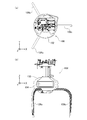
- FIG. 14A is a top view of the crane at the time of initial setting.
- FIG. 14B is a front view of the crane at the time of initial setting.
- FIG. 15A is a top view of the crane when rotated by 30 degrees.
- FIG. 15B is a front view of the crane when rotated by 30 degrees.
- FIG. 16A is a top view of the crane when the design cover is adjusted.
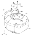
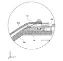
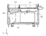
- FIG. 16B is a front view of the crane when the design cover is adjusted. It is an exploded perspective view around the design cover of the crane. It is a side sectional view around the design cover of the crane. It is a side sectional view of a storage box.
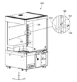
- FIG. 1 is a perspective view of the crane game device 100.
- the crane game device 100 is generally installed in an amusement park, a game center, or other amusement facility.
- the left-right direction of the crane game device 100 when viewed from the player will be the X direction
- the front-back direction will be the Y direction
- the up-down direction will be the Z direction.
- the crane game device 100 includes a rectangular parallelepiped base 102 and a box-shaped prize accommodating portion 104 provided on the base 102.
- a play space S is formed inside the prize accommodating portion 104, and a prize mounting stand 106 (game field) is provided.
- a prize mounting stand 106 (game field) is provided on the prize stand 106.
- On the prize stand 106 in addition to prizes such as stuffed animals and miscellaneous goods, color balls for decorating the prize stand 106 are arranged (described later).
- a crane 108 is provided above the prize mounting table 106. The crane 108 can move back and forth, left and right, and up and down in the play space S to grip / release the prize.
- the front surface and left and right sides of the prize storage unit 104 are covered with transparent glass. The visibility of the prize from the outside is taken into consideration.
- a camera that captures the prize mounting table 106 from above may be installed on the ceiling surface of the prize storage unit 104.
- a glass door 110 is provided on the front surface of the prize storage unit 104, and an operator (clerk) can open the door 110 to arrange the prize in the prize storage unit 104.
- the prize mounting table 106 is divided into a mounting area 112 (first area) and a drop port 114 (second area). If the prize is placed in the mounting area 112 and the player can carry the prize from the mounting area 112 to the drop port 114, the prize can be obtained.
- a shielding plate 128 is installed between the mounting area 112 and the drop port 114. The shielding plate 128 prevents the prize or the color ball in the mounting area 112 from rolling down to the drop port 114.
- a prize outlet 116 for taking out the prize that has fallen from the drop port 114 is formed on the front surface of the base 102.
- An operation unit 118 and a setting display unit 120 are provided on the front side of the base 102.
- the player inserts a coin into the coin slot or touches an IC card charged with electronic money to the IC card reader.
- the surface on which the operation unit 118 and the like are installed in other words, the surface on the side where the player is located is referred to as "front”, and is on the back side (Y-axis positive direction side) when viewed from the player.
- the surface is called the "back”.
- the operation unit 118 includes an operation rod 122 for the player to move the crane 108 back and forth and left and right to determine the descent point, and a grip button 124 for lowering the crane 108 to grip the prize.
- a touch panel is installed on the setting display unit 120.
- the setting display unit 120 functions as a "setting input unit” for the operator (clerk) to input game setting information, and is an “information display unit” for displaying information related to the game such as the operation method of the operation unit 118 and the game result. Also works as.
- the crane game device 100 also includes a speaker (not shown), an external connection terminal, and the like.
- the crane 108 has three arms 126 capable of gripping and releasing the prize.
- the crane 108 includes a motor that opens and closes the arm 126.
- the crane 108 grips and releases the prize by opening and closing the arm 126.
- the crane 108 can be moved along a guide rail (not shown) installed above the prize accommodating portion 104, and is driven by the crane driving unit 130 (described later).
- the crane driving unit 130 includes a moving mechanism that drives the crane 108 in the lateral direction (X direction) and the vertical direction (Y direction), and an elevating mechanism that drives the crane 108 in the vertical direction (Z direction).
- the moving mechanism includes an X-direction motor and a Y-direction motor.
- the elevating mechanism includes a Z-direction motor.
- the crane drive unit 130 can move the crane 108 to an arbitrary position in the play space S.
- the crane 108 in this embodiment is a so-called "triple catcher type" having three arms 126.
- the player can freely move the crane 108 back and forth and left and right by the operating rod 122 within the time limit.
- the player presses the grip button 124 after moving the crane 108 above the prize.
- the grip button 124 is pressed, the crane 108 is lowered.
- the arm 126 is automatically moved in the closing direction (hereinafter, referred to as "grasping” or “grasping operation”). At this time, the crane 108 can grab a relatively large prize at the drop zone by the arm 126. If the grip button 124 is pressed again while the crane 108 is descending, the arm 126 can be gripped at the time of pressing.
- the crane 108 rises while maintaining the gripping operation, and then automatically moves toward the drop port 114.
- the crane 108 moves the arm 126 in the release direction on the drop port 114 (hereinafter, referred to as "release” or “release operation”). If the prize is firmly grasped, the prize is carried by the crane 108 to the drop port 114 and dropped from above the drop port 114 (success of the crane game). On the other hand, when the arm 126 is not able to firmly grip the prize, the prize falls from the crane 108 before the crane 108 reaches directly above the drop port 114 (crane game failure).
- the operator can also rotate the crane 108 horizontally (rotate around the Z axis). As shown in FIG. 1, the home position is a state in which one of the three arms 126 is on the player side, but the operator can adjust the horizontal rotation angle of the crane 108 in consideration of the arrangement of prizes.
- a design cover 132 is installed on the front surface of the crane 108.
- a logo (advertising information) indicating a product name is described on the design cover 132 in this embodiment.
- the direction of the design cover 132 can also be adjusted in response to the horizontal rotation of the crane 108, but details will be described later in relation to FIG. 14 and the like.
- a plurality of optical sensors are installed inside the drop port 114. This optical sensor detects the fall of the prize into the drop port 114 (hereinafter, also simply referred to as "premium acquisition"). Further, these optical sensors are configured so as to be able to distinguish which of the color ball and the prize has fallen, and the details will be described later in relation to FIG. 8 and the like.
- One or more display bars 134 are installed on the back surface of the prize storage unit 104.
- the display bar 134 is a metal rod material extending in the X direction, and a prize for display can be sandwiched therein.
- the operator opens the door 110, enters the drop port 114, and installs the display bar 134 on the back surface.
- the number and height of the display bars 134 are arbitrary. The method of installing the display bar 134 will be described later in relation to FIGS. 11 and 11.
- a storage box for storing equipment such as colored balls is provided at the back of the drop port 114. This storage box will be described in detail later in relation to FIG.
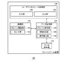
- FIG. 2 is a functional block diagram of the crane game device 100.
- Each component of the crane game device 100 includes a CPU (Central Processing Unit), a computing unit such as various coprocessors, a storage device such as a memory and a storage device, hardware including a wired or wireless communication line connecting them, and a storage device. It is stored in and realized by software that supplies processing instructions to the arithmetic unit.
- a computer program may be composed of a device driver, an operating system, various application programs located on the upper layers thereof, and a library that provides common functions to these programs.
- Each block described below shows a block for each function, not a configuration for each hardware.
- the crane game device 100 includes a user interface processing unit 140, a mechanism unit 142, a data processing unit 144, and a data storage unit 146.
- the user interface processing unit 140 accepts operations from the player via various input devices, and is in charge of processing related to the user interface such as image display and audio output.
- the mechanism unit 142 drives various mechanisms such as the crane 108.
- the data storage unit 146 stores various data.
- the data processing unit 144 executes various processes based on the input from the user interface processing unit 140 and the data stored in the data storage unit 146.
- the data processing unit 144 also functions as an interface for the mechanism unit 142, the user interface processing unit 140, and the data storage unit 146.
- the user interface processing unit 140 includes an input unit 148 and an output unit 150 that outputs various information such as images and sounds.
- the input unit 148 receives the setting input from the operator via the setting display unit 120. Further, the input unit 148 receives an operation input from the player via the operation unit 118.
- the crane game device 100 has a setting mode and a play mode. In the setting mode, the operator makes various settings described later. The delivery of prizes or the attachment of the display bar 134 is also performed during the setting mode. In the play mode, the player operates the operation unit 118 to play the crane game.
- the mechanism unit 142 includes the crane drive unit 130 and the sensor group 152. As described above, the crane driving unit 130 moves the crane 108 and grips and releases the arm 126.
- the sensor group 152 corresponds to an optical sensor (described later) at the drop port 114, an optical sensor that detects the position of the plate (described later) in the mounting area 112, and the like.
- the data processing unit 144 includes a crane control unit 154, a movement determination unit 156, and a boundary detection unit 158.
- the crane control unit 154 instructs the crane 108 to move, grip, and release according to the operation instruction by the operation unit 118.
- the movement determination unit 156 determines whether the prize has fallen into the drop port 114, in other words, the success or failure of the crane game.
- the boundary detection unit 158 detects the boundary position between the drop port 114 and the placement area 112. The details of the boundary position detection method will be described later.
- the data storage unit 146 stores information such as a crane game game program, a crane game setting, and a game play result (payout rate).
- a crane game game program such as a crane game program, a crane game setting, and a game play result (payout rate).
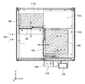
- FIG. 3 is a top view of the prize mounting table 106.
- the prize mounting table 106 includes the mounting area 112 and the drop port 114.
- the mounting area 112 further includes a first mounting area 112a located on the Y-axis positive direction side (back side) of the drop port 114, a second mounting area 112b located on the X-axis positive direction side (right side), and a drop. It is composed of a third mounting area 112c located diagonally behind the mouth 114.
- the upper part of the first mounting area 112a is covered with the Y plate 160 (first plate).
- the upper part of the second mounting area 112b is covered with the X plate 162 (second plate).
- the upper surface of the Y plate 160 in the first mounting region 112a, the upper surface of the X plate 162 in the second mounting region 112b, and the upper surface of the third mounting region 112c are formed so as to be flush with each other.
- the Y plate 160 (covering the first mounting area 112a), the X plate 162 (covering the second mounting area 112b), and the third mounting area 112c (exposed) have steps on their respective upper surfaces. It is configured not to.
- the X plate 162 can move horizontally in the negative direction of the X axis. By horizontally moving the X plate 162, the operator can reduce the size (width) of the drop port 114.
- a shielding plate 128 is fixed to the end of the X plate 162. As the X plate 162 moves, the shielding plate 128 also moves in the direction of narrowing the drop port 114.
- the second mounting area 112b is provided with a position detection sensor 164 (optical sensor) for detecting the amount of movement of the X plate 162, in other words, the position of the X plate 162. The details of the detection method will be described later in relation to FIGS. 4 and later.
- the Y plate 160 can move horizontally in the negative direction of the Y axis. By horizontally moving the Y plate 160, the operator can reduce the size (vertical width) of the drop port 114. Since the shielding plate 128 is also fixed to the end of the Y plate 160, the shielding plate 128 also moves in the direction of narrowing the drop port 114 as the Y plate 160 moves. Although not shown, the amount of movement of the Y plate 160 can also be detected by the same method as that of the X plate 162.
- the Y plate 160 and the X plate 162 cannot be moved at the same time.
- the Y plate 160 is moved in the negative direction on the Y axis to narrow the drop port 114 in the Y direction
- the X plate 162 cannot be moved.
- the Y plate 160 cannot be moved. This is because the upper surfaces of the Y plate 160 and the X plate 162 are made to have the same height, instead of intersecting the Y plate 160 and the X plate 162 with a step.
- the prize or the arm 126 may be caught in the step and the play may be hindered.
- the Y plate 160, the X plate 162, and the third mounting region 112c are formed so as to be flush with each other.
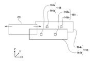
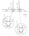
- FIG. 4 is a configuration diagram of the position detection sensor 164.
- a detection plate 170 projecting in the negative direction of the Z axis is fixed to the lower surface of the X plate 162.
- the position detection sensor 164 includes a transmission plate 164a and a reception plate 164b.
- the transmitting plate 164a and the receiving plate 164b project in the positive direction of the Z axis on the upper surface of the second mounting region 112b.
- the detection plate 170 moves between the transmission plate 164a and the reception plate 164b as the X plate 162 moves in the X direction.
- the position detection sensor 164 includes a first optical sensor 166 and a second optical sensor 168.
- the first optical sensor 166 has a first transmitter 166a that emits optical signals such as infrared rays and laser light on the transmitter plate 164a, and a first receiver 166b that receives optical signals from the first transmitter 166a on the receiver plate 164b.
- the second optical sensor 168 includes a second oscillator 168a that emits an optical signal on the transmitting plate 164a and a second receiver 168b that receives an optical signal from the second oscillator 168a on the receiving plate 164b.
- the amount of movement m of the X plate 162 in the negative direction of the X axis is set in three stages.
- the X coordinate of the boundary position of the tip of the X plate 162 (hereinafter referred to as "X boundary coordinate") is registered.
- the boundary detection unit 158 detects the X boundary coordinates by measuring the movement amount m with the position detection sensor 164.
- both the first optical sensor 166 and the second optical sensor 168 are shielded by the detection plate 170, so that both the first receiver 166b and the second receiver 168b are both. Does not detect optical signals.
- the boundary detection unit 158 determines that the movement amount m of the X plate 162 is zero when the light detection signal is not received from both the first receiver 166b and the second receiver 168b.
- only the first optical sensor 166 is shielded by the detection plate 170, so that the first receiver 166b does not detect the optical signal and the second receiver 168b does not detect the optical signal. Is detected.
- the boundary detection unit 158 receives the light detection signal only from the second receiver 168b, the boundary detection unit 158 determines that the movement amount m of the X plate 162 is the intermediate value X1.
- neither the first optical sensor 166 nor the second optical sensor 168 is shielded by the detection plate 170, so that both the first receiver 166b and the second receiver 168b are light.
- Detect the signal the boundary detection unit 158 receives the light detection signal from both the first receiver 166b and the second receiver 168b
- the boundary detection unit 158 determines that the movement amount m of the X plate 162 is the maximum value X2.
- the amount n of movement of the Y plate 160 in the negative direction of the Y axis can be detected in the same manner.
- Y boundary coordinate the Y coordinate of the boundary position of the tip of the Y plate 160 (hereinafter referred to as "Y boundary coordinate" is registered.
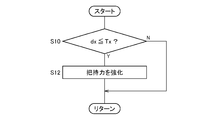
- FIG. 6 is a flowchart showing the gripping force adjusting process of the arm 126.
- the crane control unit 154 increases the gripping force of the arm 126 when the crane 108 approaches the drop port 114.
- the crane 108 grabs the prize, the player expects the prize to be carried to the drop port 114 without falling in the middle. Therefore, in the present embodiment, when the distance dx between the X coordinate of the crane 108 (hereinafter referred to as “X crane coordinate”) and the X boundary coordinate becomes equal to or less than a predetermined threshold value Tx (Y in S10), the crane control unit 154 increases the gripping force of the arm 126 (S12). When the distance dx is larger than the threshold value Tx (N in S10), the gripping force is not changed.
- the boundary detection unit 158 specifies the movement amount m of the X plate 162 in advance by the position detection sensor 164.
- the boundary detection unit 158 specifies the X boundary coordinates depending on which of the three stages of movement amount m.
- the crane control unit 154 calculates the distance dx based on the X boundary coordinates and the X crane coordinates.
- the movement determination unit 156 may detect the X crane coordinates by a rotary encoder (not shown) mounted on the crane 108. Not limited to this, the movement determination unit 156 may calculate the X crane coordinates by a known technique such as laser measurement or image recognition by a camera.
- the Y coordinate may be determined in the same manner.
- the crane control unit 154 increases the gripping force of the arm 126 even when the distance dy between the Y boundary coordinates and the Y coordinates of the crane 108 (hereinafter referred to as "Y crane coordinates") is equal to or less than a predetermined threshold value Ty. May be good.
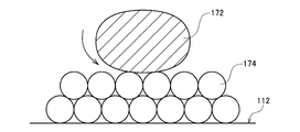
- FIG. 7 is a schematic view showing a placement state of the prize 172 in the placement area 112.
- a plurality of color balls 174 are spread over the mounting area 112.
- Various prizes 172 such as stuffed animals are placed on the layer of the color balls 174.
- the color ball 174 is an elastic vinyl ball.
- One of the purposes of laying out the color balls 174 is to enhance the decorativeness of the play space S.
- the arm 126 directly touches the mounting area 112, the arm 126 or the mounting area 112 may be scratched. Therefore, the mounting area 112 and the arm 126 are formed by forming a layer of the color balls 174. Prevent contact.
- the layer of the color ball 174 creates a gap under the prize 172, it becomes easy to insert the arm 126 into the lower part of the prize 172. Therefore, by forming the layer of the color ball 174, the arm 126 can easily grasp the prize 172 firmly.
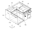
- FIG. 8 is a perspective view of the base 102.
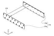
- FIG. 9 is a perspective view of the price sensor 176.
- a price sensor 176 is arranged on the inner wall surface of the drop port 114.
- the price sensor 176 includes a first detection plate 176a and a second detection plate 176b that face each other.
- a total of 30 optical sensors 178 are arranged on the first detection plate 176a and the second detection plate 176b, 15 each.
- optical sensors 178 are arranged on the upper stage of the first detection plate 176a and seven optical sensors 178 are arranged on the lower stage, and the same applies to the second detection plate 176b. Fifteen optical sensors 178 arranged on each of the first detection plate 176a and the second detection plate 176b are arranged so as to face each other, forming a total of 15 pairs. Similar to the position detection sensor 164, one optical sensor 178 functions as a photodetector and the other optical sensor 178 facing it functions as an optical receiver. An optical signal is constantly transmitted from one of the two paired optical sensors 178 to the other.
- the movement determination unit 156 receives an optical detection signal from each pair of optical sensors 178.
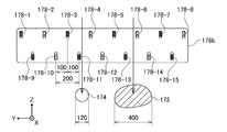
- FIG. 10 is a schematic diagram for explaining a method of detecting the prize 172 and the color ball 174.
- the second detection version 176b eight optical sensors 178 from the optical sensor 178-1 to the optical sensor 178-8 are arranged in the upper stage, and seven optical sensors 178 from the optical sensor 178-9 to the optical sensor 178-15 are arranged. Is placed in the lower row. The upper and lower optical sensors are offset by the Y coordinate of each 178 installation position.
- the distance between the upper optical sensor 178 (for example, the optical sensor 178-3) and the lower optical sensor 178 (for example, the optical sensor 178-11) next to it in the Y direction is 100 mm. Further, it is assumed that the distance between the lower optical sensor 178 (for example, the optical sensor 178-10) and the lower optical sensor 178 (for example, the optical sensor 178-11) adjacent thereto in the Y direction is 200 mm. It is assumed that the diameter of the color ball 174 in this embodiment is 120 mm. Further, it is assumed that the width of the prize 172 is at least 400 mm or more.
- the optical signal of the lower optical sensor 178-11 is temporarily cut off (hereinafter referred to as "passing reaction").
- passing reaction the optical signal of the lower optical sensor 178-11
- the diameter of the color ball 174 is 120 mm, and the distance from the optical sensor 178-11 to the optical sensor 178-12 next to it is 200 mm. Therefore, when the color ball 174 is dropped, the passing reaction is not detected from the optical sensors other than the optical sensor 178-11 in the lower stage. The same applies to the upper row. Therefore, in the movement determination unit 156, when the passing reaction is detected by any of the optical sensors 178 and the number of passing reactions in the upper stage is 1 or less and the number of passing reactions in the lower stage is 1 or less, the color ball 174 has fallen. Is determined.
- a passing reaction is detected by one or more optical sensors 178.
- the passing reaction is detected by the upper optical sensor 178-6 and the lower optical sensor 178-13 and the optical sensor 178-14. Since the prize 172 is larger than the color ball 174, a passing reaction is detected by two or more adjacent optical sensors 178 in the same stage. Therefore, the movement determination unit 156 determines that the prize 172 has fallen when the passing reaction is generated by the upper and lower optical sensors 178 and the number of passing reactions in either the upper or lower stage is 2 or more.
- FIG. 11 is a first exploded perspective view of the crane game device 100 showing a state when the display bar 134 is installed.
- the display bar 134 is a metal rod-shaped member whose one end is bent at a right angle.
- the operator first installs the display bar 134 on the first support column 180 at the back of the crane game device 100 (on the positive direction side of the X axis).
- a plurality of lateral grooves 182 are formed in the first support column 180.
- the operator inserts the insertion portion 184 at the tip of the display bar 134 into the lateral groove 182 of the first support column 180 from the horizontal direction. Details of the fitting structure of the insertion portion 184 and the lateral groove 182 will be described later in relation to FIG.
- FIG. 12 is a second exploded perspective view of the crane game device 100 showing a state when the display bar 134 is installed. Also in FIG. 12, some members such as the door 110 are deleted and drawn. A plurality of insertion holes 188 are formed in advance in the second support column 186 on the front side (X-axis negative direction side) of the back surface of the crane game device 100. The position of the insertion hole 188 is the same height as the position of the lateral groove 182 of the first support column 180.
- the operator inserts the support rod 190 into an arbitrary insertion hole 188.
- the operator inserts one end (back side) of the display bar 134 into the lateral groove 182 of the first support column 180, and then hooks the hook 192 at the other end (front side) of the display bar 134 on the support rod 190 to lock the display bar 134.
- the operator inserts one end of the display bar 134 into the first support column 180, and then hooks the other end of the display bar 134 on the support rod 190 to attach the display bar 134 to the second support column 186 and the first support column 180. Fix it.
- the work of installing the display bar 134 on the first column 180 has been a heavy burden.
- the operator opens the door in front of the prize outlet 116 and the glass door 110 of the prize storage unit 104 to enter the prize drop space (the space where the drop port 114 is formed).
- the prize drop space is located on the left side (X-axis negative direction) of the housing, so the right back of the housing (X-axis positive direction and) Many operators cannot reach the first column 180 located in the positive direction of the Y-axis).
- the hook 192 is hooked on the support rod 190 and locked on the front side, so that the display bar 134 can be easily installed.
- FIG. 13 is an enlarged view of the fitting portion between the display bar 134 and the first support column 180.
- a plurality of lateral grooves 182 are formed in the first support column 180.
- the operator inserts a relatively small-diameter insertion portion 184 at the tip of the display bar 134 into the lateral groove 182 from the horizontal direction.
- a plate-shaped first support member 208 is formed on the front side (Y-axis negative direction side), and a plate-shaped second support member 210 is also formed on the back side (Y-axis positive direction side). Will be done.
- the first support member 208 is formed so as to be higher (relatively protruding) in the Z-axis direction than the second support member 210. Further, on the upper side of the lateral groove 182, the second support member 210 is formed so as to be lower (relatively protruding) than the first support member 208 in the Z-axis direction.
- the operator inserts the display bar 134 into the lateral groove 182 with the display bar 134 tilted slightly upward. Can be done.
- the back side of the insertion portion 184 is regulated by the relatively protruding second support member 210, and the front side is regulated by the relatively protruding first support member 208. Will be done.
- the regulating member 212 having a relatively large diameter is provided on the back side of the insertion portion 184, even if the display bar 134 is pulled in the front direction (Y-axis negative direction), the regulating member 210 is provided by the second support member 210. 212 is regulated. Due to such a structure, the display bar 134 is more difficult to come off.
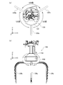
- FIG. 14A is a top view of the crane 108 at the time of initial setting.
- FIG. 14B is a front view of the crane 108 at the time of initial setting.
- the crane 108 has three arms 126 (first arm 126a, second arm 126b and third arm 126c).
- the first arm 126a, the second arm 126b, and the third arm 126c are each deviated by 120 degrees.
- the first arm 126a is usually provided at a position facing the player (see also FIG. 1).
- a design cover 132 is installed on the first arm 126a.
- a logo plate 194 is fixed to the design cover 132.
- the logo plate 194 functions as an advertisement or decoration for attracting the player to the crane game device 100.
- FIG. 15A is a top view of the crane 108 when rotated by 30 degrees.
- FIG. 15B is a front view of the crane 108 when rotated by 30 degrees.
- the layout of the plurality of prizes 172 also changes. For example, if one prize 172 is near the drop port 114, it is considered that the player operates the crane 108 with the prize 172 as a target (acquisition target).
- the arm 126 may hit the shield plate 128 near the boundary of the drop port 114, making it difficult to grasp the prize 172. Therefore, usually, the operator may adjust the horizontal rotation angle of the crane 108 so that the arm 126 does not hit the shielding plate 128 while observing the arrangement state of the prize 172. Further, depending on the orientation of the prize 172, it may be easier to obtain the prize 172 by changing the position of the arm 126. The operator may rotate the crane 108 horizontally to make it easier to obtain the prize 172 in order to motivate the customer to play.
- the crane 108 is rotated 30 degrees clockwise when viewed from above.
- the design cover 132 and the logo plate 194 also face to the left when viewed from the player.
- the horizontal rotation angles of the cranes 108 often do not match.
- a large number of logo plates 194 are oriented in different directions, which may spoil the aesthetic appearance of the amusement facility.
- the logo plate 194 which should originally function as an advertisement when starting the crane game, is not facing the front (player side), some players may feel uncomfortable.
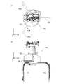
- FIG. 16A is a top view of the crane 108 when the design cover 132 is adjusted.
- FIG. 16B is a front view of the crane 108 when the design cover 132 is adjusted.
- the design cover 132 is configured to be horizontally rotatable independently of the crane 108 by the structure described later. The operator can adjust the logo plate 194 to face the front (player side) by rotating the crane 108 body clockwise and then rotating only the design cover 132 counterclockwise.
- FIG. 17 is an exploded perspective view of the crane 108 around the design cover 132.
- FIG. 18 is a side sectional view of the crane 108 around the design cover 132.
- a guide groove 204 is formed in the cover member 200 which is the outer wall of the crane 108, and the design cover holder 196 is sandwiched between the guide groove 204 and the lock plate 198.
- the lock plate 198 is fixed to the cover member 200 by screws.
- the design cover holder 196 can rotate horizontally along the guide groove 204 while being guided by the lock plate 198 in the horizontal plane (XY plane).
- the design cover 132 (logo plate 194) is fixed to the rotatable design cover holder 196 with screws.
- the operator holds the crane 108 with one hand and grabs and rotates the design cover 132 with the other hand to rotate the design cover 132 as shown in FIGS. 16A and 16B.
- the orientation can be adjusted manually.
- FIG. 19 is a side sectional view of the storage box 206.
- FIG. 19 shows a cross section when the crane game device 100 is cut along the line AA of FIG. 1 and the line-of-sight direction is the positive direction of the X-axis.
- the storage box 206 is formed in the lower part of the first mounting area 112a.
- the storage box 206 forms a space for storing equipment such as a support rod 190 (see FIG. 12), a color ball 174, and various screws and tools.
- the lower surface of the storage box 206 is inclined.
- the tilt angle is 10 to 30 degrees, more preferably 12 to 20 degrees.
- the operator opens the door 110 of the prize storage unit 104 and the front door of the prize outlet 116, enters the fall port 114 (premium fall space), and uses the storage box 206. Since the lower surface of the storage box 206 is tilted, the operator can easily see the storage box 206 to the back without crouching excessively. In other words, by inclining the lower surface of the storage box 206 so as to approach the line-of-sight direction (looking down direction) of the operator during work, the operator can relatively easily check the depth of the storage box 206. Further, the storage size of the storage box 206 can be increased by providing the inclination angle.
- the crane game device 100 has been described above based on the embodiment.
- the gripping force of the arm 126 is strengthened. Therefore, when the crane 108 approaches the drop port 114, the possibility that the crane 108 will drop the prize 172 is reduced.
- the gripping force of the arm 126 becomes stronger, so that the player can further increase the expectation for the prize acquisition.
- the prize 172 is brought close to the drop opening 114 by playing a plurality of times, the possibility of acquiring the prize is increased, so that the player's motivation to continue the game is easily increased.
- the operator can freely change the shape of the drop port 114 by horizontally moving the Y plate 160 or the X plate 162.
- the "shape" here may be any one or more of the opening size (area) of the drop port 114, the X boundary coordinates, and the Y boundary coordinates.
- the X boundary coordinates and the Y boundary coordinates when the X plate 162 or the like is horizontally moved are automatically detected by the position detection sensor 164 and the boundary detection unit 158.
- the crane control unit 154 can appropriately change the strengthening timing of the gripping force of the arm 126 based on the detection result. In this way, the operator can automatically and appropriately adjust the gripping force of the arm 126 by simply moving the X plate 162 or the like without making other settings.
- the mounting area 112 is covered with colorful colored balls 174, and the prize 172 is placed on the layer of the colored balls 174. Therefore, it is conceivable that the color ball 174, instead of the prize 172, falls into the drop port 114.
- the price sensor 176 formed on the inner wall of the drop port 114 includes a plurality of optical sensors 178. Depending on the number of passing reactions of the optical sensor 178, the movement determination unit 156 can determine in a simple configuration whether the prize 172 or the color ball 174 has fallen.
- the crane game device 100 has a structure in which the display bar 134 can be easily fitted into the first support column 180 on the back side, which is particularly difficult to attach when the display bar 134 is attached.
- the operator can stabilize the display bar 134 in the first support column 180 by inserting the display bar 134 into the lateral groove 182 formed in the first support column 180 from the side. After inserting the display bar 134 into the first support column 180, the operator can easily fix the display bar 134 by hooking the hook 192 of the display bar 134 on the support rod 190. Therefore, the display bar 134 can be easily installed even when the first support column 180 cannot be reached.
- the crane 108 in this embodiment can rotate horizontally depending on the situation of the crane game. Since the design cover 132 can be rotated horizontally relative to the crane 108, the design cover 132 (logo plate 194) can be adjusted to face the player regardless of the orientation of the crane 108. In particular, when arranging a plurality of crane game devices 100, if the logo plates 194 of all the crane game devices 100 are oriented in the same direction, not only the visibility of the logo plates 194 is improved, but also a sense of unity in the amusement facility is achieved. It is also effective for making.
- the storage box 206 is further formed in a part of the base 102.
- the workability of the operator can be improved. Further, this can effectively expand the storage space of the storage box 206.
- the present invention is not limited to the above-described embodiment or modification, and the components can be modified and embodied within a range that does not deviate from the gist.
- Various inventions may be formed by appropriately combining a plurality of components disclosed in the above embodiments and modifications.
- some components may be deleted from all the components shown in the above embodiments and modifications.
- the distance dx is calculated based on the X boundary coordinates and the X crane coordinates, and when the distance dx is equal to or less than the threshold value Tx, the crane control unit 154 strengthens the gripping force of the arm 126.
- the crane control unit 154 may set the gripping force of the arm 126 to "normal” regardless of the X crane coordinates.
- the crane control unit 154 sets the gripping force of the arm 126 to "strong (for example, 130% of the normal time)" regardless of the X crane coordinates. It may be set.
- the gripping force is weak, and when the opening size of the fall port 114 is small, the gripping force is set large. Can be stabilized. The same applies when adjusting the opening size of the drop port 114 with the Y plate 160.
- the difficulty level may be greatly changed in conjunction with the opening size by weakening the gripping force when the opening size of the falling port 114 is small and increasing the gripping force when the opening size of the falling port 114 is large.
- the gripping force may be adjusted according to the opening size of the drop port 114, not limited to the distance between the drop port 114 and the crane 108.
- the X boundary coordinates and the Y boundary coordinates have been described as being detected by the boundary detection unit 158 based on the movement amount of the X plate 162 and the Y plate 160.
- the operator may horizontally move the X plate 162 or the like and then input the X boundary coordinates or the like as setting information via the setting display unit 120.
- the boundary detection unit 158 may specify the X boundary coordinates of the drop port 114 based on this setting information.
- the gripping force when the crane 108 approaches the X boundary coordinates, the gripping force is strengthened to raise the expectation of the player to acquire the prize.
- the gripping force may be weakened when the crane 108 approaches the X boundary coordinates.
- the gripping force of the arm 126 is set to "strong" at the initial stage, and when the distance dx between the X boundary coordinates and the X crane coordinates becomes equal to or less than the threshold value Tx, the crane control unit 154 sets the gripping force of the arm 126. It may be set to "medium” or "weak". According to such a control method, since the arm 126 has a strong initial gripping force, it is less likely that the prize 172 will fail to be lifted.
- the difficulty level of the crane game is excessively lowered, and the expectation of obtaining a prize is excessively increased. Can be prevented.
- the disappointment caused by the arm 126 not being able to grab the prize 172 is less likely to occur at an early stage, and the crane 108 is tense when carrying the prize 172. It makes it easier for more players to experience the feeling. The same applies to the distance dy between the Y boundary coordinates and the Y crane coordinates.
- the crane control unit 154 when the distance dx is equal to or less than a predetermined threshold value Tx, the crane control unit 154 weakens the gripping force of the arm 126.
- the crane control unit 154 may gradually (continuously) weaken the gripping force of the arm 126 as the distance dx decreases.
- the gripping force of the arm 126 may be gradually increased as the distance dx becomes smaller. The same applies to the distance dy.
- the gripping force of the arm 126 may be discontinuously changed according to the distance dx.
- the gripping force of the arm 126 when the distance dx is larger than the threshold value T1 (long distance), the gripping force of the arm 126 is set to "normal", and when the distance dx is equal to or less than the threshold value T1 and larger than the threshold value T2 ( ⁇ T1) (medium distance).
- the gripping force of the arm 126 may be set to "weak", and when the distance dx is equal to or less than the threshold value T2 (short distance), the gripping force of the arm 126 may be set to "strong".
- the crane control unit 154 may control the gripping force of the arm 126 according to the shape of the drop port 114, the distance dx, the distance dy, and the operating time of the crane 108.
- the timer may be started at the start of the crane game, and as time elapses, the crane control unit 154 may weaken or strengthen the gripping force of the arm 126.
- the game components other than the gripping force of the arm 126 may be controlled based on the shape of the drop port 114, the distance between the drop port 114 and the crane 108, and the like. For example, when the distance dx becomes equal to or less than a predetermined threshold value, the output unit 150 may change the BGM (background music) or change the volume of the BGM. Further, when the monitor is installed in the crane game device 100, the output unit 150 may change the image to be displayed on the monitor according to the distance dx.
- BGM background music
- the output unit 150 may change the image to be displayed on the monitor according to the distance dx.
- the crane control unit 154 may change the moving speed of the crane 108 when the distance dx becomes equal to or less than a predetermined threshold value. For example, the crane control unit 154 reduces the moving speed of the crane 108 before the crane 108 grabs the prize 172 to make it easier to grab the prize 172, and increases the moving speed of the crane 108 after the crane 108 grabs the prize 172. The tension of the game may be increased by making the prize 172 easy to drop.
- the design cover 132 may mount a monitor instead of the logo plate 194.
- the output unit 150 may change the image to be displayed on the monitor of the design cover 132 according to the distance dx.
- the prize 172 and the color ball 174 are discriminated by the price sensor 176.
- a plurality of types of prizes 172 having different sizes may be placed in the mounting area 112.
- the movement determination unit 156 may determine which of the plurality of types of prizes 172 the prize 172 has fallen into the drop port 114.
- the price sensor 176 has been described as having a plurality of optical sensors 178 arranged in two rows, an upper row and a lower row, the plurality of optical sensors 178 may be arranged in one row or three or more rows. .. The interval between the optical sensors 178 may be adjusted so that the number of passing reactions of the optical sensor 178 differs according to the size of the falling object.
- the crane game device 100 can also be applied to a so-called net catcher.
- the net catcher is a crane game in which a player operates a crane 108 of a crane game device 100 at a remote location by transmitting operation information while confirming the state of prize acquisition on a PC in real time by a camera image. The prize acquired by the player is mailed to the player.
- the prize placing table 106 is provided with a first area for placing the prize 172 and a second area for moving the prize 172.
- the second region may be formed as a drop port 114 or may be a simple panel.
- Crane game device 102 base, 104 prize storage, 106 prize mounting table, 108 crane, 110 door, 112 mounting area, 112a 1st mounting area, 112b 2nd mounting area, 112c 3rd mounting area , 114 drop port, 116 prize outlet, 118 operation unit, 120 setting display unit, 122 operation rod, 124 grip button, 126 arm, 126a 1st arm, 126b 2nd arm, 126c 3rd arm, 128 shielding plate, 130 Crane drive unit, 132 design cover, 134 display bar, 140 user interface processing unit, 142 mechanism unit, 144 data processing unit, 146 data storage unit, 148 input unit, 150 output unit, 152 sensor group, 154 crane control unit, 156 Movement judgment unit, 158 boundary detection unit, 160 Y plate, 162 X plate, 164 position detection sensor, 164a transmitter plate, 164b receiver plate, 166 first optical sensor, 166a first transmitter, 166b first receiver, 168th 2 optical sensor, 168a second oscillator
Landscapes
- Engineering & Computer Science (AREA)
- Multimedia (AREA)
- Physics & Mathematics (AREA)
- General Physics & Mathematics (AREA)
- Pinball Game Machines (AREA)
- Toys (AREA)
Abstract
クレーンゲーム装置においてクレーンが落下口に近づいたときの興趣をいっそう高める。 クレーンゲーム装置100は、景品が載置される載置領域112と落下口114を有する。プレイヤは、操作部118を操作してクレーン108を移動させる。落下口114のサイズは可変である。クレーンゲーム装置100は、落下口114と載置領域112の境界位置を検出し、クレーン108が境界位置に近づいたとき、アーム126の把持力を変化させる。
Description
本発明は、景品等の物品を移動させて獲得する物品取得ゲームに関する。
多くのゲームセンターには、クレーンゲーム装置(物品取得ゲーム装置)が設置されている。クレーンゲーム装置の筐体内にはステージ(ゲームフィールド)が設けられ、ぬいぐるみやお菓子などの景品(物品)が載置される。プレイヤは、操作桿あるいは各種ボタンを駆使してクレーンを操作する。クレーンで景品を掴み、落下口に景品を移動できれば、プレイヤは景品を獲得できる(特許文献1参照)。
一般的には、クレーンで景品を掴んで落下口近くまでこれを運んだとき、いいかえれば、景品の取得可否が決まる瞬間に近づいたとき、プレイヤの期待感がもっとも高まりやすい。
本発明は、クレーンゲーム特有の興趣について再検討した上で完成された発明であり、その主たる目的は、クレーンゲーム装置においてクレーンが落下口(景品の移動目的地)に近づいたときの興趣をいっそう深めるための技術、を提供することにある。
本発明の物品取得ゲーム装置は、プレイ空間に設けられ、獲得対象となる物品が載置される第1領域と物品の移動先となる第2領域とを有するゲームフィールドと、物品を把持するクレーンと、プレイヤからの操作を受け付ける操作部と、操作にしたがって、クレーンを駆動するクレーン制御部と、第2領域の境界位置を検出する境界検出部と、を備える。
クレーン制御部は、第2領域の境界位置に応じて、クレーンの把持力を変化させる。
クレーン制御部は、第2領域の境界位置に応じて、クレーンの把持力を変化させる。
本発明の物品取得ゲーム装置は、プレイ空間に設けられ、獲得対象となる物品が載置される第1領域と物品の移動先となる第2領域とを有するゲームフィールドと、物品を把持するクレーンと、プレイヤからの操作を受け付ける操作部と、操作にしたがって、クレーンを駆動するクレーン制御部と、を備える。 第2領域は、その形状を変更可能に構成される。クレーン制御部は、第2領域の形状に応じて、クレーンの把持力を変化させる。
本発明によれば、物品取得ゲーム装置の興趣を深めやすくなる。
図1は、クレーンゲーム装置100の斜視図である。 クレーンゲーム装置100は、一般的には、遊園地やゲームセンターなどの遊戯施設に設置される。図1に示すように、プレイヤから見たときのクレーンゲーム装置100の左右方向をX方向、前後方向をY方向、上下方向をZ方向として説明する。
クレーンゲーム装置100は、直方体形状の基台102と、基台102上に設けられた箱型の景品収容部104を備える。景品収容部104の内方にプレイ空間Sが形成され、景品載置台106(ゲームフィールド)が設けられる。景品載置台106上には、ぬいぐるみや雑貨等の景品のほか、景品載置台106を装飾するためのカラーボールが配置される(後述)。景品載置台106の上方にはクレーン108が設けられる。クレーン108は、プレイ空間Sの前後左右および上下に移動でき、景品を把持/解放する。
景品収容部104は、その前面および左右側面が透明なガラス張りとされている。外部からの景品の視認性が考慮されたものである。景品収容部104の天井面には、景品載置台106を上方から撮像するカメラが設置されてもよい。景品収容部104の前面にはガラス製の扉110が設けられ、オペレータ(店員)は扉110を開いて景品を景品収容部104内に配置できる。
景品載置台106は、載置領域112(第1領域)と落下口114(第2領域)に区画される。載置領域112に景品が載置され、プレイヤは景品を載置領域112から落下口114に運ぶことができれば、景品を取得できる。載置領域112と落下口114の間は遮蔽板128が設置される。遮蔽板128は、載置領域112にある景品あるいはカラーボールが落下口114に転げ落ちるのを防ぐ。
基台102の前面には、落下口114から落下した景品を取り出すための景品取出口116が形成される。
基台102の前面側には操作部118および設定表示部120が設けられる。ゲーム開始に際し、プレイヤは、コイン投入口にコインを投入するか、ICカードリーダに電子マネーがチャージされたICカードをタッチする。以下、クレーンゲーム装置100において、操作部118等が設置される面、いいかえれば、プレイヤが位置する側の面を「前面」とよび、プレイヤから見て奥側(Y軸正方向側)にある面を「背面」とよぶ。
操作部118は、プレイヤがクレーン108を前後左右に移動させてその降下地点を決めるための操作桿122と、クレーン108を降下させて景品を把持させるための把持ボタン124を含む。
設定表示部120にはタッチパネルが設置される。設定表示部120は、オペレータ(店員)がゲームの設定情報を入力する「設定入力部」として機能するとともに、操作部118の操作方法やゲーム結果など、ゲームに関する情報を表示させる「情報表示部」としても機能する。クレーンゲーム装置100は、そのほかにもスピーカ(不図示)や外部接続端子等を備える。
クレーン108は、景品を把持および解放可能な3本のアーム126を有する。クレーン108はアーム126を開閉駆動するモータを含む。クレーン108は、アーム126を開閉させることによって、景品を把持および解放する。
クレーン108は、景品収容部104の上部に設置された図示略のガイドレールに沿って移動可能であり、クレーン駆動部130(後述)により駆動される。クレーン駆動部130は、クレーン108を横方向(X方向)および縦方向(Y方向)に駆動する移動機構と、上下方向(Z方向)に駆動する昇降機構を含む。移動機構は、X方向モータおよびY方向モータを含む。昇降機構は、Z方向モータを含む。クレーン駆動部130により、クレーン108をプレイ空間Sの任意の位置に移動させることができる。
本実施形態におけるクレーン108は、3つのアーム126を有するいわゆる「トリプルキャッチャー型」である。プレイヤは、制限時間以内であれば操作桿122によりクレーン108を前後左右に自由に動かすことができる。プレイヤは、景品の上方にクレーン108を移動させたあと、把持ボタン124を押下する。把持ボタン124が押下されると、クレーン108は下降する。クレーン108は所定距離を下降すると自動的にアーム126を閉鎖方向に移動させる(以下、「把持」あるいは「把持動作」とよぶ)。このとき、クレーン108は降下地点にある比較的大きな景品をアーム126により掴むことができる。なお、クレーン108の下降中に再度把持ボタン124を押下すれば、押下時点においてアーム126に把持動作させることもできる。
把持動作を維持したまま、クレーン108は上昇し、その後、落下口114に向けて自動的に移動する。クレーン108は、落下口114の上でアーム126を解放方向に移動させる(以下、「解放」あるいは「解放動作」とよぶ)。景品をしっかりと把持できていれば、景品は落下口114までクレーン108によって運ばれ、落下口114の上から落とされる(クレーンゲームの成功)。一方、アーム126が景品をしっかり把持できていなかったときには、クレーン108が落下口114の直上に到達する前に、クレーン108から景品が落下してしまう(クレーンゲームの失敗)。
なお、オペレータは、クレーン108を水平回転(Z軸を中心とした回転)させることもできる。図1に示すように、3つのアーム126のうちの1つがプレイヤ側にくる状態がホームポジションであるが、オペレータは景品の配置状況に鑑みて、クレーン108の水平回転角を調整できる。クレーン108の前面には、デザインカバー132が設置される。本実施形態におけるデザインカバー132には、製品名を示すロゴ(広告情報)が記載される。クレーン108の水平回転に対応してデザインカバー132の方向も調整可能であるが、詳細は図14等に関連して後述する。
落下口114の内部には複数の光センサが設置される。この光センサにより景品の落下口114への落下(以下、単に「景品取得」ともよぶ)を検出する。また、これらの光センサは、カラーボールおよび景品のいずれが落下したかを区別できるように構成されているが詳細は図8等に関連して後述する。
景品収容部104の背面には、1以上のディスプレイバー134が設置される。ディスプレイバー134は、X方向に延伸する金属棒材であり、ここに展示用の景品を挟むことができる。オペレータは、扉110を開けて落下口114に入り、ディスプレイバー134を背面に設置する。ディスプレイバー134の数および高さは任意である。ディスプレイバー134の設置方法については、図11以降に関連して後述する。
落下口114の奥にはカラーボールなどの備品を収納するための収納ボックスが設けられる。この収納ボックスについては図19に関連して後に詳述する。
図2は、クレーンゲーム装置100の機能ブロック図である。 クレーンゲーム装置100の各構成要素は、CPU(Central Processing Unit)および各種コプロセッサなどの演算器、メモリやストレージといった記憶装置、それらを連結する有線または無線の通信線を含むハードウェアと、記憶装置に格納され、演算器に処理命令を供給するソフトウェアによって実現される。コンピュータプログラムは、デバイスドライバ、オペレーティングシステム、それらの上位層に位置する各種アプリケーションプログラム、また、これらのプログラムに共通機能を提供するライブラリによって構成されてもよい。以下に説明する各ブロックは、ハードウェア単位の構成ではなく、機能単位のブロックを示している。
クレーンゲーム装置100は、ユーザインタフェース処理部140、機構部142、データ処理部144およびデータ格納部146を含む。 ユーザインタフェース処理部140は、各種の入力デバイスを介してプレイヤからの操作を受け付けるほか、画像表示や音声出力など、ユーザインタフェースに関する処理を担当する。機構部142は、クレーン108等の各種機構を駆動する。データ格納部146は各種データを格納する。データ処理部144は、ユーザインタフェース処理部140からの入力およびデータ格納部146に格納されているデータに基づいて各種処理を実行する。データ処理部144は、機構部142、ユーザインタフェース処理部140およびデータ格納部146のインタフェースとしても機能する。
ユーザインタフェース処理部140は、入力部148と、画像や音声等の各種情報を出力する出力部150を含む。
入力部148は、設定表示部120を介してオペレータからの設定入力を受け付ける。また、入力部148は、操作部118を介してプレイヤからの操作入力を受け付ける。クレーンゲーム装置100には設定モードとプレイモードがある。設定モードにおいては、オペレータは後述の各種設定を行う。景品の搬入あるいはディスプレイバー134の取り付けも設定モード中に行われる。プレイモードにおいては、プレイヤは操作部118を操作し、クレーンゲームをプレイする。
機構部142は、クレーン駆動部130およびセンサ群152を含む。クレーン駆動部130により、クレーン108の移動、アーム126の把持・解放が実行されることは上述の通りである。センサ群152は、落下口114における光センサ(後述)、載置領域112におけるプレート(後述)の位置を検出する光センサ等に対応する。
データ処理部144は、クレーン制御部154、移動判定部156および境界検出部158を含む。 クレーン制御部154は、操作部118による操作指示にしたがって、クレーン108に移動・把持・解放を指示する。移動判定部156は、景品が落下口114に落下したか、いいかえれば、クレーンゲームの成否を判定する。境界検出部158は、落下口114と載置領域112の境界位置を検出する。境界位置の検出方法の詳細については後述する。
データ格納部146は、クレーンゲームのゲームプログラム、クレーンゲームの設定およびゲームのプレイ結果(ペイアウト率)などの情報を格納する。 以下においては、本実施形態におけるクレーンゲーム装置100の複数の特徴について順番に説明する。
[アーム126の把持力制御] 図3は、景品載置台106の上面図である。 景品載置台106は、上述したように、載置領域112および落下口114を含む。載置領域112は、更に、落下口114のY軸正方向側(奥側)に位置する第1載置領域112a、X軸正方向側(右側)に位置する第2載置領域112bおよび落下口114の斜め奥に位置する第3載置領域112cにより構成される。
第1載置領域112aの上部はYプレート160(第1プレート)により覆われる。第2載置領域112bの上部はXプレート162(第2プレート)により覆われる。第1載置領域112aにおけるYプレート160の上面、第2載置領域112bにおけるXプレート162の上面および第3載置領域112cの上面は面一となるように形成される。いいかえれば、(第1載置領域112aを覆う)Yプレート160、(第2載置領域112bを覆う)Xプレート162および(露出する)第3載置領域112cは、それぞれの上面に段差が生じないように構成される。
Xプレート162は、X軸負方向に水平移動可能である。Xプレート162を水平移動させることにより、オペレータは落下口114のサイズ(横幅)を小さくできる。Xプレート162の端部には遮蔽板128が固定される。Xプレート162の移動ともに遮蔽板128も落下口114を狭める方向に移動する。第2載置領域112bには、Xプレート162の移動量、いいかえれば、Xプレート162の位置を検出するための位置検出センサ164(光センサ)が設けられる。検出方法の詳細は図4以降に関連して後述する。
同様にして、Yプレート160は、Y軸負方向に水平移動可能である。Yプレート160を水平移動させることにより、オペレータは落下口114のサイズ(縦幅)を小さくできる。Yプレート160の端部にも遮蔽板128が固定されるので、Yプレート160の移動とともに遮蔽板128も落下口114を狭める方向に移動する。図示していないが、Yプレート160の移動量も、Xプレート162と同様の方式により検出可能である。
本実施形態においては、Yプレート160およびXプレート162を同時に移動させることはできない。Yプレート160をY軸負方向に移動させて落下口114をY方向に狭めるときには、Xプレート162を動かすことはできない。また、Xプレート162をX軸負方向に移動させて落下口114をX方向に狭めるときには、Yプレート160を動かすことはできない。これは、Yプレート160およびXプレート162に段差をつけて交差させるのではなく、Yプレート160とXプレート162それぞれの上面が同一の高さにしているためである。Yプレート160、Xプレート162および第3載置領域112cの間で段差があると、景品あるいはアーム126がこの段差に引っかかることでプレイが阻害される可能性がある。本実施形態においては、このような不具合を防止するため、Yプレート160、Xプレート162および第3載置領域112cを面一となるように形成している。
図4は、位置検出センサ164の構成図である。 Xプレート162の下面にはZ軸負方向に突出する検出板170が固定される。位置検出センサ164は、発信板164aおよび受信板164bを含む。発信板164aおよび受信板164bは第2載置領域112bの上面においてZ軸正方向に突出する。検出板170は、Xプレート162のX方向への移動にともなって発信板164aおよび受信板164bの間を移動する。
位置検出センサ164は、第1光センサ166および第2光センサ168を含む。第1光センサ166は、発信板164aにおいて赤外線、レーザー光などの光信号を発信する第1発信器166aと、受信板164bにおいて第1発信器166aからの光信号を受信する第1受信器166bを含む。同様にして、第2光センサ168は、発信板164aにおいて光信号を発信する第2発振器168aと、受信板164bにおいて第2発振器168aからの光信号を受信する第2受信器168bを含む。
図5(a)は、移動量m=0におけるXプレート162と位置検出センサ164の関係を示す模式図である。 本実施形態においては、Xプレート162はX軸負方向への移動量mは3段階に設定される。データ格納部146においては、あらかじめ、移動量m=0(第1段階)、m=X1(第2段階)、m=X2(X2>X1)(第3段階)のそれぞれにについて、落下口114とXプレート162先端の境界位置のX座標(以下、「X境界座標」とよぶ)が登録されている。いいかえれば、位置検出センサ164により、移動量mを測定することにより、境界検出部158はX境界座標を検出する。
移動量m=0のとき(第1段階)、第1光センサ166および第2光センサ168の双方が検出板170により遮蔽されるため、第1受信器166bおよび第2受信器168bはどちらも光信号を検出しない。境界検出部158は、第1受信器166bおよび第2受信器168bの双方から光検出信号を受信しなかったとき、Xプレート162の移動量mはゼロであると判定する。
図5(b)は、移動量m=X1におけるXプレート162と位置検出センサ164の関係を示す模式図である。 移動量m=X1のとき(第2段階)、第1光センサ166のみが検出板170により遮蔽されるため、第1受信器166bは光信号を検出せず、第2受信器168bは光信号を検出する。境界検出部158は、第2受信器168bのみから光検出信号を受信したとき、Xプレート162の移動量mは中間値X1であると判定する。
図5(c)は、移動量m=X2におけるXプレート162と位置検出センサ164の関係を示す模式図である。 移動量m=X2のとき(第3段階)、第1光センサ166および第2光センサ168のいずれも検出板170により遮蔽されないため、第1受信器166bおよび第2受信器168bはどちらも光信号を検出する。境界検出部158は、第1受信器166bおよび第2受信器168bの双方から光検出信号を受信したとき、Xプレート162の移動量mは最大値X2であると判定する。
Yプレート160のY軸負方向への移動量nも同様にして検出可能である。データ格納部146においては、あらかじめ、移動量n=0(第1段階)、n=Y1(第2段階)、n=Y2(Y2>Y1)(第3段階)のそれぞれにについて、落下口114とYプレート160先端の境界位置のY座標(以下、「Y境界座標」とよぶ)が登録されている。位置検出センサ164を第1載置領域112aに設けることにより、移動量nを測定し、境界検出部158はY境界座標を検出する。
図6は、アーム126の把持力調整過程を示すフローチャートである。 本実施形態においては、クレーン制御部154は、クレーン108が落下口114に近づくとき、アーム126の把持力を大きくする。クレーン108が景品を掴んだとき、プレイヤは景品が途中で落ちることなく落下口114まで運ばれることを期待する。そこで、本実施形態においては、クレーン108のX座標(以下、「Xクレーン座標」とよぶ)とX境界座標の距離dxが所定の閾値Tx以下となったとき(S10のY)、クレーン制御部154はアーム126の把持力を大きくする(S12)。距離dxが閾値Txよりも大きいときには(S10のN)、把持力は変更されない。
より具体的には、境界検出部158は位置検出センサ164により、あらかじめ、Xプレート162の移動量mを特定しておく。3段階の移動量mのいずれであるかによって、境界検出部158はX境界座標を特定する。クレーン制御部154は、X境界座標およびXクレーン座標に基づいて、距離dxを算出する。
移動判定部156は、クレーン108に搭載されるロータリーエンコーダ(図示せず)によりXクレーン座標を検出してもよい。これに限らず、レーザー計測あるいはカメラによる画像認識等の既知技術により、移動判定部156はXクレーン座標を算出してもよい。
Y座標についても同様に判定してもよい。クレーン制御部154は、Y境界座標とクレーン108のY座標(以下、「Yクレーン座標」とよぶ)の距離dyが所定の閾値Ty以下であるときにも、アーム126の把持力を強くしてもよい。
[景品検出方法] 図7は、載置領域112における景品172の載置状態を示す模式図である。 載置領域112には、複数のカラーボール174が敷き詰められる。ぬいぐるみなどの各種の景品172は、カラーボール174の層上に載置される。ここでは、景品172の縦・横・奥行のいずれの寸法もカラーボール174のそれらよりも大きいものとする。カラーボール174は、弾力性を有するビニール製のボールである。カラーボール174を敷き詰める目的の一つはプレイ空間Sの装飾性を高めることである。また、アーム126が載置領域112に直接触れてしまうと、アーム126あるいは載置領域112に傷がつく可能性もあるため、カラーボール174の層を形成することにより載置領域112とアーム126の接触を防ぐ。
また、カラーボール174の層は景品172の下に隙間をつくるため、アーム126を景品172の下部に差し込みやすくなる。このため、カラーボール174の層をつくることで、アーム126は景品172をしっかりと掴みやすくなる。
プレイヤにより取得対象となるのは景品172であり、本来、カラーボール174は取得対象とはならない。しかし、稀に、カラーボール174がアーム126により掴み上げられ、落下口114に転落することがある。オペレータは、経営上、クレーンゲーム装置100のペイアウト率、すなわち、景品取得の難易度を認識しておく必要がある。このような理由から、クレーンゲーム装置100には景品172の落下を検出する機能が求められる。カラーボール174が落下口114に落下したときにこれが景品172の取得と誤認識されてしまう可能性がある。以下においては、カラーボール174または景品172のいずれかが落下口114に落下したとき、これらを簡易に判別する構成について説明する。
図8は、基台102の斜視図である。図9は、プライスセンサ176の斜視図である。 落下口114の内壁面には、プライスセンサ176が配置される。プライスセンサ176は、互いに対向する第1検出板176aおよび第2検出板176bを含む。第1検出板176aおよび第2検出板176bには15個ずつ、合計30個の光センサ178が配置される。
第1検出板176aの上段に8個、下段には7個の光センサ178が配置され、第2検出板176bについても同様である。第1検出板176aおよび第2検出板176bそれぞれに15個ずつ配置される光センサ178は向かい合うように配置され、合計15ペアを形成する。位置検出センサ164と同様、一方の光センサ178は光発信器として機能し、これに対向する他方の光センサ178は光受信器として機能する。ペアとなる2つの光センサ178の一方から他方には常時光信号が送信される。移動判定部156は、各ペアの光センサ178から光検出信号を受信する。
図10は、景品172およびカラーボール174の検出方法を説明するための模式図である。 第2検出版176bにおいては、光センサ178-1から光センサ178-8の8個の光センサ178が上段に配置され、光センサ178-9から光センサ178-15の7個の光センサ178が下段に配置される。上段および下段の光センサは178それぞれの設置位置のY座標はずらされている。
上段の光センサ178(たとえば、光センサ178-3)とその隣りにある下段の光センサ178(たとえば、光センサ178-11)のY方向の距離は、100ミリメートルであるとする。また、下段の光センサ178(たとえば、光センサ178-10)とその隣りにある下段の光センサ178(たとえば、光センサ178-11)のY方向の距離は、200ミリメートルであるとする。本実施形態におけるカラーボール174の直径は120ミリメートルであるとする。また、景品172の横幅は最低でも400ミリメートル以上であるとする。
図10においては、カラーボール174が落下口114に落下したとき、下段の光センサ178-11の光信号が一時的に遮断される(以下、「通過反応」とよぶ)。移動判定部156は、光センサ178-11の通過反応を検出したとき、景品172またはカラーボール174が光センサ178-11の前を通過したと認識する。
カラーボール174の直径は120ミリメートルであり、光センサ178-11からその隣りにある光センサ178-12までの距離は200ミリメートルである。このため、カラーボール174の落下時においては、下段においては、光センサ178-11以外の光センサからは通過反応が検出されない。上段においても同様である。したがって、移動判定部156は、いずれかの光センサ178において通過反応が検出され、かつ、上段における通過反応数が1以下、下段の通過反応数が1以下であるときには、カラーボール174が落下したと判定する。
景品172が落下したときにも1以上の光センサ178において通過反応が検出される。図10においては上段の光センサ178-6および下段の光センサ178-13,光センサ178-14において通過反応が検出される。景品172はカラーボール174よりも大きいので同段において隣り合う2つ以上の光センサ178において通過反応が検出される。したがって、移動判定部156は、上段および下段の光センサ178により通過反応が発生し、かつ、上段または下段のいずれかにおける通過反応数が2以上であるとき、景品172が落下したと判定する。
このような制御方法によれば、複数の光センサ178についての通過反応の位置および数に基づいて、「景品172およびカラーボール174のどちらが落下したか」を簡易な構成にて認識できる。
[ディスプレイバー134の設置方法] 図11は、ディスプレイバー134を設置するときの様子を示すクレーンゲーム装置100の第1の分解斜視図である。 図11においては、説明の都合上、扉110等の一部の部材を削除して描いている。ディスプレイバー134は、その一端が直角に曲げられた金属製の棒状部材である。ディスプレイバー134の設置に際しては、オペレータは扉110および景品取出口116を開けて落下口114の中に入る必要がある。
オペレータは、まず、クレーンゲーム装置100の背面奥(X軸正方向側)にある第1支柱180にディスプレイバー134を設置する。第1支柱180には複数の横溝182が形成されている。オペレータは、ディスプレイバー134の先端にある挿入部184を水平方向から第1支柱180の横溝182に挿し込む。挿入部184と横溝182の嵌合構造の詳細は図13に関連して後述する。
図12は、ディスプレイバー134を設置するときの様子を示すクレーンゲーム装置100の第2の分解斜視図である。 図12においても、扉110等の一部の部材を削除して描いている。クレーンゲーム装置100の背面手前側(X軸負方向側)にある第2支柱186には、あらかじめ複数の挿入孔188が形成されている。挿入孔188の位置は、第1支柱180の横溝182の位置と同一の高さである。
オペレータは、任意の挿入孔188に支持棒190を差し込んでおく。オペレータは、ディスプレイバー134の一端(奥側)を第1支柱180の横溝182に挿し込んだあと、ディスプレイバー134の他端(手前側)にあるフック192を支持棒190に引っ掛けてロックする。このように、オペレータはディスプレイバー134の一端を第1支柱180に挿し込んだあと、ディスプレイバー134の他端を支持棒190に引っ掛けることでディスプレイバー134を第2支柱186および第1支柱180に固定する。
従来、オペレータから遠い第1支柱180にディスプレイバー134を設置する作業は、負担が大きかった。オペレータは、景品取出口116の手前にある扉と景品収容部104のガラス製の扉110を開けて景品落下空間(落下口114が形成される空間)に入る。景品落下空間にオペレータが入り込んで設置作業を行う場合であっても、景品落下空間は筐体に向かって左側(X軸負方向)に位置するため、筐体の右奥(X軸正方向かつY軸正方向)に位置する第1支柱180まで手が届かないオペレータも多い。本実施形態においては、ディスプレイバー134の一端(挿入部184)を横溝182に横から挿し込む方式のため、第1支柱180まで手が届かないオペレータでも設置作業が可能となる。ディスプレイバー134を第1支柱180に挿し込んだあと、手前側においてはフック192を支持棒190に引っ掛けロックする方式であるため、簡単にディスプレイバー134を設置できる。
図13は、ディスプレイバー134と第1支柱180の嵌合部分の拡大図である。 上述したように、第1支柱180には複数の横溝182が形成される。オペレータは、ディスプレイバー134の先端にある比較的小径の挿入部184を水平方向から横溝182に挿し込む。横溝182の内部には、手前側(Y軸負方向側)に板状の第1支持部材208が形成され、奥側(Y軸正方向側)にも板状の第2支持部材210が形成される。横溝182の下側においては、第1支持部材208は第2支持部材210よりもZ軸方向において高くなるように(比較的突出するように)形成されている。また、横溝182の上側においては、第2支持部材210は第1支持部材208よりもZ軸方向において低くなるように(比較的突出するように)形成されている。
断面図A1に示すように、第1支持部材208および第2支持部材210の高さが異なっているので、オペレータは、ディスプレイバー134を少し上方向に傾けた状態のまま横溝182に挿し込むことができる。また、挿入後は、断面図A2に示すように、挿入部184の奥側は比較的突出している第2支持部材210により規制され、手前側は比較的突出している第1支持部材208により規制される。ディスプレイバー134は横溝182に挿し込んだあとも、上側に傾くことはできるものの、下側には傾くことができないので、第1支持部材208および第2支持部材210との間の遊びを考慮したとしても、ディスプレイバー134がより水平に保たれるとともに、横溝182から滑り落ちにくくなっている。
更に、挿入部184の奥側には比較的大径の規制部材212を設けているため、ディスプレイバー134を手前方向(Y軸負方向)に引っ張ったとしても、第2支持部材210により規制部材212が規制される。このような構造により、ディスプレイバー134はいっそう抜け落ちにくくなっている。
[デザインカバー132の調整] 図14(a)は、初期設定時におけるクレーン108の上面図である。図14(b)は、初期設定時におけるクレーン108の正面図である。 上述したように、クレーン108は3本のアーム126(第1アーム126a、第2アーム126bおよび第3アーム126c)を有する。第1アーム126a、第2アーム126bおよび第3アーム126cは、それぞれ120度ずつずれている。このうち、通常、第1アーム126aはプレイヤに正対する位置に設けられる(図1も参照)。
第1アーム126aの上には、デザインカバー132が設置される。デザインカバー132にはロゴプレート194が固定される。ロゴプレート194は、プレイヤをクレーンゲーム装置100に誘引するための広告または装飾として機能する。ロゴプレート194には、たとえば、クレーンゲーム装置100の商品名やキャラクター画像などが記載される。
図15(a)は、30度回転させたときのクレーン108の上面図である。図15(b)は、30度回転させたときのクレーン108の正面図である。 複数のプレイヤが順次クレーンゲームを実行すると、複数の景品172のレイアウトも変化していく。たとえば、1つの景品172が落下口114の近くにあれば、プレイヤはこの景品172をターゲット(取得目標物)としてクレーン108を操作すると考えられる。
落下口114は遮蔽板128により囲まれているため(図1参照)、落下口114の境界付近では、アーム126が遮蔽板128に当たってしまい、景品172を掴みにくくなる可能性がある。そこで、通常、オペレータは、景品172の配置状態を見ながら、アーム126が遮蔽板128に当たらないように、クレーン108の水平回転角を調整しておくことがある。また、景品172の向きによっては、アーム126の位置を変えることで景品172を取得しやすくなることもある。オペレータは、顧客のプレイ意欲を喚起するために、クレーン108を水平回転させて景品172を取得しやすいように調整することもある。
図15(a)、図15(b)においては、クレーン108は上から見て30度右回転さしている。これにともなって、デザインカバー132およびロゴプレート194もプレイヤから見て左方向に向くことになる。遊戯施設に複数のクレーンゲーム装置100が設置されている場合、各クレーン108の水平回転角が不一致となることも多い。この結果、多数のロゴプレート194が別々の方向を向いてしまい、遊戯施設の美観を損なうことがある。また、クレーンゲームを開始するとき本来は広告として機能すべきロゴプレート194が正面(プレイヤ側)に向いていない場合、違和感をもつプレイヤもいる。
図16(a)は、デザインカバー132を調整したときのクレーン108の上面図である。図16(b)は、デザインカバー132を調整したときのクレーン108の正面図である。 本実施形態においては、後述する構造により、クレーン108とは独立してデザインカバー132を水平回転可能に構成している。オペレータは、クレーン108本体を右回転させたあと、デザインカバー132だけを左回転させることにより、ロゴプレート194が正面(プレイヤ側)を向くように調整できる。
図17は、クレーン108のデザインカバー132周辺の分解斜視図である。図18は、クレーン108におけるデザインカバー132周辺の側断面図である。 クレーン108の外壁であるカバー部材200にはガイド溝204が形成され、デザインカバーホルダ196はガイド溝204およびロックプレート198に挟まれる。ロックプレート198は、ねじによってカバー部材200に固定される。デザインカバーホルダ196は、水平面(XY面)において、ロックプレート198にガイドされながらガイド溝204に沿って水平回転可能である。この回動可能なデザインカバーホルダ196に、デザインカバー132(ロゴプレート194)がねじによって固定される。
オペレータは、クレーン108を一方の手で抑えた状態で、他方の手でデザインカバー132を掴んで回転させることにより、図16(a)、図16(b)に示したようにデザインカバー132の向きを手動で調整できる。
[収納ボックス206] 図19は、収納ボックス206の側断面図である。 図19は、図1のA-A線に沿ってクレーンゲーム装置100を切断し、視線方向をX軸正方向としたときの断面を示す。本実施形態のクレーンゲーム装置100においては、第1載置領域112aの下部に収納ボックス206が形成される。収納ボックス206は、支持棒190(図12参照)、カラーボール174、各種ネジや工具などの備品を収納するための空間を形成する。本実施形態においては、収納ボックス206の下面を傾斜させている。傾斜角は、10~30度、より好ましくは12~20度である。
オペレータは、景品収容部104の扉110と景品取出口116の前扉を開けて落下口114(景品落下空間)に入り込んで収納ボックス206を利用する。収納ボックス206の下面を傾斜させているため、オペレータは過度にしゃがみこまなくても収納ボックス206を奥まで見通しやすい。いいかえれば、作業中のオペレータの視線方向(見下ろす方向)に近づけるように収納ボックス206の下面を傾斜させることで、オペレータは収納ボックス206の奥まで比較的容易に確認できる。また、傾斜角を設けることで収納ボックス206の収納サイズを大きくできる。
以上、実施形態に基づいてクレーンゲーム装置100を説明した。 本実施形態によれば、クレーン108が落下口114に近づいたとき、アーム126の把持力が強化される。このため、クレーン108が落下口114に近づいたとき、クレーン108が景品172を取り落とす可能性が低くなる。プレイヤは、クレーン108が景品172を落下口114の近くまで運んだとき、アーム126の把持力が強くなるため、景品取得に対する期待感をいっそう高められる。特に、複数回のプレイによって景品172が落下口114のそばに近づけられたときには、景品取得可能性が高まるので、プレイヤのゲーム継続意欲を高めやすくなる。
オペレータは、Yプレート160またはXプレート162を水平移動させることにより、落下口114の形状を自由に変更できる。ここでいう「形状」とは、落下口114の開口サイズ(面積)、X境界座標およびY境界座標のうちの1以上のいずれかであればよい。落下口114の形状を変更することにより、クレーンゲームの難易度を調整できる。
Xプレート162等を水平移動させたときのX境界座標およびY境界座標は、位置検出センサ164および境界検出部158により自動的に検出される。クレーン制御部154は検出結果に基づいてアーム126の把持力の強化タイミングを適切に変更できる。このように、オペレータはXプレート162等を動かすだけで、他の設定をしなくても、アーム126の把持力を自動的かつ適切に調整できる。
本実施形態においては、載置領域112には色とりどりのカラーボール174が敷き詰められ、カラーボール174の層に景品172が載置される。このため、景品172ではなくカラーボール174が落下口114に落下することも考えられる。落下口114の内壁に形成されるプライスセンサ176は、複数の光センサ178を備える。この光センサ178の通過反応数に応じて、移動判定部156は、景品172またはカラーボール174のいずれが落下したかを簡易構成にて判定できる。
本実施形態におけるクレーンゲーム装置100は、ディスプレイバー134の取り付けに際して、取り付けが特にしづらい奥側の第1支柱180にディスプレイバー134を嵌め込みやすい構造となっている。オペレータは、第1支柱180に形成される横溝182に横からディスプレイバー134を差し込むことでディスプレイバー134を第1支柱180に安定させることができる。オペレータは、ディスプレイバー134を第1支柱180に挿し込んだあとは、ディスプレイバー134のフック192を支持棒190に引っ掛けることでディスプレイバー134を簡単に固定できる。このため、第1支柱180まで手が届かないときであっても、ディスプレイバー134を設置しやすい。
本実施形態におけるクレーン108は、クレーンゲームの状況に応じて水平回転可能である。クレーン108に対してデザインカバー132を相対的に水平回転させることができるので、クレーン108の向きにかかわらず、デザインカバー132(ロゴプレート194)がプレイヤに正対するように調整できる。特に、複数のクレーンゲーム装置100を並べる場合には、すべてのクレーンゲーム装置100のロゴプレート194を同一方向に向ければ、ロゴプレート194の視認性がよくなるだけでなく、遊戯施設内における統一感をつくる上でも有効である。
本実施形態においては、更に、基台102の一部に収納ボックス206を形成している。収納ボックス206の下面を水平面に対して傾斜させることにより、オペレータの作業性を向上させることができる。また、これにより収納ボックス206の収納スペースを効果的に拡大できる。
本発明は上記実施形態や変形例に限定されるものではなく、要旨を逸脱しない範囲で構成要素を変形して具体化することができる。上記実施形態や変形例に開示されている複数の構成要素を適宜組み合わせることにより種々の発明を形成してもよい。また、上記実施形態や変形例に示される全構成要素からいくつかの構成要素を削除してもよい。
[変形例] 本実施形態においては、X境界座標とXクレーン座標に基づいて距離dxを算出し、距離dxが閾値Tx以下となるとき、クレーン制御部154はアーム126の把持力を強化するとして説明した。変形例として、落下口114の開口サイズに応じて、クレーン制御部154はアーム126の把持力を強化してもよい。たとえば、落下口114の開口サイズが「最大」のときには(例:移動量m=0)、Xクレーン座標に関わらず、クレーン制御部154はアーム126の把持力を「弱(たとえば、通常時の70%)」に設定にしてもよい。落下口114の開口サイズが「中」のときには(例:移動量m=X1)、Xクレーン座標に関わらず、クレーン制御部154はアーム126の把持力を「通常」に設定してもよい。落下口114の開口サイズが最小ときには(例:移動量m=X2)、Xクレーン座標に関わらず、クレーン制御部154はアーム126の把持力を「強(たとえば、通常時の130%)」に設定してもよい。落下口114の開口サイズが大きいときには把持力が弱くなり、落下口114の開口サイズが小さいときには把持力が大きく設定されるので、落下口114の開口サイズを変更したときでもクレーンゲームの難易度を安定させることができる。Yプレート160により落下口114の開口サイズを調整するときも同様である。
あるいは、落下口114の開口サイズが小さいときには把持力も弱くし、落下口114の開口サイズが大きいときには把持力を強くすることで、開口サイズに連動して難易度を大きく変化させてもよい。このように、落下口114とクレーン108の距離に限らず、落下口114の開口サイズに応じて把持力を調整してもよい。
本実施形態においては、X境界座標およびY境界座標は、Xプレート162およびYプレート160の移動量に基づいて、境界検出部158により検出されるとして説明した。変形例として、オペレータはXプレート162等を水平移動させたあと、設定表示部120を介してX境界座標等を設定情報として入力してもよい。境界検出部158は、この設定情報に基づいて、落下口114のX境界座標を特定してもよい。
本実施形態においては、クレーン108がX境界座標に近づくとき、把持力を強めてプレイヤの景品取得に対する期待感を高めるとして説明した。変形例として、クレーン108がX境界座標に近づいたとき、把持力を弱めてもよい。たとえば、アーム126の把持力を初期段階では「強」に設定しておき、X境界座標とXクレーン座標の距離dxが閾値Tx以下となったとき、クレーン制御部154はアーム126の把持力を「中」または「弱」に設定してもよい。このような制御方法によれば、アーム126は当初の把持力が強いので、景品172の持ち上げに失敗しにくくなる。また、クレーン108が落下口114に近づいたときにアーム126の把持力を弱めることにより、クレーンゲームの難易度が過度に低下してしまうことや、景品取得の期待度が過度に上昇してしまうのを防ぐことができる。このような「掴みやすく、落としやすい」ゲーム性を実現することにより、アーム126が景品172を掴めなかったことによる失望感が早々に生じにくくなり、かつ、クレーン108が景品172を運ぶときの緊迫感をより多くのプレイヤに体験させやすくなる。なお、Y境界座標とYクレーン座標の距離dyについても同様である。
本実施形態においては、距離dxが所定の閾値Tx以下となるとき、クレーン制御部154はアーム126の把持力を弱めるとして説明した。変形例として、距離dxが小さくなるにつれて、クレーン制御部154はアーム126の把持力を徐々(連続的)に弱めてもよい。逆に、距離dxが小さくなるほどアーム126の把持力を徐々に強めてもよい。距離dyについても同様である。
変形例として、距離dxに応じて、アーム126の把持力を不連続的に変化させてもよい。たとえば、距離dxが閾値T1より大きいときには(遠距離)、アーム126の把持力を「通常」に設定し、距離dxが閾値T1以下で、閾値T2(<T1)よりも大きいときには(中距離)、アーム126の把持力を「弱」に設定し、距離dxが閾値T2以下のときには(近距離)、アーム126の把持力を「強」に設定してもよい。このような制御方法によれば、クレーン108が景品172を運んでいる途中においてアーム126の把持力が一時的に弱くなる「景品172を落としてしまうかもしれない危険な距離」を演出できる。距離dyについても同様である。
クレーン制御部154は、落下口114の形状、距離dx、距離dyのほか、クレーン108の操作時間に応じてアーム126の把持力を制御してもよい。たとえば、クレーンゲームの開始時にタイマーをスタートさせ、時間が経過するにしたがって、クレーン制御部154はアーム126の把持力を弱めてもよいし、あるいは、強化してもよい。
落下口114の形状、落下口114とクレーン108の距離等に基づいて、アーム126の把持力以外のゲーム構成要素を制御してもよい。たとえば、距離dxが所定閾値以下となったとき、出力部150はBGM(背景音楽)を変更してもよいし、BGMの音量を変化させてもよい。また、クレーンゲーム装置100にモニタを設置するときには、出力部150は距離dxに応じてモニタに表示させる画像を変化させてもよい。
クレーン制御部154は、距離dxが所定閾値以下となったとき、クレーン108の移動速度を変化させてもよい。たとえば、クレーン制御部154は、クレーン108が景品172を掴む前にはクレーン108の移動速度を小さくして景品172を掴みやすくし、景品172を掴んだあとはクレーン108の移動速度を大きくして景品172を落ちやすくすることでゲームの緊張感を高めてもよい。デザインカバー132は、ロゴプレート194の代わりにモニタを搭載してもよい。出力部150は、距離dxに応じて、デザインカバー132のモニタに表示させる画像を変化させてもよい。
本実施形態においては、景品172およびカラーボール174をプライスセンサ176において判別するとして説明した。変形例として、サイズの異なる複数種類の景品172を載置領域112に載置してもよい。プライスセンサ176における光センサ178の通過反応数に応じて、移動判定部156は、複数種類の景品172のうちどの景品172が落下口114に落下したのかを判定してもよい。
プライスセンサ176には、複数の光センサ178を上段、下段の2列に配置するとして説明したが、複数の光センサ178を1列に配置してもよいし、3列以上配置してもよい。落下物のサイズに応じて、光センサ178の通過反応数が異なるように光センサ178の間隔を調整すればよい。
クレーンゲーム装置100は、いわゆるネットキャッチャーにも応用可能である。ネットキャッチャーは、プレイヤがPCにおいて景品取得の様子をカメラ映像によりリアルタイムで確認しつつ操作情報を送信することで遠隔地にあるクレーンゲーム装置100のクレーン108を操作するクレーンゲームである。プレイヤが取得した景品はプレイヤに郵送される。ネットキャッチャーの場合、景品載置台106には景品172を載置するための第1領域と景品172を移動させるための第2領域を設ける。第2領域は、落下口114として形成されてもよいし、単なるパネルであってもよい。
100 クレーンゲーム装置、102 基台、104 景品収容部、106 景品載置台、108 クレーン、110 扉、112 載置領域、112a 第1載置領域、112b 第2載置領域、112c 第3載置領域、114 落下口、116 景品取出口、118 操作部、120 設定表示部、122 操作桿、124 把持ボタン、126 アーム、126a 第1アーム、126b 第2アーム、126c 第3アーム、128 遮蔽板、130 クレーン駆動部、132 デザインカバー、134 ディスプレイバー、140 ユーザインタフェース処理部、142 機構部、144 データ処理部、146 データ格納部、148 入力部、150 出力部、152 センサ群、154 クレーン制御部、156 移動判定部、158 境界検出部、160 Yプレート、162 Xプレート、164 位置検出センサ、164a 発信板、164b 受信板、166 第1光センサ、166a 第1発信器、166b 第1受信器、168 第2光センサ、168a 第2発振器、168b 第2受信器、170 検出板、172 景品、174 カラーボール、176 プライスセンサ、176a 第1検出板、176b 第2検出板、178 光センサ、180 第1支柱、182 横溝、184 挿入部、186 第2支柱、188 挿入孔、190 支持棒、192 フック、194 ロゴプレート、196 デザインカバーホルダ、198 ロックプレート、200 カバー部材、204 ガイド溝、206 収納ボックス、208 第1支持部材、210 第2支持部材、212 規制部材
Claims (5)
- プレイ空間に設けられ、獲得対象となる物品が載置される第1領域と前記物品の移動先となる第2領域とを有するゲームフィールドと、 前記物品を把持するクレーンと、 プレイヤからの操作を受け付ける操作部と、 前記操作にしたがって、前記クレーンを駆動するクレーン制御部と、 前記第2領域の境界位置を検出する境界検出部と、を備え、 前記クレーン制御部は、前記第2領域の境界位置に応じて、前記クレーンの把持力を変化させることを特徴とする物品取得ゲーム装置。
- 前記クレーン制御部は、前記クレーンおよび前記第2領域の距離に応じて、前記クレーンの把持力を変化させることを特徴とする請求項1に記載の物品取得ゲーム装置。
- 前記第2領域の全部または一部を遮蔽するプレート、を更に備え、 前記境界検出部は、前記プレートの位置を検出することにより、前記境界位置を検出することを特徴とする請求項1または2に記載の物品取得ゲーム装置。
- 前記第2領域を第1方向から遮蔽する第1プレートと、 前記第2領域を前記第1方向とは異なる第2領域から遮蔽する第2プレートと、を更に備え、 前記境界検出部は、前記第1プレートおよび前記第2プレートそれぞれの位置を検出することにより、前記第2領域の複数の境界位置を検出し、 前記クレーン制御部は、前記複数の境界位置に応じて、前記クレーンの把持力を変化させることを特徴とする請求項1または2に記載の物品取得ゲーム装置。
- プレイ空間に設けられ、獲得対象となる物品が載置される第1領域と前記物品の移動先となる第2領域とを有するゲームフィールドと、 前記物品を把持するクレーンと、 プレイヤからの操作を受け付ける操作部と、 前記操作にしたがって、前記クレーンを駆動するクレーン制御部と、を備え、 前記第2領域は、その形状を変更可能に構成され、 前記クレーン制御部は、前記第2領域の形状に応じて、前記クレーンの把持力を変化させることを特徴とする物品取得ゲーム装置。
Priority Applications (4)
| Application Number | Priority Date | Filing Date | Title |
|---|---|---|---|
| CN202180022480.XA CN115315295A (zh) | 2020-03-19 | 2021-03-18 | 物品取得游戏装置 |
| CN202411548901.4A CN119455369A (zh) | 2020-03-19 | 2021-03-18 | 物品取得游戏装置 |
| CN202411548884.4A CN119455368A (zh) | 2020-03-19 | 2021-03-18 | 物品取得游戏装置 |
| CN202411551110.7A CN119455370A (zh) | 2020-03-19 | 2021-03-18 | 物品取得游戏装置 |
Applications Claiming Priority (2)
| Application Number | Priority Date | Filing Date | Title |
|---|---|---|---|
| JP2020049275A JP7396145B2 (ja) | 2020-03-19 | 2020-03-19 | 物品取得ゲーム装置 |
| JP2020-049275 | 2020-03-19 |
Publications (1)
| Publication Number | Publication Date |
|---|---|
| WO2021187614A1 true WO2021187614A1 (ja) | 2021-09-23 |
Family
ID=77768172
Family Applications (1)
| Application Number | Title | Priority Date | Filing Date |
|---|---|---|---|
| PCT/JP2021/011272 Ceased WO2021187614A1 (ja) | 2020-03-19 | 2021-03-18 | 物品取得ゲーム装置 |
Country Status (3)
| Country | Link |
|---|---|
| JP (3) | JP7396145B2 (ja) |
| CN (4) | CN119455370A (ja) |
| WO (1) | WO2021187614A1 (ja) |
Families Citing this family (5)
| Publication number | Priority date | Publication date | Assignee | Title |
|---|---|---|---|---|
| JP7331183B1 (ja) | 2022-03-18 | 2023-08-22 | スタンバイ株式会社 | クレーンゲーム装置 |
| JP7454151B2 (ja) * | 2022-07-26 | 2024-03-22 | 株式会社サファリゲームズ | 景品把持ゲーム機及び把持力設定方法 |
| JP2024068283A (ja) * | 2022-11-08 | 2024-05-20 | 株式会社セガ | 物品取得ゲーム装置 |
| JP7479021B1 (ja) | 2023-05-12 | 2024-05-08 | 株式会社サファリゲームズ | 景品獲得ゲーム機 |
| JP2025060284A (ja) * | 2023-09-29 | 2025-04-10 | 株式会社セガ | 景品取得ゲーム装置 |
Citations (5)
| Publication number | Priority date | Publication date | Assignee | Title |
|---|---|---|---|---|
| JP2002239209A (ja) * | 2001-02-16 | 2002-08-27 | Aruze Corp | クレーンゲーム機 |
| JP3183726U (ja) * | 2013-03-15 | 2013-05-30 | 株式会社バンダイナムコゲームス | 景品獲得ゲーム装置用の景品載置部 |
| JP2017093645A (ja) * | 2015-11-19 | 2017-06-01 | 株式会社タイトー | ゲーム装置 |
| JP2017184939A (ja) * | 2016-04-04 | 2017-10-12 | 株式会社セガゲームス | 景品取得ゲーム装置 |
| JP2019098076A (ja) * | 2017-12-07 | 2019-06-24 | 株式会社セガゲームス | 景品取得ゲーム装置 |
Family Cites Families (13)
| Publication number | Priority date | Publication date | Assignee | Title |
|---|---|---|---|---|
| JPH11226240A (ja) * | 1998-02-17 | 1999-08-24 | Sega Enterp Ltd | クレーンゲーム装置 |
| JP2004180137A (ja) | 2002-11-28 | 2004-06-24 | Sony Corp | 撮像装置 |
| JP3095324U (ja) | 2003-01-17 | 2003-07-31 | 株式会社日本アミューズメント | クレーンゲーム機における景品キャッチャーのカバー |
| JP3916075B2 (ja) | 2003-09-10 | 2007-05-16 | 株式会社タイトー | クレーンゲーム機 |
| JP2005323788A (ja) | 2004-05-14 | 2005-11-24 | Taito Corp | クレーンゲーム機の景品キャッチャー制御方法 |
| JP3838254B2 (ja) * | 2004-10-29 | 2006-10-25 | 株式会社セガ | 景品取得ゲーム装置 |
| JP5191277B2 (ja) | 2008-05-21 | 2013-05-08 | 株式会社タイトー | Pop表示機能を有するクレーンゲーム機 |
| EP2399656B1 (en) * | 2009-02-19 | 2016-02-17 | BANDAI NAMCO Entertainment Inc. | Prize winning game device |
| JP5429532B2 (ja) | 2009-06-10 | 2014-02-26 | 株式会社セガ | 景品取得装置 |
| JP2012024171A (ja) * | 2010-07-20 | 2012-02-09 | Sega Corp | 物品取得装置 |
| JP2016140723A (ja) | 2015-02-05 | 2016-08-08 | 株式会社エンハート | 景品取得ゲーム装置および景品取得ゲームプログラム |
| CN107198874A (zh) * | 2017-06-08 | 2017-09-26 | 车青山 | 一种可多区域抓取的娃娃机及其实现和抓取方法 |
| CN107773978B (zh) * | 2017-10-26 | 2020-12-18 | 广州市雷军游乐设备有限公司 | 控制抓取道具模型的方法、装置、终端设备及存储介质 |
-
2020
- 2020-03-19 JP JP2020049275A patent/JP7396145B2/ja active Active
-
2021
- 2021-03-18 CN CN202411551110.7A patent/CN119455370A/zh active Pending
- 2021-03-18 WO PCT/JP2021/011272 patent/WO2021187614A1/ja not_active Ceased
- 2021-03-18 CN CN202411548901.4A patent/CN119455369A/zh active Pending
- 2021-03-18 CN CN202180022480.XA patent/CN115315295A/zh active Pending
- 2021-03-18 CN CN202411548884.4A patent/CN119455368A/zh active Pending
-
2023
- 2023-11-29 JP JP2023201185A patent/JP7662012B2/ja active Active
-
2025
- 2025-03-25 JP JP2025049464A patent/JP2025085846A/ja active Pending
Patent Citations (5)
| Publication number | Priority date | Publication date | Assignee | Title |
|---|---|---|---|---|
| JP2002239209A (ja) * | 2001-02-16 | 2002-08-27 | Aruze Corp | クレーンゲーム機 |
| JP3183726U (ja) * | 2013-03-15 | 2013-05-30 | 株式会社バンダイナムコゲームス | 景品獲得ゲーム装置用の景品載置部 |
| JP2017093645A (ja) * | 2015-11-19 | 2017-06-01 | 株式会社タイトー | ゲーム装置 |
| JP2017184939A (ja) * | 2016-04-04 | 2017-10-12 | 株式会社セガゲームス | 景品取得ゲーム装置 |
| JP2019098076A (ja) * | 2017-12-07 | 2019-06-24 | 株式会社セガゲームス | 景品取得ゲーム装置 |
Also Published As
| Publication number | Publication date |
|---|---|
| JP2024009303A (ja) | 2024-01-19 |
| CN115315295A (zh) | 2022-11-08 |
| CN119455368A (zh) | 2025-02-18 |
| JP7396145B2 (ja) | 2023-12-12 |
| JP2025085846A (ja) | 2025-06-05 |
| JP2021145937A (ja) | 2021-09-27 |
| CN119455370A (zh) | 2025-02-18 |
| CN119455369A (zh) | 2025-02-18 |
| JP7662012B2 (ja) | 2025-04-15 |
Similar Documents
| Publication | Publication Date | Title |
|---|---|---|
| JP7662012B2 (ja) | 物品取得ゲーム装置 | |
| CN104274970B (zh) | 游戏机 | |
| JP5647960B2 (ja) | ゲームシステム | |
| US20100248833A1 (en) | Game apparatus and game program | |
| JP7260048B2 (ja) | 物品取得ゲーム装置 | |
| JP6840027B2 (ja) | 景品獲得ゲーム機及び昇降装置 | |
| JP2005177116A (ja) | 弾球遊技機 | |
| JP7509264B2 (ja) | 物品取得ゲーム装置 | |
| JP2009078029A (ja) | 遊技機用表示ユニット及び遊技機 | |
| JP6685711B2 (ja) | 遊技機 | |
| GB2448337A (en) | Capture assembly including an image capture means | |
| JP4329154B2 (ja) | 遊技機 | |
| JP5088838B1 (ja) | 遊技機 | |
| CN110870978A (zh) | 游戏程序、计算机装置以及游戏执行方法 | |
| JP2009201846A (ja) | 遊技機 | |
| US20250265909A1 (en) | Article-winning game device | |
| JP2024089710A (ja) | 物品取得ゲーム装置 | |
| JP5420954B2 (ja) | ゲーム装置及びゲームプログラム | |
| JP2009072281A (ja) | ゲーム装置、及びゲーム制御方法 | |
| JP7683770B2 (ja) | 景品取得ゲーム装置 | |
| JP2019072398A (ja) | ゲーム装置およびその制御方法 | |
| JP5520452B2 (ja) | ゲーム用入力装置及びゲーム機 | |
| JP2025045521A (ja) | 物品取得ゲーム装置 | |
| JP2023071224A (ja) | プログラム及び情報処理装置 | |
| US20090247279A1 (en) | Gaming Machine Accepting Side Bet And Control Method Thereof |
Legal Events
| Date | Code | Title | Description |
|---|---|---|---|
| 121 | Ep: the epo has been informed by wipo that ep was designated in this application |
Ref document number: 21770721 Country of ref document: EP Kind code of ref document: A1 |
|
| NENP | Non-entry into the national phase |
Ref country code: DE |
|
| 122 | Ep: pct application non-entry in european phase |
Ref document number: 21770721 Country of ref document: EP Kind code of ref document: A1 |