WO2021187291A1 - ドア内装部材 - Google Patents
ドア内装部材 Download PDFInfo
- Publication number
- WO2021187291A1 WO2021187291A1 PCT/JP2021/009709 JP2021009709W WO2021187291A1 WO 2021187291 A1 WO2021187291 A1 WO 2021187291A1 JP 2021009709 W JP2021009709 W JP 2021009709W WO 2021187291 A1 WO2021187291 A1 WO 2021187291A1
- Authority
- WO
- WIPO (PCT)
- Prior art keywords
- vehicle body
- body panel
- engaging portion
- cushioning member
- door interior
- Prior art date
- Legal status (The legal status is an assumption and is not a legal conclusion. Google has not performed a legal analysis and makes no representation as to the accuracy of the status listed.)
- Ceased
Links
Images

Classifications
-
- B—PERFORMING OPERATIONS; TRANSPORTING
- B60—VEHICLES IN GENERAL
- B60R—VEHICLES, VEHICLE FITTINGS, OR VEHICLE PARTS, NOT OTHERWISE PROVIDED FOR
- B60R13/00—Elements for body-finishing, identifying, or decorating; Arrangements or adaptations for advertising purposes
- B60R13/02—Internal Trim mouldings ; Internal Ledges; Wall liners for passenger compartments; Roof liners
Definitions
- the present invention relates to a door interior member, and particularly relates to a door interior member having improved workability when attached to a vehicle body panel.
- Patent Document 1 discloses a vehicle door including a door panel composed of an outer panel located on the outside of the vehicle, an inner panel located on the interior side, and an interior panel located on the interior side of the inner panel. There is.
- the inner panel described in Patent Document 1 is provided with a work hole, and the inner panel is provided with a sheet material for closing the work hole.
- the outer peripheral end of the sheet material has the same shape as the outer circumference of the interior panel, and a string-shaped sound insulating block is installed at the bottom of the sheet material.
- an object of the present invention is to provide a door interior member having improved workability when it is attached to a vehicle body panel.
- the subject includes a main body which is installed on the indoor side of the vehicle body panel and has a mounting portion on a surface facing the vehicle body panel, and a cushioning member attached to the mounting portion.
- the cushioning member is solved by having an engaging portion that engages with the mounting portion and an abutting portion that extends from the engaging portion and elastically contacts the vehicle body panel.
- the cushioning member has an engaging portion that engages with the mounting portion of the main body, the displacement of the cushioning member is suppressed, and the contact portion elastically contacts the vehicle body panel, so that abnormal noise is generated when assembled. Is suppressed, thereby improving workability when attaching the door interior member to the vehicle body panel.
- the mounting portion may be a protruding portion protruding from the surface of the main body facing the vehicle body panel, and the engaging portion of the cushioning member may engage with the protruding portion. Since the mounting portion is a protruding portion, the cushioning member can be easily mounted on the mounting portion, and workability is improved.
- the abutting portion of the cushioning member may be arranged along the outer peripheral edge of the main body at a predetermined distance inward from the outer peripheral edge.
- the contact portion may be formed of a material softer than the engaging portion.
- the width of the contact portion may be formed shorter than the width of the engaging portion.
- the engaging portion may have a locking claw that locks onto the protruding portion. By having the locking claws, the engaging portion engages the protruding portion more firmly.
- the cushioning member may be attached by press-fitting the protruding portion into the engaging portion.
- the tip of the protruding portion is deformed and the engaging portion is prevented from coming off from the protruding portion.
- the engaging portion of the cushioning member is formed with a groove-shaped press-fitting portion into which the protruding portion is press-fitted, and a pair of the locking claws are arranged to face each other inside the press-fitting portion.
- the width of the press-fitting portion is preferably wider than the distance between the pair of locking claws arranged so as to face each other.
- the length of the abutting portion extending from the engaging portion is when the abutting portion abuts on the vehicle body panel rather than when the abutting portion does not abut on the vehicle body panel. The longer is better. With the above configuration, it is possible to suppress the formation of a gap between the contact portion of the cushioning member and the vehicle body panel.
- the tip of the contact portion may be formed so as to be inclined with respect to the direction in which the contact portion extends from the engaging portion.
- the cushioning member since the cushioning member has an engaging portion that engages with the mounting portion of the main body, the displacement of the cushioning member is suppressed, so that the workability when the door interior member is mounted on the vehicle body panel is improved. Further, since the mounting portion is a protruding portion, the cushioning member can be easily mounted on the mounting portion, and workability is improved. Further, by arranging the mounting portion inward from the outer peripheral edge at a predetermined distance along the outer peripheral edge of the main body, it is possible to suppress the formation of a gap between the vehicle body panel and the door interior member, and the cushioning member is provided. Since it is difficult to see from the outside, the design can be improved.
- the contact portion by forming the contact portion with a material softer than the engaging portion, it is possible to suppress abnormal noise generated when the door interior member is attached to the vehicle body panel. Further, by forming the width of the contact portion shorter than the width of the engaging portion, the contact portion tends to bend when the contact portion contacts the vehicle body panel. Further, by having the locking claw, the engaging portion engages with the protruding portion more firmly. Further, when the protruding portion is press-fitted into the engaging portion, the tip of the protruding portion is deformed and the engaging portion is prevented from being disengaged from the protruding portion.
- the engaging portion is less likely to come off from the protruding portion after the protruding portion is press-fitted. Further, the length of the abutting portion extending from the engaging portion is longer when the abutting portion abuts on the vehicle body panel than when the abutting portion does not abut on the vehicle body panel. It is possible to suppress the formation of a gap between the contact portion and the vehicle body panel.
- the tip of the abutting portion is formed so as to be inclined with respect to the direction in which the abutting portion extends from the engaging portion, so that when the abutting portion abuts on the vehicle body panel, the abutting portion is always on the same side. Since it will fall down, the generation of gaps will be suppressed.
- the present invention the configuration of the door interior member according to one embodiment of the present invention (the present embodiment) will be described with reference to the drawings.
- the embodiments described below are examples for facilitating the understanding of the present invention, and do not limit the present invention. That is, the present invention can be modified and improved without deviating from the gist thereof, and it goes without saying that the present invention includes an equivalent thereof.
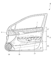
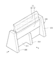
- FIG. 1 is an explanatory view of a door lining 1 as a door interior member and a vehicle body panel P to which the door lining 1 is attached as viewed from the passenger compartment side
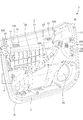
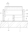
- FIG. 2 is FIG.
- the door lining 1 shown in the above is an explanatory view seen from the back side
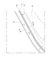
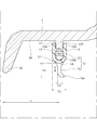
- FIG. 3 is a partially enlarged view showing the part A of FIG. 2 in an enlarged manner.
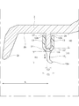
- 4 and 5 are cross-sectional views of the door lining 1 along the IV-IV line of FIG. 3
- FIG. 4 is a view showing a state before the door lining 1 is attached to the vehicle body panel P
- FIG. 6 is a cross-sectional view showing another example (protruding portion 120) of the protruding portion formed on the back surface of the door lining 1.
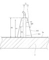
- 7A to 7C are views showing another example (protruding portion 220) of the protruding portion formed on the back surface of the door lining 1,
- FIG. 7A is a perspective view
- FIG. 7B is a front view seen from the arrow G of FIG. 7A.
- FIG. 7C is a side view seen from the arrow J of FIG. 7A.
- the door lining 1 as a door interior member will be described as an example.
- the door lining 1 is a member provided on the vehicle interior side of a vehicle door D that is openable and closable to the vehicle for the purpose of interior decoration, for example, and is formed of synthetic resin to provide not only interior decoration but also sound insulation. It has a function as a member for sound absorption and protection of occupants in the event of a collision.
- the door lining 1 of the present embodiment includes an upper portion 21, a center portion 22, and a lower portion 23, and the upper portion 21, the center portion 22, and the lower portion 23 are provided. They are connected to form the main body 2 of the door lining 1.
- the upper portion 21 is equipped with a knob for opening and closing the door (not shown), and the door pocket portion 24 is provided below the lower portion 23.
- the center portion 22 is provided with an armrest 27.
- the door lining 1 includes a power window switch (not shown) for raising and lowering the window glass, a speaker (the speaker grill 25 is displayed in FIG. 1), and a door lock knob for locking and unlocking the door lock device (not shown).
- a power window switch for raising and lowering the window glass
- a speaker the speaker grill 25 is displayed in FIG. 1
- a door lock knob for locking and unlocking the door lock device (not shown).
- An inside handle (not shown) for opening the door, etc. are installed (not shown).
- the main body 2 in which the upper portion 21, the center portion 22, the lower portion 23, and the like are combined is assembled to the vehicle body panel P.
- a linear member is attached to the outer peripheral end thereof. The linear member is visible from the outside even after being assembled to the vehicle panel, but the position of the linear member is easily displaced from the outer peripheral end, and when the door lining is assembled to the vehicle panel, the position of the linear member is The work had to be done while paying attention to the deviation, and the installation workability was lowered.
- the door lining 1 of the present embodiment includes a main body 2 having an upper portion 21, a center portion 22, and a lower portion 23. Then, as shown in FIGS. 2, 4 to 7C, the protruding portions 20 and 220 as mounting portions for attaching the cushioning member 11 are on the back surface 2a of the main body 2, in other words, on the back surface of the door lining 1 facing the vehicle body panel P. It will be provided.
- the cushioning member 11 is a member attached to the protrusions 20 and 220.
- the cushioning member 11 has an engaging portion 12 that engages with the protruding portions 20 and 220 and an abutting portion 15 that extends from the engaging portion 12 and elastically abuts on the vehicle body panel P so as to be attached to the protruding portions 20 and 220.
- the contact portion 15 is a vehicle body panel P located on the opposite side of the main body 2 from the end portion (joint portion 16) opposite to the end portion (tip 12a) of the engaging portion 12 into which the protruding portions 20 and 220 are inserted. Extends toward (in the direction of arrow E in FIG. 4). In other words, the contact portion 15 is formed so as to extend in the direction perpendicular to the back surface 2a of the main body 2 and come into contact with the vehicle body panel P (see FIG. 5).
- the contact portion 15 elastically contacts the vehicle body panel P before the door lining 1 is assembled to the vehicle body panel P, it is possible to prevent the main body 2 of the door lining 1 from directly colliding with the vehicle body panel P. As a result, the abnormal noise generated during assembly is suppressed. Further, since the cushioning member 11 is attached to the protrusions 20 and 220 by the engaging portion 12, the operator can attach the main body 2 to the vehicle body panel P without worrying about the displacement of the cushioning member 11. , Installation workability is improved.
- the protruding portion 20 is arranged along the outer peripheral edge 2c of the main body 2 as shown in FIG. Further, as shown in FIG. 4, the protruding portion 20 is arranged inward from the outer peripheral edge 2c of the main body 2 at a predetermined distance L. By being attached to the protruding portion 20, the cushioning member 11 is arranged along the outer peripheral edge 2c of the main body 2 at a predetermined distance L inward from the outer peripheral edge 2c as shown in FIGS. 2 to 4.
- the cushioning member 11 is not directly attached to the outer peripheral edge 2c of the door lining 1.
- the cushioning member 11 By attaching the cushioning member 11 at a position L away from the outer peripheral edge 2c by a predetermined distance L, after assembling the door lining 1 to the vehicle body panel P, the cushioning member 11 is hidden inside the main body 2 and is directly visible from the outside. Can't be done.
- the design of the door lining 1 is improved, and the operator can perform the mounting work without worrying about the displacement of the cushioning member 11.
- FIG. 2 by arranging the cushioning member 11 linearly along the outer peripheral edge 2c of the main body 2, it is possible to suppress the formation of a gap between the door lining 1 and the vehicle body panel P.
- the cushioning members 11 may be continuously arranged in a linear shape, or a plurality of cushioning members 11 may be arranged intermittently at intervals.
- the main body 2, the protruding portion 20, and the engaging portion 12 of the cushioning member 11 of the door lining 1 are made of polypropylene.
- the contact portion 15 is formed by a thermoplastic elastomer.
- the engaging portion 12 and the contact portion 15 are manufactured by two-color molding.
- the engaging portion 12 may be formed by a thermoplastic elastomer.
- the contact portion 15 is preferably formed of a material softer than the engaging portion 12.
- the width C2 of the contact portion 15 is formed shorter than the width C1 of the engaging portion 12.
- the abutting portion 15 is likely to bend when the abutting portion 15 abuts on the vehicle body panel P.
- the engaging portion 12 of the cushioning member 11 has a U-shaped cross section, and is a groove-shaped press-fitting portion extending along the longitudinal direction of the cushioning member 11 (direction of arrow F in FIG. 3). 14 is formed.
- the press-fitting portion 14 is formed with an opening 17 into which the protruding portion 20 is inserted, and a pair of locking claws 13 are arranged to face the inner wall surface of the press-fitting portion 14 at the end portion on the opening 17 side. ..
- the pair of locking claws 13 are formed so that the distance W2 (width of the opening 17) increases toward the tip 12a (the end on the main body 2 side) of the engaging portion 12.
- each of the pair of locking claws 13 is formed so that the width of the locking claw 13 decreases toward the tip 12a of the engaging portion 12. Therefore, it becomes easy to insert the protruding portion 20 into the press-fitting portion 14 of the engaging portion 12, and the mountability when the cushioning member 11 is attached to the protruding portion 20 is improved.
- the protruding portion 20 is press-fitted into the press-fitting portion 14 of the cushioning member 11 and is sandwiched by the pair of locking claws 13, so that the protruding portion 20 is hard to come off from the press-fitting portion.
- a pair of locking claws 13 are formed inside the press-fitting portion 14 so as to sandwich the protruding portion 20 (opening 17), but the locking claws 13 may be formed on one of the wall surfaces.
- the tip 15a of the contact portion 15 of the cushioning member 11 is in the direction perpendicular to the back surface 2a of the main body 2 (direction of arrow E in FIG. 4), that is, the contact portion 15 is the engaging portion 12. It is formed so as to be inclined with respect to the direction extending from. Therefore, when the door lining 1 is attached to the vehicle body panel P, the contact portion 15 abuts on the vehicle body panel P and falls in an inclined direction as shown in FIG. That is, they always fall to the same side. As a result, it is possible to prevent a gap from being formed between the contact portion 15 and the vehicle body panel P. Further, since the tilting direction of the contact portion 15 is determined in a specific direction, it is not necessary to temporarily remove and reattach the contact portion 15 in order to correct the tilted direction after mounting, which improves workability.
- the tip 15a of the contact portion 15 is tilted so that the contact portion 15 is tilted inward of the door lining 1, but the contact portion 15 is tilted to the outside of the door lining 1.
- the tip 15a of the contact portion 15 may be inclined. That is, the tip 15a of the contact portion 15 may be inclined to the inside or the outside of the door lining 1 as long as the direction of inclination is determined in one direction throughout the cushioning member 11.
- the contact portion 15 is formed so that the width of the contact portion 15 becomes narrower from the joint portion 16 with the engaging portion 12 toward the tip 15a.
- the contact portion 15 and the engaging portion 12 are stably joined. Therefore, the contact portion 15 is prevented from being disengaged from the engaging portion 12.
- the length from which the contact portion 15 of the cushioning member 11 extends is the length H1 when the contact portion 15 does not contact the vehicle body panel P. It is preferable that the length H2 when the contact portion 15 comes into contact with the vehicle body panel P is shorter than that (see FIGS. 4 and 5).
- FIG. 6 shows a protrusion 120, which is another example of the protrusion 20.
- the width W1 of the press-fitting portion 14 is formed wider than the distance W2 of the pair of locking claws 13 arranged so as to face each other. Therefore, when the protruding portion 120 is press-fitted into the press-fitting portion 14 of the cushioning member 11, the width of a part of the protruding portion 120 sandwiched by the pair of locking claws 13 is narrowed, while the tip 120a of the protruding portion 120 It deforms to widen the width. Therefore, the tip 120a of the protrusion 120 is caught by the pair of locking claws 13, and the cushioning member 11 is more difficult to come off from the protrusion 120.
- the protruding portion 20 shown in FIGS. 3 to 5 was formed along the outer peripheral edge 2c of the main body 2 of the door lining 1, but the position of the protruding portion 20 is not limited to this, as long as it is inside the main body 2. It may be provided at an arbitrary position.
- a protrusion 220 is provided at an arbitrary position on the back surface 2a of the main body 2 (the back surface of the upper portion 21, the back surface of the center portion 22, and the back surface of the lower portion 23), and the cushioning member 11 is attached. You may.
- the protrusion 220 which is another example of the protrusion 20, is shown in FIGS. 7A to 7C.
- the protruding portion 220 is a mounting portion for attaching the cushioning member 11.
- the protrusion 220 is a support that supports the held portion 221 that the engaging portion 12 of the cushioning member 11 engages with and extends from the back surface 2a toward the vehicle body panel P side, and the held portion 221 at both ends of the held portion 221. It has a portion 222 and a reinforcing portion 223 that supports the held portion 221 between the support portions 222.
- the cushioning member 11 is attached by inserting the tip of the held portion 221 into the press-fitting portion 14 and holding it by the engaging portion 12. When the main body 2 is assembled to the vehicle body panel P, the contact portion 15 of the cushioning member 11 abuts on the back surface of the vehicle body panel P.
- the height H4 of the protrusion 220 (held portion 221) is set along the outer peripheral edge 2c. It is necessary to change the height H4 from the back surface 2a to be higher than the height H3 of the protruding portion 20 formed.
- the held portion 221 is tilted by providing trapezoidal support portions 222 orthogonal to the held portion 221 at both ends of the held portion 221 and providing the reinforcing portion 223 between the held portions 221. Is suppressed.
- the height H6 of the reinforcing portion 223 is formed to be lower than the height H5 of the supporting portion 222 so that the cushioning member 11 can be attached to the held portion 221.
- the method of manufacturing the door lining 1 includes a step of preparing a main body 2 which is installed on the indoor side of the vehicle body panel P and has a mounting portion on a surface facing the vehicle body panel P, an engaging portion 12 which engages with the mounting portion, and the like.
- the mounting portion may be a protruding portion 20 protruding from the surface of the main body 2 facing the vehicle body panel P, and the engaging portion 12 of the cushioning member 11 is engaged with the protruding portion 20. It should be formed to fit.
- the contact portion 15 of the cushioning member 11 may be arranged along the outer peripheral edge 2c of the main body at a predetermined distance inward from the outer peripheral edge 2c. Further, in the step of preparing the cushioning member 11, the contact portion 15 may be formed of a material softer than the engaging portion 12.
- the width of the contact portion 15 may be formed shorter than the width of the engaging portion 12. Further, in the step of preparing the cushioning member 11, the engaging portion 12 may have a locking claw 13 for locking to the protruding portion 20.
- the protrusion 20 as the attachment portion may be attached by press-fitting into the engagement portion 12.
- a groove-shaped press-fitting portion 14 into which the protruding portion 20 is press-fitted is formed in the engaging portion 12 of the cushioning member 11, and a pair of locking claws 13 are press-fitted.
- the press-fitting portion 14 may be formed so as to be arranged so as to face each other inside the portion 14, and the width thereof may be wider than the interval in which the pair of locking claws 13 are arranged facing each other.
- the length of the contact portion 15 extending from the engaging portion 12 is longer than that when the contact portion 15 does not contact the vehicle body panel P. It may be formed so that it is shorter when it comes into contact with.
- the tip of the contact portion 15 may be formed so as to be inclined with respect to the direction in which the contact portion 15 extends from the engaging portion 12.
- the mounting portion a protruding portion 20 protruding from the back surface 2a of the main body 2 is provided, but this is an example, and the mounting portion may be a concave portion formed on the back surface 2a of the main body 2. In that case, the engaging portion of the cushioning member is formed so as to be insertable into the recess.
Landscapes
- Engineering & Computer Science (AREA)
- Mechanical Engineering (AREA)
- Vehicle Interior And Exterior Ornaments, Soundproofing, And Insulation (AREA)
Priority Applications (1)
| Application Number | Priority Date | Filing Date | Title |
|---|---|---|---|
| JP2022508269A JPWO2021187291A1 (enExample) | 2020-03-16 | 2021-03-11 |
Applications Claiming Priority (2)
| Application Number | Priority Date | Filing Date | Title |
|---|---|---|---|
| JP2020-045730 | 2020-03-16 | ||
| JP2020045730 | 2020-03-16 |
Publications (1)
| Publication Number | Publication Date |
|---|---|
| WO2021187291A1 true WO2021187291A1 (ja) | 2021-09-23 |
Family
ID=77771355
Family Applications (1)
| Application Number | Title | Priority Date | Filing Date |
|---|---|---|---|
| PCT/JP2021/009709 Ceased WO2021187291A1 (ja) | 2020-03-16 | 2021-03-11 | ドア内装部材 |
Country Status (2)
| Country | Link |
|---|---|
| JP (1) | JPWO2021187291A1 (enExample) |
| WO (1) | WO2021187291A1 (enExample) |
Citations (5)
| Publication number | Priority date | Publication date | Assignee | Title |
|---|---|---|---|---|
| JP2012087849A (ja) * | 2010-10-18 | 2012-05-10 | Toray Ind Inc | 衝撃吸収構造体 |
| DE102012109044A1 (de) * | 2012-09-25 | 2014-03-27 | Dr. Ing. H.C. F. Porsche Aktiengesellschaft | Fahrzeugtür mit Türverkleidung |
| JP2014205445A (ja) * | 2013-04-15 | 2014-10-30 | 河西工業株式会社 | 車両用内装部品 |
| JP2016175600A (ja) * | 2015-03-20 | 2016-10-06 | 豊田鉄工株式会社 | 車両用内装部品 |
| JP2017019489A (ja) * | 2015-07-10 | 2017-01-26 | 大和化成工業株式会社 | 車両用緩衝部品 |
Family Cites Families (4)
| Publication number | Priority date | Publication date | Assignee | Title |
|---|---|---|---|---|
| JPH0320704U (enExample) * | 1989-07-10 | 1991-02-28 | ||
| JP2002147419A (ja) * | 2000-11-09 | 2002-05-22 | Kasai Kogyo Co Ltd | 取付部構造 |
| JP2008309235A (ja) * | 2007-06-14 | 2008-12-25 | Takeda:Kk | 盗難防止用ボルトキャップ |
| JP5059817B2 (ja) * | 2009-08-21 | 2012-10-31 | 豊田鉄工株式会社 | トリムボードのクリップ組付構造、クリップ、およびクリップ組付方法 |
-
2021
- 2021-03-11 WO PCT/JP2021/009709 patent/WO2021187291A1/ja not_active Ceased
- 2021-03-11 JP JP2022508269A patent/JPWO2021187291A1/ja active Pending
Patent Citations (5)
| Publication number | Priority date | Publication date | Assignee | Title |
|---|---|---|---|---|
| JP2012087849A (ja) * | 2010-10-18 | 2012-05-10 | Toray Ind Inc | 衝撃吸収構造体 |
| DE102012109044A1 (de) * | 2012-09-25 | 2014-03-27 | Dr. Ing. H.C. F. Porsche Aktiengesellschaft | Fahrzeugtür mit Türverkleidung |
| JP2014205445A (ja) * | 2013-04-15 | 2014-10-30 | 河西工業株式会社 | 車両用内装部品 |
| JP2016175600A (ja) * | 2015-03-20 | 2016-10-06 | 豊田鉄工株式会社 | 車両用内装部品 |
| JP2017019489A (ja) * | 2015-07-10 | 2017-01-26 | 大和化成工業株式会社 | 車両用緩衝部品 |
Also Published As
| Publication number | Publication date |
|---|---|
| JPWO2021187291A1 (enExample) | 2021-09-23 |
Similar Documents
| Publication | Publication Date | Title |
|---|---|---|
| CN107444080B (zh) | 车身构造 | |
| JP5994646B2 (ja) | 車両の内装部材の取付け構造 | |
| CN110065534A (zh) | 车辆侧部构造 | |
| JP4788967B2 (ja) | 車両用ドアトリム | |
| WO2021187291A1 (ja) | ドア内装部材 | |
| JP7160599B2 (ja) | 見切りシール取付構造 | |
| JP2019214330A (ja) | 自動車用ドアウエザーストリップ | |
| JP5327623B2 (ja) | 車両用ドア構造 | |
| JP4553851B2 (ja) | ドアグリップの取付構造 | |
| KR200464066Y1 (ko) | 자동차용 암레스트 조립구조 | |
| JP6597152B2 (ja) | 車両のドア開口部構造 | |
| JP7402677B2 (ja) | 車両構造 | |
| JP2007314067A (ja) | ピラーガーニッシュの上部合わせ構造 | |
| JP2009154772A (ja) | ガラスラン | |
| JP3812786B2 (ja) | 自動車のダッシュサイドトリムの取付構造 | |
| JP5513770B2 (ja) | ウェザーストリップの取付構造 | |
| JP7710381B2 (ja) | 車両用サイドドア | |
| JP5041818B2 (ja) | 自動車用バイザー取付ブラケット | |
| JP5343717B2 (ja) | 車両用内装部材の取付構造 | |
| JP2011068311A (ja) | 車両の側部車体構造 | |
| JP2020083206A (ja) | サイドバイザー | |
| KR100320820B1 (ko) | 자동차의 테일게이트용 트림부재의 장착구조 | |
| JP2010076737A (ja) | 内装部品の合わせ部構造 | |
| KR200377569Y1 (ko) | 자동차 도어 | |
| JP2000168459A (ja) | リヤピラートリムの接合構造 |
Legal Events
| Date | Code | Title | Description |
|---|---|---|---|
| 121 | Ep: the epo has been informed by wipo that ep was designated in this application |
Ref document number: 21772605 Country of ref document: EP Kind code of ref document: A1 |
|
| ENP | Entry into the national phase |
Ref document number: 2022508269 Country of ref document: JP Kind code of ref document: A |
|
| NENP | Non-entry into the national phase |
Ref country code: DE |
|
| 122 | Ep: pct application non-entry in european phase |
Ref document number: 21772605 Country of ref document: EP Kind code of ref document: A1 |